

Page 1
H OM E & BU SI NE SS S EC UR IT Y
W W W . L O R E X C C T V . C O M
L15LD400 Series
Quick Start Guide
INFORMATION IN THIS DOCUMENT IS SUBJECT TO CHANGE WITHOUT NOTICE. AS OUR PRODUCTS A RE SUB JEC T TO CONTINUOUS
IMPROVEMENT, LORE X TECHNOLOGY AND OUR SUBSIDI ARIES RESERVE T HE RIGHT TO MODIF Y PRODUC T DESIGN, SPECIF ICATIONS
AND PRICES, W IT HOU T NOTICE AND WITHOUT INCURRING A NY OBLIGATION. E&OE © 2 007 LORE X. ALL RIGH TS RESERV ED.
Page 2
2
under 30 minutesunder 15 minutes under 60 minutes
Hand Tools Hardware
Router
Hi Speed
over 60 minutes
Skill Level
Time
under 30 minutesunder 15 minutes under 60 minutes
Hand Tools Hardware
Router
Hi Speed
over 60 minutes
Router
Hi Speed
over 60 minutes
Hi Speed
over 60 minutes
Hi Speed
over 60 minutes
Hi Speed
over 60 minutes
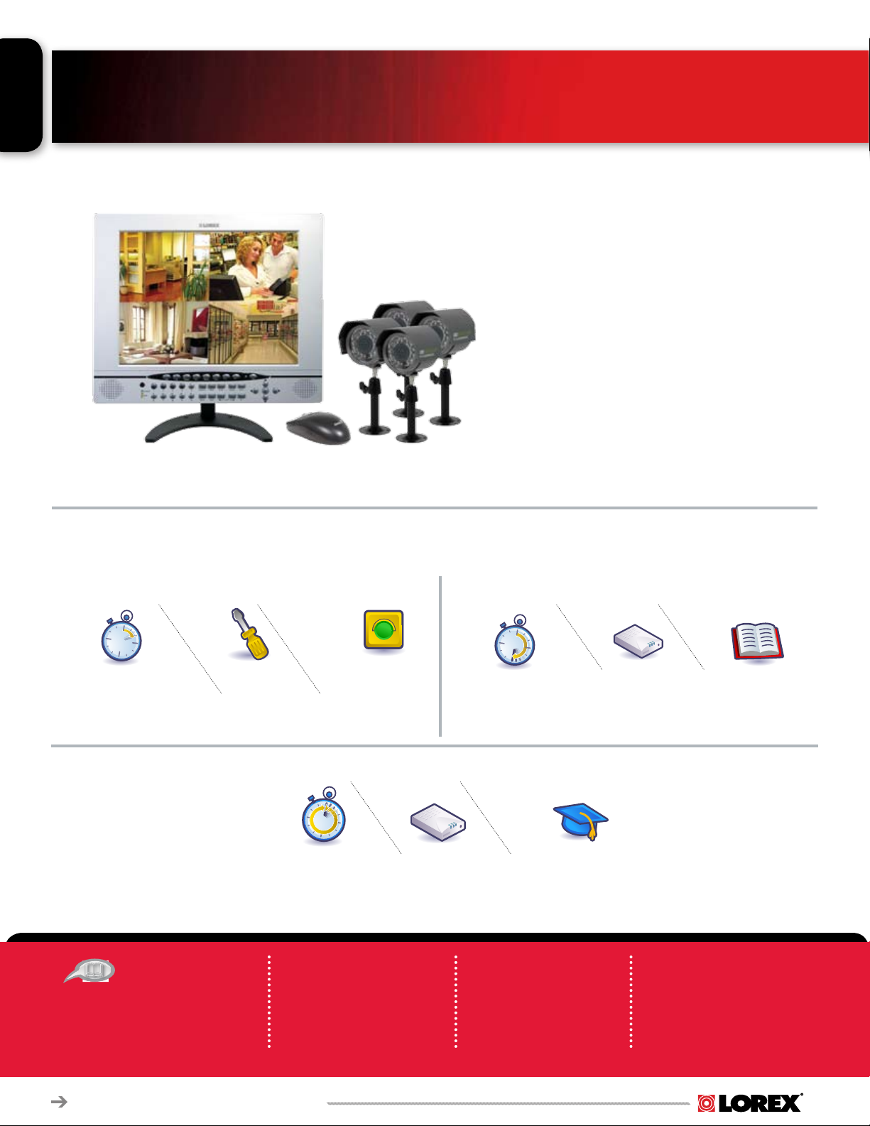
PACKAGE CONTENTS AND
INSTALLATION GUIDE:
System Contents:
1 - 15” 4 Channel LCD Monitor with 160GB HDD
1 - 10 ft Ethernet Cable
1 - Remote Control
2 - AAA Batteries
1 - Power Adaptor (for monitor)
1 - 4 in 1 Power Adaptor (for cameras)
1 - Lorex Client 2.0 Software CD
1 - PS2 Mouse
4 - Color CCD IR Weather Resistant Cameras
4 - 60 ft Extension Cables
4 - Metal Camera Stands with Mounting Screws
1 - User’s Manual
1 - Software Manual
1 - Quick Start Guide
INSTALLATION GUIDE
STEP 1 STEP 2
Time Tools Skills - Easy
Under 10 Minutes*
* Installation time may vary based on
application and camera cabling
RECOMMENDED
Check Pages 9 and 10 for
TIPS:
recommended tips .
Hand Tools
Plug & Play connectors,
On screen set up
STEP 3
Time Hardware
60 Minutes
* Installation time may vary
based on application
ATTENTION:
Broadband Router and
Computers are required
(for local and remote
monitoring), not included.
Time Skills - Intermediate
Computer &
Router*
INSTRUCTIONS:
For detailed setup
Under 30 Minutes*
* Installation time may
vary based on application
Skills - Advanced
Basic Computer
Skills, Router Port
Forwarding
information, please
refer to your User ’s
manual.
Hardware
Computer &
Router*
* Minimum System Requirement: Windows XP,
Pentium IV, 256MB Ram (512MB Recommended),
200MB Storage, Internet, DSL or Cable Modem
* Minimum System Requirement: Windows XP,
Pentium IV, 256MB Ram (512MB Recommended),
200MB Storage, Internet, DSL or Cable Modem
Plug & Play connectors,
On screen set up
SOFTWARE
REQUIREMENTS:
For Lorex Client 2.0
Sof tware requirement s,
please refer to Page 9 of
this guide.
L15LD400 Series Quick Set-Up Guide R1
Page 3
1
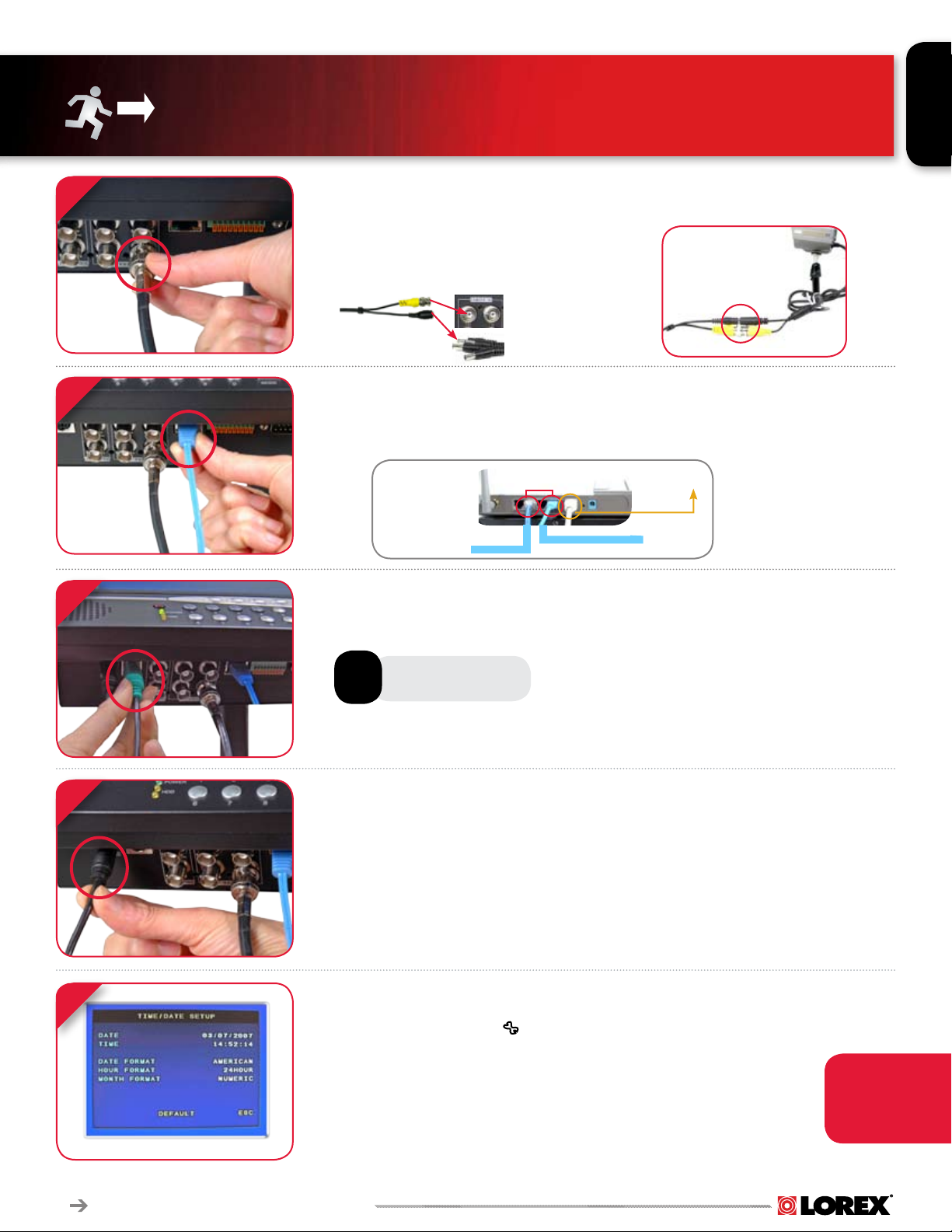
STEP 1 - SET UP YOUR MONITOR FIRST
CONNECT CAMERAS TO THE MONITOR:
Connect the first camera to the CH1 input. Follow the same steps to connect the
additional cameras.
1. Connect the Female BNC end of the supplied 60’ extension cable to the camera.
Connect the male Power end of the the extension cable to the camera.
2. Connect the Female end of the supplied 60’ extension cable to an open BNC
camera input on the back of the System. Connect the female Power end of the
the extension cable to one of end of the 4 in one power adaptor.
IMPORTANT NO TE: The ends of the extensi on cable are N OT
the same - o ne end has a Male power por t, and the oth er has
a Female pow er port. Befo re permanently running the C amera
Extension Ca ble, make sur e that the cab le has been or iented
between the Camera and th e unit correct ly
3
2
3
4
CONNECT ETHERNET CABLE:
Connect one end of the ethernet cable to one of the router’s (not included) LAN
PORTS and the other end to Monitor’s Network Port located at the bottom of the
monitor. See picture below showing a generic LAN/WAN connection.
LAN (LOCAL AREA NETWORK)
BACK OF THE ROUTER SHOWN
TO YOUR COMPUTER
WAN (WIDE
AREA NETWORK)
TO YOUR MONITOR
CONNECT THE MOUSE:
Connect the 6 PIN end of the Mouse included with your system to the PS2 port of
the monitor.
MOUSE CONTROL
AVAILABLE
CONNECT POWER CABLE:
Connect one end of the Power adaptor to the monitor, the other end to an electrical
outlet. This unit powers ON once it is plugged in to the power outlet.
5
L15LD400 Series Quick Set-up Guide R1
** After you see all four (4) camera images on your monitor screen, remove the
protective film from camera(s) and monitor screen.
SET THE TIME AND DATE:
1. Press the MENU button from the Front Panel of the Monitor (or Remote Control), or use the
Mouse and Click the Menu Icon located at the bottom of the monitor screen (Show and
hide screen becomes available when the Mouse pointer is placed at the bottom of the Monitor).
2. DVR LOG IN screen appears soon after the Menu button is pressed asking for a password.
Note: USER ID BY DEFAULT IS ADMIN. Password is numeric and not necessarily needed for
initial MENU setup. Press ENTER to enter the MAIN MENU.
3. On the MENU screen select CONFIGURATION and click ENTER.
4. Select TIME AND DATE SETUP to change or alter the factory default settings and press ESC to
exit this menu.
Congratulations! You have completed Step 1 successfully. You can now view, record
and playback images on your monitor.
Make sure that
the Date and Time
are set prior to
recording.
Page 4
4
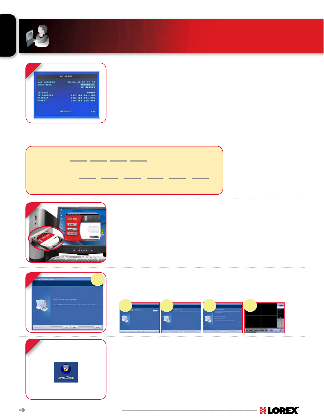
STEP 2 - SET UP LOCAL VIEWING ON YOUR PC
1
*YOUR OBSERVATION SYSTEM MUST
BE CONNECTED TO A ROUTER PRIOR TO
POWERING IT ON.
IP ADDRESS: . . .
MAC ADDRESS:
(Required for DDNS registration)
2
RETRIEVE SYSTEM INFORMATION:
1. Access the Main Menu Setup screens, and navigate to the SYSTEM
MENU - EXTERNAL DEVICE - TCP/IP SETUP - IP SETUP option.
2. Record the MAC Address of your system. This information is NECESSARY
for the DDNS Setup process.
3. Confirm that the DHCP MODE is set to AUTOMATIC. This will allow your
system to lease an IP ADDRESS from your router. If the system not set to
AUTOMATIC, change the setting and click IP DETECT - the system will
obtain an IP address.
4. The IP PORT is 50000 by default. The IP Address, Gateway and Subnet are
assigned to your system by your router. If the settings are not displayed,
and the unit is set to DHCP MODE: AUTOMATIC, you may need to click IP
DETECT - the system will obtain an IP address.
RECORD THE IP AND MAC ADDRESSES IN THE SECTION BELOW:
NOTE: The system will lease networking
information from your Router. If you wish
to set your information manually, then
set the DHCP MODE to MANUAL. Please
consult your Hardware Manual for further
Menu options.
INSTALL SOFTWARE:
(on your local computer)
Insert the Lorex Client 2.0 Software CD into your local computer’s
CD ROM drive and proceed with the installation.
3
4
1
For Lorex Client Software
requirements, please refer to
Page 9 of this guide.
LOREX CLIENT 2.0 SOFTWARE:
(on your local computer)
Follow the installation screens to complete Lorex Client 2.0
Software installation.
2 3 4 5
LOREX CLIENT 2.0 SOFTWARE:
(on your local computer)
Close the CD Menu Screen. A Lorex Client Icon will appear on your
desktop.
RUN THE LOREX CLIENT 2.0 SOFTWARE:
(on your local computer)
Double-click the Lorex Client 2.0 Software icon on your desktop to run the
program.
L15LD400 Series Quick Set-Up Guide R1
Page 5

STEP 2 - SET UP LOCAL VIEWING ON YOUR PC
CONTINUED
5
5
6
SET-UP:
(on your local computer for local viewing)
Click the SETUP button from the Lorex Client 2.0 Software Screen.
LOREX CLIENT 2.0 REMOTE ACCESS SETUP
(on your local computer for local viewing):
1. Select the IP/PORT Tab.
MANUAL (for local viewing).
2. Click
3. NAME: Enter a name for the system. E.g. Office
4. ADDRESS: Add the IP address recorded earlier at Step 2 - 1
5. PORT: By default is set to 50000
6. USER ID: By default is admin
7. PASSWORD: Leave it blank
8. Press SAVE to add the system name you have created.
7
VIEW CAMERAS LOCALLY:
(on your local computer for local viewing):
From the Lorex Client 2.0 software - local configuration screen (as shown in the picture), press the Connect button to connect to Local Live site to view your cameras.
Congratulations! You have completed Step 2 successfully.
You can now view and playback images on your local
computer over the Local Area Network (LAN).
L15LD400 Series Quick Set-up Guide R1
Page 6
6
STEP 3 - SET UP INTERNET REMOTE SECURITY
MONITORING
1
2
3
PORT FORWARD YOUR ROUTER:
Port forward your router first before proceeding with the set-up (port
50000).
All routers are different. To port forward your router, please refer to
your router’s user manual.
A router configuration gude is available on your Lorex Client Software
CD and also on www.lorexcctv.com/support in the Consumer’s Guide
Section.
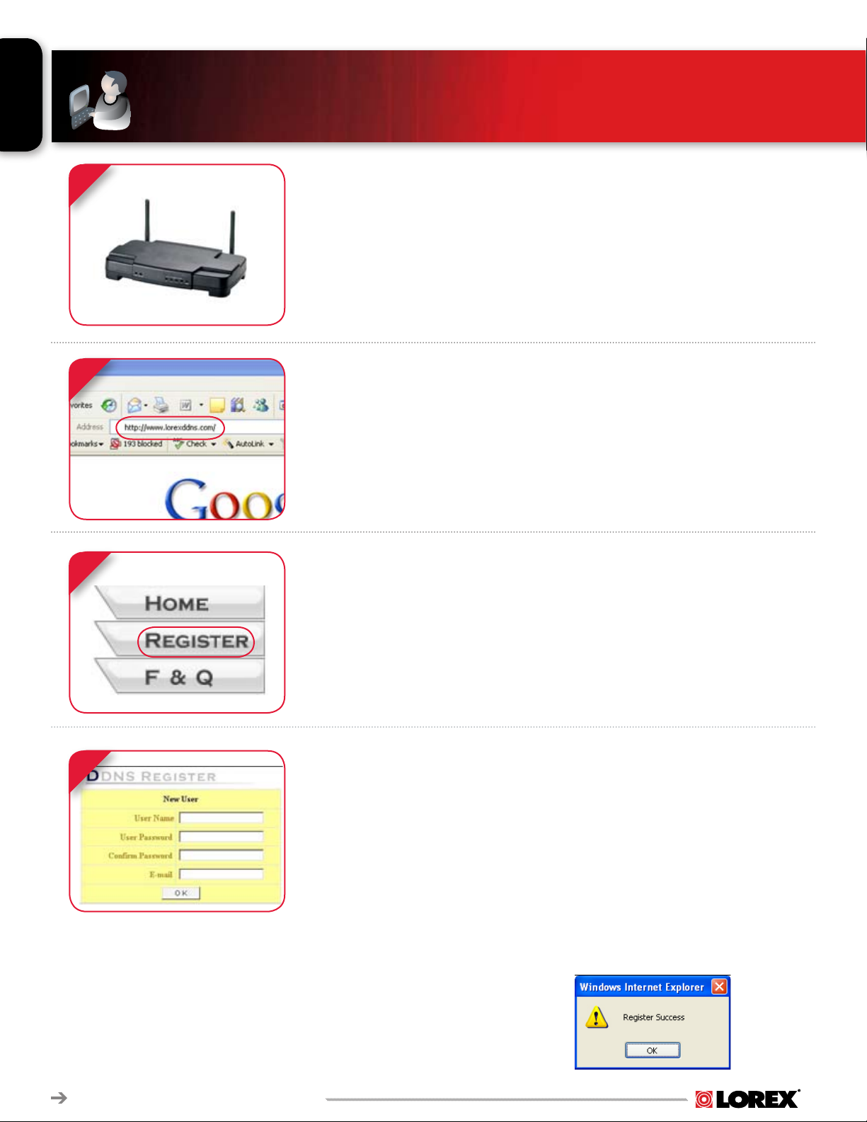
DDNS SET-UP:
Open your web browser (Internet Explorer by default) and enter
http://www.lorexddns.com in the address bar.
DDNS REGISTRATION:
4
Select the REGISTER option from the list on the left side of the
screen.
CREATE NEW USER INFORMATION:
Complete the NEW USER fields with your personal information:
• USER NAME - Enter the desired User Name for connection.
• USER PASSWORD / CONFIRM PASSWORD - Enter and confirm a
password for the connection.
NOTE: The username and password provided are NOT the same as the ADMIN/
PASSWORD on the Observation System. These credentials are used for your
specific connection to your unit.
• EMAIL - Enter your Email Address.
Press the OK button to save the settings.
L15LD400 Series Quick Set-Up Guide R1
A Successful Registration window will appear.
Page 7

STEP 3 - SET UP INTERNET REMOTE SECURITY
5
6
MONITORING
LOGIN:
Once the account has been created, you will need to login using your
credentials (as set in step 4).
Once the Username and Password have been entered, press the LOG IN button to
access the Configuration Menu.
ADD DVR:
Select the ADD DVR link from the top of the page.
The DVR Setup screen will appear:
• DVR NAME - Enter the desired name for your Observation System (e.g.
MyBusiness) to a maximum of 20 numbers and letters.
• MAC ADDRESS - Enter the MAC Address from the system (as retrieved
from the System Information in the IP & MAC Address section on page 4). The
MAC ADDRESS IS 12 CHARACTERS WITH NO SPACES OR DASHES.
• IP ADDRESS & PORT - This information can be left blank - the DDNS Service
will access your unit based on the MAC Address.
7
7
Press OK to save the settings. Once the settings are saved, the configuration will
appear in your DDNS List. This configuration can now be added to the Observation
System.
ENTER DDNS SET-UP ON YOUR MONITOR:
Access the Main Menu Setup screens, and navigate to the SYSTEM MENU
- EXTERNAL DEVICE - TCP/IP SETUP - DDNS SETUP option.
L15LD400 Series Quick Set-up Guide R1
Page 8

STEP 3 - SET UP INTERNET REMOTE SECURITY
8
8
9
MONITORING
ENABLE DDNS SETTINGS:
• Set the DDNS ENABLE to ON
• Click on REGISTER
The following will automatically complete after clicking the Register option:
• DNS SERVER - Confirm that the IP address is set to 202.133.244.128
• INTERVAL - Set an interval for the DVR to auto-update its IP address to DDNS server (D-
days / H- hours / M- minutes).
• REGISTER - Connect to the DDNS server and register the DVR information to DDNS database
• DNS STATUS - Indicates the current status of DDNS connection.
• IP ADDRESS - Indicates the local IP address assigned by the router (the internal IP address of
your system).
• IP PORT - Indicates the current port number in the system (50000 by default).
• REMAIN TIME - Indicate the remaining time until the System next updates the IP address with
the DDNS Service.
• LAST REGISTRATION DATE - Indicates the last successful date and time that an update
occurred. Save the changes, and exit from the menu.
LOREX CLIENT 2.0 REMOTE ACCESS SETUP:
The remote connection information needs to be added to the Lorex Client software to allow
for a remote connection (using DDNS).
CONTINUED
10
1. Load the Lorex Client 2.0 Software. Click on SETUP to add the configuration.
2. The Remote Viewer Setup window will load to the
(all settings will be greyed out).
MyBusiness
3. Enter your
• USER NAME - Enter the user name you configured on the DDNS Website (default is set to
GROUP as an example, and can be deleted).
• DVR NAME - Enter the DVR name you configured on the DDNS Website.
4. Click the
5. Click on the
Server.
6. Enter the
• USER ID - admin (default)
• PASSWORD - leave blank (default)
NOTE: It is highly recommended that you change the System password. Please refer to
your Hardware Manual for menu settings.
7. Press
DDNS Information as follows:
SAVE Button to accept the settings.
GET IP button to retrieve the IP Address and Port Number from the DDNS
USER ID AND PASSWORD for the Observation System:
OK to save the settings, and close the configuration window.
IP/PORT Tab. Click on the DDNS option
VIEW CAMERAS REMOTELY:
Click the CONNECT button to remotely access your Observation System.
Remote Viewing with Internet Explorer: Video from the Observation System can be viewed using the
Internet Explorer interface (for remote viewing and backup). All Remote functionality through the Internet
Explorer interface is provided at http://www.lorexddns.com. For more information, please refer to Lorex
Client 2.0 Software Manual.
L15LD400 Series Quick Set-Up Guide R1
Congratulations! You have completed Step 3 successfully. You can
now view and playback images on your remote computer over the
Internet.
Page 9

RECOMMENDED TIPS
LOCATE MONITOR CONNECTIONS:
Tilt the monitor UP to loacte your
monitor’s connections.
FUNCTION ICONS - AVAILABE FOR USE
ONLY THROUGH A MOUSE
9
2
1
3
FULL SCREEN CH 1 ~4
4
QUAD MODE
MENU
TO PAN/TILT/ZOOM
PT Z
CAMERA
TO VIEW IMAGE IN PICTURE
IN PICTURE MODE
ZOOM
LOREX CLIENT 2.0 SOFTWARE REQUIREMENTS:
The Lorex Client 2.0 software (included with the
Observation System) has the following installation
requirements:
MiniMuM SySteM RequiReMentS:
OPERATING SYSTEM: Windows 2000, Windows XP
Home Edition, Windows XP Professional
PROCESSOR: Pentium 4 - 1.5 GHz Processor (or
equivalent)
MEMORY: 256 MB RAM
HARD DRIVE: 50 MB - Installation space required.
* Additional Hard Drive space required for recording.
Recorded file size will vary depending on recording
quality settings
RecoMMended SySteM RequiReMentS:
OPERATING SYSTEM: Windows XP Home Edition,
Windows XP Professional
PROCESSOR: Pentium 4 / 3 GHz Processor (or
equivalent)
MEMORY: 1024 MB RAM
Hard Drive: 50 MB - Installation space required
* Additional Hard Drive space required for recording.
Recorded file size will vary depending on recording
quality settings
** Requires a high speed internet connection
(minimum upload speed: 256Kb/s, download speed
512Kb/s) and a broadband router – not included.
Typical network remote viewing at 1-2 FPS.
PLAY IN SEQUENCE
OPENS SEARCH WINDOW
QUICK PLAYBACK
Function icons can be located at the
bottom of the Monitor screen (as
shown above). A Show and Hide
screen readily becomes available
when the Mouse pointer is pointed to
the bottom of the Monitor.
Please refer to the Lorex Client V2 Software
User Guide included with your Observation
System for further details.
Visit the Lorex support website at http://www.
lorexcctv.com for information on Windows
Vista compatibility.
L15LD400 Series Quick Set-up Guide R1
Page 10

10
RECOMMENDED TIPS CONTINUED
HDD INSTALLATION:
The System comes with a pre-installed Hard Drive, however
the unit will work with a replacement single Hard Drive (up to
400GB).
NOTE: Make sure that the System is OFF and the power cable has been
disconnected before changing the Hard Drive. For detailed instructions,
check your user’s manual included with the system.
SETTING THE NEW DRIVE TO MASTER:
• Refer to the General Jumper Pin Setting on HDD Surface (generally
located on a sticker on the top of the drive).
• Set the Jumper Pin Set to Master (1 Drive). NOTE: Use a Hard Drive
Model with a power supply rated UDMA66 or higher.
Pre-installed
160 GB HDD
CONNECTING THE IDE CABLE:
• Confirm the IDE Cable is securely connected within the System.
FORMATTING THE NEW HARD DRIVE:
The New Hard Drive MUST be formatted. If a new HARD DRIVE is
detected, the system will prompt you to FORMAT the drive. Please
refer to the system’s user manual for HDD installation.
TIP ON CAMERA MOUNTING:
Note: Test the cameras prior to selecting a permanent mounting
location by temporarily connecting the Cameras and Cables to
your L15LD400 DVR Combo System.
TIP ON REMOTE VIEWING AND PLAYBACK:
NOTE: You must have an active internet connection to the
Observation System to be able to perform Remote viewing or
playback. Remote access is dependant on your connection
speed, internet traffic and other network factors - the speed is
normally 1~2 FPS (frames per second).
For faster playback, it is recommended to download previously
recorded video using the backup function and play it back using
Backup Player 2.0 Software - refer to the user manual for details.
L15LD400 Series Quick Set-Up Guide R1
Regardless of the network playback speed, video is being
recorded on your system in real time, and can be viewed when
you are at the system or through the backup player.
Page 11

PRODUCT SUPPORT
It’s all on the Web
www.lorexcctv.com
11
For detailed setup information, please refer to your User’s Manual. For additional
information about determining your IP address, configuring your router, and
port forwarding, please visit our website www.lorexcctv.com/support and click
Consumer Guides Section or view guides from the Lorex Client 2.0 Software CD
included with your system.
Email Support: support@lorexcorp.com
Toll Free Technical Support - North America: 1-888-42 LOREX (1-888-425-6739)
Toll Free Technical Support - International (outside of North America): 00-800-425-6739-0
Lorex International Website - www.lorexinternational.com
L15LD400 Series Quick Set-up Guide R1
PRODUCT SUPPORT
Specification Sheet
User’s Manual
Lorex Client Software Manual
Quick Start Guide
Portforwarding Guide
Basics of Remote Video
Access Guide
QUICK SET-UP GUIDE
USER’S MANUAL
FAQ
 Loading...