

Page 1
LOREX Technology Inc.
Copyright © 2006 LOREX Technology Inc. As our
products are subject to continuous improvement,
LOREX and its subsidiaries reserve the right to modify product design, specifications and prices, without
notice and without incurring any obligation. E&OE
Quick Set-up Guide
It’s all on the web
Product Information
User Manuals
Quick Start Guides
Specification Sheets
Software Upgrades
Firmware Upgrades
VISIT
www.lorexcctv.com
Technical Specifications:
* 4 Available channels for optimal signal.
** Maximum open space transmission range. Actual range dependent upon
building materials and other obstructions in path of wireless signal.
The Wireless Converter utilizes a BNC Male type of connector. Additional
accessories need to be purchased if your camera doesnot have a BNC
Female lead.
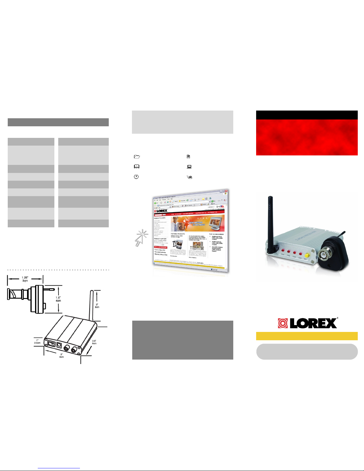
Dimensions:
4. Specifications
H O M E & B U S I N E S S S E C U R I T Y
Wired to Wireless
Camera Converter
Model WL410BNC
Frequency SM 2400 ~ 2483 MHz 4CH *
Channels
Transmission Power
Current Consumption
Modulation Mode
Bandwidth
Operating Temperature
CH1 = 2414 MHz
CH2 = 2432 MHz
CH3 = 2450 MHz
CH4 = 2468 MHz
10mW CE, 2mW FCC
50mA (MAX)
FM
18 MHz
14°F ~ 122°F
-10
°C ~ 50°C
Storage Temperature -22°F ~ 140°F
-40
°C ~ 85°C
Wireless Disclaimer
This product broadcasts over public airways and its video and audio
signals may be intercepted without your consent.
Wireless Range Up to 330 ft. (100 m) **
Page 2
1. Confirm Package Contents 2. Transmitter & Receiver Setup 3. Viewing the Camera
1 x BNC to 2.4 GHz
Wireless
Converter
1 x 4 Channel 2.4
GHz Wireless
Receiver
1 x AV Cable
1 x MiniPower Cable
1 x 12V DC Power
Adapter
Features:
• Turns any Wired CCTV camera into a 2.4 GHz
Wireless Camera
• Avoids the hassle of running cables
• Wireless video transmission through walls and ceilings
• Standard BNC Video connection to transmitter
converter
• Crystal clear 300 ft. wireless transmission (open
space)*
• 4 channels available for selecting clearest reception
• Can be connected to LOREX 6 Pin DIN cameras in
conjunction with the ACC1510 coupler
* Maximum open space transmission range. Actual range dependent upon
building materials and other obstructions in path of wireless signal
1. Set up the Transmitter:
A: Connect the Converter to a BNC Camera at the
BNC Socket.
B: Connect the mini power cable from the
Cameras’ Power Input to one of the
Converters’ Power Jacks.
C: Connect the Camera’s Power cable to the
other Power jack on the Converter, and
connect to a wall outlet.
A: Ensure the Antenna is securely connected to
the Receiver.
B: Connect the 12V power adapter to the Wireless
Receiver (make sure the receiver is OFF).
Plug the Adapter into a wall outlet.
C: Connect the Wireless Receiver to a Monitor/TV
using the supplied AV Cable:
•Connect the Yellow/Red plugs on one end of the
AV Cable to the VIDEO/AUDIO ports on the
Receiver.
•Connect the Yellow/Red plugs on the other end
of the AV Cable to the VIDEO/AUDIO ports on
the TV/Monitor.
2. Set up the Wireless Receiver:
A: Set the Receiver power to ON. By default, the
Receiver will go to CHANNEL 1 (CH1)
B: Set the Transmitter to CH1.
C: Set the Monitor / TV to Video Mode - See your
specific MONOTOR / TV Manual for further
information.
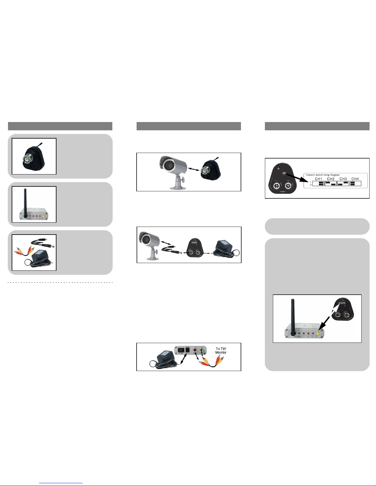
3. Viewing the Camera
IMPORTANT:
You may find some static on the picture at a
selected channel setting.
For optimum viewing reception, you may need to
change the channels on BOTH the Transmitter
and Receiver (between CH1-CH4). BOTH the
Transmitter and Receiver must be set to a
matching channel.
If Static persists on your image, try adjusting the
Antenna on the Wireless Receiver and
Transmitter, or reposition the units.
YOU SHOULD NOW SEE LIVE
VIDEO ONSCREEN!
 Loading...