

Page 1

WIRELESS HOME MONITORING SYSTEM
USER’S GUIDE
ENGLISH VERSION 1.0
LW2730/LW2930 SERIES
www.lorextechnology.com
Page 2
Thank you for purchasing the Lorex wireless video monitoring system.
This manual refers to the following models:
• LW2730 Series (7‘‘ wireless monitoring system)
• LW2930 Series (9‘‘ wireless monitoring system)
For the latest online manual, downloads, and product updates, and to learn about our
complete line of accessory products, please visit our website at:
www.lorextechnology.com
CAUTION
RISK OF ELECTRIC SHOCK
DO NOT OPEN
CAUTION: TO REDUCE THE RICK OF ELECTRIC SHOCK DO NOT
REMOVE COVER. NO USER SERVICABLE PARTS INSIDE.
REFER SERVICING TO QUALIFIED SERVICE PERSONNEL.
The lightning flash with arrowhead symbol, within an equilateral
triangle, is intended to alert the user to the presence of uninsulated
"dangerous voltage" within the products ' enclosure that may be of
sufficient magnitude to constitute a risk of electric shock.
The exclamation point within an equilateral triangle is intended to
alert the user to the presence of important operating and
maintenance (servicing) instructions in the literature accompanying
the appliance.
WARNING: TO PREVENT FIRE OR SHOCK HAZARD, DO NOT
EXPOSE THIS UNIT TO RAIN OR MOISTURE.
CAUTION: TO PREVENT ELECTRIC SHOCK, MATCH WIDE BLADE
OF THE PLUG TO THE WIDE SLOT AND FULLY INSERT.
Page 3

NEED HELP?
CONTACT US FIRST
DO NOT RETURN THIS PRODUCT TO THE STORE
Please make sure to register your product at www.lorextechnology.com
to receive product updates and technical support.
2 Easy Ways to Contact Us
Online:
Product Support is available 24/7 including product information, user
manuals, quick start up guides and FAQ’s at
www.lorextechnology.com/support
For all other matters, visit www.lorextechnology.com
By Phone:
North America:
Customer Service (for warranty matters): 1-888-425-6739 (1-888-42-LOREX)
Tech Support (for technical/installation issues): 1-877-755-6739 (1-877-75-LOREX)
Mexico: 001-800-681-9263, 001-800-514-6739
International: +800-425-6739-0
SEP 12 2012 - R14
(Example: From the UK, dial 00 instead of +)
Page 4

VIEW YOUR WORLD™
VOIR VOTRE MONDE
VEA SU MUNDO™
MD
¿NECESITA AYUDA?
COMUNÍQUESE PRIMERO
CON NOSOTROS
NO DEVUELVA ESTE PRODUCTO A LA TIENDA NE RETOURNEZ PAS CE PRODUIT AU MAGASIN
Por favor, registre su producto en www.lorextechnology.
com para recibir actualizaciones del producto y
asistencia técnica.
Hay 2 maneras fáciles de comunicarse
con nosotros:
En línea:
Apoyo al cliente está disponible 24/7, incluyendo
información del producto, manuales para el usuario, guías
de inicio rápido y preguntas más frecuentes en:
www.lorextechnology.com/support
BESOIN D’ASSISTANCE?
COMMUNIQUEZ D’ABORD
AVEC NOUS
Veuillez enregistrer votre produit sur le site
www.lorextechnology.com afin de recevoir des mises à jour
et le soutien technique pour votre produit.
2 façons simples de communiquer
avec nous :
En ligne :
À votre disposition 24/7, le soutien pour les produits comprend
les renseignements sur les produits, guides d’utilisation, guides
de départ rapide et FAQ :
www.lorextechnology.com/support
Para todo lo demás, visite
www.lorextechnology.com
Por teléfono:
Norte América:
Atención al cliente (para asuntos de la garantía):
1-888-425-6739 (1-888-42-LOREX)
Asistencia técnica (para asuntos técnicos o de instalación):
1-877-755-6739 (1-877-75-LOREX)
Mexico: 001-800-681-9263, 001-800-514-6739
Internacional: +800-425-6739-0
(Ejemplo: Desde el Reino Unido, marque el 00 en lugar del +)
Pour toutes les autres questions,
visitez www.lorextechnology.com
Par téléphone :
En Amérique du Nord :
Service à la clientèle (pour tout ce qui concerne la garantie) :
1-888-425-6739 (1-888-42-LOREX)
Soutien technique (pour les questions d’ordre technique ou relatives à
l’installation) : 1-877-755-6739 (1-877-75-LOREX)
Mexique : 001-800-681-9263, 001-800-514-6739
International : +800-425-6739-0
(par exemple : à partir du Royaume-Uni, composez le 00 au lieu de +)
SEP 12 2012 - R14
Page 5

BEFORE YOU START
Please make sure to register your product at www.lorextechnology.com
to receive product updates and technical support
THIS PRODUCT MAY REQUIRE PROFESSIONAL INSTALLATION
LOREX IS COMMITTED TO FULFILLING YOUR SECURITY NEEDS
• We have developed user friendly products and documentation.
Please read the Quick Start Guide and User Manual before you
install this product.
• Consumer Guides and Video Tutorials are available on our web
site at www.lorextechnology.com/support
• If you require further installation assistance, please visit
www.lorextechnology.com/installation or contact a
professional installer.
• Please note that once the components of this product have been
unsealed, you cannot return this product directly to the store
without the original packaging.
SEP 6 2012 - R8
Page 6

AVANT DE
ANTES DE
COMMENCER
Veuillez enregistrer votre produit sur le site
www.lorextechnology.com afin de recevoir
des mises à jour et le soutien technique pour
votre produit.
CE PRODUIT PEUT NÉCESSITER UNE
INSTALLATION PROFESSIONNELLE
LOREX S’ENGAGE À RÉPONDRE À VOS
BESOINS EN MATIÈRE DE SÉCURITÉ
• Nous avons conçu et développé une documentation
et des produits extrêmement conviviaux. Veuillez
lire le Guide de départ rapide et le Guide
d’utilisation avant d’installer ce produit.
• Des guides pour consommateurs et des tutoriels
EMPEZAR
Cerciórese de por favor colocar su producto
en www.lorextechnology.com para recibir
actualizaciones y la información del producto
y soporte técnico.
ESTE PRODUCTO PUEDE EXIGIR UNA INSTALACIÓN PROFESIONAL
LOREX SE COMPROMETE A SATISFACER
SUS NECESIDADES EN SEGURIDAD
• Favor de leer la guía de instalación rápida y la
guía del usuario antes de instalar este product.
• Puede conseguir las guías del consumidor y los
cursos en enseñanza video sobre el Internet
visitando www.lorextechnology.com/support
vidéo vous sont offerts sur notre site Web :
www.lorextechnology.com/support
• Si vous avez besoin de plus d’assistance pour
l’installation de ce produit, veuillez visiter le site
www.lorextechnology/installation ou communiquez
avec un installateur professionnel.
• Veuillez prendre note que lorsque vous avez déballé
les pièces et composantes de ce produit, vous ne
pouvez pas retourner celui-ci directement au
magasin sans son emballage original.
www.lorextechnology.com
• Si necesita ayuda para la instalación, visite
www.lorextechnology.com/installation o contacte
un especialista en instalaciones.
• Favor de notar que una vez que los componentes
de este producto han sido removidos del
embalaje, no podrá devolver este producto
directamente a la tienda.
VIEW YOUR WORLD™
VOIR VOTRE MONDE
VEA SU MUNDO™
MD
SEP 6 2012 - R8
Page 7
Important Safeguards
www.lorextechnology.com
In addition to the careful attention devoted to quality standards in the manufacture process of
your product, safety is a major factor in the design of every instrument. However, safety is your
responsibility too. This sheet lists important information that will help to ensure your enjoyment
and proper use of the product and accessory equipment. Please read them carefully before
operating and using your product.
General Precautions
1. All warnings and instructions in this manual should be followed.
2. Do not use receivers or video monitors in humid or wet places.
3. Keep enough space around the product for ventilation. Slots and openings in the storage
cabinet should not be blocked.
4. It is highly recommended to connect the product to a surge protector to protect from damage
caused by electrical surges. It is also recommended to connect the product to an
uninterruptible power supply (UPS), which has an internal battery that will keep the product
running in the event of a power outage.
5. Remove the plug from the outlet before cleaning. Do not use liquid aerosol detergents. Use a
water dampened cloth for cleaning.
Installation
1. Read and Follow Instructions - All the safety and
operating instructions should be rea d befo re the produ ct
is operated. Follow all operating instructions.
2. Retain Instructions - The safety and operating
instructions should be retained for future reference.
3. Heed Warnings - Comply with all warnings on the
product and in the operating instructions.
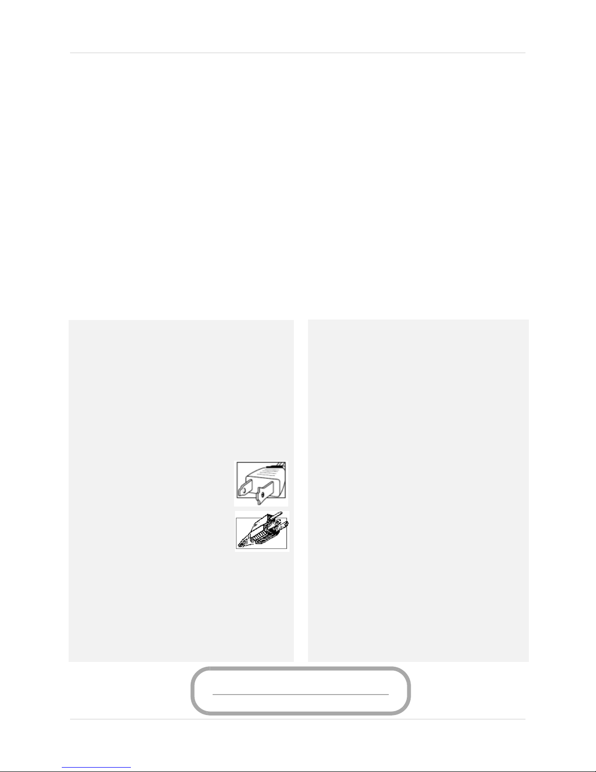
4. Polarization - Do not defeat the safety purpose of the
polarized or grounding-type plug.
A polarized plug has two blades with
one wider than the other.
A grounding type plug has two blades
and a third grounding prong.
The wide blade or the third prong are
provided for your safety.
If the provided plug does not fit into your
outlet, consult an electrician for
replacement of the obsolete outlet.
Power Sources - This product should be operated only
5.
from the type of power source indicated on the marking
label. If you are not sure of the type of power supplied
to your location, consult your video dealer or local power
company. For products intended to operate from battery
power, or other sources, refer to the operating
instructions.
6. Overloading - Do not overload wall outlets or extension
cords as this can result in the risk of fire or electric
shock. Overloaded AC outlets, extension cords, frayed
power cords, damaged or cracked wire insulation, and
broken plugs are dangerous. They may result in a
shock or fire hazard. Periodically examine the cord,
and if its appearance indicates damage or deteriorated
insulation, have it replaced by your service technician.
7. Power-Cord Protection - Power supply cords should
be routed so that they are not likely to be walked on or
pinched by items placed upon or against them. Pay
particular attention to cords at plugs, convenience
receptacles, and the point where they exit from the
product.
8. Surge Protectors - It is highly recommended that the
video equipment be connected to a surge protector.
Doing so will protect the equipment from damage
caused by power surges. Surge protectors should bear
the UL listing mark or CSA certification mark.
Uninterruptible Power Supplies (UPS) - Because
9.
this product is designed for continuous, 24/7 operation,
it is recommended that you connect the product to an
uninterruptible power supply. An uninterruptible
power supply has an internal battery that will keep the
product running in the event of a power outage.
Uninterruptible power supplies should bear the UL
listing mark or CSA certification mark.
Caution: Maintain electrical safety. Power line
operated equipment or accessories connected to this
product should bear the UL listing mark or CSA
certification mark on the accessory itself and should
not be m odi fied so as to defeat the s afe ty fe at ure s. Th is
will help avoid any potential hazard from electrical
shock or fire. If in doubt, contact qualified service
personnel.
v
Page 8

Installation (Continued)
10. Ventilation - Slots and openings in the case are
provided for ventilation to ensure reliable operation
of the product and to protect it from overheating.
These openings must not be blocked or covered. The
openings should never be blocked by placing the video
equipment on a bed, sofa, rug, or other similar
surface. This product should never be placed near or
over a radiator or heat register. This product should
not be placed in a built-in installation such as a
bookcase or rack unless proper ventilation is provided
and the product manufacturer’s instructions have
been followed.
11. Attachments - Do not use attachments unless
recommended by the product manufacturer as they
may cause a hazard.
12. Water and Moisture - Do not use receivers or video
monitors near water — for example, near a bath tub,
wash bowl, kitchen sink or laundry tub, in a wet
basement, near a swimming pool and the like.
13. Heat - The product should be situated away from
heat sources such as radiators, heat registers,
stoves, or other products (including amplifiers) that
produce heat.
14. Accessories - Do not place this
video equipment on an unstable
cart, stand, tripod, or table. The
video equipment may fall,
causing serious damage to the
product. Use this product only
with a cart, stand, tripod,
bracket, or table recommended
by the manufacturer or sold with
the product. Any mounting of the product should
follow the manufacturer’s instructions and use a
mounting accessory recommended by the
manufacturer.
Camera Extension Cables – Check the rating of
15.
your extension cable(s) to verify compliance with your
local authority regulations prior to installation.
Mounting - The cameras provided with this system
16.
should be mounted only as instructed in this guide or
the instructions that came with your cameras, using
the provided mounting brackets.
17.
Camera Installation- Cameras are not intended
for submersion in water. Not all cameras can be
installed outdoors. Check your camera
environmental rating to confirm if they can be
installed outdoors. When installing cameras
outdoors, installation in a sheltered area is required.
Service
1. Servicing - Do not attempt to service this video
equipment yourself, as opening or removing covers
may expose you to dangerous voltage or other
hazards. Refer all servicing to qualified service
personnel.
2. Conditions Requiring Service - Unplug this
product from the wall outlet and refer servicing to
qualified service personnel under the following
conditions:
A. When the power supply cord or plug is damaged.
B. If liquid has been spilled or objects have fallen into
the product.
C. If the product has been exposed to rain or water.
D. If the product has been dropped or the cabinet has
been damaged.
E. If the product does not operate normally by
following the operating instructions. Adjust only
those controls that are covered by the operating
instructions. Improper adjustment of other controls
may result in damag e and w ill ofte n requi re extensi ve
work by a qualified technician to restore the product
to its normal operation.
F. When the product exhibits a distinct change in
performance. This indicates a need for service.
7.
Replacement Parts - When replacement parts are
required, have the service technician verify that the
replacements used have the same safety
characteristics as the original parts. Use of
replacements specified by the product manufacturer
can prevent fire, electric shock, or other hazards.
Safety Check - Upon completion of any service or
8.
repairs to this product, ask the service technician to
perform safety checks recommended by the
manufacturer to determine that the product is in safe
operating condition.
Use
1. Cleaning - Unplug the product from the wall outlet
before cleaning. Do not use liquid cleaners or aerosol
cleaners. Use a damp cloth for cleaning.
2. Product and Cart Combination - Product and cart
combination should be moved with care. Quick stops,
excessive force, and uneven surfaces may cause the
product and cart combination to overturn.
3. Object and Liquid Entry - Never push objects of any
kind into this product through openings as they may
touch dangerous voltage points or “short-out” parts
th at co ul d r es ul t in a f ir e o r e le ct ri c s ho ck . N ev er sp il l
liquid of any kind on the product.
vi
4.
Lightning - For added protection of this product
during a lightning storm, or when it is left unattended
and unused for long periods of time, unplug it from
the wall outlet and disconnect the antenna or cable
system. This will prevent damage to the product due
to lightning and power line surges.
Page 9

WARNING
!
STRANGULATION HAZARD: Infants have STRANGLED in power cords. Keep power cords more than
3 feet away from cribs, bassinets, play yards, and other safe sleep environments for infants.
FCC Notice:
This equipment has been certified and found to
comply with the limits regulated by the FCC part 15,
subpart C. Operation is subject to the following two
conditions: (1) this device may not cause harmful
interference, and (2) this device must accept any
interference received, including interference that
may cause undesired operation.
This equipment has been tested and found to
comply with the limits for a Class B digital device,
pursuant to Part 15 of the FCC rules. These limits
are designed to provide reasonable protection
against harmful interference in a residential
installation. This equipment generates, uses and
can radiate radio frequency energy and, if not
installed and used in accordance with the
instructions, may cause harmful interference to
radio communications.
However, there is no guarantee that interference
will not occur in a particular installation. If this
equipment does cause harmful interference to radio
or television reception (which can be determined by
turning the equipment on and off), the user is
encouraged to try to correct the interference by one
or more of the following measures:
• Reorient or relocate the receiving antenna
• Increase the separation between the equipment and
receiver
• Connect the equipment into an outlet on a circuit
different from that to which the receiver is connected
• Consult the dealer or an experienced radio or
television technician for assistance
Warning:
To ensure compliance with the FCC’s RF exposure
guidelines, this equipment should be installed and
operated with minimum distance 20cm (7.87in)
between the radiator and nearby persons.
Industry Canada Notice:
This device complies with Industry Canada
licence-exempt RSS standard(s). Operation is
subject to the following two conditions: (1)This
device may not cause harmful interference, and
(2) This device must accept any interference
received, including interference that may cause
undesirable operation.
This Class B digital apparatus complies with
Canadian ICES-003.
Le présent appareil est conforme aux CNR
d'Industrie Canada applicables aux appareils radio
exempts de licence. L'exploitation est autorisée aux
deux conditions suivantes : (1) l'appareil ne doit pas
produire de brouillage, et (2) l'utilisateur de
l'appareil doit accepter tout brouillage
radioélectrique subi, même si le brouillage est
susceptible d'en compromettre le fonctionnement.
Cet appareil numérique de la classe B est conforme
à la norme NMB-003 du Canada.
MODIFICATION:
Any changes or modifications not expressly
approved by the grantee of this device could void the
user's authority to operate the device.
Toute modification non approuvée explicitement par
le fournisseur de licence de l'appareil peut
entraîner l'annulation du droit de l'utilsateur à
utiliser l'appareil.
RoHS:
This product is fully compliant with the European
Union Restriction of the Use of Certain Hazardous
Substances in Electrical and Electronic Equipment
("RoHS") Directive (2002/95/EC). The RoHS directive
prohibits the sale of electronic equipment
containing certain hazardous substances such as
lead, cadmium, mercury, and hexavalent
chromium, PBB, and PBDE in the European Union.
NOTICES
It is imperative that the user follows the guidelines in this manual to avoid improper usage which
may result in damage to the product, electrical shock, and fire hazard injury. In order
the features, functions, and quality of this product, the specifications are subject to change
without notice from time to time.
Please see the label on your device for FCC/IC certification numbers.
to improve
vii
Page 10

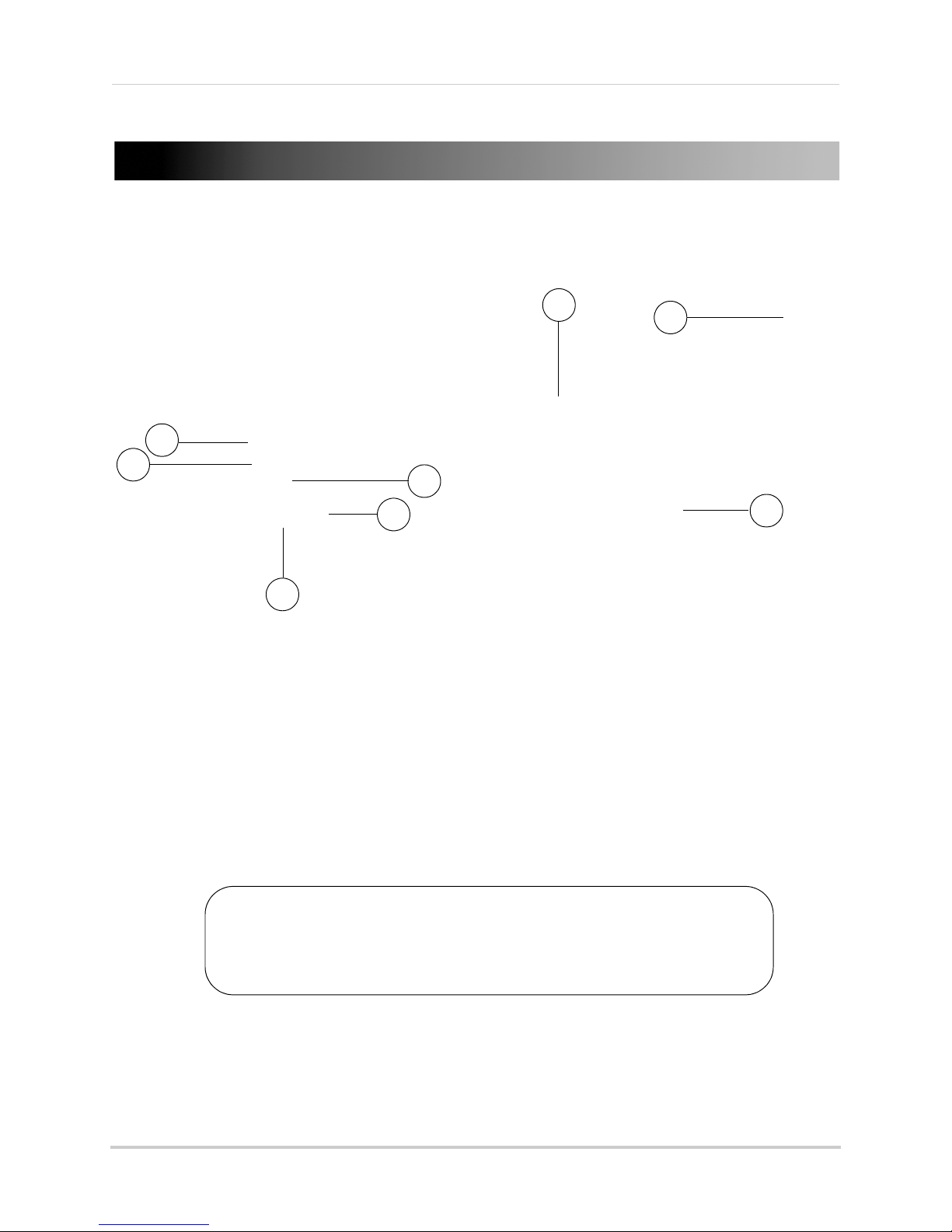
Features
• 7"/9” digital LCD display
• Simple installation. No video cables required
1
2
• Integrated digital video recorder
• Multiple recording options: manual, motion or schedule
3
• Time and date stamped recordings for easy retrieval
• Front panel feather touch controls
• Dual motion sensing technology with sensitivity level settings
• Digital picture frame with the ability to upload your own pictures for discreet monitoring
4
• Review recordings and watch live video at the same time with Picture-In-Picture feature
• Built-in camera light filter provides accurate color reproduction in all lighting conditions
• 2-Way Audio for Intercom usage
• Night viewing up to 40ft (12m) away
• Install cameras indoors or outdoors
5
6
• View up to 4 cameras at the same time or in sequence
• Up to 180ft indoor/650ft outdoor wireless range
7
• AV Output for viewing on a larger screen (e.g. TV)
• Tabletop, wall or under-counter mountable monitor
• View remotely via Skype™*
1. LCD display size varies depending on model.
2. Cameras require a local power outlet.
3. Local viewing up to 4 cameras simultaneously. Local recording and playback of one camera at a time or all 4
cameras simultaneously on one screen (Quad view).
4. Ability to upload your own pictures supported using a PC only. Default covert function (blank screen) available as
an alternative option.
5. Stated IR Illumination range is based on ideal conditions. Actual range and image clarity depends on installation
location, viewing area and light reflection/absorption level of object.
6. Weather-resistant. Not intended for direct exposure to rain or snow. For outdoor applications install under shelter
protected from the elements.
7. Based on line of sight. Actual range will vary depending on obstructions.
* No recurring charges. Internet connection required on connected PC or Mac. Remote connection requires driver
installation on home PC (CD included), a wired USB connection between the monitor and PC (USB cable included)
and a high speed internet connection. PC must be turned ON and Skype™ application must be running. Remote
viewing is limited to a single camera and is not selectable remotely.
viii
Page 11

Table of Contents
Getting started. . . . . . . . . . . . . . . . . . . . . . . . . . . . . . . . . . . . . . . . . . . . . . . . . . . . . . . 1
Installing the camera . . . . . . . . . . . . . . . . . . . . . . . . . . . . . . . . . . . . . . . . . . . . . . . . . . . . . . . . . . . 2
Setting up the receiver . . . . . . . . . . . . . . . . . . . . . . . . . . . . . . . . . . . . . . . . . . . . . . . . . . . . . . . . . . 4
Step 1 of 3: Installing the antenna . . . . . . . . . . . . . . . . . . . . . . . . . . . . . . . . . . . . . . . . . . . . . . . . . . . . . . . . 4
Step 2 of 3: Turning on the receiver . . . . . . . . . . . . . . . . . . . . . . . . . . . . . . . . . . . . . . . . . . . . . . . . . . . . . . 4
Step 3 of 3: Inserting the SD card . . . . . . . . . . . . . . . . . . . . . . . . . . . . . . . . . . . . . . . . . . . . . . . . . . . . . . . . 4
Camera overview . . . . . . . . . . . . . . . . . . . . . . . . . . . . . . . . . . . . . . . . . . . . . . . . . . . . 5
Receiver overview. . . . . . . . . . . . . . . . . . . . . . . . . . . . . . . . . . . . . . . . . . . . . . . . . . . . 6
Front panel buttons . . . . . . . . . . . . . . . . . . . . . . . . . . . . . . . . . . . . . . . . . . . . . . . . . . . . . . . . . . . . .6
Back of receiver . . . . . . . . . . . . . . . . . . . . . . . . . . . . . . . . . . . . . . . . . . . . . . . . . . . . . . . . . . . . . . . . 7
LED Indicators on the LCD receiver . . . . . . . . . . . . . . . . . . . . . . . . . . . . . . . . . . . . . . . . . . . . . . . . 8
Using the system. . . . . . . . . . . . . . . . . . . . . . . . . . . . . . . . . . . . . . . . . . . . . . . . . . . . . 9
Understanding the on-screen display . . . . . . . . . . . . . . . . . . . . . . . . . . . . . . . . . . . . . . . . . . . . . . 9
Navigating menu screens . . . . . . . . . . . . . . . . . . . . . . . . . . . . . . . . . . . . . . . . . . . . . . . . . . . . . . .10
Viewing modes . . . . . . . . . . . . . . . . . . . . . . . . . . . . . . . . . . . . . . . . . . . . . . . . . . . . . . . . . . . . . . . .11
Auto Sequence Viewing mode . . . . . . . . . . . . . . . . . . . . . . . . . . . . . . . . . . . . . . . . . . . . . . . . . . . . . . . . . . 11
Quad mode . . . . . . . . . . . . . . . . . . . . . . . . . . . . . . . . . . . . . . . . . . . . . . . . . . . . . . . . . . . . . . . . . . . . . . . . . . 11
Digital Zoom . . . . . . . . . . . . . . . . . . . . . . . . . . . . . . . . . . . . . . . . . . . . . . . . . . . . . . . . . . . . . . . . . . 12
Using the Intercom (two-way audio) . . . . . . . . . . . . . . . . . . . . . . . . . . . . . . . . . . . . . . . . . . . . . .12
Two-way audio volume . . . . . . . . . . . . . . . . . . . . . . . . . . . . . . . . . . . . . . . . . . . . . . . . . . . . . . . . . . . . . . . . 13
Using AV output . . . . . . . . . . . . . . . . . . . . . . . . . . . . . . . . . . . . . . . . . . . . . . . . . . . . . . . . . . . . . . . 13
Setting the time . . . . . . . . . . . . . . . . . . . . . . . . . . . . . . . . . . . . . . . . . . . . . . . . . . . . . 14
Recording . . . . . . . . . . . . . . . . . . . . . . . . . . . . . . . . . . . . . . . . . . . . . . . . . . . . . . . . . . 15
Recording prerequisites . . . . . . . . . . . . . . . . . . . . . . . . . . . . . . . . . . . . . . . . . . . . . . . . . . . . . . . . . . . . . . . 15
Minimum recording times on SD cards . . . . . . . . . . . . . . . . . . . . . . . . . . . . . . . . . . . . . . . . . . . . . . . . . . 15
Recording mode summary . . . . . . . . . . . . . . . . . . . . . . . . . . . . . . . . . . . . . . . . . . . . . . . . . . . . . . . . . . . . . 16
Manual recording . . . . . . . . . . . . . . . . . . . . . . . . . . . . . . . . . . . . . . . . . . . . . . . . . . . . . . . . . . . . . .17
Schedule recording . . . . . . . . . . . . . . . . . . . . . . . . . . . . . . . . . . . . . . . . . . . . . . . . . . . . . . . . . . . . 17
Stopping Schedule Recording . . . . . . . . . . . . . . . . . . . . . . . . . . . . . . . . . . . . . . . . . . . . . . . . . . . . . . . . . . 18
Motion recording . . . . . . . . . . . . . . . . . . . . . . . . . . . . . . . . . . . . . . . . . . . . . . . . . . . . . . . . . . . . . . 19
Setting up motion recording . . . . . . . . . . . . . . . . . . . . . . . . . . . . . . . . . . . . . . . . . . . . . . . . . . . . . . . . . . . 19
Configuring motion recording duration . . . . . . . . . . . . . . . . . . . . . . . . . . . . . . . . . . . . . . . . . . . . . . . . . . 20
Selecting Single Channel or 4 Channel motion recording . . . . . . . . . . . . . . . . . . . . . . . . . . . . . . . . . . . 21
Configuring video motion detection . . . . . . . . . . . . . . . . . . . . . . . . . . . . . . . . . . . . . . . . . . . . . . . . . . . . . . 21
Configuring the recording quality . . . . . . . . . . . . . . . . . . . . . . . . . . . . . . . . . . . . . . . . . . . . . . . . . . . . . . . 22
Enabling/disabling overwrite . . . . . . . . . . . . . . . . . . . . . . . . . . . . . . . . . . . . . . . . . . . . . . . . . . . . . . . . . . . 22
Playback . . . . . . . . . . . . . . . . . . . . . . . . . . . . . . . . . . . . . . . . . . . . . . . . . . . . . . . . . . . 23
Video playback . . . . . . . . . . . . . . . . . . . . . . . . . . . . . . . . . . . . . . . . . . . . . . . . . . . . . . . . . . . . . . . .23
Controlling playback . . . . . . . . . . . . . . . . . . . . . . . . . . . . . . . . . . . . . . . . . . . . . . . . . . . . . . . . . . . . . . . . . . 24
Picture-in-Picture mode . . . . . . . . . . . . . . . . . . . . . . . . . . . . . . . . . . . . . . . . . . . . . . . . . . . . . . . . . . . . . . 24
Image playback . . . . . . . . . . . . . . . . . . . . . . . . . . . . . . . . . . . . . . . . . . . . . . . . . . . . . . . . . . . . . . .25
Deleting video or image files . . . . . . . . . . . . . . . . . . . . . . . . . . . . . . . . . . . . . . . . . . . . . . . . . . . . 25
ix
Page 12

Screen Saver (digital picture frame) mode . . . . . . . . . . . . . . . . . . . . . . . . . . . . . . 28
Uploading images to the SD card (PC only) . . . . . . . . . . . . . . . . . . . . . . . . . . . . . . . . . . . . . . . . 28
Configuring Screen Saver mode . . . . . . . . . . . . . . . . . . . . . . . . . . . . . . . . . . . . . . . . . . . . . . . . .31
Activating Screen Saver mode . . . . . . . . . . . . . . . . . . . . . . . . . . . . . . . . . . . . . . . . . . . . . . . . . . . 32
Motion detection in Screen Saver mode . . . . . . . . . . . . . . . . . . . . . . . . . . . . . . . . . . . . . . . . . . . . . . . . . . 32
Screen Saver with motion recording . . . . . . . . . . . . . . . . . . . . . . . . . . . . . . . . . . . . . . . . . . . . . . . . . . . . . 32
Pairing/adding cameras. . . . . . . . . . . . . . . . . . . . . . . . . . . . . . . . . . . . . . . . . . . . . . 33
Settings. . . . . . . . . . . . . . . . . . . . . . . . . . . . . . . . . . . . . . . . . . . . . . . . . . . . . . . . . . . . 34
Alarm Volume . . . . . . . . . . . . . . . . . . . . . . . . . . . . . . . . . . . . . . . . . . . . . . . . . . . . . . . . . . . . . . . . . . . . . . . 34
Video Output . . . . . . . . . . . . . . . . . . . . . . . . . . . . . . . . . . . . . . . . . . . . . . . . . . . . . . . . . . . . . . . . . . . . . . . . 34
Auto Mute . . . . . . . . . . . . . . . . . . . . . . . . . . . . . . . . . . . . . . . . . . . . . . . . . . . . . . . . . . . . . . . . . . . . . . . . . . . 35
Format Memory . . . . . . . . . . . . . . . . . . . . . . . . . . . . . . . . . . . . . . . . . . . . . . . . . . . . . . . . . . . . . . . . . . . . . 35
Default Settings . . . . . . . . . . . . . . . . . . . . . . . . . . . . . . . . . . . . . . . . . . . . . . . . . . . . . . . . . . . . . . . . . . . . . . 36
Camera On/Off. . . . . . . . . . . . . . . . . . . . . . . . . . . . . . . . . . . . . . . . . . . . . . . . . . . . . . 37
Brightness . . . . . . . . . . . . . . . . . . . . . . . . . . . . . . . . . . . . . . . . . . . . . . . . . . . . . . . . . 37
Viewing your camera remotely using Skype™ . . . . . . . . . . . . . . . . . . . . . . . . . . . 38
How it works . . . . . . . . . . . . . . . . . . . . . . . . . . . . . . . . . . . . . . . . . . . . . . . . . . . . . . . . . . . . . . . . . . 38
System requirements . . . . . . . . . . . . . . . . . . . . . . . . . . . . . . . . . . . . . . . . . . . . . . . . . . . . . . . . . .38
Connecting to Skype on a PC . . . . . . . . . . . . . . . . . . . . . . . . . . . . . . . . . . . . . . . . . . . . . . . . . . . .39
Step 1 of 6: Installing the camera driver for PC . . . . . . . . . . . . . . . . . . . . . . . . . . . . . . . . . . . . . . . . . . . . 39
Step 2 of 6: Connecting the video monitor to the PC . . . . . . . . . . . . . . . . . . . . . . . . . . . . . . . . . . . . . . . . 40
Step 3 of 6: Creating a Skype account . . . . . . . . . . . . . . . . . . . . . . . . . . . . . . . . . . . . . . . . . . . . . . . . . . . . 40
Step 4 of 6: Configuring Skype . . . . . . . . . . . . . . . . . . . . . . . . . . . . . . . . . . . . . . . . . . . . . . . . . . . . . . . . . . 42
Step 5 of 6: Send a contact request . . . . . . . . . . . . . . . . . . . . . . . . . . . . . . . . . . . . . . . . . . . . . . . . . . . . . . 43
Step 6 of 6: Test the connection . . . . . . . . . . . . . . . . . . . . . . . . . . . . . . . . . . . . . . . . . . . . . . . . . . . . . . . . . 44
Connecting to Skype on a Mac . . . . . . . . . . . . . . . . . . . . . . . . . . . . . . . . . . . . . . . . . . . . . . . . . . .45
Step 1 of 6: Installing the camera driver for Mac OS . . . . . . . . . . . . . . . . . . . . . . . . . . . . . . . . . . . . . . . . 45
Step 2 of 6: Connecting the video monitor or receiver to your computer . . . . . . . . . . . . . . . . . . . . . . . 45
Step 3 of 6: Creating a Skype account . . . . . . . . . . . . . . . . . . . . . . . . . . . . . . . . . . . . . . . . . . . . . . . . . . . . 46
Step 4 of 6: Configuring Skype . . . . . . . . . . . . . . . . . . . . . . . . . . . . . . . . . . . . . . . . . . . . . . . . . . . . . . . . . . 47
Step 5 of 6: Send a contact request . . . . . . . . . . . . . . . . . . . . . . . . . . . . . . . . . . . . . . . . . . . . . . . . . . . . . . 48
Step 6 of 6: Test the connection . . . . . . . . . . . . . . . . . . . . . . . . . . . . . . . . . . . . . . . . . . . . . . . . . . . . . . . . . 49
If you do not have a Skype account... . . . . . . . . . . . . . . . . . . . . . . . . . . . . . . . . . . . . . . . . . . . . . .50
Changing the camera view on Skype . . . . . . . . . . . . . . . . . . . . . . . . . . . . . . . . . . . . . . . . . . . . . . 51
Viewing a camera on your smart phone or tablet . . . . . . . . . . . . . . . . . . . . . . . . . . . . . . . . . . . 52
Supported apps & devices . . . . . . . . . . . . . . . . . . . . . . . . . . . . . . . . . . . . . . . . . . . . . . . . . . . . . . . . . . . . . 52
Prerequisites . . . . . . . . . . . . . . . . . . . . . . . . . . . . . . . . . . . . . . . . . . . . . . . . . . . . . . . . . . . . . . . . . . . . . . . . 52
Viewing your camera on iPhone . . . . . . . . . . . . . . . . . . . . . . . . . . . . . . . . . . . . . . . . . . . . . . . . . . . . . . . . 52
Viewing your camera on iPad . . . . . . . . . . . . . . . . . . . . . . . . . . . . . . . . . . . . . . . . . . . . . . . . . . . . . . . . . . . 53
Viewing your camera on an Android smartphone or tablet . . . . . . . . . . . . . . . . . . . . . . . . . . . . . . . . . . . 53
Technical specifications . . . . . . . . . . . . . . . . . . . . . . . . . . . . . . . . . . . . . . . . . . . . . . 54
Strengthening the range of the wireless signal . . . . . . . . . . . . . . . . . . . . . . . . . . 55
Power failure indicator . . . . . . . . . . . . . . . . . . . . . . . . . . . . . . . . . . . . . . . . . . . . . . 57
Mounting the LCD receiver . . . . . . . . . . . . . . . . . . . . . . . . . . . . . . . . . . . . . . . . . . . 58
Troubleshooting . . . . . . . . . . . . . . . . . . . . . . . . . . . . . . . . . . . . . . . . . . . . . . . . . . . . 59
Frequently asked questions . . . . . . . . . . . . . . . . . . . . . . . . . . . . . . . . . . . . . . . . . . 60
x
Page 13

Getting started
Two way audio outdoor
camera*
LCD monitor / wireless
receiver*
SD memory card**
Power adapters for receiver
and camera*
AV cable
Camera mounting stand* Under the counter
mounting kit
Wireless antennas (for
receiver and camera)*
Mounting kit(s)*
*Configuration may vary by model.
USB cable
Software CD
**Optional SD card. Consult your package for content details.
The system includes the following components:
CAMERA CONFIGURATION, MONITOR SIZE, AND NUMBER OF ACCESSORIES MAY VARY BY
MODEL. PLEASE REFER TO YOUR PACKAGE FOR SPECIFIC DETAILS.
CHECK YOUR PACKAGE TO CONFIRM THAT YOU HAVE RECEIVED THE COMPLETE SYSTEM.
1
Page 14
Installing the camera
Cameras are suitable for outdoor installation, but are weather resistant,
not weather proof. Cameras are not intended for direct exposure to
rain or snow. For outdoor applications, install under shelter protected
from the elements, such as beneath roof eaves. The diagram below
shows an example of an ideal location for outdoor placement.
Example ideal outdoor location
Installation Tips:
• Before you install the camera, plan where and how it will be positioned, and where you will
route the cable that connects the camera to the power adapter.
• Before starting permanent installation, have another person check the camera image on the
monitor when camera is positioned in the same place it will be permanently installed.
• It is recommended to ensure a clear line-of-sight between the camera and receiver and to
limit the amount of obstructions, such as walls and tree branches, between the camera and
receiver. Walls made of heavy building materials such as brick or concrete will significantly
reduce signal range.
• If the signal will have to pass through a wall, placing the receiver or camera next to a window
will improve the signal strength.
• Do not install the camera pointing out of a window. The nighttime picture will be unusable
due to reflection from the night vision LED’s.
• The cameras are pre-paired so they work out of the box. Each camera has a channel number
sticker indicating what channel they are paired to. If you have purchased additional cameras,
you will need to pair them to the receiver, see “Pairing/adding cameras” on page 33.
11
To install the camera:
1 Use the included mounting screws to mount the stand to the mounting surface:
• Mark the position of the screw holes on the wall.
• Drill holes and insert the drywall plugs as needed.
• Firmly attach the stand to the wall using the provided screws.
2
Page 15

2 Twist the antenna clockwise onto the antenna port on the side of the camera.
Connect antenna
Connect camera stand
Tighten thumb
screws
Peel protective film off
camera
3 Attach the camera to the mounting stand. Adjust the angle of the camera until the desired
view is set. Tighten the thumbscrews to secure the desired camera position.
4 Connect the black power cable extending from the camera to the cable of the power adapter,
and plug in the power adapter to an outlet or surge protector. Make sure the power
connector is fully pushed in to avoid water getting in the plug.
5 Remove the protective film from the front of the camera. If the film is not removed, it will
bl
ock the built-in microphone and potentially affect the quality of the picture.
3
Page 16

Getting started
Connect antenna to receiver
Setting up the receiver
Step 1 of 3: Installing the antenna
Twist the antenna clockwise onto the receiver’s antenna jack located on the back of the
receiver.
Step 2 of 3: Turning on the receiver
1 Connect the cable from the power adapter to the 5V DC port on the bottom panel of the
receiver. Plug in the power adapter to an outlet or surge protector.
2 Slide the power switch on the rear panel to the "ON" position.
Tips:
• Place the receiver in a location that will have a clear reception to your camera. Try to maintain
line-of-sight and minimize the
• Adjust the antenna on the receiver as necessary to provide the clearest reception.
number of obstructions between the camera and receiver.
Step 3 of 3: Inserting the SD card
The SD card allows you to store video footage captured by the camera. Push the SD card into
the SD card slot on the LCD receiver until you hear a "click." The card will not be flush when
completely inserted.
NOTE: The receiver is compatible with most major brands of SD card up to 32 GB. For
recording times on SD cards, see “Minimum recording times on SD cards” on
page 15.
4
Page 17
Camera overview
2
1
3
5
6
7
8
4
This camera includes an Auto Mechanical IR Cut Filter. When the camera
changes between day mode and night vision mode, an audible clicking noise
may be heard coming from the camera. This clicking is normal, and indicates
that the camera filter is working.
ATTENTION
Camera overview
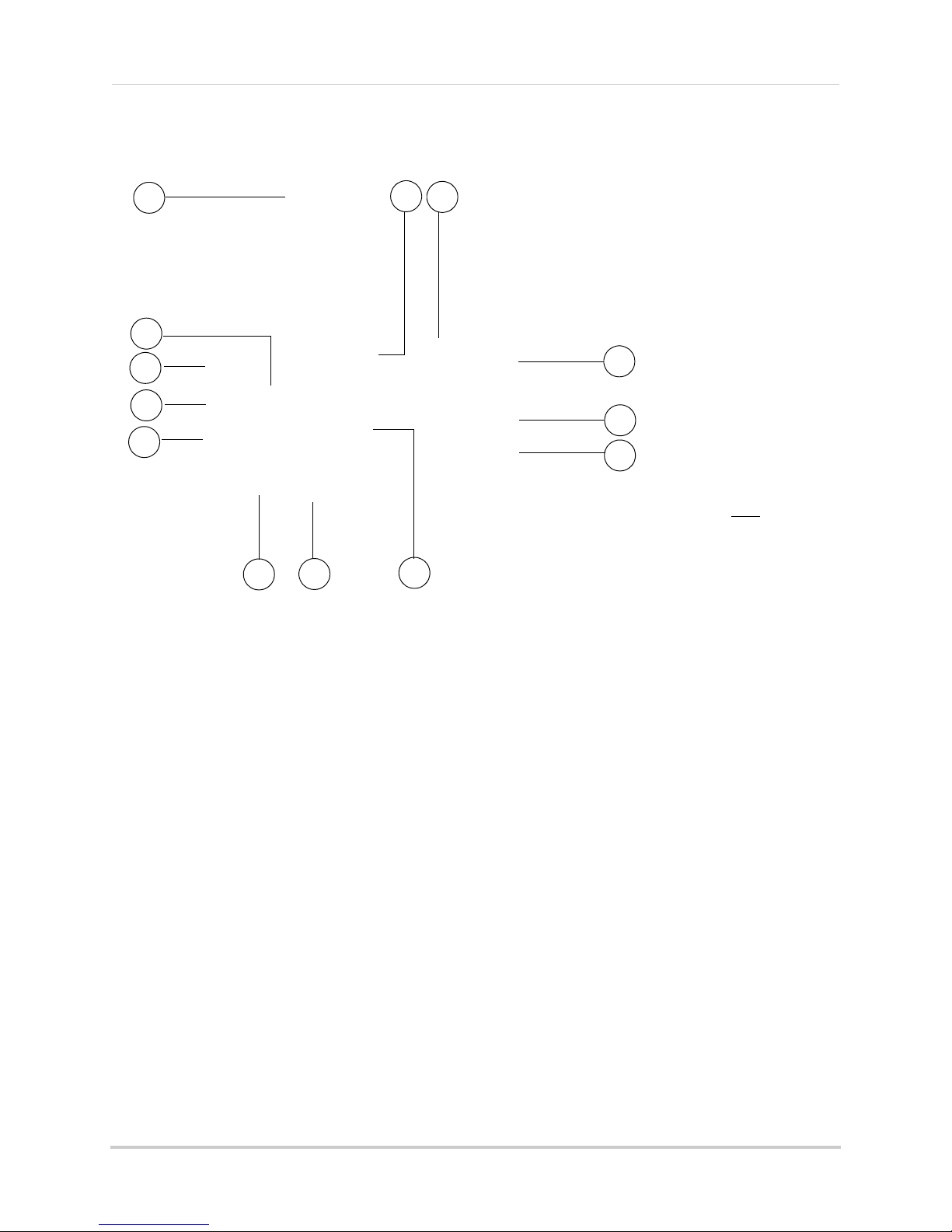
1 Microphone: Built-in microphone.
2 Lens: Camera
3 PIR Sensor: Pa
4 Speaker: Speak
lens.
ssive IR motion sensor.
er for intercom.
5 Night Vision IR: Night vision IR LEDs.
6 Pair: P
7 Antenna: Wir
8 Power Cable: Connect the included
airing button. For more details, see “Pairing/adding cameras” on page 33.
eless antenna.
power adapter to the cable extending from the camera.
5
Page 18

Receiver overview
Front panel buttons
Receiver overview
Front panel buttons
Button Function
: Motion Recording
: Manual Recording
: Menu
/ : Volume Control
/ : Channel Select Change channel. Scroll up / down in menus.
: OK
: Quad / Sequence Mode
: Screen Saver Mode
: Talk
Activate/deactivate Motion Recording.
Start/stop Manual Recording.
Open Main Menu. Return to previous menu / exit menus.
Increase / decrease volume on receiver. Scroll left / right
in menus.
In menus, confirm selection. While viewing, open Playback mode to view recorded video or uploaded images.
Switch between Sequence and Quad (4-channel) viewing
mode.
Activate/deactivate Screen Saver mode. see “Screen
Saver (digital picture frame) mode” on page 28.
Activate Intercom (2-way-audio).
6
Page 19
Back of receiver
1
2
3
4
5
6
8
10
12
13
7
9
11
*LW2930 Series
uses a slide switch
located on the side
panel
LW2730 Series
Receiver overview
1 Wireless Antenna: Position the antenna as needed for best reception.
2 Mounting Hol
e: Attach the included under-the-counter mount to mount the LCD receiver
underneath a counter/cupboard or to a wall.
3 Speak
4 SD Car
5 USB P
er: Speaker for two-way audio.
d Slot: Insert up to a 32GB SD card.
ort: Used for Skype connectivity. For details, see “Viewing your camera remotely using
Skype™” on page 38.
6 AV
7 Rec
8 Powe
9 Mi
10 AV
11 Joys
OUT: Connect the Audio/Video cable to view video on an external TV or monitor (optional).
eiver Stand
r Input (DC5V): Connect the included power adapter.
crophone: Microphone for two-way audio.
: Press to send the image to a connected TV or monitor (AV cable required).
NOTE: Scr
een Saver mode is not available if using AV-out.
tick: Deletes files during Playback mode. See “Deleting video or image files” on page 25.
12 ZOOM: Pr
13 Powe
ess to enable/disable Digital Zoom mode.
r: Slide switch to turn the LCD receiver ON/OFF*.
7
Page 20

Receiver overview
FULL MOTION
LED indicators
NEW SCAN
LED Indicators on the LCD receiver
Use the LED indicators on the LCD receiver to observe the status of the receiver, cameras, and
SD card.
The blue lights indicate the following:
• NEW: A new video file has been recorded to the SD card.
• FULL:
NOTE: The "Full" light will only appear if Ov
The SD card is full.
erwrite is disabled. For details, see “Enabling/
disabling overwrite” on page 22.
• MOTION:
Motion detection recording is enabled.
• SCAN: Screen Saver mode ("Scan" mode) is enabled.
8
Page 21
Using the system
1
2 3 4 5 6 7
9
8
2-160602.AVI
Hour
(24-hour)
Minute
Seconds
Camera number
File extension (.AVI)
Using the system
By default, the camera(s) included with your system are automatically paired to the wireless
receiver. The camera(s) and receiver will communicate with each other once they are powered
on.
NOTE: Power on the cameras before powering on the receiver.
Understanding the on-screen display
With camera 1 properly connected and powered on, the system displays a single channel
full-screen live view of the camera.
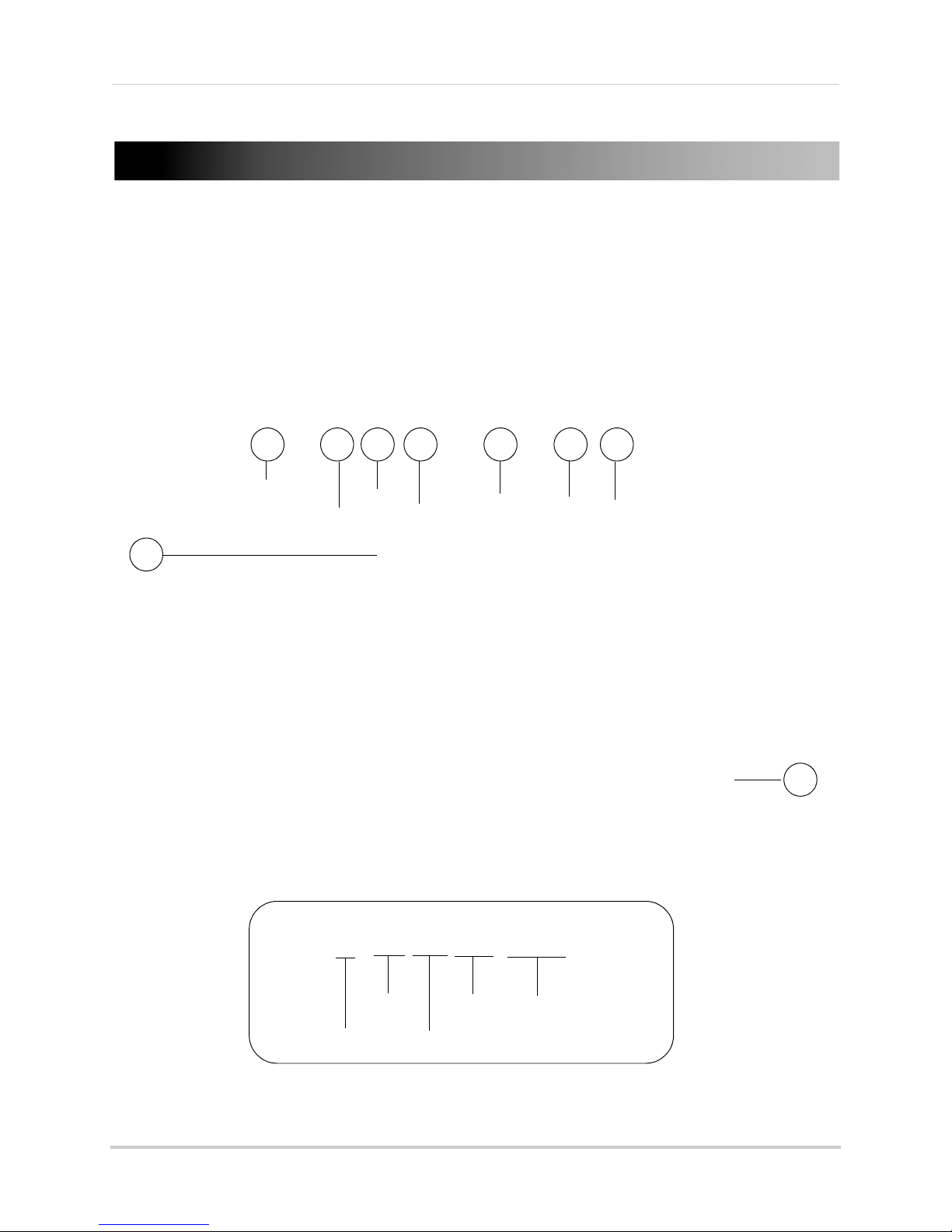
1 File Name: The name of the file currently being recorded. This file will appear in the file list
on the SD card. The Recording File stamp indicates the hour, minutes, and seconds that the
system started recording.
9
Page 22

Using the system
SD card writing data
Main Menu
2 Signal Indicator: The signal indicator shows the strength of the signal being received from
the camera. The number of bars in the Signal Indicator shows the strength of the signal. One,
or no bars indicates the signal is poor, and 4 bars indicate a very strong signal. The signal
indicator is not shown during quad mode.
o
NOTE: If the signal is l
w (e.g. 1 or 2 bars) adjust the antennas, or reposition the cameras
or receiver for best performance.
3 Cam
era indicator: Displays the
4 File Icon: Flashes
yellow when writing data to the SD card.
camera you are presently viewing.
5 SD Card icon: A white "SD" icon displays that an SD card is inserted in the wireless receiver. A
red icon indicates the SD card is full.
erwrite icon: Indic
6 Ov
ates Overwrite mode is on, which means the system will overwrite the
oldest recordings when the SD card is full. For details, see “Enabling/disabling overwrite” on
page 22.
7 Power Failure icon: Indic
ates a power failure has occurred on the system during recording.
You may need to manually restore recording/viewing modes on the system, and recordings up
to 10 minutes before the power failure occurred will not be saved. For more details, see
“Power failure indicator” on page 57.
8 Rec
ording Indicator: "
REC" appears when recording is in progress.
9 Time Stamp: The current date and time on the system.
Navigating menu screens
Use the system menus to configure settings.
• Press to open the Main Menu.
• Press / to move the cursor left and right.
• Press / to move the cursor up and down.
• Press OK to open sub-menus and confirm/save menu
selections.
• Press to exit menus without saving changes.
10
Page 23
Using the system
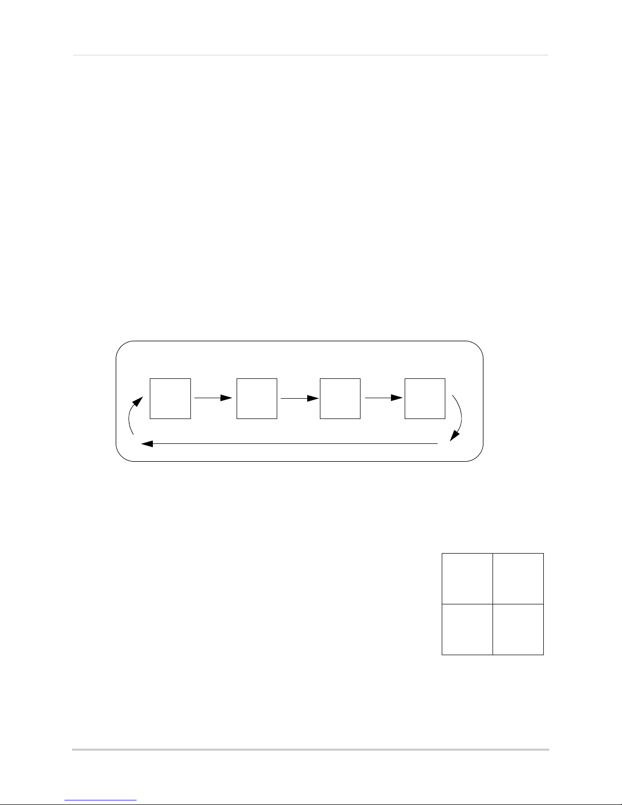
Auto Sequence Example
CH 1 CH 2 CH 4CH 3
CH1
CH2
CH3
CH4
Quad mode
Viewing modes
There are four different viewing modes available on the system: single channel viewing, Auto
Sequence Viewing mode (view individual channels automatically in sequence), Quad mode, and
Screen Saver mode (for details, see “Screen Saver (digital picture frame) mode” on page 28).
To change viewing modes:
• Press to select between Quad mode and Auto Sequence viewing mode.
OR
• Press / to switch between channels 1~4 in single channel view.
ult, Auto Sequence Viewing mode is enabled when you first power on the
NOTE: By def
Auto Sequence Viewing mode
Auto Sequence Viewing Mode switches between connected channels in full-screen.
a
system, and when you exit Screen Saver mode.
To enable Auto Sequence:
• Press until a single channel is shown on screen. The monitor automatically switches
through connected channels.
Quad mode
Use Quad mode to view up to four cameras simultaneously.
To select Quad mode:
1 Press .
NOTE: Using Quad mode wi
mode because it allows you to record the entire screen (up
to 4 cameras) when motion is detected by one of the cameras.
For more details, see “Motion recording” on page 19.
th Motion Recording is a useful recording
11
Page 24

Using the system
Zoom button
Zoom is activated
Press UP/DOWN/LEFT/RIGHT to
look at different parts of the image
Digital Zoom
The Digital Zoom feature allows you to zoom in 2x on your cameras during live viewing. This is
useful if you need a closer look at something happening far away from the cameras.
To use digital zoom:
1 Select the desired camera in full-screen mode (press UP/DOWN to select the channel) and
press the ZOOM button on the rear panel of the wireless receiver to zoom in.
2 When Digital Zoom is activated, a x2 icon appears on the screen. Press UP/DOWN/LEFT/
RIGHT on the front panel of the monitor to look at different parts of the image.
3 Press the ZOOM button again to exit digital zoom.
Using the Intercom (two-way audio)
Use the Intercom feature for two-way communication between the wireless receiver and the
camera. Talk to the person at the camera from behind closed doors for added security.
NOTE: Please make sure the camera(s) is properly connected prior to using the Intercom.
To use the Intercom:
1 Select the desired camera in full-screen mode (press UP/DOWN to select the channel) and
press and hold the
2 Talk in a normal speaking voice close to the LCD screen (approximately 12 in. / 30 cm).
3 Release the
12
button to hear a response from the camera.
button. An audio icon appears on-screen.
Page 25

Using the system
2-way audio volume
AV button
AV Out port
Two-way audio volume
The two-way audio volume is different from the alarm/buzzer volume found in the Main Menu
>Settings>Alarm Volume).
(
To change two-way audio volume:
• From live viewing, press to increase the system volume or press to decrease the
system volume.
• The volume icons on the screen indicate the volume of sound coming from the cameras.
NOTE: You cannot adjust the volume of the camera speakers.
Using AV output
Use the included AV cable to connect the system to a TV for viewing on a larger screen
To enable AV output:
1 Connect the single end of the AV cable to the AV Out port on the rear panel of the wireless
receiver. Connect the yellow and white RCA ends to matching inputs on your TV. Select the
corresponding input on your TV (commonly referred to as AV, Input, Video, etc.).
2 Press the AV button on the rear panel to switch the wireless receiver to AV mode. The monitor
will turn off. After a few seconds, the image from the monitor will be displayed on the TV.
NOTE: If you need to change the AV output to PAL format (for European TV’s), see “Video
Output” on
page 34.
13
Page 26

Setting the time
Date & Time menu
Date and time
2012/09/22
13:36:49
Setting the time
It is highly recommended to set the time on the system
prior to recording. You need to set
time in order to use Schedule Recording.
To set the time:
1 Press to open the main menu. Press left and
the correct date and
right to select
2 Select Date &
3 Press RIGHT/
DOWN to change the year, month, day, hour, minutes,
and seconds.
NOTE: The
4 Press OK t
5 Press
NOTE: There is no
on the system. DST must be set manually if
necessary.
Settings and press the OK button.
Time and press the OK button.
LEFT to move the cursor; press UP/
system uses a 24-hour clock only.
o save your settings.
to close any remaining menu windows.
daylight savings time (DST) setting
14
Page 27

Recording
The following recording modes are available on the system: Manual Recording, Schedule
Recording, and Motion Recording. The system can record video to an SD card one channel at
a time or record the entire screen in Quad mode.
Recording prerequisites
• An SD card must be inserted in the wireless receiver in order to record. You should always
format the SD card prior to initial recording. For details, see “Format Memory” on page 35.
NOTE: Recording overrides other actions on the receiver. You must stop recording on the
sys
tem in order to perform other actions, such as opening the Main Menu, Quad
mode, etc.
Recording
Minimum recording times on SD cards
The system supports SD cards up to 32 GB. Use the table below to help you estimate the
recording times on various sizes of SD cards. Times shown are in hours and minutes.
SD Card
Capacity
1 GB 2:00 1:19
2 GB 3:52 2:34
4 GB 8:04 5:21
8 GB 15:36 10:21
16 GB 30:48 20:27
32 GB 62:56 41:47
NOTE: The sys
Using higher class SD memory does not ensure better performance.
Single Channel
Recording
em is compatible with SD High Capacity (SDHC) cards, minimum Class 2.
t
4 Channel
Recording
15
Page 28

Recording
Recording mode summary
Mode Description How to Operate
MANUAL
RECORDING
SCHEDULE
RECORDING
MOTION
RECORDING (AUTO)
SCREEN SAVER +
MOTION RECORDING
• Continuous recording from
one camera or entire screen
in Quad mode
• Continuous recording from
one camera, from Auto
Sequence Viewing mode
(system records cameras in
sequence), or Quad or Screen
Saver mode (system records
all cameras in Quad mode)
according to a weekly
schedule
• System only records when
motion is detected by a
camera
• Compatible with Quad mode
(recommended)
• Compatible with Auto
Sequence Viewing mode
• Enable Screen Saver to
enable digital picture frame
mode or turn off the LCD
monitor when motion is not
detected
• You must upload images to
the SD card to use digital
picture frame mode (see
“Screen Saver (digital picture
frame) mode” on page 28). A
PC is required to upload
images to the SD card; Mac is
not supported for this
function
• Press the Record button ( )
to start/stop manual
recording
• ATTENTION: Turn off Motion
Recording to enable Schedule
Recording
• Enter a Start and Stop Time
for each day from
>Recording>
Schedule Record
• Press to start/stop
Motion Recording
• Press to start Motion
Recording
• Press to enable Screen
Saver mode
• Cannot enable Screen Saver
mode while the monitor is in
Quad mode
16
Page 29

Recording
Manual recording
Manual recording allows you to manually start/stop recording from one channel at a time or
the entire screen in Quad mode. You can also record while in Digital Zoom mode. For details
on using Digital Zoom, see “Digital Zoom” on page 12.
NOTE: During manual r
will stop automatically changing the channel.
ecording, you cannot change channels and Auto Sequence mode
To enable manual recording:
1 Press to start manual recording. "REC" appears on screen to indicate the system is
recording. The system will record from the camera that is on screen or it will record the
entire scr
2 Press
file is on the SD card.
een in Quad mode (black boxes will be shown for unused channels).
again to stop recording. "NEW" will appear on the LCD receiver indicating a new
When should I use manual recording?
• Recording of unexpected events or emergencies.
Schedule recording
Use schedule recording to have the system automatically record continuously from one
camera, from Auto Sequence Viewing mode (system records cameras in sequence), or from
the entire screen in Quad or Screen Saver mode (system records all cameras in Quad mode)
according to a selected start and stop time.
NOTE: You must set a recording schedule for each day you would like to use schedule
re
cording.
NOTE: Auto Sequence is available during schedule recording. However, the system will
ecord video of the sequence itself. Therefore you cannot playback video of individual
r
cameras.
Prerequisite:
Please ensure you have set the date and time on the receiver prior to setting a recording
schedule. See “Setting the time” on page 14.
Step 1 of 2: Set a recording schedule:
1 Press then select Recording and press OK.
2 Select Schedule Record and press OK.
3 Select a day of the week and press OK.
4 Press UP/D
End Time for recording on the selected day. Press
RIGHT/LEFT to move the cursor (yellow) between
hours and minutes for the Start Time and End
Time.
NOTE: The
OWN to configure the Start Time and
time uses a 24-hour clock.
17
Page 30

Recording
ATTENTION
Manual Recording or Motion Recording will override Schedule Recording.
If you wish to use Schedule Recording, you must ensure Manual Recording and Motion
Recording are disabled.
5 Move the cursor RIGHT/LEFT to select ON to enable the schedule or OFF to disable the
schedule and press OK to save.
6 Repeat s
finished, press
teps 3 through 5 for any additional days you would like to configure. When you are
until all menus are closed.
Step 2 of 2: Enable schedule recording
1 Disable ALL RECORDING on the system:
• If the system is in manual recording, press the Record button ( ) to stop recording.
• If the syst
appear on the wireless receiver.
2 Select the desired viewing mode:
• Sel
• Press to select between Auto Sequence Viewing mode and Quad mode.
em is in motion recording, press the Motion button ( ) until "MOTION" does NOT
ect a channel (1~4) by pressing UP/DOW
N.
• Press to enable Screen Saver mode (not available from Quad mode).
3 When the Start Time arr
ives, recording begins. The "REC" indicator appears on-screen.
Stopping Schedule Recording
When the Stop Time arrives, the system stops recording. If necessary, you can stop schedule
recording manually.
To stop Schedule Recording:
1 Press the Record button ( ) to stop schedule recording.
NOTE: If you stop schedule recording, you cannot resume schedule recording. You will need
t
o enter new Start and Stop times in the Schedule Record menu.
When should I use schedule recording?
• If the camera is pointed at an area with high traffic, such as a entry/exit or a road.
18
Page 31

Recording
A camera detects body heat movements, and
triggers the system to record.
The system detects movement in the image and
triggers recording.
PIR Motion Detection
Video Motion Detection
Motion recording
Use motion recording to have the system record only when motion is detected by one of the
cameras. The system can be set to record only from the camera that detects motion or from
the entire screen when the system is in Quad mode.
The system records motion in two ways. The cameras have
from body movements to detect movement up to a maximum range of 21 feet (6.5 meters). PIR
motion detection is extremely accurate at detecting movements from people and animals, but
the accuracy decreases in extremely hot environments approaching or exceeding human body
temperature (98.6°F / 37°C).
The system also uses video motion detection, which looks for changes in video images
(frames)
to detect motion. Video motion detection allows for motion detection beyond the
range of the PIR sensors and in extremely hot temperatures. Video motion detection is highly
accurate, but may trigger recording from changes in light or moving trees, leaves, etc. You can
set the sensitivity of video motion detection depending on your preferences (see “Configuring
video motion detection” on page 21).
built-in PIR sensor that track heat
Both PIR and video motion detection can be used at the same time for enhanced accuracy.
Setting up motion recording
Prerequisite:
• Insert an empty SD card into the LCD receiver.
To enable motion recording:
1 During live view, press .
• "MOTION" will light up on the LCD receiver.
2 Select the viewing mode. The viewing mode determines how motion recording operates.
• Enable Quad mode (recommended): Pr
when motion is detected, the system will display and record the triggered camera on-screen.
When motion recording is complete, the view will return to Quad mode. You can also configure
the system to record the entire screen during Quad mode (see “Selecting Single Channel or
4 Channel motion recording” on page 21).
ess until Quad mode is selected. By default,
19
Page 32

Recording
• Enable Auto Sequence Viewing mode: Press until a single channel is shown. When
motion is detected, the system will display and record the triggered camera on-screen. When
motion recording is over, Auto Sequence Viewing mode will continue as normal.
• Change channels manually: Press UP/DOWN to select a camera. The system will ONLY
record the selected camera; it will not record motion detected by other cameras.
• Enable Screen Saver mode: Press to enable screen saver mode. When motion is
detected, the system will display and record the triggered camera on-screen. When motion
recording is over, Screen Saver mode will continue as normal. For details on configuring
Screen Saver mode, see “Screen Saver (digital picture frame) mode” on page 28.
NOTE: By default, the system is set to record for 5 seconds after the triggered motion event.
For details on adjusting the motion recording time, see “Configuring motion
recording duration” on page 20 below.
3 Press
again to stop motion recording. "MOTION" will turn off on the receiver.
Recording tip:
If you are using more than one camera, it is highly recommended to use Quad mode with
Motion Recording. Quad mode allows you to see all four cameras at once. You can set the
system to record the entire screen, so that video from up to 4 cameras is recorded (to
configure 4 channel recording, see “Selecting Single Channel or 4 Channel motion recording”
on page 21).
Configuring motion recording duration
Use the Duration menu to set the length of the time
the system will record after motion is detected by
a camera.
To change the motion recording time:
1 Press , then select Recording and press OK.
2 Select Mot
3 Select Durat
4 Select 5 seconds
press OK.
ion Record and press OK.
ion and press OK.
, 15 Seconds, or 30 Seconds and
5 Press
20
until all menus are closed.
Page 33
Selecting Single Channel or 4 Channel motion recording
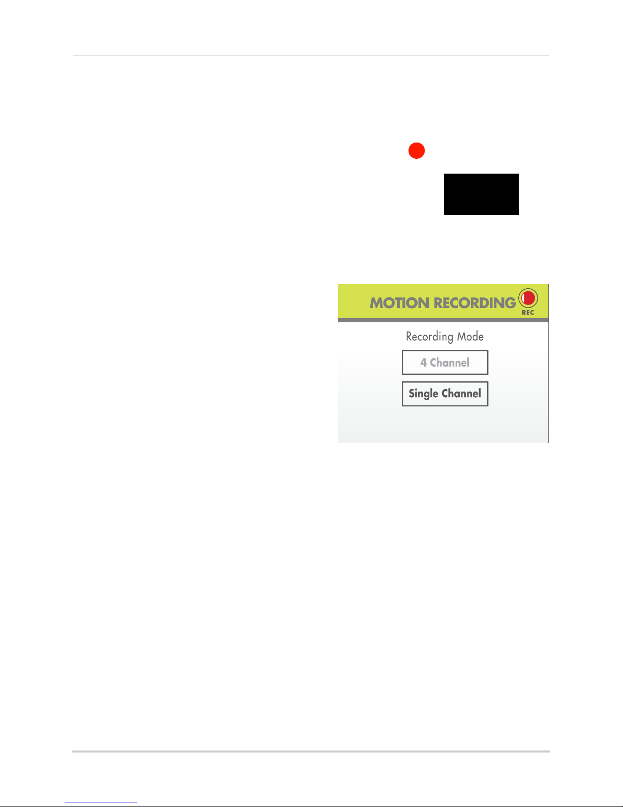
REC
4 Channel recording
Use the Mode menu to select between single
channel and 4 Channel motion recording.
When single channel recording is activated, the
monitor will switch to the camera that detects
motion and record from that channel only.
4 Channel recording will record the entire
screen
files recorded during 4 Channel recording will
start with the letter Q.
To select 4 Channel or single channel
recording:
1 Press , then select Recording and press
OK.
2 Select Motion Record and press OK.
during Quad mode (4-way-split). Videos
Recording
3 Select Mode and
4 Select 4 Channel re
recording and press OK.
5 Press
Quad mode must be selected to use 4 Channel
re
cording. To select Quad mode, press
repeatedly.
press OK.
cording or Single Channel
until all menus are closed.
Configuring video motion detection
Video motion detection looks for changes in video
images (frames) to detect motion. Video motion
detection allows for motion detection beyond the
range of the PIR sensors.
The drawback to video motion detection is that it
can be falsely triggered by changes in lighting
conditions or trees moving in the wind. You can
disable video motion detection or configure the
sensitivity using the menus.
For a description of the two motion detection
technologies used by
recording” on page 19.
the system, see “Motion
21
Page 34

Recording
To configure video motion detection:
1 Press , then select Video Motion Detection and press OK.
2 Select the camera you would like to configure and press OK.
3 Under Day, sele
sensitivity. Press DOWN to confirm.
4 Under Nig
5 Press OK to
6 Press
ct Off to disable video motion detection, or select Low, Medium, or High
ht, select Off to disable video motion detection or select Low sensitivity.
save your changes.
until all menus are closed.
Configuring the recording quality
The recording quality determines the quality of video
recorded.
1 Press
2 Select Qua
3 Select HIGH (
(360x240 QVGA resolution) quality and press OK to
save your settings.
4 Press
, then select Recording and press OK.
lity and press OK.
640x480 VGA resolution) or LOW
until all menus are closed.
Enabling/disabling overwrite
Use the overwrite feature to have the system
overwrite the oldest recorded data on the SD card
once the SD card is full.
To enable overwrite:
1 Press , then select Recording and press OK.
2 Select Over
3 Select
4 Press
If you do not enable Overwrite, the SD Card icon on the OSD will be red and a blue LED will light
up under
delete files from the SD card or insert a new SD card into the wireless receiver. For details see
“Deleting video or image files”
22
write and press OK.
Yes and press OK.
until all menus are closed. A icon is shown when overwrite is enabled.
"FULL" on the wireless receiver when the SD card is full. You will need to manually
on page 25.
Page 35

Playback
All recording must be stopped on the system prior to playing back saved files. The
system cannot record during Playback.
ATTENTION
Playback mode allows you to playback the recorded video files or view images that you have
uploaded to the SD card (for details, see “Uploading images to the SD card (PC only)” on
page 28). You
to your computer.
Video playback
To playback recorded video on the
system:
1 Stop all recording on the system.
can view videos or images directly on the system or by connecting the SD card
Playback
2 During live
menu opens.
3 Select the
4 Select a folder and press OK. F
labeled by date in
example,
2012). Select
level.
5 Select a file from the list and press
viewing, press OK. The File
VIDEO folder and press OK.
olders are
20121003
yyyymmdd
would be October 3,
format (for
[. .] and press OK to go up a
OK. The selected file loads and playback begins.
Tip:
Press LEFT and RIGHT to change pages to find video files quickly.
23
Page 36

Playback
Playback controls
Playback status
File name
Current video time /
length of video
00:00:00/00:00:50
1-112402
00:00:00/00:00:50
1-112402
Camera in
PIP mode
Controlling playback
Use UP/DOWN/LEFT/RIGHT to control video playback.
To control playback:
• LEFT: Rewind video / increase rewind speed. When you reach the beginning of the video,
playback is stopped, and you can press LEFT to skip to the previous video in the list.
• UP: Pause / Play video.
• RIGHT: Fast forward / increase fast forward speed. When you reach the end of the video,
playback is stopped, and you can press RIGHT to skip to the next video in the list.
• DOWN: Stop video. You can then press RIGHT/LEFT to select a different video file.
To exit playback:
• Press to return to the file list. Press repeatedly to return to live view.
Picture-in-Picture mode
While viewing recorded video, you can use Picture-in-Picture (PIP) mode to view your cameras
side-by-side in a smaller window.
NOTE: Recording is not available in
PIP mode.
To open Picture-in-Picture
mode:
• While playing a video, press to
open PIP mode. Your camera
appears in the top left corner.
NOTE: PIP mode disabl
controls.
• Press UP/DO
• Press again to close Picture-in-Picture mode.
WN to change the camera shown in Picture-in-Picture mode.
es playback
24
Page 37

Image playback
0001
Image file number
Press down on the joystick
to delete the file
If you have uploaded images to the SD card using PhotoRun, you can open them in Playback
mode. For instructions on how to upload files to the SD card, see “Uploading images to the SD
card (PC only)” on page 28.
NOTE: Recording and PIP mode is not available during image playback.
To open images in Playback mode:
1 Press OK.
2 Press DOWN to select the Photo folder and press
OK.
Playback
3 Sel
4 Select an image file and press OK to open
ect the desired image folder and press OK.
• Press LEFT/RIGHT t
o scroll through saved images.
it.
• Press to return to the file list. Press
repeatedly to return to live view.
NOTE: If you do not press any buttons, the system will
eturn to live view after 20 seconds.
r
Deleting video or image files
You can delete files on the SD card directly on the system. Delete files if you need to clear
space on the SD card (if Overwrite is disabled), or for your own file management purposes.
To delete files on the SD card:
1 From live viewing, press OK. The File menu opens.
2 Browse to the file you would like to delete. Press down on the joystick on the rear panel of the
stem.
sy
25
Page 38

Playback
091252_1
091252_1
100341_3
DELETE FILE
091430_1?
YES
NO
980KB
8112KB
2MB
100341_3
8112KB
2MB
091430_1
Do NOT delete folders on the SD card using your computer. Deleting folders may
affect your access to other files on the card or may affect normal operation of the SD
card with the system. If you want to delete the entire contents of the SD card, it is
highly recommended to format the card using the system. For details, see “Format
Memory” on page 35.
ATTENTION
The XviD, DivX, or FFDShow codec is required if attempting to view the video files in
Windows Media Player™. You can also view AVI files natively in other media players
such as VLC and DivX Player.
ATTENTION
3 A delete confirmation message appears, highlight YES and then press OK to delete the file.
4 Repeat the steps above for other files on the SD card.
NOTE: You cannot delete folders on the SD card using the system.
Viewing video directly from the SD card
You can view the saved video files on your computer (PC or Mac) by using an SD card reader
(not included). Saved video files are in AVI format.
NOTE: Some PCs and Macs may hav
computer's instruction manual for more details.
PC
To playback recorded video on a PC:
1 Remove the SD card from the wireless receiver by gently pushing on the SD card. The SD card
will pop out from the slot.
2 Insert the SD c
load the SD card as a new Removable Drive and an Autorun window opens.
26
ard into an SD card reader (not included) connected to your PC. Your PC should
e an SD card reader built-in. Please refer to your
Page 39

3 Click Open folder to view files or open the folder in Computer. You should see a folder
Additional codecs are required if attempting to view AVI files in QuickTime. VLC Player
is recommended for viewing AVI files on a Mac. VLC is an open-source freeware
application available at www.videolan.org
ATTENTION
labeled "VIDEO."
Playback
4 Open the VIDEO fo
lder and then open one of the Date folders (yyyymmdd). The AVI file list
appears.
5 Double-click any of the AVI files. The video will begin playing in your default AVI media player.
MAC
To playback recorded video on a Mac:
1 Remove the SD card from the wireless receiver by gently pushing on the SD card. The SD card
will pop out from the slot.
2 Insert the SD card into an SD card reader (not included) c
should load the SD card as a new disk on your desktop.
3 Double-click the disk on your desktop or open it through Finder. You should see a folder
la
beled "VIDEO."
4 Double-click the VIDEO
folder and then open one of the Date folders (yyyymmdd). The AVI file
list appears.
onnected to your Mac. Your Mac
5 Doubl
e-click any of the AVI files. The video will begin playing in your default AVI media player.
27
Page 40

Screen Saver (digital picture frame) mode
mini-USB cable
USB Port
Press and hold joystick
while connecting the
mini-USB cable
Screen Saver (digital picture frame) mode
Use the Screen Saver mode to conceal the fact that the wireless receiver is actually a
surveillance recorder.
Screen Saver mode has two options: blank screen or digital pictur
• In blank screen mode, the monitor will turn off when motion is not detected.
• In digital pictur
e frame mode, you can upload personal images to the SD card and the monitor
will display them when motion is not detected.
In both modes, when motion is detected, the system will display the triggered camera in single
channel full-screen.
e frame mode.
NOTE: Y
ou must connect the wireless receiver to a PC to use digital picture frame mode.
ou cannot upload personal photos to the wireless receiver using a Mac computer.
Y
Uploading images to the SD card (PC only)
You can connect the wireless receiver to a PC to upload personal images to the SD card for
digital picture frame mode. The built-in PhotoRun application automatically converts and
resizes your images to be compatible with the wireless receiver.
NOTE: The f
NOTE: Photorun is compatible with the following versions of Windows: XP, Vista, 7.
To upload images to the SD card:
1 Press and hold the joystick on the rear panel of the wireless receiver. Keep the joystick held
down and connect the mini-USB cable between the monitor and your PC. Do not release the
joystick until "USB PC MASS STORAGE MODE" appears on the monitor.
llowing image file formats are compatible with the wireless receiver: BMP,
o
JPG, TIF, and GIF.
NOTE: If "USB PC CAMERA MODE" appears on the monitor, remove the mini-USB cable
and wait for the system to restart. This may occur if the joystick is released before
the system can successfully enter USB Mass Storage mode.
28
Page 41

2 An Autorun window appears. Click Open
Open folder to
view files
PHOTORUN
Click to select
image folder
folder to view files.
3 Double-click the PHOTORUN
file. The PhotoRun
application opens.
Screen Saver (digital picture frame) mode
4 Click then select
the folder where the
images you would
like to
upload are stored and
click OK.
29
Page 42

Screen Saver (digital picture frame) mode
Check images you
would like to add
Upload images
to SD card
Select all
images in
folder
Select folder
Delete
selected image
Delete all images
in folder
Click an image
to select
5 All images in the folder are
added to the top area of the
screen. Check ALL to select
all the images in the folder or
check any images you would
like to add and click
to
upload them to the SD card.
NOTE: Images are uploaded
into the Family folder by
default. During Screen
Saver mode, press UP/
DOWN to select the
folder. Each folder can
store up to a maximum
256 images.
6 Sav
ed images appear in the lower portion of the scr
SD card, click
to delete the selected image or click to delete all the images in the
een. If you want to delete images from the
selected folder. You can switch between folders by clicking Family, Friends, or Personal.
7 When you are finished uploading or deleting images, click X to close the PhotoRun application
and then disconnect the USB cable from the wireless receiver.
• To use your pictures with Screen Saver mode, see “Configuring Screen Saver mode” on
page 31.
• To open
30
images in Playback mode, see “Image playback” on page 25.
Page 43

Screen Saver (digital picture frame) mode
Select Blank Screen or Photo Frame for
digital picture frame mode
Configure Transition options for digital
picture frame mode
Configuring Screen Saver mode
By default, Screen Saver mode is in Blank Screen mode. You can enable digital picture frame
mode and configure transition options for digital picture frame mode (PC only).
Prerequisites:
• To use digital picture frame mode, you must upload images onto the SD card. see “Uploading
images to the SD card (PC only)” on page 28.
To configure Screen Saver mode:
1 Press on the wireless receiver.
2 Press RIGHT/LEFT to select Screen Saver and
press OK.
3 Press UP/D
OWN to select Blank Screen or
Photo Frame.
• If you press Blank Screen, when Screen Saver
mode is
activated, the screen will turn blank
until motion is detected. Press to return
to live viewing.
• If you select Photo Frame, follow the steps below
to configure transition options.
4 Se
lect Tr
ansition Timing and press OK. Select
the time that images will be shown before
switching and press OK.
5 Pr
ess DO
WN to select Transition Options and
press OK. Select the transition effect that will be
used when switching images and press OK.
Available options are:
• Sequenc
e: New
image replaces the old image
in a scanning pattern.
• Push: New image pushes the old image out of
the frame.
• Split: New image splits the old image to replace
it.
6 Press
NOTE: The syst
until all menus are exited.
em will be in Auto Sequence mode when Screen Saver mode is disabled.
31
Page 44

Screen Saver (digital picture frame) mode
The Screen Saver displays the triggered camera when motion is detected.
REC
Activating Screen Saver mode
• In live view, press to activate Screen Saver mode. The "SCAN" icon lights up and the
monitor displays your images or a blank screen, depending on settings.
NOTE: You cannot activate Screen Saver mode when the system is in Quad mode. To exit
Quad mode, press
.
• While the monitor displays your images: press UP/DOW
LEFT/RIGHT to scroll between pictures in the same folder, and press OK to start/stop the
image slide show.
• Press again to exit Screen Saver mode.
N to change image folders, press
Motion detection in Screen Saver mode
With the Screen Saver activated, motion detection is enabled on the system. When motion is
detected by one of the cameras, the LCD receiver displays the triggered camera in
single-channel full-screen, and the motion alarm beeps (if Alarm Volume is turned up), but the
system does not record. When the motion trigger is finished, the system returns to Screen
Saver mode.
NOTE: Unless the REC stamp appears on-screen, the system is NOT recording.
Screen Saver with motion recording
You can also enable Motion Recording to function with the Screen Saver.
To enable Screen Saver with motion recording:
1 From live viewing, press to activate motion recording. The "MOTION" icon lights up.
2 In live view, press
• When motion is detected by one of the cameras, the system displays the triggered camera
on-screen, the alarm beeps, and the system begins recording. When motion recording is
finished, the system returns to Screen Saver mode.
32
to activate Screen Saver mode. The "SCAN" icon lights up.
Page 45

Pairing/adding cameras
If you have purchased additional cameras, it is highly
recommended to pair the cameras to the receiver
before permanent installation.
IMPORTANT
Pair button
Pairing/adding cameras
"Pairing" is an electronic handshake between wireless devices. Wireless devices and
components need to be paired in order to communicate with each other.
The camera(s) provided with the system have already been
default, the camera(s) included are automatically paired to channels 1 & 2 on the wireless
receiver. See channel label
If you have purchased additional accessory cameras, you will
When pairing cameras, you can select the channel you would like the cameras to be assigned
to. You can also use the steps below to reassign your existing cameras to different channels.
on the camera to check which channel it has been set to.
paired to the LCD receiver. By
need to pair them to the receiver.
NOTE: Ac
cessory cameras (model# LW2731AC1) are available from
ww.lorextechnology.com.
w
To pair an additional camera:
1 Connect the new camera to a power outlet. Place the
camera and LCD receiver within 1ft of each other.
2 Press
3 From the Main Menu, press left and right to select Pai
and press the OK button.
4 Select a channel and press the
NOTE: If you pair a new camera to a channel that is already
ollowing the on-screen prompt, press the
5 F
seconds to press the Pair button on the camera. Once paired, the camera will be immediately
displayed on-screen.
on the wireless receiver.
ring
OK button.
being
used by an existing camera, the new camera will be connected to that channel.
The old camera will automatically be disconnected.
Pair button behind the camera. You have 30
NOTE: If you do not press the Pair button on the camera during the 30 second pairing
window, repeat steps 2~5 to try the pairing process again.
NOTE: If the speaker begins
squealing, move the camera and receiver away from each other.
33
Page 46
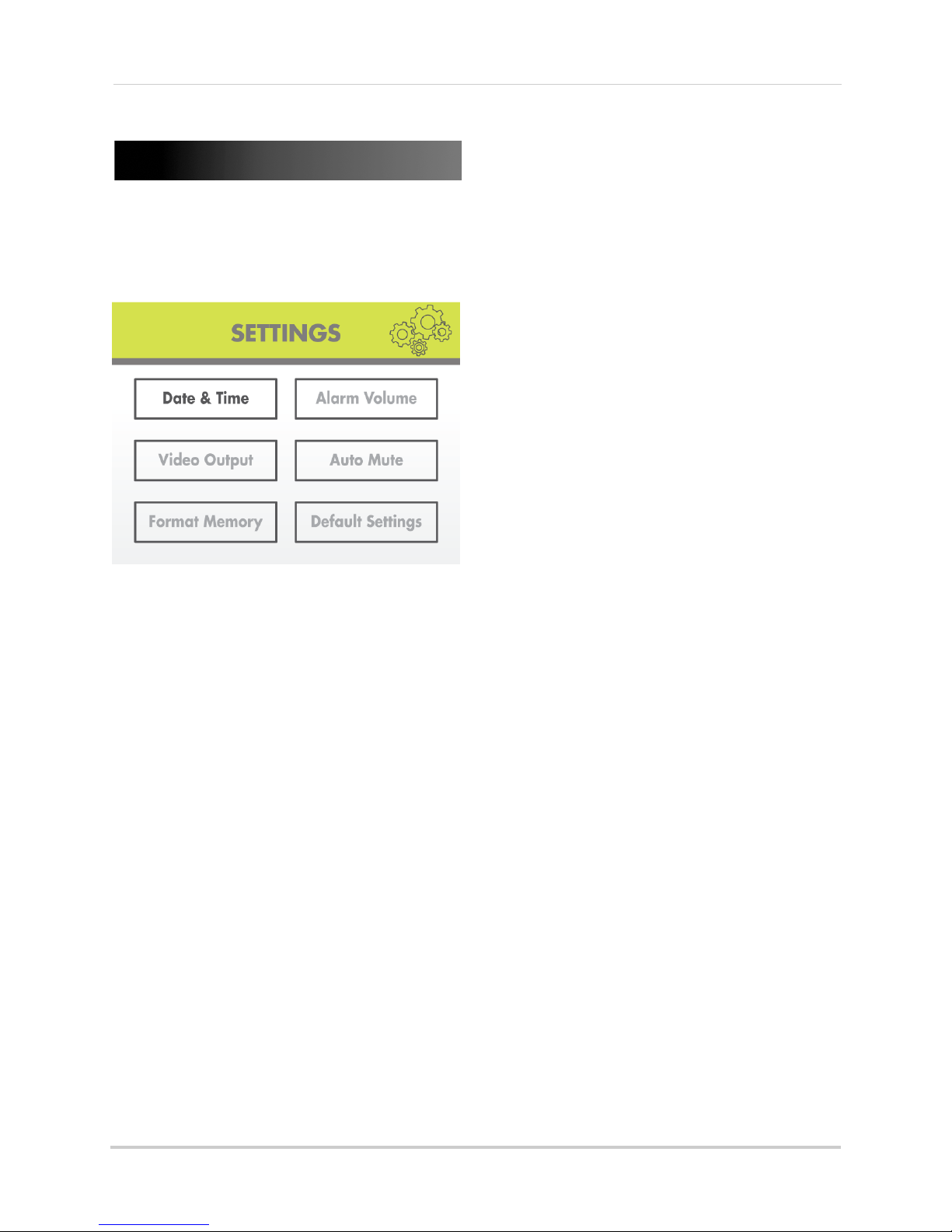
Settings
Settings
Use the Settings menu to set the system
time, change display options, and format
the SD card.
• If using AV out, changing the system alarm
volume will
output.
also affect the level of audio
To increase/decrease alarm
volume:
1 Press , then press RIGHT/LEFT to
The Settings menu contains the
following sub-menus:
• Date & Time: Set the date and time on the
system. For details, see “Setting the time”
on page 14.
• Alarm Volume: Increase/decrease the
alarm or button volume.
• Video Output: Select the TV system (NTSC/
PAL) for audio/video output.
• Auto Mute : Automatically mute audio from
the cameras when the level of sound
detected is low.
• Format Memory: Format the SD card.
• Default Settings: Restore the system to
factory settings.
Alarm Volume
Use the Alarm Volume menu to increase /
decrease the volume of the buzzer when
motion is detected by the camera(s). The
Alarm Volume also controls the volume of
the ’beep’ when you press buttons on the
wireless receiver. If you want to turn off the
buzzer or button sounds, turn the Alarm
Volume to the minimum setting.
select Settings and pr
2 Select Al
3 Press RIG
volume, and press LEFT to decrease the
alarm volume. Set the volume all the way
to the left to disable the alarm buzzer and
button sounds.
ess OK t
4 Pr
5 Press
arm Volume and press OK.
HT to increase the alarm
o save your settings.
until all menus are closed.
ess OK.
Video Output
Use the AV out menu to select the TV
system for the wireless receiver.
34
Page 47

Settings
Formatting erases all data on the SD card.
This step cannot be undone.
ATTE NTI ON
To select the TV system:
1 Press , then press RIGHT/LEFT to
select Settings and pr
2 From the Settings menu, select Vi
Output
3 Select
Europe) and press OK to save.
4 Press
and press OK.
NTSC (North America) or PAL (UK/
until all menus are closed.
ess OK.
deo
Auto Mute
The Auto Mute feature will automatically
mute audio from the cameras when the
level of sound detected is low. This is useful
if you wish to avoid playing white noise on
the receiver, but still want to hear audio if
something happens.
Format Memory
Use the Format Memory menu to format
the SD card. It is highly recommended to
format the SD card prior to initial
recording.
To format the SD card:
To enable Auto Mute:
1 Press , then press RIGHT/LEFT to
select Settings and pr
2 Select Auto
3 Select ON
changes.
4 Press
Mute and press OK.
and then press OK to save
until all menus are closed.
ess OK.
1 Insert the SD card into the SD card slot on
the wireless receiver until you hear a
"click." Please insert the card according to
the diagram on the panel.
ess
2 Pr
select Settings and pr
3 Select Fo
4 Select Ye
5 A message appears to confirm formatting.
ect Yes and press OK again to confirm.
Sel
Please allow a few moments for formatting
to finish. Formatti
depending on the size of the SD card.
, then press RIGHT/LEFT to
ess OK.
rmat Memory and press OK.
s and press OK.
ng time will vary
35
Page 48

Settings
Default Settings
Use the Default Settings menu to restore
the system to factory settings.
NOTE: Restore factory settings DOES
NOT delete video files on the SD
card, nor does it reset the date
and time on the system.
To restore default settings:
1 Press , then press RIGHT/LEFT to
select Settings and pr
2 Select De
3 Select
4 Press
fault Settings and press OK.
Yes and press OK.
until all menus are closed.
ess OK.
36
Page 49

Camera On/Off
Camera On/Off
Use the Camera On/Off menu to show/hide
camera channels on the main display
screen. For example, if you disable camera
3, it will not appear in any viewing mode.
To enable/disable cameras:
1 Press , then press RIGHT/LEFT to
select Camer
a ON/OFF and press OK.
Brightness
Use the Brightness menu to adjust the
brightness level of video coming from your
cameras.
NOTE: You cannot adjust the brightness
of the L
To adjust camera brightness:
1 While viewing, press UP/DOWN to select
the camera you would like to adjust.
CD display.
2 Press UP/D
camera and press RIGHT/LEFT to select
Active to show the camera or Skip to hide
it.
NOTE: The currentl
3 Press the OK
4 Press the
NOTE: Any disabled channels will be
OWN to select the desired
y selected camera
will have Active/Skip
highlighted in RED.
button to save changes.
button to exit.
ed out in Quad mode.
black
NOTE: You can set a separate
brightnes
camera.
2 Press
select Brightness and
3 Press RIG
level for the selected camera or LEFT to
decrease. Press OK to confirm.
ess the
4 Pr
5 Repeat st
cameras as needed.
HT to increase the brightness
eps 1~4 to configure your other
s level for each
, then press RIGHT/LEFT to
press OK.
button to exit.
37
Page 50
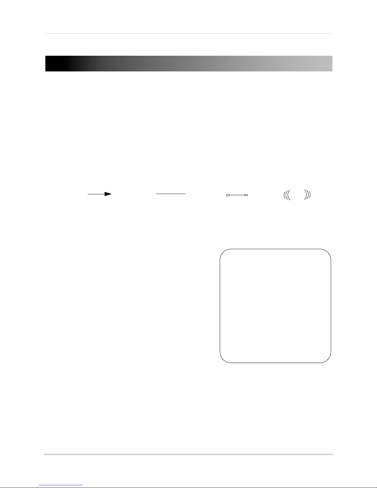
Viewing your camera remotely using Skype™
Skype server
Home computer
Disclaimers
You must have a high-speed
internet connection to use the
video function on Skype. Traffic
congestion may result in choppy
video.
Mobile Data Charges
When using a mobile cellular
network, data charges may apply.
Check with your provider for
details.
*Computer to computer
For Skype related support, visit
https://support.skype.com/
Viewing your camera remotely using Skype™
Connecting to your system through Skype is a convenient and free* method to view your
camera from anywhere with an Internet connection.
NOTE: When remotel
and recording are disabled.
y connecting to your video monitor using Skype, audio monitoring
How it works
Your computer connects to the Skype server. The Skype server is connected to your home
computer. Your home computer connects to the wireless receiver, which captures video from
the camera.
System requirements
For the latest device compatibility list, visit
www.lorextechnology.com
iPhone®, iPad®, iPod Touch® Requirements
•
Skype
for iPhone v. 3.0 and above.
Skype for iPad
•
• iPhone 5/4S/4/3GS, iPad (1st generation and above),
iPod touch (3rd generation and above).
• iOS 4.0 and above.
v. 3.5 and above.
.
Android Requirements
•
Skype
v. 2.8 and above.
• Android™ v. 2.3 and above.
PC requirements
• Skype for Windows v. 4.2 and above.
• Windows XP SP2/Windows Vista/Windows 7.
• 1 Ghz or greater processor.
For instructions, see “Connecting to Skype on a PC” on page 39.
Mac requirements
• Skype for Mac OS v. 5.3 and above.
• Mac
OS® v. 10.5.8 and above.
• 1 GHz or higher Intel processor (PowerPC™ not supported).
For instructions, see “Connecting to Skype on a Mac” on page 45.
38
Page 51

Viewing your camera remotely using Skype™
Run Lorex.exe
Click the USB Driver button
Then, click "USB Driver" to
copy the driver to your desktop.
Connecting to Skype on a PC
Step 1 of 6: Installing the camera driver for PC
You will need to install the camera drivers located on the software CD (included) or available
as a free download from www.lorextechnology.com.
To install the camera drivers:
1 Insert the software CD into your computer. An Autoplay window opens.
2 Click Run Lor
ex.exe.
3 Click the USB Driver button, and then click USB Driver for PC. The driver appears on your
desktop.
4 Click the button to close the window.
5 Double-click the Usbdr
iver-PC ( ) icon on your desktop.
6 Follow the on-screen instructions to complete the driver installation
39
Page 52

Viewing your camera remotely using Skype™
mini-USB cable
USB Port
Step 2 of 6: Connecting the video monitor to the PC
1 Turn on the camera first, then the video monitor. Make sure you can see a video image on
channel 1.
NOTE: Pair the camera that is most important for you to view remotely to Channel 1. For
ins
tructions on how to pair cameras, see “Pairing/adding cameras” on page 33.
2 Connect the mini-USB cable (included) to your video
The video monitor displays the following: "USB PC CAMERA MODE"
port.
monitor and into the computer’s USB
Step 3 of 6: Creating a Skype account
A Skype account allows you to connect to your camera through the Skype service. Skype is a
service that allows users to make voice calls and video calls to anywhere in the world.
In order to connect to your video monitor using Skype, you will need tw
camera (e.g Lorex Camera) and one for yourself (e.g. Tom Smith).
NOTE: The Skype illus
rations and instructions below serve as a guideline only. Skype may
t
change their website / product interface without prior notice.
o accounts—one for the
If you do not have a Skype account
See “If you do not have a Skype account...” on page 50.
If you have an existing Skype account (PC)
You will have to create a separate account for your camera. Follow the instructions below.
1 Launch Skype. If y
40
ou are connected to Skype, click Skype>Sign Out.
Page 53

Viewing your camera remotely using Skype™
Click Create a new account
Live video
Continue
Selec t Wireless Mo nitoring
System if necessary
Live video
Save button
Video Settings
Select Wireless Monitoring System
if necessary
2 From the Skype Login window, click Create a new account.
3 Follow the on-screen instructions to create a new account. Upon login, the Setting up Skype
wizard starts. Click Continue. Under Video, you will see an image from the camera. If no
image appears, make sure the monitor is connected to the computer via the USB cable.
NOTE: If you can see an image from a webcam that is already connected, select Wireless
Monitoring System from the drop-down menu.
d
NOTE: If the Setting up Skype wizar
does not run, click Tools>Options>Video Settings.
Make sure you can see video in the window. Click Save to exit. If the image is from
an already connected webcam, select Wireless Monitoring System under Select
Webcam.
41
Page 54

Viewing your camera remotely using Skype™
Options
Show advanced options
4 Click Continue.
5 In the next page, click Add later t
o not include a profile picture for the camera’s Skype
account, or click Continue and follow the instructions to add a profile picture for the camera’s
Skype account.
ick Start using Skype.
6 Cl
Step 4 of 6: Configuring Skype
7 Click on Tools>Options.
8 Click the Calls button ( ).
9 Click the Show advanced options but
ton.
10 Under Allow calls from..., select people in my Contact list only. This will prevent the device
from accepting Skype calls from anyone who is not in the contact list for its account.
NOTE: You may also select anyone, which will allow anyone with a Skype account to call
the device and access your camera. This setting is not recommended
42
Page 55

Viewing your camera remotely using Skype™
Save
Add a contact
Search for the name of your
personal Skype account
Click Add
11 Check Answer incoming calls automatically and Start my video automatically when I am in
a call.
Click Save.
Step 5 of 6: Send a contact request
Next, you have to send a friend request to your personal account (e.g. Tom Smith).
1 Click the A
dd a contact button ( ).
2 Search for the name of your personal account (e.g. Tom Smith), and then click the Add button.
43
Page 56

Viewing your camera remotely using Skype™
Send contact request
3 Click Send Request.
Step 6 of 6: Test the connection
NOTE: This step requires you to log in to Skype from a different computer or compatible
mobile device.
1 Log in to your personal account (e.g. Tom Smith).
2 A "new contact" pop-up appears. Click the new contact request icon that appears on the
bottom-right c
orner of the window.
3 Click the Add to Contacts button to add the camera to your contact list.
44
Page 57

Viewing your camera remotely using Skype™
Call
4 From the contact list, right-click on your camera’s account name (e.g. Lorex Camera), and
click Call. The video call begins automatically. Please allow around 15 to 25 seconds for the
video connection to be established.
NOTE: Video may appear pixelated immediately after connecting. It should improve within
a few seconds, depending on your Internet connection.
Connecting to Skype on a Mac
Step 1 of 6: Installing the camera driver for Mac OS
You will need to install the camera drivers included on the software CD (included) or available
as a free download from www.lorextechnology.com.
1 Insert the software
2 Double-click the Lor
3 Double-click the Mac fo
4 Double-click the SD Series Mac Driv
your Downloads folder and your downloads folder opens automatically.
5 Doubl
6 Follow the on-screen instructions to install.
e-click the SD S
WirelessCameraMacDriverSuiteInstaller (.pkg) file.
CD into your computer. The Lorex CD icon ( ) appears on your desktop.
ex CD icon ( ) on your desktop.
lder.
er.zip file to extract the installer. The installer is saved to
eries Mac Driver folder and then double-click the
Step 2 of 6: Connecting the video monitor or receiver to your computer
1 Turn on your camera first, and then turn on your video monitor or receiver. Make sure you can
see a video image on Channel 1.
NOTE: Pair the camera that is most important for you to view remotely to Channel 1. For
ins
tructions on how to pair cameras, see “Pairing/adding cameras” on page 33.
45
Page 58

Viewing your camera remotely using Skype™
mini-USB cable
USB port
Create New
Account
2 Connect the mini-USB cable (included) from the USB port on your video monitor or receiver
to an available USB port on your computer. "USB PC CAMERA MODE" appears on the screen.
Step 3 of 6: Creating a Skype account
A Skype account allows you to connect to your camera through the Skype service. Skype is a
service that allows users to make voice and video calls to anywhere in the world.
In order to connect to your video monitor using Skype, you will need two accoun
camera (e.g. Lorex Camera) and one for yourself (e.g. Tom Smith).
ts—one for the
NOTE: The Skype illust
rations and instructions below serve as a guideline only. Skype may
change their website / product interface without prior notice.
If you do not have an existing Skype account:
See “If you do not have a Skype account...” on page 50.
If you have an existing Skype account (Mac):
You have to create a separate account for your camera. Follow the instructions below.
1 Launch Skype. If
2 Click Cr
eate New Account.
you are already connected to Skype, click File>Sign Out.
3 Follow the on-screen instructions to create a new account.
46
Page 59

Viewing your camera remotely using Skype™
Audio/Video tab
Calls tab
Answer
automatically
Click Configure
Step 4 of 6: Configuring Skype
1 Upon login, click Skype>Preferences. Select the Audio/Video tab.
2 Under Camera, select Wireless Monitoring System if it is not already selected. You will see
live video from your camera if your device is connected.
• If the video area is black, check to see if your ca
mera is on and is paired to Channel 1. Also
check to make sure your video monitor is connected to your computer.
NOTE: When c
nnecting or reconnecting your video monitor, you must close the
o
Preferences window and re-open it to the Audio/Video tab to test the video
connection.
lect the Calls ta
3 Se
b.
4 Under Incoming Calls, select Answer Automatically.
5 Click Configur
e.
47
Page 60

Viewing your camera remotely using Skype™
Select Answer automatically with video
Allow calls
from Contacts
Privacy tab
Add Contact
6 Select Answer automatically with video. Click Done.
7 Select the Privacy tab.
8 Under Allow calls from, select Co
ntacts. This will prevent the device from accepting Skype
calls from anyone who is not in the contact list for its account.
NOTE: You may also select Anyone, which will allow anyone with a Skype account to call
the device and access your camera. This setting is not recommended.
9 Close the Preferences window to return to the main Skype window.
Step 5 of 6: Send a contact request
Next, you have to send a friend request to your personal Skype account (e.g. Tom Smith).
1 From the main Skype window, click Co
ntacts then click Add Contact.
48
Page 61

Viewing your camera remotely using Skype™
Enter the account name or
email address for your
personal Skype account
Click Find
Send contact request
Contact
Request
Accept
Call
2 Under Add Contact, enter the Skype account name (e.g. Tom Smith) or email address for your
personal Skype account. Click Find. Your personal Skype account should appear below the
search bar.
3 Next to your personal Skype account, click and then click Send to send the contact
request.
Step 6 of 6: Test the connection
NOTE: This step requires you to log in to Skype from a different computer or compatible
mobile device.
1 Log in to your personal account (e.g. Tom Smith).
2 The contact request from your device’s Skype account should appear in the left column under
ent. Click the Skype account name for your device.
Rec
3 Click Accept.
4 Click the
(Make a Voice Call) button to call your camera. The video call begins
automatically. Please allow around 15 to 25 seconds for the video connection to be
ablished.
est
• You can also call the camera from the contact list using the button. Do not use
the Video Call (
NOTE: Video may appear pixelated immediately after c
) button.
onnecting. It should improve within
a few seconds, depending on your Internet connection.
49
Page 62

Viewing your camera remotely using Skype™
Join Skype
Create Account
I Agree - Continue
If you do not have a Skype account...
Create your personal account first (e.g. Tom Smith), then create a second account for your
camera (e.g. Lorex Camera).
Create a personal account (i.e. Tom Smith):
1 Go to www.skype.com, and click on Join Skype.
2 Click Create an Account. Fill in the appropriate fields.
3 Click the I Agree - Continue button.
4 Follow the on-screen instructions to download and install Skype on your computer.
5 Once you are logged in to Skype, click on Skype>Sign out (PC) or File>Sign out (Mac), t
see “If you have an existing Skype acc
Skype account (Mac):” on page 46.
50
ount (PC)” on page 40 or see “If you have an existing
hen
Page 63

"Personal" Skype account
(e.g. Tom Smith)
"Camera" Skype account
(e.g. Lorex Camera)
Skype Name:
Password:
Email address used to register this
account (used for account retrieval):
Skype Name:
Password:
Email address used to register this
account (used for account retrieval):
My Skype Account Information
cam 1
USB PC CAMERA MODE
Press UP/DOWN to change the channel that
will be shown through Skype
Changing the camera view on Skype
Viewing your camera remotely using Skype™
NOTE: This section is applicable only if you have more than 1 camera.
You cannot change the camera remotely using Skype; however, you can change the camera
that is shown
Pair the camera that is most important for you to view remotely to Channel 1. When you
connect the USB cable to the
you have a different channel selected.
To change the camera view:
1 With the wireless receiver connected to your computer using a USB cable, press UP/DOWN to
change the channel that is shown when a remote user connects through Skype.
NOTE: You can only view one camera at a time.
on Skype manually using the video monitor.
video monitor, the video monitor defaults to Camera 1, even if
51
Page 64

Viewing your camera remotely using Skype™
Voice Call button
Viewing a camera on your smart phone or tablet
You can remotely monitor your camera using Skype on supported smart phones or tablets.
Supported apps & devices
For the latest device compatibility list, visit www.lorextechnology.com.
iPhone / iPad / iPod touch
•
Skype
for iPhone v. 3.0 and above
•
Skype for iPad
• iPhone 5/4S/4/3GS, iPad (1st generation and above), iPod touch (3rd generation and above)
• iOS 4.0 and above
Android
•
Skype
v. 2.8 and above
• Android v. 2.3 and above
Prerequisites
• Install and configure the PC/Mac Skype software and USB drivers. For details, see “Viewing
your camera remotely using Skype™” on page 38.
• Ensure the video monitor is connected to your computer with the USB cable.
• Ensure you have configured your camera’s Skype account to auto-accept incoming calls.
• Ensure your personal Skype account has been added to the contact list for the video monitor’s
Skype account.
v. 3.5 and above
Viewing your camera on iPhone
1 Download and install the
NOTE: Skype is a fr
2 Launch Skype
Contacts. If a different contact list is open, tap Contacts and then tap All Contacts.
3 Select the video monitor’s account, and tap
Vo
ice Call to connect to the camera. The
video call connects automatically. Please
allow 15 to 25 seconds for the call to
connect.
NOTE: Video may appear pixelated
immediately after connecting. It
should improve within a few seconds,
depending on your Internet
connection.
ee application, but it requires a valid iTunes account to download.
and sign in using your personal account. Your contact list opens to All
Skype
application from the App Store.
52
Page 65

Viewing your camera on iPad
Voice Call button
Voice call button
1 Download and install the
Skype for iPad
Viewing your camera remotely using Skype™
application from the App Store.
NOTE: Skype fo
2 Launch Skype
Contacts. If a different contact list is open, tap Lists (
r iPad is a free application, but it requires a valid iTunes account to download.
and sign in using your personal account. Your contact list opens to All
) and then tap All Contacts.
3 Select the video monitor’s
count, and tap Voice Call to
ac
connect to the camera. The
video call connects
automatically. Please allow 15
to 25 seconds for the call to
connect.
NOTE: Video may appear
pixelated immediately
after connecting. It
should improve within a
few seconds, depending
on your Internet
connection.
Viewing your camera on an Android smartphone or tablet
1 Download and install the
NOTE: Skype is a fr
ee application.
Skype
application from the Google Play Store.
2 Launch Skype
3 Tap Co
ntacts.
and sign using your personal account.
4 Tap the name of the video monitor’s
count, and tap Voice Call to connect
ac
to the camera. The video call connects
automatically. Please allow 15 to 25
seconds for the call to connect.
NOTE: Video may appear pixelated
immediately after connecting. It
should improve within a few
seconds, depending on your
Internet connection.
53
Page 66

Technical specifications
Technical specifications
General
Description Specification
Transmission Frequency 2,400~2,483.5MHz
Transmission Power 16dBm
Unobstructed Effective
Range
Spread Spectrum FHSS
Modulation Mode GFSK
Operating Temperature 14 ~ 122° Fahrenheit / -10 ~ +50° Celsius
Operating Humidity < 85
Camera
650ft / 200m (line of sight)
%
Description Specification
Image Sensor 1/4" CMOS Image Sensor
Resolution 640 x 480pxl (NTSC)
Minimum Illumination 0Lux (IR on)
Night Vision Distance 40ft (12m)
PIR Range 21ft (6.5m)
View Angle Diagonal 52°
Power Consumption (Max.) Max 460mA
Power Supply 9V DC
Dimensions W: 75mm, L: 110mm, H: 190mm
Weight 0.60lbs / 0.27kg
LCD receiver
Description Specification
Display 9" diagonal or 7" diagonal (check package for display size)
LCD Resolution 800x480
Receiving Sensitivity -81dBm
Power Consumption (Max.) 7" Model: 950mA
9" Model: 1050mA
Power Supply 5V DC
Dimensions 7" Model: W: 42mm, L: 201mm, H: 150mm
9" Model: W: 42mm, L: 254mm, H: 202mm
Weight 7" Model: 1.55lbs / 0.70kg
9" Model: 1.00lbs / 0.44kg
54
Page 67

Strengthening the range of the wireless signal
Clear line of sight
Clear line of sight
Cable accessory antenna
Strengthening the range of the wireless signal
DISCLAIMER: Certain accessories are not available in all markets.
There are several ways to boost your wireless signal as well as options to help you extend the
range of the wireless signal.
Clear line-of-sight
The digital wireless signal is virtually interference free. However, you should always ensure
there is a clear line-of-sight between the camera and the receiver.
Obstacles
There should be little to no obstacles obstructing the line-of-sight between the camera and
the receiver. Solid objects, such as concrete and metal may limit the range of the wireless
signal.
Extending your wireless signal
Even with a clear line-of-sight between your camera(s) and your receiver, you may experience
a lower video frame rate simply due to the distance between your wireless devices.
Accessory antennas are available that can help extend the range of your wireless
signal.
55
Page 68

Strengthening the range of the wireless signal
Directional Wireless Panel Antenna
2.4 GHZ Directional Wireless Panel Antenna
Use the 2.4GHz Directional Wireless Panel Antenna (model #:
ACCANTD9) to focus a
camera in order to increase range of transmission (clear
line
-of-sight between the camera and the antenna is
required). A 20ft extension cable is included help with proper
position of the antenna.
wireless signal onto one specific
2.4 GHZ Omni-Directional Wireless Antenna
Use the 2.4GHz Omni-Directional Wireless Antenna (model #: ACCANTO8) to extend the range
and boost the signal of several wireless cameras. You should position the Omni-Directional
Wireless Antenna in an elevated position to provide a clear line-of-sight to the cameras. A 20ft
extension cable is included help with proper position of the antenna.
Visit www.lorextechnology.com for more details on wireless antennas and accessories.
56
Page 69

Power failure indicator
Power Failure icon
Power failure indicator
A power failure may interrupt recording modes on the system. After power is restored, the
following will occur:
• The system will restart in Auto Sequenc
form of recording will be immediately active on the system.
e mode + Motion Recording - this ensures that some
NOTE: If y
• A Power Failure icon ( ) appears on-screen. The Power Failure icon indicates that a power
ailure occurred while the system was actively recording (i.e. "REC" icon was on-screen).
f
NOTE: The ic
ou had a different display view or recording mode set when the power failure
occurred, you will need to re-apply the previous display view and recording mode.
on appears only if the system was actively recording when the power failure
occurred. The icon will disappear when you press buttons on the receiver.
NOTE: Video fil
recording, recordings from up to 10 minutes before the power failure occurred will
not be saved.
es are saved every 10 minutes of recording. If a power failure occurs during
57
Page 70
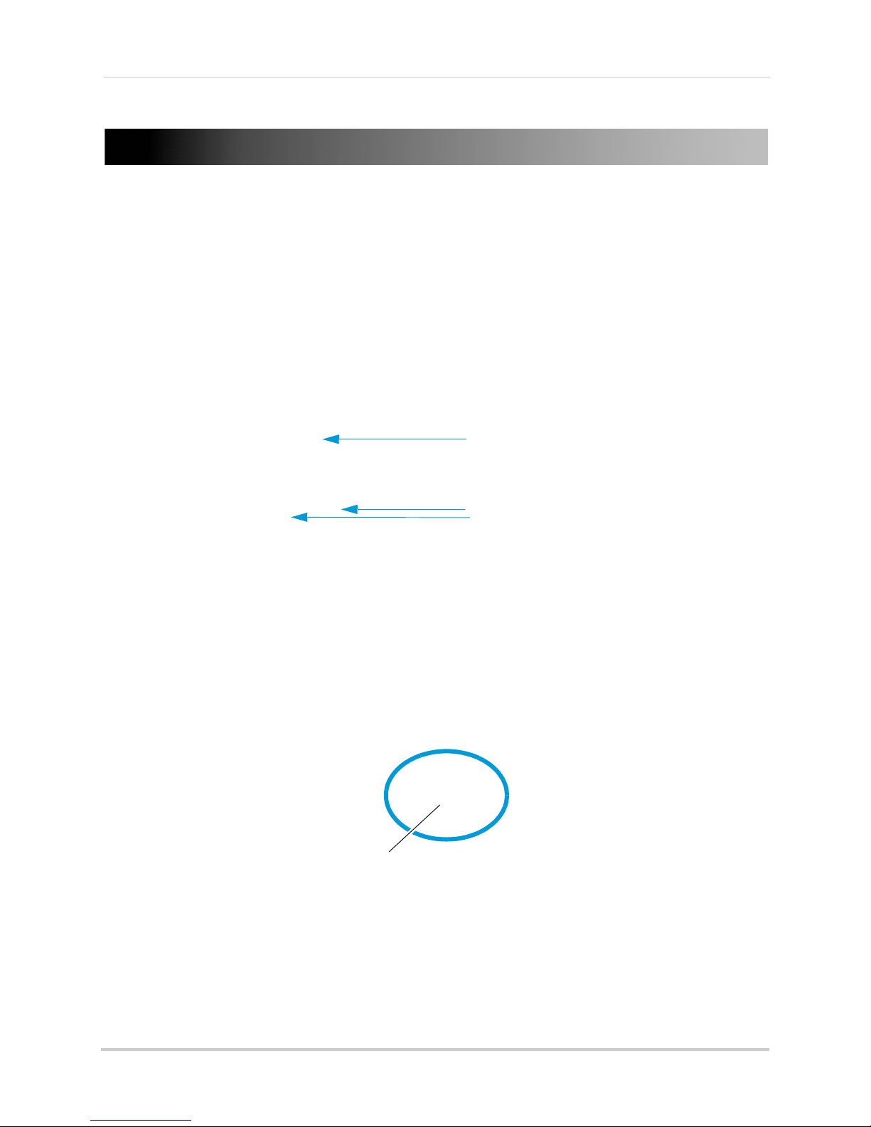
Mounting the LCD receiver
Thumbscrew
Mounting the LCD receiver
The LCD Receiver can mounted to a wall or underneath a counter or cupboard.
To mount the LCD receiver:
1 Select a location to mount the receiver. The location should have a clear reception to your
camera(s). Place the mounting stand in the desired mounting position and mark holes for the
screws.
NOTE: A
2 Drill the hol
Make sure all three screws are fastened tightly at the connection points.
3 Adjust the antenna on the LCD receiver to allow for proper clearance with your mounting
surface.
4 Attach
then
void installing in a location which requires the wireless signal to pass through
c
ement, concrete, and metal structures. This will reduce the range of transmission.
es, and then mount the stand to the desired surface using the provided screws.
the LCD receiver to the mounting stand. Adjust the position of the LCD receiver, and
tighten the thumbscrews to secure.
58
Page 71

Troubleshooting
Problem Solution
Troubleshooting
There is no picture from a
Camera
The picture is dropping
The Picture is or has become
choppy
The Pi
Bright spot in image while
view
The Picture appears to be
grainy/dis
Cannot access the menu
cture is white
ing camera at night
torted
•
Check power to the camera
e sure that the cameras and receiver are both ON
• Mak
• Make sure that the camera is in range of the receiver
• Move the camera closer to the receiver
• Tr
y repositioning the camera, receiver or both to improve
the reception
• The picture may become choppy when experiencing a lower
frame r
second vs. a higher 20 frames per second)
• Try moving the camera closer to the receiver
• Remove obstructions between the receiver and camera
• Consider increasing the range of the wireless signal with an
accessory antenna (see page 55 for details)
• Common situation know as "washout" or "whitewash"
where a s
The camera lens IS NOT harmed during a whitewash
• DO NOT point your camera towards a light source
• This occurs when a camera is pointed at a window to see
outside, bec
light that reflects off the glass. If you need to look outside,
install the camera outdoors. Please note that the camera
must be installed under shelter when placed outdoors
• When using with large screen TV/monitor (especially
high-def
the camera limits video resolution to VGA (640x480 pixels).
This is not a product defect
• For best performance use with TV/monitor PIP (Picture in
Picture) function. Check your TV/monitor product manual to
see if this feature is available on your TV/monitor
• Use with a smaller TV/monitor
• You cannot access the menu while recording is on:
ate due to reduced signal strength (i.e. 10 frames per
trong light source is pointed at the camera lens.
ause the night vision LED's produce Infrared
inition televisions), the picture might be grainy as
"Err" appears on the
on-screen display
• Pres
• Press to disable motion recording
• The system has encountered an error with the SD card.
• If "Err" still appears on the OSD, format the SD card
s to disable manual or scheduled recording
Po
wer off the receiver, remove then re-insert the SD card,
and then power the receiver back on
59
Page 72

Frequently asked questions
Frequently asked questions
Q: How do I install USB drivers for remote viewing using Skype™?
A: USB drivers for Skype™ remote viewing on PC and Mac are available on the CD or as a free
download from www.lorextechnology.com.
To install USB Driver for Windows:
• Install the Driver for PC from the CD.
OR
• Go to www
your model. Extract the installer file, double-click USBdriver.exe, and follow the on-screen
instructions to install.
To install USB Driver for Mac:
• Install the SD Series Mac Driver file located in the Mac folder on the CD.
OR
• Go to www
your model. Double-click the .zip file to extract the contents. Open the folder SD Series Mac
Driver and double-click the WirelessCameraMacDriverSuiteInstaller (.pkg) file. Follow the
on-screen instructions to install.
.lorextechnology.com and download USB PC Driver from the Downloads tab for
.lorextechnology.com and download USB Mac Driver from the Downloads tab for
Q: How do I setup remote viewing using Skype™?
A: Follow the instructions under “Viewing your camera remotely using Skype™” on page 38. If
you have followed the instructions and still can't connect, ch
• Have you installed USB drivers for the video monitor? See question above for details.
• Is the
USB PC CAMERA MODE on the screen when it is connected. The video monitor must be
connected via the USB cable to access the video over Skype.
• Have you created a separate Skype account for the wireless receiver? You must create a
separate account for the video monitor so you can call it using your personal Skype account.
• Have you added your personal Skype account to the Contacts list for the video monitor's Skype
account?
• Have you enabled the video monitor Skype account to auto-answer incoming calls? For PC
instructions, see “Step 4 of 6: Configuring Skype” on page 42. For Mac instructions, see “Step
4 of 6: Configuring Skype” on page 47.
video monitor connected to your computer using a USB cable? The monitor will say
eck the following:
60
Page 73

Frequently asked questions
Video Settings
Select Wireless
Monitoring System
Q: My computer already has a webcam. How do I get Skype™ to use the
video monitor instead?
A: Follow the steps below to change the primary camera in Skype to the video monitor.
To change the primary camera to the video monitor in Skype on PC:
1 Click Tools>Options.
2 Click the Video Settings butt
3 Under Sel
ect Webcam, select Wireless Monitoring System to make the video monitor the
primary camera.
on.
4 Click Save.
NOTE: You will have to reselect your webcam under Select webcam to use it for regular
Skype video c
alls.
To change the primary camera to the video monitor in Skype on Mac:
1 Click Skype>Preferences.
2 Select the Audio/Video ta
b.
61
Page 74

Frequently asked questions
Audio/Video tab
Select Wireless
Monitoring System
3 Under Camera, select Wireless Monitoring System.
4 Close the Preferences window to return to the main Skype window.
NOTE: You will have to reselect your webcam under Camera to use it for regular Skype
video c
alls.
Q: How do I change the camera that is shown through Skype™?
A: Viewing through Skype does not allow you to change channels remotely; however, you can
manually change the channel that is shown on Skype.
To change the channel that is shown on Skype:
With the wireless receiver connected to the computer using a USB cable, press UP/DOWN to
change the channel number. The camera number changes from "cam 1" to "cam 2".
Q: Can I extend the wireless range of the receiver?
A: Yes. There are optional antennas available at www.lorextechnology.com that help boost
wireless signals.
Q: What is the maximum distance I can have between the camera and the
receiver?
A: Typically 650 feet (200m) with a clear line of sight in open space, or approximately 180 feet
(55m) in a house. Walls, studs, furniture will interfere with the range of wireless transmission.
Try repositioning the camera and/or monitor to achieve optimal signal strength.
Q: Is the signal secure?
A: Yes. The Digital Wireless signal transmission type used by the receiver is also known as
FHSS- Frequency Hopping Spread Spectrum. This type of signal is highly resistant to
deliberate jamming as it generates a channel hopping sequence using a sophisticated
algorithm generated by the receiver system.
62
Page 75

Page 76

LW2730/LW2930 Series
Version 1.0
www.lorextechnology.com
Copyright © 2012 Lorex Technology Inc.
 Loading...