

Page 1
MODEL:
VS6428
Copyright © 2007 Lorex Technology Inc.
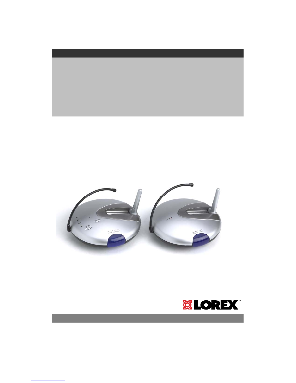
2.4 GHZ WIRELESS
VIDEO SENDER
Instruction Manual
English Version1.0
www.lorexcctv.com
Page 2
CAUTION
RISK OF ELECTRIC SHOCK. DO NOT OPEN.
CAUTION: TO REDUCE THE RISK OF ELECTRIC SHOCK, DO NOT REMOVE
COVER (OR BACK). NO USER-SERVICEABLE PARTS INSIDE. REFER
Explanation of two Symbols
!
THE GRAPHIC SYMBOLS WITH SUPPLEMENTAL MARKING ARE ON
THE BOTTOM OF THE SYSTEM.
WARNING: To prevent fire or shock hazard, do not expose this unit to
FCC CLASS B NOTICE
SERVICING TO QUALIFIED SERVICE PERSONNEL.
The lightning flash with arrowhead symbol, within an
equilateral triangle, is intended to alert the user to the
presence of uninsulated "dangerous voltage“ within the
product's enclosure that may be of sufficient magnitude to
constitute a risk of electric shock to persons.
The exclamation point within an equilateral triangle is
intended to alert the user to the presence of important
operating and maintenance(servicing) instructions in
the literature accompanying the appliance.
rain, water, or wet locations. Do not insert any metallic object
through the ventilation grills.
!
Note:
This equipment has been tested and found to comply with the limits For a Class
B digital device, pursuant to Part 15 of the FCC Rules. These limits are
designed to provide reasonable protection against harmful interf erence in a
residential installation. This equipment generates, uses and can radiate radio
frequency energy and, if not installed and used in accordance with the
instruction, may cause harmful interference to radio communicati ons.
However, there is no guarantee that interference will not occur in a particular
installation. If this equipment does cause harmful interference to radio or
television reception, (which can be determined by turning the equipment off
and on), the user is encouraged to try to correct the interference by one or more
of the following measures:
• Reorient or relocate the receiving antenna
• Connect the equipment into an outlet on a circuit different from that to which
other devices may be connected.
• Consult the dealer or an experienced radio or television technician for help.
• Complies with Industry Canada 210
i
Page 3

SAFETY INSTRUCTIONS
IMPORTANT SAFEGUARDS
All the safety and operating instructions should be read before the
system is operated, and retained for future reference.
1. HEED WARNINGS - All warnings on the appliance and in the operating
instructions should be adhered to.
2. FOLLOW INSTRUCTIONS - All operating instructions should be
followed.
3. WATER AND MOISTURE - Do not use this video product near water –
for example, a bath tub, wash bowl, kitchen sink, laundry tub or
swimming pool, or in a wet basement.
4. POWER SOURCES - This product should be operated only from the type
of power source indicated on the marking label.
5. OVERLOADING - Do not overload outlets and extension cords, which
can result in a risk of fire or electric shock.
6. SERVICING - Do not attempt to service this product yourself. Opening or
removing covers may expose you to dangerous voltage or other hazards.
Refer all servicing or repairs to qualified service personnel.
7. DAMAGE REQUIRING SERVICE - Unplug this product from the wall
outlet and refer servicing or repairs to qualified service personnel under
the following conditions:
a. When the power supply cord or plug is damaged.
b. If liquid has been spilled or objects have fallen into the product.
c. If the product has been exposed to rain or water.
d. If the product does not operate normally by following the operating
instructions. Adjust only those controls that are covered by the
operating instructions.
e. If the product has been dropped or the cabinet has been damaged.
f. When the product exhibits a distinct change in performanc e.
8. REPLACEMENT PARTS - When replacement parts are required, be
sure the service technician has used replacement parts that are
specified by the manufacturer or have the same characteristics as the
original part. Unauthorized substitutions may result in fire, electric
shock, or other hazards.
9. SAFETY CHECK - Upon completion of any service or repairs to this
video product, ask the service technician to perform safety checks to
determine if the video product is in proper operating condition.
10. An appliance and cart combination should be moved with care.
Do not place this equipment on an unstable cart, stand, or table.The
equipment may fall, causing serious injury to a child or adult, and
serious damage to the equipment. Wall or shelf mounting sho uld
follow the manufacturer's instructions and should be done with
a mounting kit approved by the manufacturer.
ii
Page 4

TABLE OF CONTENTS PAGE
INTRODUCTION & FEATURES………………………………………
SYSTEM INCLUDES…………………………………………………..
CONTROLS AND FUNCTIONS
Wireless Transmitter…................….……………………..……...
Wireless Receiver...……..............................……….……...……
INSTALLATION OF WIRELESS TRANSMITTER………………….
INSTALLATION OF WIRELESS RECEIVER
Operation with TV (Using RCA Cables)......……………….…....
Operation with TV (Using Coaxial Cable) ..............…..……......
Operation with TV and VCR………………………………………
SYSTEM OPERATION
Multiple Devices / Manual Options ………………………………
TROUBLE SHOOTING ..............................................………..…...
TECHNICAL SPECIFICATIONS ....................................................
CARE & MAINTENANCE ……………………………..……………….
1
2
3
4
5
6
7
8
9
10
11
12
iii
Page 5
INTRODUCTION:
Thank you for purchasing the 2.4 GHz 4 Channel Wireless Video
Sender. This system easily connects to any TV, allowing you to view
your satellite, DVD or security Camera from another room, up to a
distance of 300 ft away (open space). Avoiding the hassle of running
wires, this system is easy to install and operate for immediate
applications.
The RCA audio/video outputs also allow you to connect a time lapse
VCR or standard VCR for recording purposes.
To learn more about this 2.4GHz Wireless Video Sender and our
complete range of CCTV products, please visit our website at:
www.lorexcctv.com
FEATURES:
• Send signal to a second TV Satellite, DVD, or Security Camera
• View video from another room
• 300 ft Wireless Transmission (open space)
• 2.4 GHz Wireless Transmission
• Crystal clear Video and Stereo audio
• 4 Channel Wireless System
1
Page 6
SYSTEM INCLUDES:
1 - 2.4 GHz Wireless Receiver
1 - 2.4 GHz Wireless Transmitter
Also includes:
2 – 9V DC 500mA Adapters
2 – RCA Audio/Video Cables
1 – Coaxial Cable
Owner’s Manual
2
Page 7

CONTROLS & FUNCTIONS
WIRELESS TRANSMITTER
TOP VIEW
REAR VIEW
2
3
4
5
6
1
7
BOTTOM VIEW
Location of Transmitter controls
1. Channel Selector Button – Used to select between channels 1-4
2. LED Channel Indicators – Indicator light shows selected channel
3. 2.4 GHz Antenna – High gain dipole antenna transmits audio and video
signal to the wireless receiver
4. DC IN Jack – Power source for the transmitter
5. Video Input Jack (Yellow) – RCA jack for video input connector
6. Audio Input Jacks L (White) & R (Red) – RCA jacks for audio input
connector
7. ON/OFF Power Switch – Ensure this switch is set to OFF before
plugging the system into an electrical outlet
.
.
3
Page 8

WIRELESS RECEIVER
CONTROLS & FUNCTIONS
2
1
8
TOP VIEW
3
9
BOTTOM VIEW
REAR VIEW
4 5 6 7
Location of Receiver controls
1. Channel Selector Button – Used to manually switch channels from 1-4
2. LED Channel Indicators – Indicator light shows selected channel
3. 2.4 GHz Antenna – High gain dipole antenna receives audio and video
signal from the wireless transmitter
4. Video Output Jack (Yellow) – RCA jack for video output connector
(when using RCA connector)
5. Audio Output Jacks L (White) & R (Red) – RCA jacks for audio
output connector (when using RCA connector)
6. RF Out Jack (To TV) – Connect the receiver to a TV using the supplied
coaxial cable. (alternative to RCA cable connection)
7. DC IN Jack – Power source for the receiver
8. ON/OFF Power Switch – Ensure this switch is set to OFF before
plugging the system into an electrical outlet
9. Channel 3/4 Selector Switch – Used to view picture on television when
using coaxial cable (preset to channel 3)
4
Page 9

INSTALLATION OF TRANSMITTER
CONNECTING A TRANSMITTER SIGNAL FROM YOUR VCR/
SATELLITE/DVD
STEP 1:
Back of Transmitter
Electrical
Outlet
RCA Cable (Supplied)
Rear of
VCR
NOTE
Ensure the Power Switch on the Transmitter is turned OFF prior to
proceeding with the following steps.
1. Connect one end of the RCA cables to the Audio/Video Input jacks of the
Transmitter; the other end to the Audio/Video Out jacks of the
VCR/Satellite/DVD. Ensure that the yellow, red and white plu gs match the
yellow, red and white jacks on both the VCR/Satellite/DVD and the
Transmitter.
2. Plug one end of the supplied power adapter (9V 500 mA adapter) into the
back of the transmitter; the other end into an electrical outlet. The system is
defaulted to channel 1.
5
Page 10

INSTALLATION OF RECEIVER
CONNECTING A RECEIVER TO A REMOTE TV USING RCA CABLES
STEP 2:
You have two options to connect the Receiver: A) Using RCA Cables
(see below), or B) Coaxial Cables, please refer to page 7 of this manual.
A)
NOTE
1. Place the wireless receiver near your television (or monitor).
2. Connect one end of the RCA cables to the Audio/Video output jacks at the
back of the Receiver. Plug the other end of RCA cables into the
Audio/Video In jacks on your television. Be sure the yellow, red and white
plugs match the yellow, red and white jacks on both the receiver and TV.
3. Connect one end of the supplied 9V 500 mA AC adapter into the DC IN
jack at the rear of the receiver; the other end into an elec trical outlet. Turn
the receiver ON. The system is defaulted to channel 1.
Back of Receiver
Electrical Outlet
Ensure the Power Switch on the Receiver is turned OFF before
proceeding with the following steps.
Television
4. Turn your T.V. to AX (Aux. Mode or TV/Video) to view the picture on your
second T.V.
5. Adjust the antenna on both the transmitter and receiver as necessary for
optimum viewing.
NOTE
For optimum viewing reception you may need to change the
channels of both your transmitter and receiver to the same
channels between CH 1 – CH 4
6
Page 11

INSTALLATION OF RECEIVER
CONNECTING A RECEIVER TO A T.V. USING COAXIAL CABLES
B)
Television
Back of Receiver
Electrical Outlet
Audio Video
Coaxial Cable (75 ohm)
NOTE
1. Place the wireless receiver near your television (or monitor).
2. Connect one end of the coaxial cable to the back of the Recei ver. Plug the
3. Connect one end of the supplied 9V 500 mA AC adapter into the DC IN jack
Ensure the Power Switch on the Receiver is turned OFF prior to
proceeding with the following steps.
other end of the coaxial cable to the television.
at the back of the receiver; the other end into an electrical outlet. Turn the
receiver ON. The system is defaulted to channel 1.
4. Search channels 1 through 4 by using Channel Selector Switch on the
Receiver and Transmitter.
5. Turn your T.V. to channel 3 to view the picture from your sec ond T.V.
6. Adjust the antenna on both the transmitter and receiver as necessary for
optimum viewing.
For optimum viewing reception you may need to change the
NOTE
channels of your transmitter and receiver to the same channels
between CH1 – CH 4
7
Page 12

INSTALLATION OF RECEIVER
CONNECTING A RECEIVER TO A REMOTE TV THROUGH A VCR
RCA Cable (Supplied)
Rear of
Back of Receiver
RCA Cable
Television
Electrical Outlet
Audio Video
(Not supplied)
VCR
NOTE
Ensure the Power Switch on the Receiver is turned OFF before
proceeding with the following steps.
1. Connect one end of the RCA cables to the Audio/Video output jacks located
at the rear of the Receiver. Plug the other end of the RCA cables into the
Audio/Video In jacks on your VCR.
2. Connect one end of other RCA cables to the Audio/Video jacks on your
Television. Plug the other end of the RCA cables into the Audio/Video Out
jacks on your VCR.
3. Turn both the Transmitter and Receiver ‘ON’. Set your TV to Video mode
to view the signal from the T.V. (Consult your televisions owners manual on
setting the Television to Video (Aux) mode.
4. Turn your T.V. to AX (Aux. Mode) to view the picture on your second T.V.
5. Adjust the antenna direction on both the transmitter and receiver as
necessary for optimum viewing.
For optimum viewing reception you may need to change the
NOTE
channels of your transmitter and receiver to the same channels
between CH 1 – CH 4.
8
Page 13

SYSTEM OPERATION
CONNECTING MORE VIDEO DEVICES TO YOUR SYSTEM (MAX. OF 4)
The Video Sender system allows you to connect more than 1 transmitter and
receiver. Connecting more than one transmitter to the system is normally
utilized when viewing multiple Video sources on a television or monitor. You
also have the option to connect multiple receivers to this system for viewing
your Satellite/DVD picture from multiple rooms.
MANUAL VIEWING OPTIONS
To manually view a specific transmitter press the Ch. Select key to view the
desired video source location. (Channel 1-4)
9
Page 14

TROUBLESHOOTING
If the system does not function properly, check the following points
before contacting the service center.
Causes & Remedies
Problems
Receiver/TransmitterVideo Source
No power
(no picture/sound)
Poor Reception
Picture flickering
Picture too bright
or too dark
jumps or
scrambled picture
- Video source/ device not
connected to transmitter
- AC adapter not plugged in
- Power switch not turned
ON
- Video source/device not
connected to transmitter
- AC adapter not plugged in
- Power switch not turned
ON
- Strong spot light in the
field of view
- Lighting source in the
field of view
-AC adapter not plugged in
- Power switch not turned on
- TV or Monitor not turned on
- Improper A/V or coaxial
cable connection
- Adjust antenna direction
- Improper channel 1-4
selection
- Adjust brightness control on
TV/monitor
- Adjust antenna direction- Adjust antenna directionPicture rolls and
FOR MORE INFORMATION, VISIT OUR WEBSITE AT:
www.lorexcctv.com
10
Page 15

TECHNICAL SPECIFICATIONS
WIRELESS TRANSMITTER
Power supply
Current consumption
Channel frequency
Channel selection
Modulation system
Video channel
Video input level
Audio channel
Audio input level
Antenna type
LED indicator
Dimensions
Weight
WIRELESS RECEIVER
Receiving frequency
Output level
Sensitivity
Antenna
Operating temperature
Power source
Dimensions
Weight
AC adapter 9V DC 500mA output
150 mA TYP.
2.411 – 2.473 GHz
4 channel
FM modulation
1
1 Vpp @ 75 Ohm
1
1 Vpp @ 600 Ohm
Dipole
Power
5.25”(Diameter) x 1.5” (Height)
136 grams or 4.8 Oz
2.411GHz - 2.473GHz (4CH)
1.0Vp-p(Video), 3.0Vp-p(Audio)
> 85 dBm
Dipole antenna
-14º to + 122º F or (-10ºC to + 50 ºC)
9V 500mA DC Adapter
5.25”(Diameter) x 1.5” (Height)
181 grams or 6.4 Oz
As our products are subject to continuous improvement, SVII and its subsidiaries reserve the right to
modify product design, specifications and prices, without notice and without incurring any obligation. E&OE
11
Page 16

CARE AND MAINTENANCE:
Please follow these instructions to ensure proper
care and maintenance of this system
Keep your monitor and camera dry. If it gets wet,
wipe it dry immediately.
Use and store your unit in normal temperature
environment. Extreme temperatures can shorten
the life of the electronic devices.
Handle the monitor carefully. Dropping it can cause
serious damage to the unit.
Occasionally clean the unit with a damp cloth to keep
it looking new. Do not use harsh chemicals, cleaning
solvents or strong detergents to clean the unit.
Keep the unit away from excessive dirt and dust. It
can cause premature wear of parts.
12
Page 17

It’s all on the web
Product Information
User Manuals
Quick Start Guides
Specification Sheets
Software Upgrades
Firmware Upgrades
VISIT
www.lorexcctv.com
Lorex Technology Inc.
www.lorexcctv.com
 Loading...