

Page 1
OPERATING INSTRUCTIONS
Please read this manual thoroughly before
operating this system
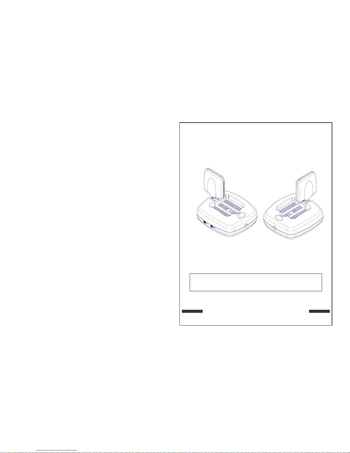
2.4 GHz WIRELESS
VIDEO SENDER SYSTEM
MODEL: VS6367
06/03
This product broadcasts over public airwaves and its
video and audio signals may be intercepted without your
consent.
Page 2
SAFETY INSTRUCTIONS
IMPORTANT SAFEGUARDS
All the safety and operating instructions should be read before the
appliance is operated and retained for future reference.
1. HEED WARNINGS - All warnings on the appliance and in the operating
instructions should be adhered to.
2. FOLLOW INSTRUCTIONS - All operating instructions should be
followed.
3. WATER AND MOISTURE - Do not use this video product near water -
for example, a bath tub, wash bowl, kitchen sink, laundry tub or swimming
pool, or in a wet basement.
4. POWER SOURCES - This product should be operated only from the type
of power source indicated on the marking label.
5. OVERLOADING - Do not overload outlets and extension cords, which
can result in a risk of fire or electric shock.
6. SERVICING - Do not attempt to service this product yourself. Opening or
removing covers may expose you to dangerous voltage or other hazards.
Refer all servicing or repairs to qualified service personnel.
7. DAMAGE REQUIRING SERVICE - Unplug this product from the wall outlet
and refer servicing or repairs to qualified service personnel under the following
conditions:
a. When the power supply cord or plug is damaged.
b. If liquid has been spilled or objects have fallen into the product.
c. If the product has been exposed to rain or water.
d. If the product does not operate normally by following the operating instructions.
Adjust only those controls that are covered by the operating instructions.
e. If the product has been dropped or the cabinet has been damaged.
f. When the product exhibits a distinct change in performance.
2
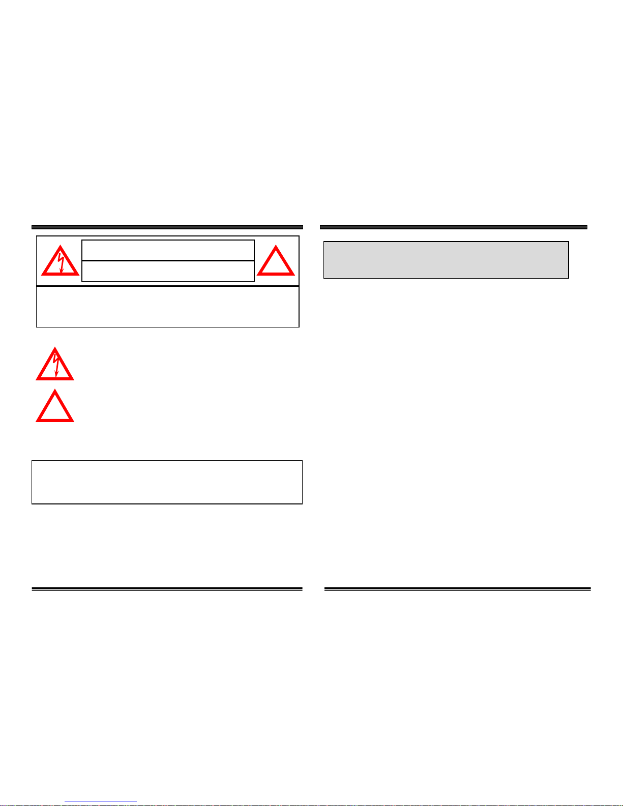
Explanation of two Symbols
The lightning flash with arrowhead symbol, within an equilateral
triangle, is intended to alert the user to the presence of uninsulated
"dangerous voltage" within the product's enclosure that may be of
sufficient magnitude to constitute a risk of electric shoc k to persons.
The exclamation point within an equilateral triangle is intended to
alert the user to the presence of important operating and maintenance(servicing) instructions in the literature accompanying the appliance.
THE GRAPHIC SYMBOLS WITH SUPPLEMENTAL MARKING ARE ON
THE BOTTOM OF THE SYSTEM.
WARNING: To prevent fire or shock hazard, do not expose this
appliance to rain, water, or wet locations. Do not
insert any metallic object through the ventilation grills.
IMPORTANT SAFETY INSTRUCTIONS:
This wireless Audio/Video equipment is provided with a polarized alternatingcurrent line plug (a plug having one blade wider than the other). This plug will
fit into the power outlet only one way. This is a safety feature. If you are unable
to insert the plug fully into the outlet, try reversing the plug. If the plug still fails
to fit, contact your electrician to replace your obsolete outlet. Do not defeat the
safety purpose of the polarized plug.
!
CAUTION
RISK OF ELECTRIC SHOCK. DO NOT OPEN.
CAUTION:TO REDUCE THE RISK OF ELECTRIC SHOCK, DO NOT REMOVE
COVER (OR BACK). NO USER-SERVICEABLE PARTS INSIDE.
REFER SERVICING TO QUALIFIED SERVICE PERSONNEL.
!
1
Page 3

8. REPLACEMENT PARTS - When replacement parts are required, be sure the
service technician has used replacement parts that are specified by the manufacturer
or have the same characteristics as the original part. Unauthorized substitutions
may result in fire, electric shock, or other hazards.
9. SAFETY CHECK - Upon completion of any service or repairs to this video
product, ask the service technician to perform safety checks to determine if the
video product is in proper operating condition.
10. An appliance and cart combination should be moved with care.
Do not place this equipment on an unstable cart, stand, or table. The equipment
may fall, causing serious injury to a child or adult, and serious damage to the
equipment. Wall or shelf mounting should follow the manufacturer's instructions
and should be done with a mounting kit approved by the manufacturer.
Note:
This equipment has been tested and found to comply with the limits For a Class B
digital device, pursuant to Part 15 of the FCC Rules. These limits are designed to
provide reasonable protection against harmful interference in a residential
installation. This equipment generates, Uses and can radiate radio frequency
energy and, if not installed and used in accordance with the instruction, may cause
harmful interference to radio communications. However, there is no guarantee that
interference will not occur in a particular installation. If this equipment does cause
harmful interference to radio or television reception, (which can be determined by
turning the equipment off and on), the user is encouraged to try to correct the
interference by one or more of the following measures:
• Reorient or relocate the receiving an tenna.
• Increase the separation between the equipment and receiver.
• Connect the equipment into an outlet on a circuit different from that to which
the receiver is connected.
• Consult the dealer or an experienced radio or television technician for help.
• Complies with Canada 210
FCC CLASS B NOTICE
3 4
CHAPTER TABLE OF CONTENTS PAGE
1. CONTROLS AND FUNCTIONS
WIRELESS SENDER ........................……………………..…..… .…...................5
WIRELESS RECEIVER ......................................…........………………..……….6
2. INSTALLATION OF WIRELESS SENDER …...…............……….....…......…...7
3. INSTALLATION OF WIRELESS RECEIVER
OPERATION WITH TV (USING RCA CABLES) ……...…………..…..………8
OPERATION WITH TV (USING COAXIAL CABLES) ...…...…………......….9
OPERATION WITH TV & VCR …............................…….……………............10
4. SYSTEM OPERATION
USING THE IR EXTENDER REMOTE CONTROL FEATURE ....……..……11
HOW TO USE THE IR EXTENDER ACCESSORY ................………….….…12
5. TROUBLE SHOOTING ..................................................…………………........ 13
6. SPECIFICATIONS …...……………………………………….……….…..……14
Congratulations on your purchase of the Deluxe Lorex 2.4 GHz
Wireless Video Sender System with IR extender. This system easily
connects to any T.V., allowing you to view your Satellite, D VD or
Security Camera from another room, of up to 300ft distance (open
space). The system also integrates an IR extender which allows you to
control the audio or video source from another room using your existing
TV or VCR remote control.
To learn more about this product and for a complete
listing of Lorex products, please visit us at:
www.strategicvista.com
Page 4

WIRELESS SENDER
1. CHANNEL SELECTOR SWITCH
Used to manually select channel
settings 1-4.
2. ON/OFF POWER SWITCH
ON/OFF power Switch:
Ensure this switch is set to OFF
before plugging the system into
an electrical outlet.
3. 2.4 GHz PATCH ANTENNA
High gain patch antenna sends
audio and video signals to the
wireless receiver.
4. DC IN JACK
Power source for the sender.
5. VIDEO INPUT JACK (YELLOW)
RCA jack for video input connector.
SENDER BACK
CONTROLS AND FUNCTIONS
5
1. 2.4 GHz PATCH ANTENNA
High gain patch antenna receives
audio and video signal from the
wireless sender.
2. CHANNEL SELECTOR SWITCH
Used to manually select channel
settings 1-4.
3. ON/OFF POWER SWITCH
ON/OFF power switch:
Ensure this switch is set to OFF
before plugging the system into
an electrical outlet.
4. RF OUT JACK
Used to connect the receiver to a
TV using the supplied coaxial cable.
5. DC IN JACK
Power source for the receiver.
6. VIDEO OUTPUT JACK (YELLOW)
RCA jack for Video output connector.
(when using RCA connector)
7. AUDIO OUTPUT JACKS
R (RED) & L (WHITE)
RCA jacks for Audio output connector.
(when using RCA connector)
8. CHANNEL 3/4 SELECTOR SWITCH
Used to view picture on television
when using Coaxial cable (preset
to channel 3).
9. POWER INDICATOR
Shows system status.
10. IR RECEIVER FOR REMOTE
CONTROL
Receives remote control signal from
the video source.
CONTROLS AND FUNCTIONS
WIRELESS RECEIVER
NOTE
6
RECEIVER FRONT & SIDE RECEIVER BACKSENDER FRONT & SIDE
6. AUDIO INPUT JACKS
R (RED) & L (WHITE)
RCA jacks for audio input connector.
7. IR EXTENDER INPUT
Connection for the IR extender
accessory.
8. POWER INDICATOR
Shows system status.
NOTE
3
4
5
6
7
2
1 8
1
3
2
10
8
4
7
9
56
Page 5

1. Connect one end of the RCA cables to the Audio/Video jacks of the
Sender; the other end to the Audio/Video Out jacks of the VCR/Satellite/DVD.
Ensure that the yellow, red and white plugs match the yellow, red and white jacks
on both the VCR/Satellite/DVD and the Sender.
2. Plug one end of the supplied AC Adapter (9V 500 mA adapter) into the back of
the sender; the other end into an electrical outlet. The system is defaulted to
channel 1. Turn the sender on and ensure that the sender and receiver are set
to the same channels.
Ensure the Power Switch on the Sender is turned OFF prior to
proceeding with the following steps.
INSTALLATION OF SENDER
CONNECTING A TRANSMITTER SIGNAL FROM YOUR
VCR/SATELLITE/DVD
NOTE
STEP 1:
7
CONNECTING A RECEIVER TO A T.V. USING RCA CABLES
You have two options to connect the Receiver: A) Using RCA Cables (see
below; or B) Using Coaxial Cables, please refer to page 9 of this manual.
Ensure the Power Switch on the Receiver is turned OFF prior to
proceeding with the following steps.
NOTE
1. Place the wireless receiver near your television (or monitor).
2. Connect one end of the RCA cables to the Audio/Video jacks at the back
of the Receiver. Plug the other end of the RCA cables into the Audio/Video
In jacks on your television. Be sure the yellow, red and white plugs match
the yellow, red and white jacks on both the receiver and TV.
3. Connect one end of the supplied 9V 500 mA AC Adapter into the back of
the receiver; the other end into an electrical outlet. Turn the receiver ON.
The system is defaulted to channel 1. Ensure to select A/V channel on the VCR.
(refer to your T.V./VCR owners manual on setting to Video (Aux) mode).
4. Turn your T.V. to AV (Aux. Mode) to view the picture on your second T.V.
5. Adjust the antenna on both the sender and receiver as necessary for
optimum viewing.
Ensure that the sender and receiver are set to the same channels.
NOTE
STEP 2:
8
INSTALLATION OF RECEIVER
A)
NOTE
TO UTILIZE YOUR REMOTE CONTROL, PLEASE SEE
PAGE 11 “USING THE IR EXTENDER FEATURE WITH
YOUR REMOTE CONTROL”.
VCR/SATELLITE/DVD
(SUPPLIED)
(NOT SUPPLIED)
(SUPPLIED)
Page 6

INSTALLATION OF RECEIVER
CONNECTING A RECEIVER TO A T.V. USING COAXIAL CABLES
Ensure the Power Switch on the Receiver is turned OFFprior to
proceeding with the following steps.
NOTE
Ensure that the sender and receiver are set to the same channels.
NOTE
STEP 2:
1. Place the wireless receiver near your television (or monitor).
2. Connect one end of the coaxial cable to the back of the Receiver. Plug the other
end of the coaxial cable to the television.
3. Connect one end of the supplied 9V 500 mA AC Adapter into the back of the
receiver; the other end into an electrical outlet. Turn the r eceiver ON. The system
is defaulted to channel 1.
4. Search channels 1 through 4 by using Channel Selector Switch on the Receiver
and Sender.
5. Turn your T.V. to channel 3 to view the picture from your second T.V.
6. Adjust the antenna on both the sender and receiver as necessary for
optimum viewing.
9
Ensure the Power Switch on the Receiver is turned OFF before
proceeding with the following steps.
Ensure that the sender and receiver are set to the same channels.
NOTE
INSTALLATION OF RECEIVER
CONNECTING A RECEIVER TO A REMOTE TV THROUGH A VCR
10
NOTE
1. Connect one end of the RCA cables to the Audio/Video jacks located at the back
of the receiver. Plug the other end of the RCA cables into the Audio/Video In
jacks on your VCR.
2. Connect one end of other RCA cables to the Audio/Video jacks on your Television.
Plug the other end of the RCA cables into the Audio/Video Out jacks on your VCR.
3. Turn both the Sender and Receiver ‘ON’. Set your TV to Video mode to view
the signal from the T.V. Ensure to select A/V channel on the VCR. (consult your
T.V./VCR owners manual on setting to Video (Aux) mode).
4. Turn your T.V. to AV (Aux. Mode) to view the picture on your second T.V.
5. Adjust the antenna direction on both the sender and receiver as necessary for
optimum viewing.
B)
(SUPPLIED)
Page 7

The system not only allows you to send crisp audio/video from one area to
another, it also gives you the ability to control the source using your existing
remote control device. It converts the infrared (IR) signal emitted by your
remote control to a radio frequency (RF) signal in UHF band at the receiver
and sends it back to the sender where the RF signal is converted back to
the original IR signal and beamed to the audio/video device.
The following states the use of the remote control feature to control your A/V
equipment by using the existing remote control.
1. Simply connect the IR extender plug into the back of the sender and
position the IR extender near the A/V source equipment’s front panel.
Sometimes, it may be difficult or even impossible to orient the sender unit
such that it can be “seen” (face-to-face) with the A/V equipment you wish to
control. (This happens when surface is not adequate for this or you wish
to remotely control A/V equipment in different locations withoutre-orienting
the LOREX sender). In this case, using the extender will be more
convenient.
USING THE IR EXTENDER FEATURE WITH YOUR
REMOTE CONTROL
11
SYSTEM OPERATION
HOW TO USE THE IR EXTENDER ACCESSORY
The IR extender connects to the sender through its own special
connector plug. The extender emits an IR signal to your A/V device
with the remote signal. To use the IR extender, follow the instructions
below.
1. Plug the IR extender into the back of the sender (see page 5).
2. Orient the end of the IR extender so that it points in the general
direction of IR sensors on the source device you wish to control.
Cut a length of provided fastener strip to secure the IR extender in
it’s position.
3. Position the receiver so that your remote control signal can strike
the IR window on the bottom from of the unit. To use your remote
control, point it at the front of the receiver.
12
SYSTEM OPERATION
UHF
Remot
e
Contro
l
1 2 3
4 5 6
7 8 9
0
VECCOM
VECCOM
+ -
Receiv
er
Sende
r
IR Extender
Input
IR EXTENDER
Page 8

If the system does not function properly, check the following points before
contacting the service center:
FOR MORE INFORMATION OR A COMPLETE LIST OF
PRODUCTS, VISIT OUR WEBSITE AT:
www.strategicvista.com
No power
(no picture/sound)
Poor reception
Picture flickering
Picture too bright,
or too dark
Problems
Causes and Remedies
Video Source Receiver/Sender
- AC adapter not plugged in
- Power switch not turned ON
- TV or Monitor not turned ON
- Improper A/V or coaxial
cable connection
- Video source/device not
connected to sender
- AC adapter not plugged in
- Power switch not turned
ON
- Adjust antenna direction
- Improper channel 1-4
selection
- Video source/device not
connected to sender
- AC adapter not plugged in
- Power switch not turned
ON
- Strong spot light in the
field of view
- Lighting source in the
field of view
- Adjust brightness control on
TV/monitor
- Adjust antenna direction- Adjust antenna direction
Picture rolls and jumps
or scrambled picture
No power
(no picture/sound)
Poor Reception
Picture flickering
Picture too bright
or too dark
13
TROUBLE SHOOTING
Power Consumption
Operating Frequency
Channel selection
Modulation
Video input level
Audio input level
Antenna
LED indicator
Operating Temperature
Dimensions
Weight
Frequency
Output level
Antenna
Operating Temperature
Power Consumption
Dimensions
Weight
9V DC Adapter, 500 mA
2.4 to 2.4835 GHz
4 channel
FM (video and audio)
1 V p-p @ 75 Ohms
1 V p-p @ 600 Ohms
Patch
Power
0°C - 50°C
5” x 4.8” x 2” (12.9 x 12.2 x 5.2 cm)
227 g (8 oz)
433.92 MHz
1 V p-p @ 75 Ohms (video), 1 V p-p (audio)
Patch
0°C - 50°C
9V DC Adapter, 500mA
5” x 4.8” x 2” (12.9 x 12.2 x 5.2 cm)
246 g (8.7 oz)
Sender
Receiver
2 - AC Power Adapters
2 - Audio/Video RCA Cables
1 - Coaxial Cable
WIRELESS RECEIVER
Because our products are subject to continuous improvement, SVC reserves the right
to modify product Designs and Specifications without notice and without incurring any
obligation. E & OE.
WIRELESS SENDER
14
SPECIFICATIONS
SYSTEM INCLUDES
 Loading...