

Page 1
It’s all on the web
Quick Set-up Guide
Image Sensor 1/4” Color CCD
Effective Pixels 510 H x 492 V (250K pixels)
Scanning System 525 Lines 2:1 Interlace
Scanning Frequency 15.734KHz(H), 59.94Hz(V)
Resolution 330 TV Lines
Shutter Speed Auto 1/60 – 1/10,000 SEC
S/N Ratio more than 48dB (AGC off)
Sync. System Internal
Minimum Illumination 1.0 LUX (without LED)
White Balance AWB
Video Output VBS 1.0 Vp-p (75 Ω load)
Lens Varifocal (4.0 - 9.0 mm)
Power Supply
DC12V ± 10%
Power Consumption 100mA (LED’s off)/ 300mA with
LED’s on (DC12V)
Operating Temperature 14ºF to 113ºF (-10ºC to 45ºC)
Operating Humidity 90% RH max.
Diameter 125 mm
Base Composition Cast Iron
Dome Composition Polycarbonate
4. View the Camera Picture
BUSINESS & HOME
a. Turn on your TV
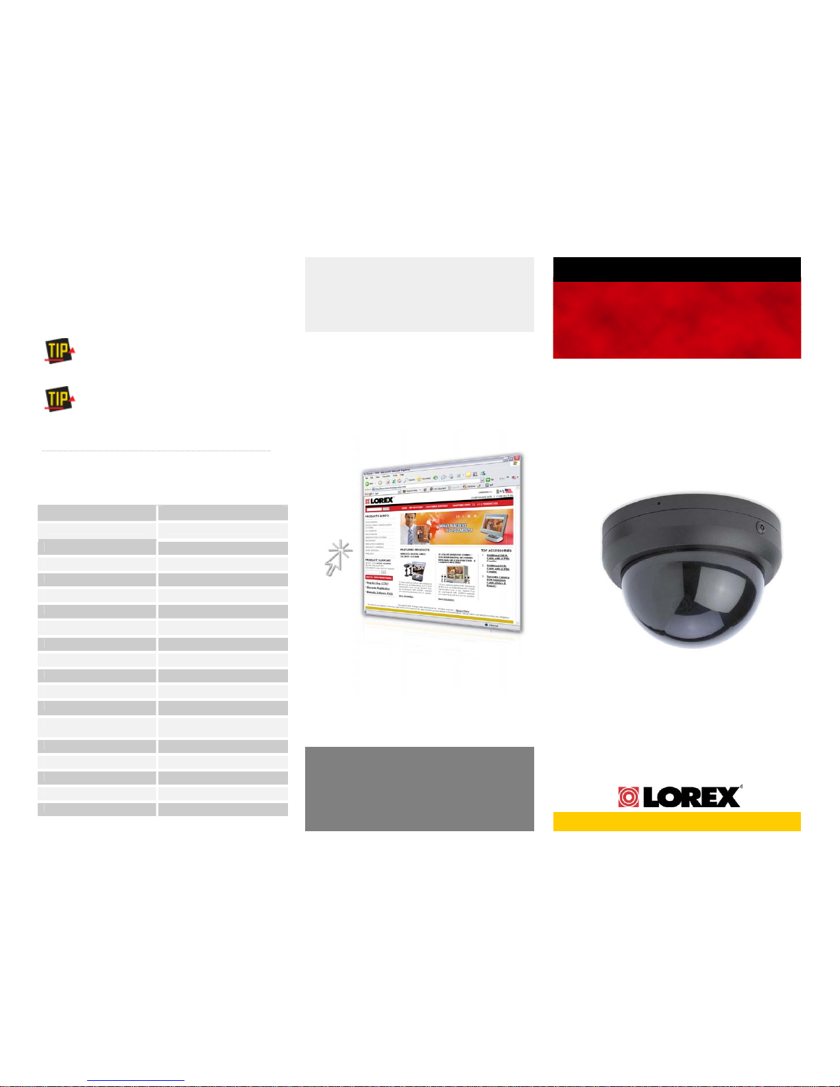
HIGH IMPACT VANDAL RESISTANT
DAY/NIGHT COLOR DOME CAMERA
with VARIFOCAL LENS
b. To view the picture from the camera, switch to
the Video mode (i.e. AV, or AUX mode).
Refer to your VCR’s (or camera’s) owner’s manual
for instructions for connecting the VCR
Product Information
User Manuals
Quick Start Guides
Specification Sheets
Software Upgrades
Firmware Upgrades
Model VQ1634CL
This camera can also be connected to a video
cassette recorder (VCR) or Digital Video Recorder
(DVR) that provides RCA camera cable input jacks.
Specifications
VISIT
www.lorexcctv.com
Strategic Vista International Inc.
Copyright © 2005 Strategic Vista International Inc
As our products are subject to continuous improvement, SVII
and its subsidiaries reserve the right to modify product design,
specifications and prices, without notice and without incurring
any obligation. E&OE
Page 2
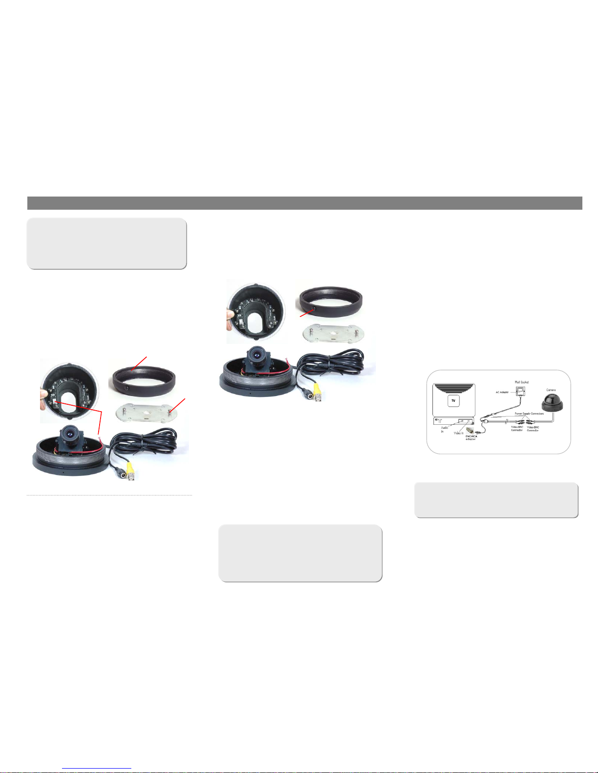
1. Confirm Package Contents 2. Mount the Video Camera
3 Connect the Camera to the TV
VQ1634R Camera
60 ft extension cable
AC Adapter
BNC/RCA adapter
a. Male BNC connector (extension cable) to
female BNC connector (camera).
b. Male power jack (extension cable) to female
power jack (camera).
c. Male BNC connector (extension cable) to
BNC/RCA (adapter).
d. Female power jack (extension cable) to male
power jack (AC adapter).
e. RCA end of BNC/RCA (adapter) to TV video in.
a. Install the camera mounting bracket to the ceiling
b. Mount the camera base to the ceiling by lining up
the camera base with the camera mounting bracket
then tighten the screws.
Before installation:
1. Unscrew the camera ring from the camera base
2. Unplug the LED power connector inside the
camera
3. Loosen screws on the metal bracket and
remove the bracket
Dome
Camera
ring
Tamper
proof
screw
Camera
mounting
bracket
1
Features:
• 1/4” Color CCD
• Optical Zoom and Focus adjustment
• 16 IR LED’s provide IR range up to 20 ft
(approx. 6M)
• 360º manually adjustable viewing direction
• High impact dome can withstand a strike from a
10 lb. sledge hammer.
c Plug in the LED power connector from the
camera base to the LED plug in the dome
d. Screw the camera ring to the camera base to
attach the dome.
e. Screw in the tamper proof screw with the Allen
key (included).
f. Run the supplied 60 ft extension cable between
the security monitor (or TV) and the camera.
The 60 ft extension cable has a male BNC connector
and male power connector on one end. The other
end of the cable has a male BNC connector and a
female power connector.
3
2
6ft cable
female BNC
power
jack
Camera base
The TV must have a video in port or additional
hardware my be required
 Loading...