

Page 1
QUICK START GUIDE
www.lorexcctv.com
Product Information
User Manuals
Quick Start Guides
Specification Sheets
Software Upgrades
Firmware Upgrades
www.lorexcctv.com
VISIT:
Lorex Technologies Inc.
Copyright © 2008 Lorex Technologies Inc.
As our products are subject to continuous
improvement, Lorex reserves the right to
modify product design, specifications and
prices, without notice and without incurring
any obligation. E&OE
It’s all on the Web!
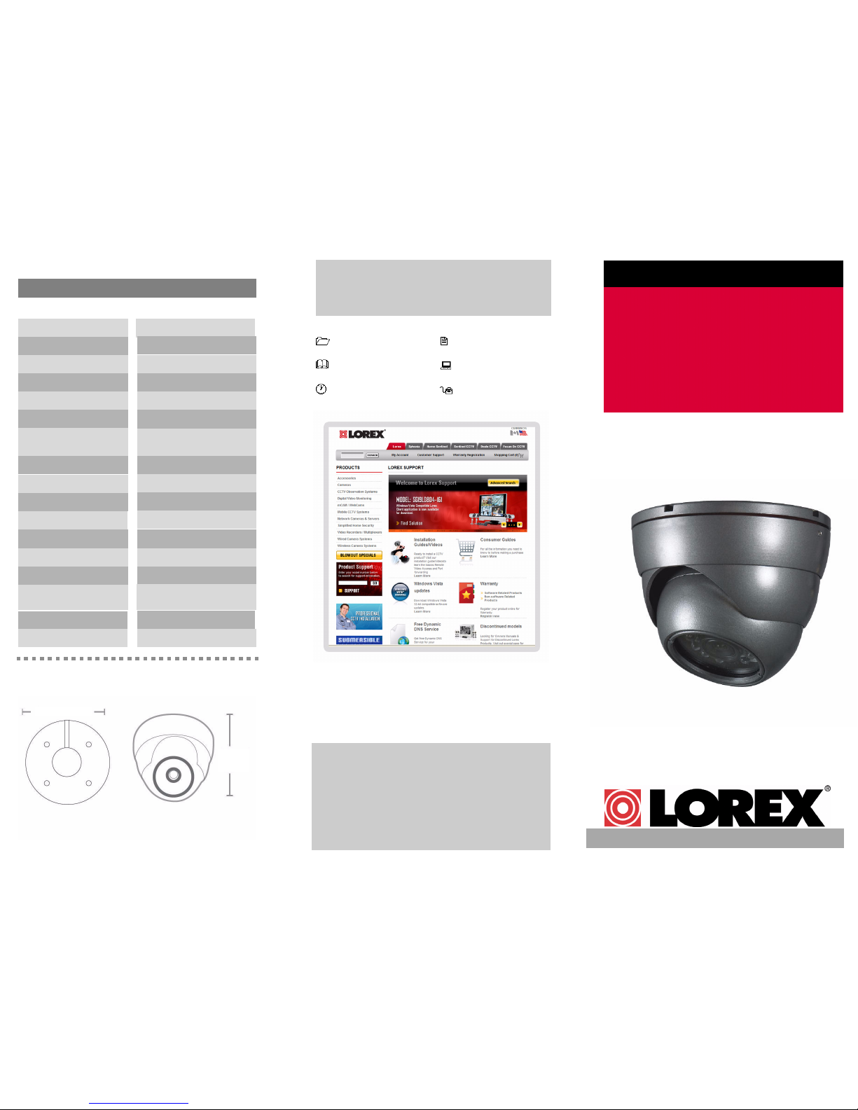
Camera Specifications
PROFESSIONAL COLOR
SURVEILLANCE DOME
CAMERA
Day/Night, Weatherproof, Vandal
Resistant, Advanced Image Sensor
Specfications:
Image Sensor
Video Output
Horizontal Resolution
FOV (diagonal)
Termination
Lens / Lens Mount
S/N Ratio
Sync. & Scan. Systems
IR Range
Power Consumption
70 Degrees
Video: BNC Female
3.6 mm F2.0/Fixed
> 48dB
Internal; 2:1 Interlace
Up to 40 ft (12 m); 12 LEDs
220 mA max
Operating Temp.
14°F ~ 122°F
(-10°C ~ 50°C)
Comp. 1.0 Vpp @ 75ohm
Iris & Shutter Speed AES; 1/60 ~ 1/50,000 sec.
Power Requirement 12V DC ±10%
Dimensions
DIA: 3.7” (94 mm)
Minimum Illumination
Video Format / Pixels
0.5 LUX @ F1.2 (IR Off)
0 LUX (IR LEDs ON)
Weight 0.85 lbs / 386 g
1/4” AIS
NTSC: 656 (H) x 492 (V)
480 TVL
imensions
3.7in/94mm
3.1in/
75mm
MODEL: VQ1536HRB
English Version 1.0
Page 2
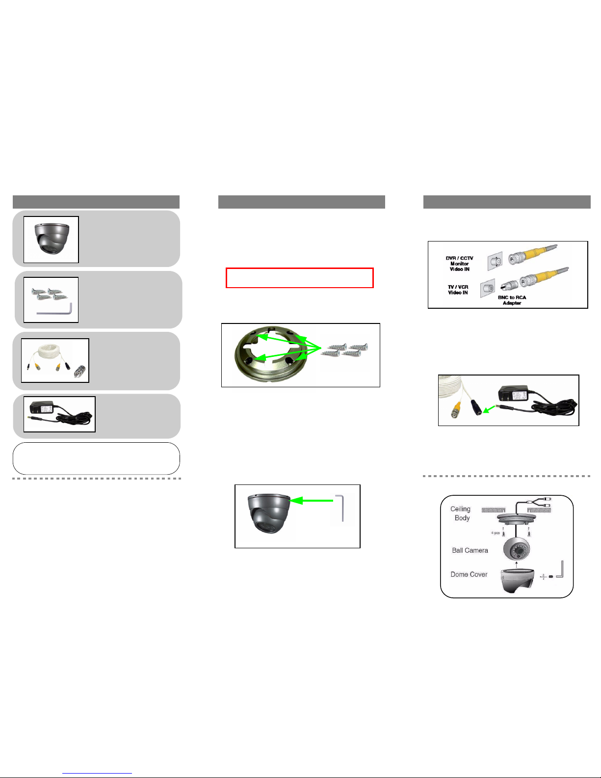
4. Connect the BNC end of the Camera Cable to an
extension cable, or directly to a DVR /
Observation System or to a TV/VCR.
Note: Note: Connect the BNC to RCA Adaptor as needed to allow for
proper connectivity.
5. Connect the A/C Power Adaptor to the 60ft
Extension cable (Black connector). Plug the
Power adaptor to a wall outlet.
Note: Note: If the onscreen display is blurry, you may need to set the
Monitor Impedence switch to 75 ohms.
Figure 3.0 Connect the BNC cable to a DVR, CCTV, monitor or TV
Figure 4.0 Connect power cable from BNC extension cable to
the AC Power Adaptor (included).
Contents Installing the camera
1 x Vandal Resistant
Weatherproof Day/Night
Dome Camera
Prior to installing the camera, make sure of the
following:
• Decide to run the cables through the wall/ceiling (drilling required),
or along the wall/ceiling.
• If you run the cables along the wall/ceiling, you must run the cables
through the opening in the camera base, then tuck the cable into
the notch on the base. This will keep the camera base flush to the
wall/ceiling when mounted..
To install the camera:
1. Mount the Camera Base to the ceiling or wall using
the provided screws.
Note: You may need to disassemble the camera using the provided
Allen key. Loosen the tighening screws located on the outer ring of the
Dome Cover.
2. Position the Ball Camera to the desired position
and angle.
3. Position the Dome Cover over the Ball Camera.
Holding the cover firmly in place, use the Allen key
to tighten the screws on the outer ring of the Dome
Cover.
Note: This camera includes a mechanical Auto IR Cut filter. When
conditions change between day/night, an audible clicking noise will be
heard coming from the camera. This clicking is normal, an indicates that
the IR filter is working.
ATTENTION - Test the camera prior to selecting a permanent
mounting location by temporarily connecting the cameras and
cables to the TV,VCR, DVR or Observation System.
Figure 1.0 Attach the base to the mounting surface.
Figure 2.0 Tighten the dome cover using the Allen key.
Features
• 1/4” Advanced Image Sensor (AIS) provides a High
Resolution image (480 TV Lines)
• Auto Mechanical IR Cut Filter removal function ensures
accurate color reproduction
• Durable Weatherproof Indoor/Outdoor camera*
• 3-axis design allows for wall or ceiling mounting
• Enhanced Night Vision Capability — up to 40 ft /12 m **
* Not recommended for submersion in water
** IR Illumination range of 40 ft. (12 m) under ideal conditions.
Objects at or beyond this range may be partially or completely
obscured, depending on the camera application.
WARNING - A REGULATED UL/CSA APPROVED 12V DC 500mA
power supply is REQUIRED for use with this camera. Use of a non-regulated, non-conforming power supply can damage this product and will
void the warranty.
4 x Mounting screws
1 x Allen key
Connecting the camera
Setup Diagram:
1 x 60ft. BNC/Power
Extension Cable
1 x BNC to RCA
Adaptor
1 x AC Power Adaptor
 Loading...