

Page 1
Product Information
User Manuals
Quick Start Guides
Specification Sheets
Software Upgrades
Firmware Upgrades
VISIT
Copyright © 2009 Lorex Technology Inc.
Camera Specifications
www.lorexcctv.com
Lorex Technol og ie s I nc .
Copyright © 2009 Lorex Technologies Inc.
As our products are subject to continuous
improvement, Lorex reserves the right to
modify product design, specifications and
prices, without notice and without incurring
any obligation. E&OE
QUICK START GUIDE
It’s all on the Web!
www.lorexcctv.com
Dimensions:
Image Sensor High Resolution 1/4” Sensor
Lens / Lens Mount
Video Format / Pixels
Horizontal Resolution
Minimum Illumination
Termination
IR / Night Vision Range
FOV (diagonal)
S/N Ratio
Sync. & Scan. Systems
Video Output
Power Consumption
NTSC: 656(H) x 492 (V)
450 TVL
3.0 LUX
Video: BNC Female
Power: Barrel Female
N/A
70 Degrees
> 48dB
Internal; 2:1 Interlace
Comp. 1.0 Vpp @ 75ohm
90 mA max
Operating Temp.
Dimensions
LxWxH
14°F ~ 122°F
(-10°C ~ 50°C)
4.72” x 4.72” x 2.96”
120 mm x 120 mm x 75 mm
3.6 mm F2.0/ Fixed
Iris & Shutter Speed AES; 1/60 ~ 1/50,000 sec.
Power Requirement 12V DC +/- 10%
Weight (with stand) 0.62 lbs / 0.28 kg
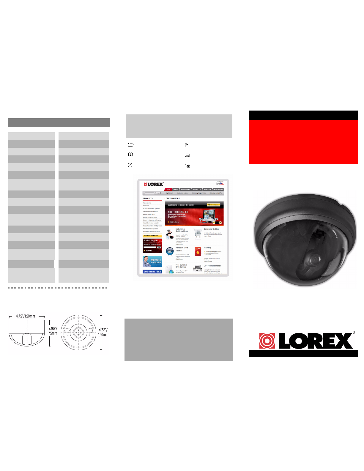
COLOR SURVEILLANCE
DOME CAMERA
English Version 1.0
MODEL: VQ1137H
Page 2
6. Attach the dome cover and dome ring. Make sure
the slot on the dome cover is aligned with the lens.
Screw the dome ring onto the base.
Connecting the camera
1. Connect the BNC female video cable from the
dome camera to the supplied BNC/Power
extension cable. Connect the BNC extension
cable to a DVR, observation system, TV, or VCR.
NOTE:
Connect the BNC to RCA Adaptor as needed to allow
for proper connectivity. See figure below
.
2. Connect the power cable from the dome camera to
the power extension cable. Connect the power
extension cable to the supplied AC adaptor.
Figure 4.0 Attach the dome cover and screw the dome ring onto the base
Figure 5.0 Full connection diagram
Contents
1 x Mini Color Dome
Camera
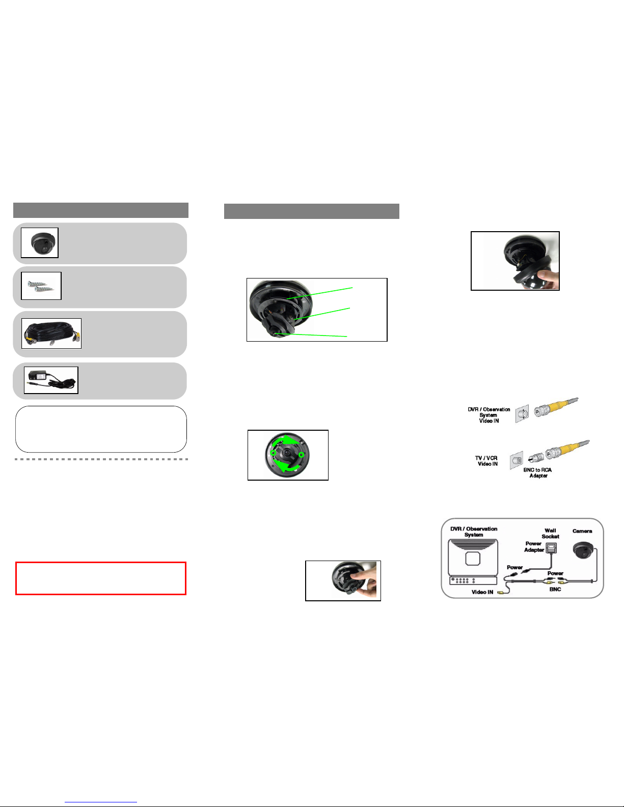
To mount the camera:
1. First, select the general direction the camera will
be facing.
2. Mount the camera to the desired position on the
ceiling using the provided mounting kit.
3. Using a Phillips screwdriver (not included), loosen
the two screws on the support ring and rotate the
camera horizontally (max. 180º) as needed (see
Figure 2.0).
Note:
If you remove the screws from the support ring, you can
rotate the camera up to 180º. If you only loosen the screws, you
can rotate camera up to 90º.
4. Slightly loosen the two screws on the support
arms and angle the lens vertically as needed (see
Figure 3.0).
5. Once you have set the position and angle for the
lens, firmly tighten the screws on the support ring
and support arms.
Figure 1.0 Mount the base
Support
ring
Support
arms
Lens
Figure 2.0 Loosen the screws and rotate the ring
WARNING - A regulated, UL/CSA approved 12V
DC 300mA power supply is required for use with
this camera. Use of a non-regulated, nonconforming power supply can damage this
product and will void the warranty.
2 x Mounting Screws
Features:
• High Resolution Image Sensor—produces sharp
and clear video
• Fixed IR Filter provides accurate color
reproduction
• 3.6 mm lens provides a wide viewing angle
• Industry standard BNC video connection
• Ceiling mountable
1 x 33ft. BNC/Power
Extension Cable
1x BNC to RCA Adapter
1 x AC Power Adaptor
ATTENTION - Test the camera prior to selecting a
permanent mounting location by temporarily connecting
the cameras to an observation system.
Installing the camera
Figure 3.0 Loosen the screws and adjust the angle of the lens
 Loading...