

Page 1
16 CHANNEL COLOR
MULTIPLEXER
Instruction Manual
www.strategicvista.com
Please be sure to read carefully and follow all the
safety information.
Keep the manual in a safe place for future reference.
Model: SGX1600
Page 2

INTRODUCTION
Congratulations on your purchase of the 16 Channel Color Multiplexer from Lorex.
The 16 Channel Multiplexer facilitates an advanced security system on any slave monitor. Connect up to 16
cameras to the Multiplexer and view all 16 locations simultaneously. Seven different display modes are
available, offering a wide variety of viewing options.
When used in conjunction with a professional security recorder (such as a time lapse VCR or a DVR), the
16 Channel Multiplexer simultaneously records each camera in Full-Screen, allowing the user to playback
recordings in Full Screen or Split Screen. Pixel-based Motion Detection is also included.
To learn more about this system or to find out more about other products available, please visit our website
at www.strategicvista.com
FEATURES
16 Channel Color Multiplexer Features
• Full Duplex Multiplexing: 16 cameras can record / playback / display live video at the same time
• Multiplexing function supports from 4 to 16 channels
• Viewing options: 7 different display modes including: Full screen, Quad, 7 Ch, 9 Ch, 10 Ch, 13 Ch, 16 Ch
• Display modes are selectable during live viewing or playback
• On Screen Display and Real Time Clock Function
• Picture in Picture, 2x digital zoom
• Digital pixel-based motion detection
• Picture adjustable by channel
• 16 alarm inputs, one alarm output
• Video Loss alarm
• Memory record of up to 50 events
• RS-232/485 external host control
: The 16 Channel Multiplexer is normally used in conjunction with a security recorder, such as a Time
NOTE
Lapse VCR or a DVR. For instruction on connection to a VCR / DVR, please refer to the diagrams
in the Appendices.
1
Page 3
SAFETY WARNING
All the safety and operating instructions should be read before the appliance is operated. The improper
operation may cause irreparable damage to the appliance.
• Please lift and place this equipment gently.
• Do not expose this equipment under to direct sunlight.
• Do not use this equipment near water or in contact with water.
• Do not spill liquid of any kind on the equipment.
• Do not unplug the power connector before turn the power off correctly.
• This equipment should be operated using only the power source from standard package.
• Unauthorized repair or parts substitutions may result in fire, electric shock or other hazards.
• Do not switch the Power On & Off within short period (within 3 seconds).
• Do not attempt to service this equipment by yourself. Refer all servicing to qualified service personnel.
• This unit should be operated only from the type of power source indicated on the manufacturer’s label.
• This installation should conform to all local codes.
CAUTION: TO REDUCE THE RISK OF ELECTRIC SHOCK, DO NOT
Explanation of two Symbols
The lightning flash with arrowhead symbol, within an equilateral triangle, is intended to alert
the user to the presence of uninsulated "dangerous voltage" within the product's enclosure that
may be of sufficient magnitude to constitute a risk of electric shock to persons.
The exclamation point within an equilateral triangle is intended to alert the user to the presence
of important operating and maintenance-(servicing) instructions in the literature accompanying
!
the appliance.
CAUTION
RISK OF ELECTRIC SHOCK. DO NOT OPEN.
REMOVE COVER (OR BACK). NO USER-SERVICEABLE PARTS
INSIDE. REFER SERVICING TO QUALIFIED SERVICE
PERSONNEL.
!
2
Page 4

TABLE OF CONTENTS PAGE
1. SYSTEM INCLUDES -----------------------------------------------------------------------------
2. FRONT PANEL CONT ROLS -------------------------------------------------------------------
3. LED INDICATORS -------------------------------------------------------------------------------
4. MENU CONTROLS ------------------------------------------------------------------------------
5. MENU OPTIONS ----------------------------------------------------------------------------------
6. CHANNEL SETUP MENU -----------------------------------------------------------------------
7. BACK PANEL ---------------------------------------------------------------------------------------
8. AUTO SEQUENCING - ---------------------------------------------------------------------------
9. ALARM AND VIDEO LOSS ---------------------------------------------------------------------
10. RS232 REMOTE PROTOCOL -----------------------------------------------------------------
11. MOTION DETECTION ---------------------------------------------------------------------------
12. TROUBLESHOOTING ---------------------------------------------------------------------------
13. TECHNICAL SPECIFICATIONS --------------------------------------------------------------
4
4
6
6
7
8
9
10
10
11
12
13
13
14. OPTIONAL ACCES S ORI ES -------------------------------------------------------------------
15. APPENDIX #1 – TYPICAL CONFIGURATION --------------------------------------------
16. APPENDIX #2 –CONNECTION TO A PIR MOTION SENSOR ----------------------
17. APPENDIX #3 – CONNECTION TO A LOREX TIME LAPSE VCR
FOR ALARM RECORDING AND SYNCHRONIZATION ----------
18. APPENDIX #4 –PIN CONFIGURATIONS FOR CONNECTION TO PC ------------
19. APPENDIX #5 – RECORD RATE CHART -------------------------------------------------
14
15
16
17
18
19
3
Page 5
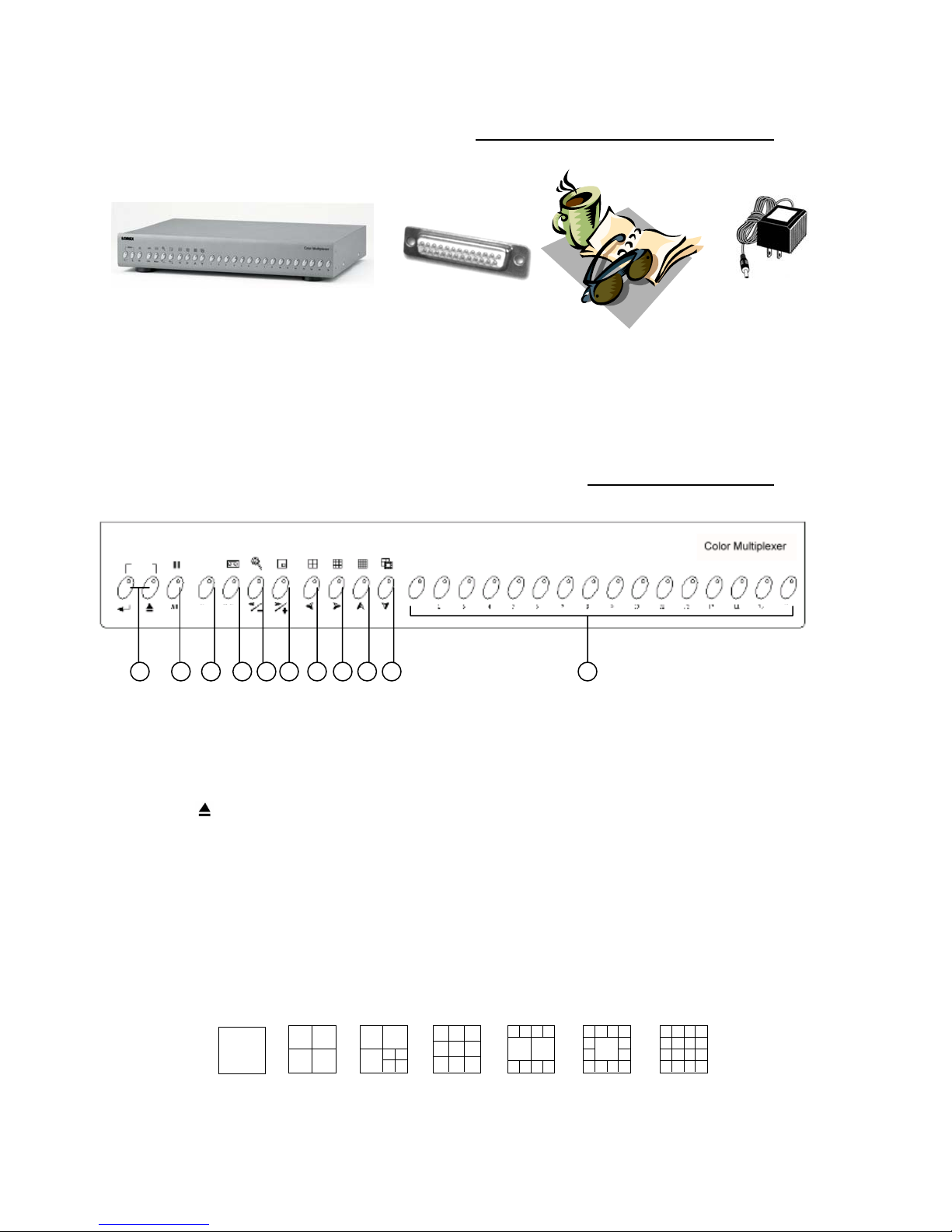
SYSTEM INCLUDES
12V DC Power Supply
16 Channel Color Multiplexer
CHECK YOUR PACKAGE TO MAKE SURE THAT YOU RECEIVED THE COMPLETE SYSTEM, INCLUDING THE COMPONENTS SHOWN ABOVE.
25 Pin Alarm
Connector
Owner’s Manual
FRONT PANEL CONTROLS
MENU
1.
MENU: ENTER / ESC
21
LIVE
Line Motion
53
4 6 7 8 9
1 16
10 11
Pressing these two buttons simultaneously activates the Main Menu.
a) ENTER [↲]: Selects Menu options to be edited in Menu mode.
Initiates and stops Auto Sequencing (refer to page 10 for more details).
b) ESC :Confirms changes to options in Menu mode.
Exits Menu mode and various other viewing modes.
2.
FREEZE [ II ]
a) Pressing this button Freezes all channels appearing on screen.
b) Pressing this button and ENTER simultaneously allows you to freeze individual channels when viewing a split-
screen display mode. Press channel buttons 1-16 to freeze / unfreeze each screen.
3.
LIVE
a) Pressing this button goes to Live viewing mode (escapes VCR mode).
Below are diagrams of the 7 different LIVE viewing modes.
Full Screen
Quad
7 CH 9 CH 10 CH
4
13 CH
16 CH
Page 6

b) Pressing LIVE and ENTER simultaneously allows you to swap camera screens in any viewing mode.
For example, you may want to view cameras 5-8 together in the 4 Channel (Quad) display mode.
After pressing the two buttons together, use the or buttons to navigate between cameras, and select the
camera screens that you wish to swap. When on the screen that you wish to change, press a Channel button (1-16)
to select the replacement camera. Once you have made the desired changes, press ESC to escape.
4.
VCR [ ]
a) Pressing this button enters VCR mode, enabling you to view playback from your VCR or DVR.
NOTE
: As this system has a Multiplexing feature, you are able to navigate between the different viewing modes
during video playback (provided that you recorded using the VCR output of the Multiplexer unit).
b) Pressing VCR and ENTER simultaneously allows you to swap camera screens in any viewing mode. Follow the
same instructions outlined in 3b in order to swap VCR camera screens with LIVE camera screens.
NOTE
: As this system has a Duplex Multiplexing feature, you are able to view both Live video and video Playback
from your VCR / DVR at the same time on a multi-screen display.
c) Pressing VCR and ZOOM simultaneously from Live viewing mode brings up the Menu from your Time Lapse VCR
or DVR. Press the two buttons again to exit VCR / DVR Menu mode.
5.
ZOOM [ ] /
a) Pressing this button activates the 2x2 Zoom feature. After pressing this button, a Full-Screen channel will appear
enlarged on screen, with a miniature picture of the Full-Screen channel appearing as a picture-in-picture. The
miniature picture has a ¼ size white outline depicting which section of the camera view is being zoomed in on. You
can press the ▲▼◄►arrow keys to move the Zoom area. To change between Full-Screen channels, simply
press Channel buttons 1-16. Press ESC to escape.
You can also Zoom in on cameras in VCR mode. While in Zoom, select the channel that you wish to view in VCR
mode, then press VCR and ENTER simultaneously.
b) This button also serves as the arrow key, which is used to scroll left or decrease values in submenu options.
6.
PICTURE-IN-PICTURE [ ] /
a) Pressing this button enters PIP display, with a Full-Screen Main Channel and a 1/16 sized Sub Channel. Move
the location of the sub-picture by pressing the ▲▼◄►arrow keys.
You can swap cameras being shown in the Main and Sub pictures by pressing PIP and ENTER simultaneously,
using the and buttons to scroll between selecting the Main / Sub camera. You can then select the specific
camera (1-16) that will replace the Main / Sub screen. Press ESC to confirm.
Also, you can view VCR playback and Live video simultaneously in PIP mode. To achieve this, press VCR and
ENTER simultaneously, and then follow the same process described above.
Press ESC to exit PIP viewing mode.
b) This button also serves as the arrow key, which is used to scroll left or decrease values in submenu options.
7.
QUAD DISPLAY MODE [ ] / ◄
a) Pressing this button goes to Quad (4 Channel) display mode.
b) This button also serves as the Left arrow key in Menu navigation, moves the sub-picture left in PIP mode, and scans
left in Zoom mode.
8.
9 CHANNEL DISPLAY MODE [ ] / ►
a) Pressing this button goes to a 9 Channel display mode.
b) This button also serves as the Right arrow key in Menu navigation, moves the sub-picture right in PIP mode, and
scans right in Zoom mode.
5
Page 7

9.
16 CHANNEL DISPLAY MODE [ ] / ▲
a) Pressing this button goes to a 16 Channel display mode.
b) This button also serves as the Up arrow key in Menu navigation, moves the sub-picture up in PIP mode, and scans
upward in Zoom mode.
10.
SELECT DISPLAY MODE [ ] / ▼
a) Pressing this button allows you to select between six different split-screen viewing modes (4 Ch / 7 Ch / 9 Ch /
10 Ch / 13 Ch / 16 Ch).
After pressing this button, press a valid Channel button (from 4-16, corresponding to the six options above) to select
the viewing mode. For example, if you want to view a 7 Channel display, press the Channel 7 button.
b) This button also serves as the Down arrow key in Menu navigation, moves the sub-picture down in PIP mode, and
scans downward in Zoom mode.
LED INDICATORS
On each button is a red LED indicator, which shows the system’s status and helps to navigate in Menu mode.
For example, when in PIP mode the following LED indicators turn ON for the following reasons:
PIP button – shows that you are in PIP mode
Four arrow keys – show that moving the subscreen via the arrow keys is possible
VCR button – shows that you can swap screens to view VCR playback in PIP mode
LIVE button – shows that you can swap screens to view other channels in PIP mode
ESC button – shows that you can exit PIP by pressing this button
When in doubt regarding which buttons are the right ones to press, the LED indicators are a helpful reference as
they show which keys are applicable in certain situations.
MENU CONTROLS
Pressing the ENTER and ESC buttons simultaneously to bring up the Menu screen.
Outlined below are the buttons used for navigation when using the Menu.
▲and ▼: Scroll up and down through menu options.
◄ and ►: Scroll sideways within a menu option that has been selected.
Makes selections when there is a choice between 2 options (such as: ON or OFF).
: Goes to the Channel Setup screen from the Main Menu.
Increases an alpha / numerical value of a menu option when editing it (when it is blinking).
: Returns back to the Main Menu from the Channel Setup screen.
Decreases an alpha / numerical value of a menu option when editing it (when it is blinking).
ENTER: Selects a submenu / an option in a submenu for browsing / modification.
ESC: Completes modification of a menu option; exits a menu.
6
Page 8

MENU OPTIONS
Upon entering the Menu, you will see the screen
shown to the right. Below is a description of each
Menu option:
Title Display
– Selects whether camera titles
appear on-screen.
Alarm Duration
– Set the length of the Alarm time
between 1~59 sec and 1~30 min.
Dwell Time
– Select how long a camera screen will
appear in Sequencing mode before switching to
the next screen. Programmable between 1~10 sec.
VCR Record Time
– Enter the speed at which your
VCR / DVR is recording. Refer to Appendix #5 for a
chart of recording Images per Second at each speed.
Alarm VCR Record Time
– Enter the speed at
TITLE DISPLAY ON OFF
ALARM DURATION 02 SEC
DWELL TIME 02 SEC
VCR RECORD TIME 002 HOUR
ALARM VCR RECORD TIME 002 HOUR
INT AUDIBLE ALARM ON OFF
EXT AUDIBLE ALARM O N OFF
EVENT MESSAGE LATCH ON OFF
SECURITY LOCK ON OFF
SET TIME 00/01/01 00:00:00 Y/M/D
EVENT LIST
BAUD RATE 9600 BPS
ID 000
REMOTE INTERFACE RS485 RS232C
SYSTEM RESET
which your VCR / DVR records when triggered by an Alarm.
NOTE
: Your DVR / Time Lapse VCR can synchronize recording speeds automatically if correctly
configured as per the diagram in Appendix #3 (with the SW OUT of the VCR / DVR
connected to the Record Pin on the 25 Pin Alarm Connector).
Int Audible Alarm
Ext Audible Alarm
Event Message Latch
– Activates / deactivates the alarm buzzer function of the multiplexer.
– Activates / deactivates the Alarm OUT function for external alarm devices.
– Controls how External Alarm and Video Loss alert icons [ and ]
appear on-screen. When Message Latch in ON, the Video Loss and External Alarm icons remain on screen
for the duration of the Event. When Message Latch in OFF, the icons only appear for only the programmed
Alarm Duration.
Security Lock
– Activates / Deactivates the “Lock” feature, which when turned ON disables the buttons
from functioning and prevents other people from using the system.
When the Security Lock is ON, the only way to release the lock is by entering the Menu (pressing ENTER
and ESC simultaneously) and then turning Security Lock OFF in the Main Menu.
Set Time
Event List
– Allows you to program the time, date, and the date format.
– Brings up a historical record of Video Loss and Alarm occurrences. For more information on
Video Loss and Alarm, refer to page 10.
Baud Rate
– Sets the speed of the remote computer’s Baud Rate which is the rate of data transmission.
Available Baud Rates are: 1200, 2400, 3600, 4800, 9600, 19200, 57600, 115200
ID
– Sets a unique ID for the Multiplexer in RS232 remote protocol. The available range is 000~063.
Remote Interface
– Select RS-232 or RS-485 interface for the remote computer connection protocol.
System Reset
– Returns system to factory default settings.
7
Page 9

CHANNEL SETUP MENU
From the Main Menu, press the
button to enter the Channel Setup menu,
shown to the right.
Below is a description of each
Channel Setup option:
Title
– Assign a 6 character title for each
camera location. By default, titles are
numbered from 01-16.
Dwell
– Activate / deactivate by channel
which cameras will be seen in Sequencing
mode. Refer to page 10 for more details
on Sequencing.
Brightness / Contrast / Color
– Adjust
the picture’s Brightness / Contrast / Color
on a scale between 0~9.
Alarm
– Select the Alarm Polarity for each
TITLE DWELL ALARM RECORD
01 ON 05 05 05 LOW EVENT
02 ON 05 05 05 LOW EVENT
03 ON 05 05 05 LOW EVENT
04 ON 05 05 05 LOW EVENT
05 ON 05 05 05 LOW EVENT
06 ON 05 05 05 LOW EVENT
07 ON 05 05 05 LOW EVENT
08 ON 05 05 05 LOW EVENT
09 ON 05 05 05 LOW EVENT
10 ON 05 05 05 LOW EVENT
11 ON 05 05 05 LOW EVENT
12 ON 05 05 05 LOW EVENT
13 ON 05 05 05 LOW EVENT
14 ON 05 05 05 LOW EVENT
15 ON 05 05 05 LOW EVENT
16 ON 05 05 05 LOW EVENT
PIR motion sensor from LOW, HIGH, or
OFF. LOW is the equivalent of Normally Open. HIGH is the equivalent of Normally Closed.
OFF disables the PIR Alarm feature. The setting is defaulted to LOW for each channel.
NOTE: Leave the Alarm Polarity at LOW or OFF for channels with no PIR Sensor connected.
Otherwise, you will experience a continuous alarm.
Record
– Select how the connected VCR / DVR will record during an alarm. The EVENT option will record
for more time on the channel in which the alarm was triggered. For example, if an alarm is triggered on
Channel 1, Event recording will follow this channel sequence: 1-2-1-3-1-4-1-5-….-16, whereas the standard
recording sequence is 1-2-3-4-5-6…-16.
Selecting the NORMAL record method will simply record normally as set up. If the Record option is set to
OFF, an alarm trigger will not cause the VCR / DVR to start recording.
8
Page 10

BACK PANEL
1.
LOOP (Channels 1-16)
Allows connection to other video devices, transmitting an output of the video input on the respective channel.
2.
VIDEO INPUT (Channels 1-16)
16 BNC Video camera inputs, for Channels 1-16. Connect up to 16 cameras to these inputs (BNC Connectors required).
3.
VCR OUT
Use with a video cable (not supplied) to transmit video from the Multiplexer to a VCR or DVR.
4.
VCR IN
Receives video from a VCR or DVR.
5.
MONITOR OUT
Transmits video to a slave monitor (a TV or a security monitor).
6.
CALL
Transmits video to a second monitor. The Call monitor displays all 16 Channels in Auto Sequencing.
During an Alarm, the Call monitor displays the Full-Screen of the Channel where the Alarm is taking place.
If two channels have alarms simultaneously, the Call monitor will display those two channels sequencing in
Full-Screen viewing.
7.
SVHS OUT
Connect this output port to the SVHS input of a VCR (if available).
8.
SVHS IN
Connect this input port to the SVHS output of a VCR (if available).
9.
POWER INPUT
Connects to the DC 12V Power Adapter.
10
POWER SWITCH
This switch controls the power to the unit. Press the side with “I” to turn ON, or the side with “O” to turn OFF.
11.
RS232 / ALARM INPUT / EXTERNAL I/O
Connects to an Alarm Block, which accommodates PIR Motion Sensor connection and enables External Alarms.
Alternatively, this output can serve as a Remote Protocol for control via a PC.
Please refer to Appendices #2-4 for diagrams of Alarm Block connections
12.
GND – the Ground connection of the Alarm Block.
9
Page 11

AUTO SEQUENCING
The 16 Channel Multiplexer allows for cameras to be displayed sequentially switching, in all viewing modes.
In Full Screen mode, simply press the ENTER button to initiate Auto Sequencing. Press ENTER again to stop.
In Multiscreen viewing modes, pressing ENTER initiates Sequencing in the bottom-right screen. You can
select a different channel window in which Sequencing can occur by pressing a Channel button (1-16) and
ENTER simultaneously. For example, in Quad viewing mode (4 Channels), pressing Channel 3 and ENTER
simultaneously will initiate Sequencing in the Channel 3 window, situated at the bottom-left of the screen.
In Zoom mode, Sequencing is available by simply pressing the ENTER button to start and stop auto switching.
In PIP mode, pressing ENTER initiates Auto Sequencing in the Subscreen. You can swap to enable
Sequencing to occur in the Main screen by pressing ENTER and the Channel currently shown in the Main
screen simultaneously.
In Quad mode [ ], pressing QUAD and ENTER simultaneously initiates Sequencing in Quad displays.
ALARM AND VIDEO LOSS
When an Alarm occurs, you will see the icon appear on the channel where motion detection is taking
place. If you have set the Internal Audible Alarm to ON, then you will also hear a Buzzer.
A Channel that does not have a camera connected will show the icon
constantly when Event Message Latch is set to ON, indicating a Video Loss.
If Message Latch is set to OFF, you will only see this icon when a video
source is disconnected. If you have set the Internal Audible Alarm to ON,
then you will also hear a Buzzer.
The Event List, available from the Menu and shown to the right, lists occurrences
of Alarms and Video Loss.
CH EVENT YY/MM/DD TIME
----------------------------CH1 VLOSS 01/02/10 12:20:15
CH2 ALARM 02/01/15 22:10:25
--- ----- --/--/-- --:--:--
--- ----- --/--/-- --:--:--
--- ----- --/--/-- --:--:--
--- ----- --/--/-- --:--:--
--- ----- --/--/-- --:--:--
--- ----- --/--/-- --:--:--
10
Page 12

RS232 REMOTE PROTOCOL
The RS232 / Alarm input allows you to control the Multiplexer system from your PC. In order to achieve
this, you will require an RS232 COM Port communication program installed on your PC. There are many of
these software programs available on the internet, some of which are free.
The remote connection on the Multiplexer uses 8 data bits, 1 start bit, and 1 stop bit.
Below is an example of the data stream with the control codes shown.
ACT – OxFF
The PC keyboard simulates the Quad Processor’s keypad. For example, pressing “z” will make the
Multiplexer go to Zoom mode. Note that the letters are case sensitive. Below is a list of corresponding keys,
and their codes:
FUNCTION CODE KEY FUNCTION CODE KEY
MENU 0x4D M 14 0x45 E
ESC 0x1B ESC 15 0x46 F
FREEZE 0x5A Z
LIVE 0x49 I ENTER+FREEZE 0x48 H
VCR 0x56 V ENTER+LIVE 0x4A J
ZOOM 0x7A z ENTER+VCR 0x4F O
PIP 0x50 P ENTER 0x0D ENTER
LEFT 0x4C L SEQUENCE 1 0x61 a
RIGHT 0x52 R SEQUENCE 2 0x62 b
UP 0x55 U SEQUENCE 3 0x63 c
DOWN 0x4E N SEQUENCE 4 0x64 d
KEY_LOCK 0x4B K SEQUENCE 5 0x65 e
1 0x31 1 SEQUENCE 6 0x66 f
2 0x32 2 SEQUENCE 7 0x67 g
3 0x33 3 SEQUENCE 8 0x68 h
4 0x34 4 SEQUENCE 9 0x69 i
5 0x35 5 SEQUENCE 10 0x6A j
6 0x36 6 SEQUENCE 11 0x6B k
7 0x37 7 SEQUENCE 12 0x6C l
8 0x38 8 SEQUENCE 13 0x6D m
9 0x39 9 SEQUENCE 14 0x6E n
10 0x41 A SEQUENCE 15 0x6F o
11 0x42 B SEQUENCE 15 0x6F o
12 0x43 C SEQUENCE 16 0x70 p
13 0x44 D
OxCO ID
FUNCTION STOP – Ox7F
16 0x47 G
11
Page 13

MOTION DETECTION
The Multiplexer has a built-in pixel based Motion Detection feature, offering an alternative method of motion
detection to connecting external PIR motion sensors.
To enter the Motion Detection configuration, follow these instructions:
1) Go to the Main Menu by pressing the ENTER and ESC buttons simultaneously;
2) Enter the Channel Setup Menu from the Main Menu by pressing the button.
3) Press the ENTER button while on the Channel (1-16) in which you wish to program Motion Detection,
4) Then press the MOTION button to access the Motion Detection setup screen for that channel.
You will see the current camera picture overlaid with the motion targets. The targets on each motion setup
can be turned to ON or OFF individually by row. To set up targets, navigate between each target using the
▲▼◄►arrow keys, and use the following keys:
MOTION – turns the target area ON / OFF [ = ON / = OFF ]
Camera (1-15) – toggles the corresponding target on the cursor line ON or OFF. Since there are only 15
targets in a row, only buttons 1-15 are usable.
LINE – turns all targets in the current row ON or OFF. Refer to image below for an example.
ALL – turns all targets on the screen ON or OFF.
Example of changing a LINE of mot i on targe ts
To adjust the Sensitivity, press the and buttons.
The Sensitivity value is related to motion and brightness change.
Low value (as 001) means higher sensitivity on motion and brightness change.
High value (as 255) means lower sensitivity on motion and brightness change.
You can choose the suitable sensitivity value in different locations. The default value is set at 32.
Motion Detection will trigger your Time Lapse VCR / DVR to record, provided that you have the connections
configured according to the diagram shown in Appendix #3.
12
Page 14

TROUBLESHOOTING
16 Ch
BNC
V
1 BNC, 1 S-VIDEO
16 Ch
BNC
1 V
BNC
1 V
BNC
V
1 BNC, 1 S-VIDEO
1
(NTSC)
256 L
V
Y
Y
30 F
15 Pi
704(H)x468(V) full
Y
)
P
)
Y
)
Y
2
)
6
V
Color/C
Adj
l
TTL i
(GND)
COM, N.O
0 E
RS232
RS48
V
Y
(TTL
)
YY/MM/DD, DD/MM/Y Y, MM/DD/Y Y, OFF
DC12V, 1.25A
115200/57600/19200/9600/4800/3600/2400/1200
432 (W)
6(H)
311(D)
REMEDYPROBLEM
Unable to view cameras
• If you are using a TV as a slave monitor, you may need
to set the channel as AUX (or sometimes referred to as
“TV / Video”).
• Please check if the wiring between the monitor and the
Multplexer is correct.
• Make sure that the cameras are receiving power
No Power
• Check the power source cord connections
• Check that there is power at the outlet
Continuous Alarm
• Set the Alarm Polarity according to whether your PIR
motion sensor is Normally Open or Normally Closed.
• If no motion sensors are connected, set that channel’s
Alarm Polarity to OFF.
Blue Screens
• You may notice a blue screen appear briefly as you
navigate between viewing modes. This is normal simply wait 2 seconds for the blue screen to disappear.
TECHNICAL SPECIFICATIONS
Came ra Inputs
CR Input
Came ra Loop Back
Main Monitor Output
Call Monitor Output
CR Ou t put
Motion Detect Area
Motion Detect Sensitivity
ideo Loss Detection
Picture Freeze
Refr es h Rate
Recording Rate
Resoloution
Dynamic Recording Priority
Dwell Tim e
Pictu re in Pictur e
Key Lock
Picture Zoom
Camera Title
ideo Adjustm e nts
Alarm Input
Alarm Output
Alarm History Log
Remote Control
CR Trigger Output
Time Display Format
Pow er Source
RS-232C / RS-485 (bps)
Dimensions (mm)
annel
annel
p-p 75 Ohms,
p-p 75 Ohms,
5 x 12 targets per camera
evels
es
es
rames per Sec.
ctures per Sec.
es (Programmable
rogrammable (1~10 Sec
es (Movable
es
x 2 (Movable
ontrast/Brightness
nput, Hi (5V), Low
5
vents
or
es
.
output
x 7
screen
5
x
ustable per channe
Because our products are subject to continuous improvement SVC reserves the right to modify product designs and specifications without notice and without incurring any obligations. E & O.E
13
Page 15

OPTIONAL ACCESSORIES
The following accessories are available to add to your existing system.
DIGITAL VIDEO RECORDER
Record images digitally to a
hard-disk drive. Record up to
1850 hours (30 hours real time).
Use the Quick Search feature
to find specific recordings.
SUNSHADE HOUSING
TIME LAPSE VCR
Used to record key events.
Select From a 40 hour real
time or 960 Hour time lapse
VCR
AUTO PAN
NIGHTVISION
Weatherproof Night vision
accessory. Allows you to
see in the dark up to 35-40
distance (for use with
Observation system
cameras)
SPECIALTY CAMERAS
Protects observation
camera From the sun
TO ORDER THESE ACCESSORY ITEMS OR FOR A COMPLETE LINE OF ACCESS ORIES
Rotates camera up to 270°
www.strategicvista.com
14
Select from a wide
assortment of specialty
cameras (dome,
Weatherproof, bullet,
Waterproof, etc.) to suit
individual needs
Page 16

APPENDIX #1 – TYPICAL CONFIGURATION
Video Camera
.
16
...
....
12
VCR
Main Monitor
Alarm
Sensor
Alarm Input
RS232
GND
Record
Play
THE 16 CH MULTIPLEXER H AS BNC JACKS TO CONNECT TO OTHER VIDEO
SOURCES. BNC COUPLERS AND VIDEO CABLES ARE NOT INCLUDED.
YOU CAN ALSO CONNECT TWO MONITORS USING THE CONFIGURATION SHOWN BELOW:
PCPC
Video Camera
16
....
2
1
VCR
Main Monitor
....
Record
Alarm Input
RS232
RS232
GND
Play
VCR
Call Monitor
Note: If using a TV as a slave monitor, it may have to be set in AUX mode (sometimes referred to as TV/Video)
Alarm
Sensor
PC
PC
15
Page 17

APPENDIX #2 – ALARM BLOCK CONNECTION
to PIR MOTION SENSOR
Wires from the PIR Motion Sensors must be soldered to the contacts of the 25 Pin Alarm Connector.
Each PIR Sensor connects via 2 wires: 1 to a specific Channel and the other to the Ground input. Another Ground
input is available on the bottom right of the back panel of the Multiplexer.
The diagram below illustrates the connection of PIR Sensors to Channels 4-7. Up to 16 Sensors can be connected.
For descriptions of each contact on the 25 Pin Connector of the Multiplexer, please refer to Appendix #4.
25 PIN Alarm Connector
PIR Motion Sensors
16
Page 18

APPENDIX #3 – CONNECTION to a LOREX
TIME LAPSE VCR FOR ALARM RECORDING
AND SYNCHRONIZATION
Wires being run from the Time Lapse VCR’s or DVR’s alarm terminal must be soldered to the appropriate
contacts of the 25 Pin Alarm C onn e ct or.
In addition to connecting up to 16 PIR Motion Sensors, connect the 25 Pin Alarm Connector to a security recorder
such as the Lorex Time Lapse VCR shown below for Alarm Recording upon motion detection. PIN 14 must
connect to the SW OUT of the VCR in order for the two products to automatically synchronize.
For descriptions of each contact on the 25 Pin Connector of the Multiplexer, please refer to Appendix #4.
10 1
14
17
Page 19

APPENDIX #4 – PIN CONFIGURATIONS
FOR CONNECTION TO A COMPUTER
25 PIN COM PORT
9 PIN COM PORT
18
Page 20

APPENDIX #5 – RECORD RATE CHART
Record
Mode
002H ~ 15.000 ~ 3.750 ~ 0.938
006H ~ 10.000 ~ 2.500 ~ 0.625
008H ~ 7.500 ~ 1.875 ~ 0.469
012H ~ 5.000 ~ 1.250 ~ 0.313
015H ~ 4.000 ~ 1.000 ~ 0.250
016H ~ 3.750 ~ 0.938 ~ 0.235
018H ~ 3.333 ~ 0.833 ~ 0.208
020H ~ 3.000 ~ 0.750 ~ 0.188
024H ~ 2.500 ~ 0.625 ~ 0.156
036H ~ 1.667 ~ 0.417 ~ 0.104
040H ~ 1.500 ~ 0.375 ~ 0.094
048H ~ 1.250 ~ 0.313 ~ 0.078
060H ~ 1.000 ~ 0.250 ~ 0.063
1 CHANNEL
(Picture/second)
4 CHANNEL
(Picture/second)
16 CHANNEL
(Picture/second)
072H ~ 0.833 ~ 0.208 ~ 0.052
080H ~ 0.750 ~ 0.188 ~ 0.047
084H ~ 0.667 ~ 0.167 ~ 0.042
120H ~ 0.500 ~ 0.125 ~ 0.031
160H ~ 0.375 ~ 0.094 ~ 0.024
168H ~ 0.333 ~ 0.083 ~ 0.021
240H ~ 0.250 ~ 0.063 ~ 0.016
360H ~ 0.167 ~ 0.042 ~ 0.011
480H ~ 0.125 ~ 0.031 ~ 0.008
720H ~ 0.083 ~ 0.021 ~ 0.005
960H ~ 0.063 ~ 0.013 ~ 0.003
19
 Loading...