

Page 1
B/W QUAD PROCESSOR
Instruction Manual
www.lorexcctv.com
Please be sure to read carefully and follow all the
safety information.
Keep the manual in a safe place for future reference.
Model: SGQ4100
Page 2

INTRODUCTION
Congratulations on your purchase of the B/W Quad Processor from Lorex.
The B/W Quad Processor turns any monitor into a Quad monitor with security features. Connect up to four
cameras to the Quad Splitter and view all four locations simultaneously in Real-Time (30 fps). The Quad
Processor is an ideal security solution for small to medium sized commercial enterprises as it allows you to
use an existing monitor as a 4 Channel Observation System.
Connect the Quad Processor to a Time Lapse VCR or DVR to capture footage and enable alarm recording.
You can also connect PIR motion sensors to the Quad Processor in order to have Motion Detection
capability. To learn more about this system or to find out more about other products available, please visit
our website at www.
lorexcctv.com
FEATURES
B/W Quad Processor Features
• Turns a slave monitor into a Quad system
• View up to 4 camera locations simultaneously in real-time
(30 fps)
• Four Alarm Inputs for connection of external PIR sensors
• Viewing modes: Quad*Full-Screen*Auto Sequencing
• Video Loss alarm
• Digital freeze frame
• On Screen Display: date*time*camera
• Event Log lists instances of video loss & alarms
• Picture adjustable by channel
• 720X480 resolution at 256 gray-scale.
1
Page 3
SAFETY WARNING
All the safety and operating instructions should be read before the appliance is operated. The improper
operation may cause irreparable damage to the appliance.
• Please lift and place this equipment gently.
• Do not expose this equipment under to direct sunlight.
• Do not use this equipment near water or in contact with water.
• Do not spill liquid of any kind on the equipment.
• Do not unplug the power connector before turn the power off correctly.
• This equipment should be operated using only the power source from standard package.
• Unauthorized repair or parts substitutions may result in fire, electric shock or other hazards.
• Do not switch the Power On & Off within short period (within 3 seconds).
• Do not attempt to service this equipment by yourself. Refer all servicing to qualified service personnel.
• This unit should be operated only from the type of power source indicated on the manufacturer’s label.
• This installation should conform to all local codes.
CAUTION
RISK OF ELECTRIC SHOCK. DO NOT OPEN.
CAUTION: TO REDUCE THE RISK OF ELECTRIC SHOCK, DO NOT
REMOVE COVER (OR BACK). NO USER-SERVICEABLE PARTS
INSIDE. REFER SERVICING TO QUALIFIED SERVICE
PERSONNEL.
Explanation of two Symbols
The lightning flash with arrowhead symbol, within an equilateral triangle, is intended to alert
the user to the presence of uninsulated "dangerous voltage" within the product's enclosure that
may be of sufficient magnitude to constitute a risk of electric shock to persons.
!
The exclamation point within an equilateral triangle is intended to alert the user to the presence
of important operating and maintenance-(servicing) instructions in the literature accompanying
!
the appliance.
2
Page 4

TABLE OF CONTENTS PAGE
1. SYSTEM INCLUDES -----------------------------------------------------------------------------
2. FRONT PANEL CONTROLS -------------------------------------------------------------------
3. LED INDICATORS -------------------------------------------------------------------------------
4. MENU CONTROLS ------------------------------------------------------------------------------
5. MENU OPTIONS ----------------------------------------------------------------------------------
6. BACK PANEL ---------------------------------------------------------------------------------------
7. ALARM AND VIDEO LOSS ---------------------------------------------------------------------
8. RS232 REMOTE PROTOCOL -----------------------------------------------------------------
9. TROUBLESHOOTING ---------------------------------------------------------------------------
10. TECHNICAL SPECIFICATIONS --------------------------------------------------------------
11. OPTIONAL ACCESSORIES -------------------------------------------------------------------
4
4
5
6
6
7
8
8
9
9
10
11. APPENDIX #1 – TYPICAL CONFIGURATION --------------------------------------------
12. APPENDIX #2 – CONNECTION TO A PIR MOTION SENSOR ----------------------
13. APPENDIX #3 – CONNECTION TO A LOREX TIME LAPSE VCR
FOR ALARM RECORDING ----------------------------------------------
14. APPENDIX #4 – PIN CONFIGURATIONS FOR CONNECTION TO PC ------------
15. LOREX WARRANTY -----------------------------------------------------------------------------
11
12
13
14
15
3
Page 5
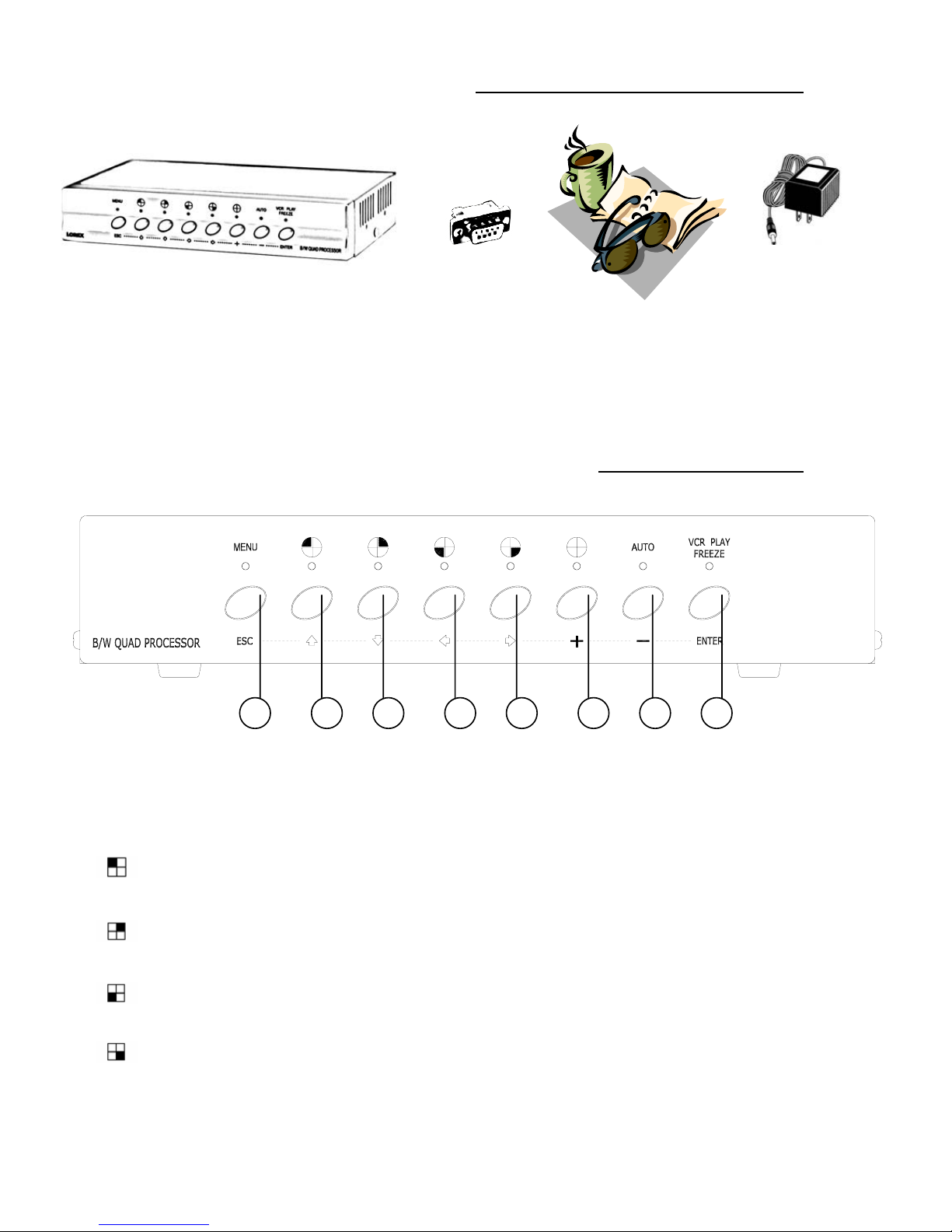
SYSTEM INCLUDES
12V DC Power Supply
B/W Quad Splitter
CHECK YOUR PACKAGE TO MAKE SURE THAT YOU RECEIVED THE COMPLETE SYSTEM, INCLUDING THE COMPONENTS SHOWN ABOVE.
9 Pin Alarm
Connector
Owner’s Manual
FRONT PANEL CONTROLS
1 2 53 4 6 7 8
1.
MENU / ESC
Pressing this button performs the following functions:
1) Accesses the Menu screen;
2) Confirms selections when editing options in Menu mode;
3) Exits the Menu screen.
2.
3.
4.
5.
/ ( ▲ )
Pressing this button goes to Full-Screen display of Camera 1. It also serves as the Up arrow key in Menu mode.
/ ( ▼ )
Pressing this button goes to Full-Screen display of Camera 2. It also serves as the Down arrow key in Menu mode.
/ ( ◄ )
Pressing this button goes to Full-Screen display of Camera 3. It also serves as the Left arrow key in Menu mode.
/ ( ► )
Pressing this button goes to Full-Screen display of Camera 4. It also serves as the Right arrow key in Menu mode.
4
Page 6

6.
QUAD / ( + )
Pressing this button goes to Quad display. It is also used to increase values when making selections in Menu mode.
7.
AUTO / ( - )
Pressing this button initiates automatic sequencing between four all camera locations, in the following screen order:
CH1 Æ CH2 Æ CH3 Æ CH4 Æ QUAD Æ CH1 ……..
Note: Sequencing will automatically bypass a channel with a video loss.
8.
VCR / FREEZE / ENTER
This button performs the following functions:
1) Press and hold this button for 3 seconds in order to enter VCR mode.
2) For the Freeze feature, press this button once. The screen will change to Quad mode, and the word “FREEZE” will
appear in the top-right corner. Press a channel button, and that corresponding channel’s screen will freeze with the
letter “Z” appearing as an indicator. You can then continue to freeze and unfreeze individual channels by pressing
their respective buttons. To exit Freeze mode, press the VCR PLAY / FREEZE / ENTER button a second time.
3) In Menu mode, pressing this button selects a menu option to be edited.
LED INDICATORS
Above each button is a red LED indicator, which shows the system’s status and helps to navigate in Menu mode.
Below is a summary of what each red LED indicator signifies:
1 2 53 4 6 7 8
1) When in Menu mode, this red indicator illuminates.
2-5) When in Full Screen viewing, the LED that is ON is the channel being viewed (CH1 / CH2 / CH3 / CH4).
When in Freeze mode, the LED’s that are ON are the channels being frozen.
In Menu mode, the LED’s that are ON are keys that you need to press in order to navigate through menu options.
During an Alarm or Video Loss, the indicator lights blink on the corresponding channels experiencing the Alarm
or Video Loss.
6) This LED illuminates when in Quad viewing mode.
7) This LED illuminates when in Auto Sequencing mode.
8) This LED illuminates when Freeze mode is activated, or blinks when in VCR mode.
5
Page 7

MENU CONTROLS
Pressing the MENU button brings up the Menu screen.
Outlined below are the buttons used for navigation when using the Menu.
▲and ▼: Scroll up and down through menu options; change values.
◄ and ►: Scroll sideways within a menu option that has been selected
+ and - : Increase or reduce a value of a menu option when editing it (when it is blinking).
ENTER: Selects a submenu / an option in a submenu for browsing / modification
MENU: Completes modification of a menu option; exits a menu
MENU OPTIONS
Upon entering the Menu, you will see the screen shown to
the right. Below is a description of each Menu option:
Alarm Duration
Baud Rate
Dwell Time
Int Audible Alarm
Ext Audible Alarm
Set Time
Dwell Setup
– Set the length of the alarm time between
1~99 seconds.
– Set the speed of the remote computer’s Baud Rate
which is the rate of data transmission. Available
Baud Rates are: 1200, 2400, 3600, 4800, 9600,
19200, 57600, 115200
– Select how long a camera screen will appear in
Sequencing mode before switching to the next
screen. Programmable between 1~30 sec
– Activates / deactivates the alarm buzzer function of the Quad Processor.
– Activates / deactivates the Alarm OUT function for external alarm devices.
– Allows you to program the time.
– Activate / deactivate by channel which cameras will be seen in Auto Sequencing.
( MENU )
►ALARM DURATION: 02 SEC
BAUD RATE: 9600 BPS
DWELL TIME: 02 SEC
INT AUDIBLE ALARM: ON OFF
EXT AUDIBLE ALARM: ON OFF
SET TIME: YY:MM:DD:HH:MM:SS
DWELL SETUP (CH 01): ON OFF
ALARM POLARITY (CH 01): HIGH LOW OFF
CAMERA TITLE SETUP (CH 01): CH1
EVENT LIST
SYSTEM RESET
Alarm Polarity
Note: Leave the Alarm Polarity at LOW or OFF for channels with no PIR Sensor connected.
Camera Title Setup
Event List
System Reset
– Select the Alarm Input for each PIR motion sensor from LOW, HIGH or OFF per channel.
LOW is the equivalent of Normally Open. HIGH is the equivalent of Normally Closed.
OFF disables the PIR Alarm feature. The setting is defaulted to LOW.
Otherwise, you will experience a continuous alarm.
– Change the title for each camera that appears in the On Screen Display.
– Brings up a historical record of Video Loss and Alarm occurrences. For more information on
Video Loss and Alarm, refer to page 8.
– Returns system to factory default settings.
6
Page 8

BACK PANEL
DC 12V
500 mA
G1 G2 G3 G4
1
23
VIDEO INPUT
4
MONITOR ALARM
IN OUT
1 2 53 4 6
1.
POWER INPUT
Connects to the DC 12V Power Adapter.
2.
VIDEO IN (Channels 1-4)
Four BNC Video camera inputs, for Channels 1-4. Connect four B/W cameras to these inputs.
Note: each channel has a knob for adjusting the Gain (contrast and brightness) of the picture.
3.
VCR IN
Receives video from a VCR or DVR.
4.
MONITOR OUT
Transmits video to a slave monitor (a TV or a security monitor).
QUADVCR
OUT
5.
QUAD OUT
Transmits video to a VCR or DVR.
6.
RS232 / ALARM INPUT / EXTERNAL I/O
Connects to an Alarm Block, which accommodates PIR Motion Sensor connection and enables Alarms.
Alternatively, this output can serve as a Remote Protocol for control via a PC.
7
Page 9

ALARM AND VIDEO LOSS
When an Alarm occurs, you will see the icon appear on the channel where motion detection is taking
place. If you have set the Internal Audible Alarm to ON, then you will also hear a Buzzer.
A Channel that does not have a camera connected will show the icon,
indicating a Video Loss. The red LED light above the channel with a Video Loss
will blink. If you have set the Internal Audible Alarm to ON, then you will also
hear a Buzzer when video is disconnected.
The Event List, available from the Menu and shown to the right, lists occurrences
of Alarms and Video Loss.
CH EVENT YY/MM/DD TIME
----------------------------CH1 VLOSS 01/02/10 12:20:15
CH2 ALARM 02/01/15 22:10:25
--- ----- --/--/-- --:--:--
--- ----- --/--/-- --:--:--
--- ----- --/--/-- --:--:--
--- ----- --/--/-- --:--:--
RS232 REMOTE PROTOCOL
The RS232 / Alarm input allows you to control the Quad Processor system from your PC. In order to
achieve this, you will require an RS232 COM Port communication program installed on your PC. There are
many of these software programs available on the internet, some of which are free.
The remote connection on the Quad Processor uses 8 data bits, 1 start bit, and 1 stop bit.
Below is an example of the data stream with the control codes shown.
ACT – OxFF
The PC keyboard simulates the Quad Processor’s keypad. For example, pressing “V” will make the Quad
Processor go to VCR mode. Note that the letters are case sensitive. Below is a list of corresponding keys,
and their codes:
ASCII
A
Q
M
V
F
For further instructions on connecting the Quad Processor to your PC’s RS232 port, please refer to
Appendix #4.
OxCO ID
FUNCTION
AUTO
QUAD
MENU
VCR
FREEZE
ASCII
1
2
3
4
FUNCTION STOP – Ox7F
FUNCTION
CH1
CH2
CH3
CH4
8
Page 10

TROUBLESHOOTING
REMEDYPROBLEM
Unable to view cameras
No Power
Continuous Alarm
Bad picture quality after Power ON
• If you are using a TV as a slave monitor, you may need
to set the channel as AUX (or sometimes referred to as
“TV / Video”).
• Please check if the wiring between the monitor and the
Quad Processor is correct.
• Make sure that the camera is receiving power
• Check the power source cord connections
• Check that there is power at the outlet
• Set the Alarm Polarity according to whether your PIR
motion sensor is Normally Open or Normally Closed.
• If no motion sensors are connected, set that channel’s
Alarm Polarity to OFF.
• Connect the video cable on Channel 1 before Power
ON. The system will automatically detect electrical
settings as PAL or NTSC.
TECHNICAL SPECIFICATIONS
Video input port 4 BNC camera inputs, 1 VCR input
Video output port 1 Quad output for VCR, 1 monitor output
Alarm input 4
Alarm output 1
Alarm duration 1 – 99 sec.
Camera Title 10 characters
Time / Date set Built-in real time clock
Dwell Time 1 – 30 sec.
RS-232 port Yes
Load impedance 75 Ohms
Operating environment 10~80%RH, 0oC~50oC
Power source
Power consumption 6W maximum
Dimension (mm) 240(W) x 45 (H) x 150 (D)
Weight 1,300g
DC 12V ± 10%, 500mA
Because our products are subject to continuous improvement SVC reserves the right to modify product designs and specifications without notice and without incurring any obligations. E & O.E
9
Page 11

OPTIONAL ACCESSORIES
The following accessories are available to add to your existing system.
DIGITAL VIDEO RECORDER
Record images digitally to a
hard-disk drive. Record up to
1850 hours (30 hours real time).
Use the Quick Search feature
to find specific recordings.
SUNSHADE HOUSING
TIME LAPSE VCR
Used to record key events.
Select From a 40 hour real
time or 960 Hour time lapse
VCR
AUTO PAN
NIGHTVISION
Weatherproof Night vision
accessory. Allows you to
see in the dark up to 35-40
distance (for use with
Observation system
cameras)
SPECIALTY CAMERAS
Protects observation
camera From the sun
Rotates camera up to 270°
Select from a wide
assortment Of specialty
cameras (dome,
Weatherproof, bullet,
Waterproof, etc.) to suit
Individual needs
TO ORDER THESE ACCESSORY ITEMS OR FOR A COMPLETE LINE OF ACCESSORIES
www.lorexcctv.com
10
Page 12

APPENDIX #1 – TYPICAL CONFIGURATION
DC 12V
500 mA
1
23
VIDEO INPUT
4
MONITOR ALARM
IN OUT
QUADVCR
OUT
THE B&W QUAD HAS BNC JACKS TO CONNECT TO OTHER VIDEO SOURCES. BNC
COUPLERS AND VIDEO CABLES ARE NOT INCLUDED.
Note: If using a TV as a slave monitor, it may have to be set in AUX mode (sometimes referred to as TV/Video)
11
Page 13

APPENDIX #2 – ALARM BLOCK CONNECTION
to PIR MOTION SENSOR
Wires from the PIR Motion Sensors must be soldered to the contacts of the 9 Pin Alarm Connector.
Each PIR Sensor connects via 2 wires: 1 to a specific Channel and the other to the Ground input.
For descriptions of each contact on the 9 Pin Connector of the Quad Processor, please refer to Appendix #4.
PIR Motion Sensors
9 PIN Alarm Connector
7
8
2
3
12
Page 14

APPENDIX #3 – CONNECTION to a LOREX
TIME LAPSE VCR FOR ALARM RECORDING
Wires being run from the Time Lapse VCR’s or DVR’s alarm terminal must be soldered to the appropriate
contacts of the 9 Pin Alarm Connector.
In addition to connecting up to 4 PIR Motion Sensors, connect the 9 Pin Alarm Connector to a security recorder
such as the Lorex Time Lapse VCR shown below for Alarm Recording upon motion detection.
For descriptions of each contact on the 9 Pin Connector of the Quad Processor, please refer to Appendix #4.
4 5
MONITOR ALARM
IN OUT
QUADVCR
OUT
13
Page 15

APPENDIX #4 – PIN CONFIGURATIONS
FOR CONNECTION TO A COMPUTER
25 PIN COM PORT
9 PIN COM PORT
14
 Loading...