

Page 1
Model SG8100
Ú >
Before operating this unit, please read manual thoroughly
Ù 3
OPERATING INSTRUCTIONS
99--CHANNEL MULTIVIEW
CHANNEL MULTIVIEW
Page 2
Before using this product, please follow the safety guidelines listed below:
Ú >
This unit is designed for indoor use. To prevent electrical shock injury, and fire
hazard, please do not place this product outdoors, or in the rain, or in humid
surroundings such as in a bathroom, laundry room, basement, or near a pool area.
Ú >
Do not attempt to service this unit by disassembling the cabinet This may
expose you to dangerous voltage and other hazards. Refer all servicing to a
qualified service center or return to provided.
Ú >
Should any liquid or solid object fall into the cabinet, or if you notice an unusual
smell or smoke during operation, turn off the power and unplug the unit
immediately. Have the unit checked by a qualified technician before further
operation. Continued use without proper servicing may result in electrical
shock and fire hazard.
Ú >
Use and connect only the accessories supplied for the unit. Do not use any other
unauthorized accessories.
Ú >
If the cabinet is cracked or produces noise due to negligence or mishandling, turn
power off and unplug the unit. Contact local qualified service center, or
manufacturer as soon as possible.
Ùp
NOTE
Ú J
1.
This equipment has been certified and found to comply with the limits
regulated by FCC,
EMC and LVD.
Therefore, it is designed to provide
reasonable protection against interference and will not cause interference
with other appliance usage. However, it is imperative that user follows this
manual's guidelines to avoid improper usage which may result in damage to
the unit, electrical shock and fire hazard or injury.
2.
In order to improve the feature functions and quality of this product, the
specifications are subject to change without notice from time to time.
1
Note: Please follow the safety guidelines. For any further
safety questions about this unit, please contact
manufacturer or a qualified service center.
Ú 1
SAFETY
1
Ú >
Video Input
Level............................................…....... 1V p-p (into 75
Connector...................................….......... BNC
2
Ú >
Audio Input
Level...................................................... 1V p-p (into 600
Connector................................................. RCA JACK
3
Ú >
Video Output
Level......................................................… 1V p-p (into 75
Connector...............................................… RCA JACK
4
Ú >
Audio Output
Level......................................................... 1V p-p (into 600
Connector................................................. RCA JACK
5
Ú >
Sensor Input ...........................................… N.C. (Normally closed)
6
Ú >
Alarm output 1, output 2 .......................... NO.(Normally open)
7. DC power Input.......................................... DC 12V 1.5A
8. DC power output........................................ DC 12V +
8-2. SPECIFICATIONS
Page 3

TABLE OF CONTENTS
1. Product Introduction..........................................................................… 3
2. Unpacking the unit............................................................................… 4
3. Basic operations and controls.............................................................…5
3-1. Location and function of controls............................................ 5
3-2. Key Functions on the Remote................................................. 7
4. Setting up and operating procedures.................................................…9
4-1. Connecting the cables............................…............................. 9
4-2. Setting up the home security with alarm system......................10
5. Channel Auto-sequencing ..............................................................… 14
6. Alarm trigger...............................................................................….... 15
7. Troubleshooting..........................................................................….... 16
8. General feature and specifications..................................................… 17
8-1. General feature....................................................................…17
8-2. Specifications......................................................................…18
CHAPTER PAGE
Page 4

1. Product Introduction
The LOREX MULTIVIEW has the ability to divide and display pictures on
a CCTV monitor. It can be connected to up to 9 security cameras. This
unit is able to provide various types of picture compositions. Through
operation from the remote control, the user is able to select the number of
pictures to appear on the screen. The picture composition can be selected
from one to up to 9 different pictures on the same screen.
Dividing the pictures on the same screen is one of the most basic functions
the MULTIVIEW has to offer. Another distinguishing feature is that it can
be connected to any
CCD
camera in conjunction with any sensor (i.e.,
frequency or infrared sensor) to become an easy to use home security
system with complete security functions. When a sensor, if used, senses any
intrusion, the picture window will appear on your screen and an alarm with
a beeping sound will alert the viewer.
In addition to the above two outstanding features the MULTIVIEW also has
a built-in clock for user set up of time/date.
Additional Features:
You can also connect other A/V equipment (such as a DVD or camcorder)
to your LOREX Multiview. You will need an RCA/BNC coupler (not
included) for each device you wish to connect.
3
7. Trouble shooting
Before operating the unit, please read this manual thoroughly. If you
encounter problems with your unit, go through the check list below.
Symptom Cause and Remedy
Power light is not on
No picture or sound
Remote control does not
operate
NOTE
Should any problem persist after you have made these checks,
consult qualified service personnel. Do not attempt to
open unit. Electrical shock or injury could result.
Page 5
415
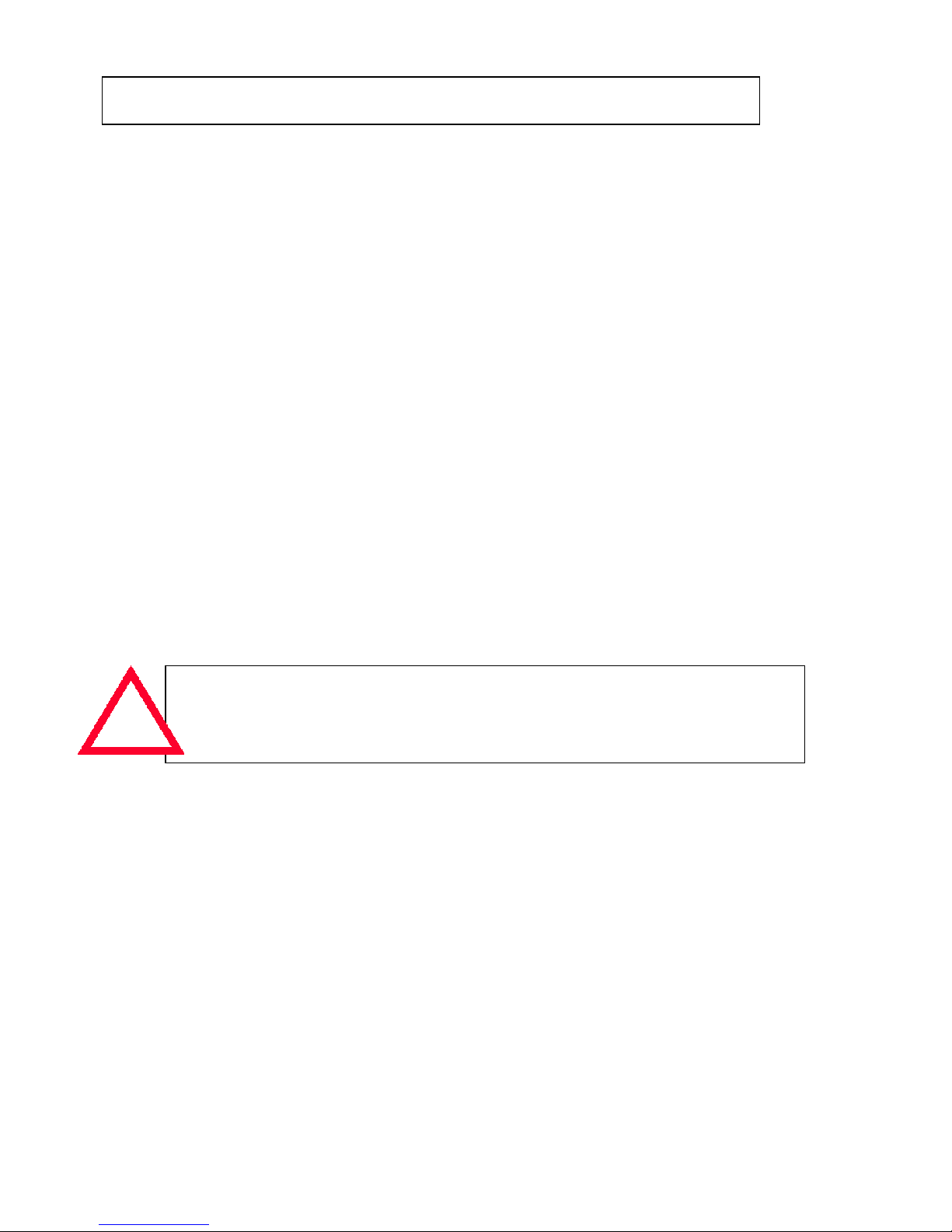
The unit carton contains the following items. If any of these items are missing,
please contact the dealer from whom you purchased the unit for prompt
replacement or call Pro-Video.
1. MULTIVIEW SYSTEM…………… 1
with 9 A/V inputs and VCR IN
1 A/V output to VCR
1 A/V output to TV
2. Remote Control…………………………1
with 2 size AA Alkaline Batteries
3.RCA two-color A/V cable………………1
4.ADAPTER …………………………… 1
AC 120V IN/ O/P : 12V 1.5A
OR
AC 230V IN/ O/P : 12V 1.5A
2. Unpacking the unit6. Alarm trigger
Page 6
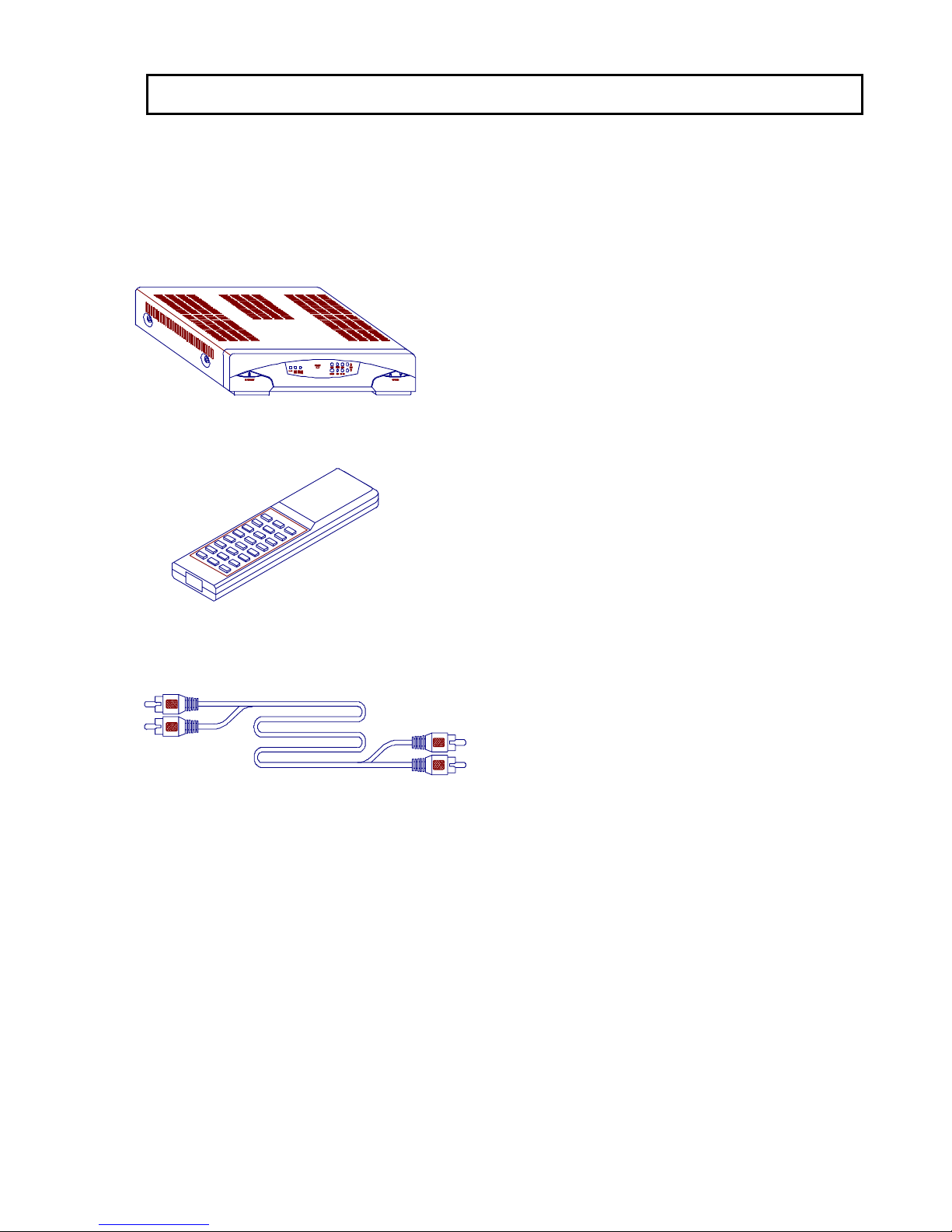
3-1. Location and function of controls
5
3. Basic operations and controls
Ùp
Front Panel
1
2
3
4 12
10
11
14
6
5
7
8
9
13
1. ON/STANDBY : Power on mode (running) or standby mode.
2. AL RS : Alarm Reset-Resets Multiview to normal state.
3. LIVE/TAPE : Select video source from either normal video input
(LIVE) or VCR tape.
4. BELL MUTE & PANIC(2) :
BELL MUTE : Turns buzzer sound off in case of alarm
PANIC (2) : In an emergency, press the key twice to trigger all alarms & sensors.
5. IRR : Remote control sensor.
6. POWER : Power light indicator.
7. SEQ : Turns auto-sequence mode ON/OFF.
8. PROG : Channel programming.
9. MENU : Starts menu dialog session.
10. ENTER : Data entry key.
11. EXIT : Exit menu dialog.
12. PIP ON : Turns PIP window display ON/OFF.
13. CH: Main channel up/down key.
14. SUB : SUB channel up/down key.
5. Channel Auto-sequencing
(1) Automatic video sequencing is only valid when the screen is displayed in SINGLE
and TWIN mode. The incoming videos are displayed in real time when user enables
automatic sequence by pressing <seq> button.
The automatic sequence logic begins to switch videos in sequence.
(2) When <seq> key is pressed, SEQ wording displays on the lower right corner of the
screen. Press any key except LIVE/TAPE & Program key to cancel SEQ function.
NOTE
Note:Fora detailed description offunction keys,please referto P7 & P8.
(8) Press key number 8 , the screen will display the following text.
Use CH <up> and <down> to change the number between 0-23.
Then press . The cursor will move to the first digit of the
Minute-field.
Use CH <up> and <down> to change the number between 0 and 5.
Then press . The cursor will move to the last digit of the
Minute-field.
Use CH <up> and <down> to change the number between 0 and 9.
Then press . The cursor will move to next field.
Use CH <up> and <down> to change the day.
Press . The cursor will move to next field.
Use CH <up> and <down> to change the month.
Press . The cursor will move to next field.
Use CH <up> and <down> to change the year.
Press . The cursor will move to next field.
Use CH <up> and <down> to switch ON/OFF
Press to return normal screen display.
N ote:aftera pow erfailure,the tim e/date screen willblink “00:00”(hh:m m )You will
need to re-enterthe new tim e/date.
FO R PAL/EUR O PEAN SYSTEM S:
Page 7

6
Ùp
Rear Panel
1
4
7
6
5
2
3
1. 9 A/V INPUT (BNC connector for video and RCA connectors for
mono audio)
2. VCR Loop terminal
3. A/V output : 1. For VCR recording
2. For TV input
4. 12V/500mA DC generally for CCD camera power.
5. Sensor input terminal (normally closed)
6. Dry contact output, activated in case of alarm triggered.
7. DC power inlet.
Page 8

7
(1)
……Power on/off
(2)
……Gives you a list of options
from which to choose.
(3)
……Numeric buttons
Ú J
1.
Select equipment to be
operated
2.
Select the page number for
the particular picture mode
(4)
……This key brings up both the
main and window pictures
simultaneously on the screen.
Window picture appears on the
right top corner of the screen.
(5)
……Press this key after each selected
choice from the
MENU
.
(6)
Ù 1
……
UP/DOWN
key allows for
selections on main screen.
(7)
……This
UP/DOWN
key allows for
selections on the window screen.
(PIP)
(8)
…… Press this button will toggle
ON/OFF of auto-sequence mode.
3-2. Key Functions on the Remote
POWER
MENU
1
9
PIP ON
ENTER
~
SEQ
SUB
CH
(7)
(6)
(5)
(4)
(3)
(1)
(8)
(2)
(6) Press key number 6, screen displays a picture
illustrated on the right.
Press CH <up> and <down> keys to move the
flashing cursor. Moving sequence:
ch1-off-ch2-off-ch3-off.
Press SUB <up> and <down> keys to change
row 2, the value alters among channels 1-9.
Press SUB <up> and <down> keys to change
row 3, the display switches between on/off.
This menu is to set up the correspondence between sensor and input
video channels.
For example:
When sensor #2 is triggered, the main window immediately displays
the video of channel 3.
(7) Press key number 7, the screen prompt the following text
Two values (time of sequencer dwell and alarm dwell) are left to setup.
The value is adjustable. Use CH <up> and <down> keys to select items
between SEQ DWELL and ALR DWELL. Use SUB <up> and <down>
keys to alter item value. Each value can be selected from 3-15-30-40-60
press key to quit this operation.
EXIT
Page 9

8
(9)
……Pressing this button will enable
the system to start detecting every video channel
for one cycle. A video channel with valid signal
input is marked as ‘activated’, whereas a video
channel with no signal input is marked as ‘idle’.
In normal operation, an idle channel is shown in
blue.
(10)
……’Live’ indicates the normal
video coming from 9 input terminals. “TAPE”
indicates the video coming from the VCR Loop
terminal. The key is used to switch the videos
between normal input and VCR Loop.
(11)
……(1) In an alarm
( i.e.. any of PIR has been triggered) Multiview
will start beeping. Press this key to turn
the buzzer sound off. (2) In normal case ( no
PIR has been triggered) Click this key twice
to set Multiview in panic mode,( both the
buzzer and output are turned on and the
VCR starts recording.
Note
: the two clicks should not be longer than
1.5 sec apart.
(12)
……Alarm Reset
Press this twice within 1.5 sec to reset
Multiview to normal, ( resumes screen display
and stops VCR recording )
(13)
……Terminates the present selected
choice and returns to the first choice.
PROG
LIVE/TAPE
BELL MT & PANIC(2
)
AL RS
EXIT
(11)
(9)
3-2. Key Functions on the Remote (Cont’d)
(13)
(12)
(10)
Page 10

Operating Multiview
When key is pressed, screen displays the picture
illustrated on the right.
Press CH <up> and <down> keys to select 1-8 for
function or setting.
Functions 1-8 can also be accessed by pressing the
numbers 1-8 directly.
(1) Press key number 1, screen displays a full screen
size picture as illustrated on the right.
Press CH <up> and <down> keys to select
channels 1-8.
(2) Press key number 2, screen displays a split picture
as illustrated on the right. Press CH <up> and
<down> keys to select (MAIN) picture’s
channels 1-8. Press SUB <up> and <down>
keys to select (SUB) picture’s channels 1-8.
9
4-1
.
Connecting the cables
4. Setting up and operating procedures
TV
VCR
CCD
CCD
CCD
SIR EN
power
Trigger SIREN
AC Adapter
VCR
VCR out
To VCR
To TV
CCD
camera
CCD
camera
CCD
camera
PIR
Note: (1) To change settings, press Key to re-scan channels and to
re-set active/idle channels.
(2) When sensor is not triggered in an event of emergency, press
key twice successively to activate Multiview’s
internal buzzer, output 1, and output 2.
Press key twice to cancel the activation.
(3) When using a DC 12V output, be sure not to exceed 500mAmp or
the operation of the Multiview may be affected.
4-2. Setting up the home security with alarm system
MENU
PROG
AL RS
PANIC(2)
Trigger VCR
Page 11

10
Operating Multiview
When key is pressed, screen displays the picture
illustrated on the right.
Press CH <up> and <down> keys to select 1-8 for
function or setting.
Functions 1-8 can also be accessed by pressing the
numbers 1-8 directly.
(1) Press key number 1, screen displays a full screen
size picture as illustrated on the right.
Press CH <up> and <down> keys to select
channels 1-8.
(2) Press key number 2, screen displays a split picture
as illustrated on the right. Press CH <up> and
<down> keys to select (MAIN) picture’s
channels 1-8. Press SUB <up> and <down>
keys to select (SUB) picture’s channels 1-8.
4-2. Setting up the home security with alarm system
1. SINGLE
2. TWIN
3. MULTI-PICTURE 4
4. MULTI-PICTURE 6
5. MULTI-PICTURE 9
6. SECURITY
7. DWELL
8. TIME/DATE
CH1
(
main
)
CH1
(MAIN)
CH2
(SUB)
MENU
Page 12

11
(3) Press key number 3, screen displays a picture
illustrated on the right. Press CH <up> and
<down> keys to select (MAIN) picture’s
channels 1-9. MAIN channel is displayed in
real time. Press SUB <up> and <down> keys
to select (SUB) picture’s channels. SUB 1-3
channels are displayed in auto sequence cycle.
(4) Press key number 4, screen displays a picture
illustrated on the right. Press CH <up> and
<down> keys to select (MAIN) picture’s
channels 1-9. MAIN channel is displayed in
real time. Press SUB <up> and <down> keys
to select (SUB) picture’s channels. SUB 1-5
channels are displayed in auto sequence cycle.
(5) Press key number 5, screen displays a picture
illustrated on the right. Press CH <up> and
<down> keys to select (MAIN) picture’s
channels 1-9. MAIN channel is displayed in
real time. MAIN and SUB 1-8 channels are
displayed in auto sequence cycle.
(9)
……Pressing this button will enable
the system to start detecting every video channel
for one cycle. A video channel with valid signal
input is marked as ‘activated’, whereas a video
channel with no signal input is marked as ‘idle’.
In normal operation, an idle channel is shown in
blue.
(10)
video coming from 9 input terminals. “TAPE”
indicates the video coming from the VCR Loop
terminal. The key is used to switch the videos
between normal input and VCR Loop.
(11)
( i.e.. any of PIR has been triggered) Multiview
will start beeping. Press this key to turn
the buzzer sound off. (2) In normal case ( no
PIR has been triggered) Click this key twice
to set Multiview in panic mode,( both the
buzzer and output are turned on and the
VCR starts recording.
Note
: the two clicks should not be longer than
1.5 sec apart.
(12)
Press this twice within 1.5 sec to reset
Multiview to normal, ( resumes screen display
and stops VCR recording )
(13)
……Terminates the present selected
choice and returns to the first choice.
PROG
LIVE/TAPE
BELL MT & PANIC(2
AL RS
EXIT
3-2. Key Functions on the Remote (Cont’d)
CH2
(SUB1)
CH4
(SUB3)
CH3
(SUB2)
CH1
(MAIN)
CH1
(main)
CH4
SUB3
CH5
SUB4
CH6
SUB5
CH3
SUB2
CH2
SUB1
CH1 CH2 CH3
(MAIN) SUB1 SUB2
CH4 CH5 CH6
SUB3 SUB4 SUB5
CH7 CH8 CH9
SUB6 SUB7 SUB8
N ote:1)In realtim e m ode (S ingle orTwin M ode ),when the video source is lost,
the m ain channelscreen w illturn red,and the sub channelw illturn Blue
2)In M ulti-M ode (4/6/9 M ode ),w hen the video source is lost,the m ain
channelscreen willturn red,and the sub channelw illturn black.
Page 13

12
SENSOR1 CH1 OFF
SENSOR2 CH2 OFF
SENSOR3 CH3 OFF
(6) Press key number 6, screen displays a picture
illustrated on the right.
Press CH <up> and <down> keys to move the
flashing cursor. Moving sequence:
ch1-off-ch2-off-ch3-off.
Press SUB <up> and <down> keys to change
row 2, the value alters among channels 1-9.
Press SUB <up> and <down> keys to change
row 3, the display switches between on/off.
This menu is to set up the correspondence between sensor and input
video channels.
For example:
SENSOR 2 CH3 ON
When sensor #2 is triggered, the main window immediately displays
the video of channel 3.
(7) Press key number 7, the screen prompt the following text
SEQ DWELL 15
ALR DWELL 15
Two values (time of sequencer dwell and alarm dwell) are left to setup.
The value is adjustable. Use CH <up> and <down> keys to select items
between SEQ DWELL and ALR DWELL. Use SUB <up> and <down>
keys to alter item value. Each value can be selected from 3-15-30-40-60
press key to quit this operation.
EXIT
Page 14

13
Ùp
Rear Panel
1. 9 A/V INPUT (BNC connector for video and RCA connectors for
mono audio)
2. VCR Loop terminal
3. A/V output : 1. For VCR recording
4. 12V/500mA DC generally for CCD camera power.
5. Sensor input terminal (normally closed)
6. Dry contact output, activated in case of alarm triggered.
7. DC power inlet.
AM hh:mm ON/OFF
MM:DD:YY
(8) Press key number 8, the screen will prompt the following text.
Press CH <up> and <down> to toggle between AM/PM.
Then press . The cursor will move to Hour-field.
Use CH <up> and <down> to change the value between 0-12.
Then press . The cursor will move to the first digit of
Minute-field.
Use CH <up> and <down> to change the value between 0 and 5.
Then press . The cursor will move to the last digit of
Minute-field.
Use CH <up> and <down> to change the value between 0 and 9.
Then press . The cursor will move to next field.
Use CH <up> and <down> to change the value of Day.
Press . The cursor will move to next field.
Use CH <up> and <down> to change the value of Month.
Press . The cursor will move to next field.
Use CH <up> and <down> to change the value of year.
Press . The cursor will move to next field.
Use CH <up> and <down> to switch ON/OFF the display of
Press to return normal screen display.
hh:Hour
mm:Minutes
YY:Year
MM:Month
DD:Day
ENTER
ENTER
ENTER
ENTER
ENTER
ENTER
EXIT
ENTER
N ote:aftera pow erfailure,the tim e/date screen w illblink “00:00”(hh:m m ).You
w illneed to re-enterthe new tim e/date.
(N orth Am erican)
FO R N TSE/NO RTH AM ER IC AN SYSTEM S:
Page 15

14
5. Channel Auto-sequencing
(1) Automatic video sequencing is only valid when the screen is displayed in SINGLE
and TWIN mode. The incoming videos are displayed in real time when user enables
automatic sequence by pressing <seq> button.
The automatic sequence logic begins to switch videos in sequence.
(2) When <seq> key is pressed, SEQ wording displays on the lower right corner of the
screen. Press any key except LIVE/TAPE & Program key to cancel SEQ function.
13
hh:mm ON/OFF
DD:MM:YY
(8) Press key number 8 , the screen will display the following text.
Use CH <up> and <down> to change the number between 0-23.
Then press . The cursor will move to the first digit of the
Minute-field.
Use CH <up> and <down> to change the number between 0 and 5.
Then press . The cursor will move to the last digit of the
Minute-field.
Use CH <up> and <down> to change the number between 0 and 9.
Then press . The cursor will move to next field.
Use CH <up> and <down> to change the day.
Press . The cursor will move to next field.
Use CH <up> and <down> to change the month.
Press . The cursor will move to next field.
Use CH <up> and <down> to change the year.
Press . The cursor will move to next field.
Use CH <up> and <down> to switch ON/OFF
Press to return normal screen display.
hh:Hour
mm:Minutes
YY:Year
MM:Month
DD:Day
ENTER
ENTER
ENTER
ENTER
EXIT
ENTER
N ote:aftera pow erfailure,the tim e/date screen w illblink “00:00”(hh:m m )You w ill
need to re-enterthe new tim e/date.
(European system )
ENTER
FO R PAL/EUR O PEAN SYSTEM S:
Page 16

The unit carton contains the following items. If any of these items are missing,
please contact the dealer from whom you purchased the unit for prompt
replacement or call Pro-Video.
2. Unpacking the unit6. Alarm trigger
When any sensor is triggered:
(1) Multiview’s internal buzzer is activated.
(2) Output 1 (NO and NC) is activated and triggers siren or light.
(3) Output 2 (NO and NC) is activated and triggers VCR to be ON.
For example : SENSOR 1 CH2 ON
SENSOR 2 CH3 ON
SENSOR 3 CH1 ON
a. If screen is displayed in 4/6/9 mode, in an event of sensor #2 being
triggered, screen changes display to SINGLE MODE picture.
If sensor #1 is triggered following sensor #2, then the screen changes
display to TWIN MODE picture. If sensor #3 is triggered following
sensor #1 and #2, then sensor #1 picture displays on the <main> window,
sensors #2 and #3 pictures display on the <sub> windows. The <sub>
windows auto switch every 3 seconds.
If all 3 sensors are activated, when AL DWELL time setting is less than
15 seconds, AL DWELL would be set at 15 seconds.
When AL DWELL is over, 4/6/9 mode returns.
b. If screen is displayed in Single/Twin mode, when AL DWELL
is over, screen returns to Single Mode.
(4) When sensor is triggered, date/time automatically displays on the screen.
(5) When trigger is activated, <BELL MT> can be pressed to turn off
Multiview’s internal buzzer.
(6) When trigger is activated, <AL RS> key can be pressed twice to turn off
Mutiview's internal buzzer, output 1, and output 2.
(7) When in 4/6/9 multi-picture mode, press the channel number key directly
to access the matching channel’s picture which appears in Single mode
automatically for observation. Press the same number key to return to
4/6/9 multi-picture mode.
Page 17

16
7. Trouble shooting
Before operating the unit, please read this manual thoroughly. If you
encounter problems with your unit, go through the check list below.
Symptom Cause and Remedy
Power light is not on
No picture or sound
Remote control does not
operate
Make sure power cord is connected
to an D.C. INLET.
Check that all CCD equipments’
power is switched ON.
Check if all cable is connected
correctly and securely
Make sure batteries are installed
properly
Test battery condition
NOTE
Should any problem persist after you have made these checks,
consult qualified service personnel. Do not attempt to
open unit. Electrical shock or injury could result.
Page 18

Design and specifications subject to
change without notice.
Ú >
Before operating this unit, please read manual thoroughly
OPERATING INSTRUCTIONS
99--CHANNEL MULTIVIEW
CHANNEL MULTIVIEW
 Loading...