

Page 1
Product Information
User Manuals
Quick Start Guides
Specification Sheets
Software Upgrades
Firmware Upgrades
VISIT
www.lorexcctv.com
QUICK START GUIDE
www.lorexcctv.com
Lorex Technologies Inc.
Copyright © 2009 Lorex Technologies Inc.
As our products are subject to continuous
improvement, Lorex reserves the right to
modify product design, specifications and
prices, without notice and without incurring
any obligation. E&OE
IT’S ALL ON THE WEB!
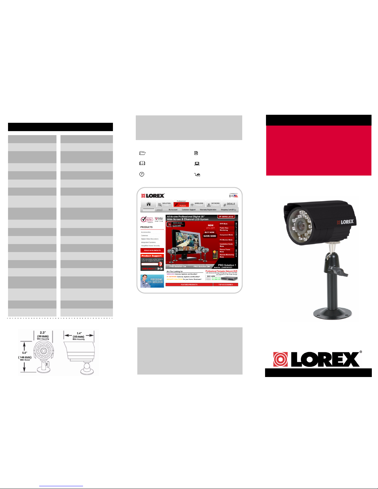
Camera Specifications
HIGH RESOLUTION
WEATHERPROOF
COLOR CAMERA
WITH NIGHT VISION AND AUDIO
Dimensions:
Image Device 1/4” Color Image Sensor
Effective Pixels 656H x 492V
Scanning System
Resolution
AES Shutter Speed
S/N Ratio
Sync. System
Min. Illumination
White Balance
Video Output
Lens
Power Requirement
Power Consumption
Operating Temp
Operating Humidity
2:1 Interlace
NTSC: 525 Lines
Horizontal 450 TV lines
1/60 ~ 1/50,000 sec.
More than 48dB (AGC off)
Internal
3 LUX @F1.2 (no LED)
0 LUX (with LED)
AWB
1.0 Vp-p (75 ohms)
Fixed lens (3.6 mm)
DC 12V ± 10%
With IR: Max 280mA
w/o IR: Max 90mA
14°F ~ 122°F
(-10
°~ 50°C)
Within 90% RH
Viewing Angle H: 59°; V:44°; D: 73°
IR Night Vision 18 IR LED / 850 nm / 50’
(15 m)
Termination 6-Pin DIN
FOV (Diagonal) 73 Degrees
Weight (With Stand) 0.60 lb / 0.27 kg
MODEL: SG7540B
English Version 1.0
Page 2
1. Mount the camera stand to the desired mounting
surface. Attach the camera to the supplied stand.
NOTE:
The camera can be mounted to either a wall or
a ceiling.
2. Aim the camera. Remove
the protective film from
the lens.
3. Connect the extension
cable to the camera.
Connect the other end of
the extension cable to the system.
NOTE:
Confirm that the arrows on the DIN extension
cable are aligned with the camera cable and system
ports when connecting the cable. If the pins in the DIN
connectors are bent, the camera will NOT function.
NOTE: Make sure the DIN connectors are firmly
connected and flush. A tight seal ensures
weatherproofing of the cable connectors.
ATTENTION: Test the camera prior to selecting a permanent
mounting location by temporarily connecting the cameras and
cables to the system.
Figure 1.0 Attach the camera to the mounting stand
Wall Mount
Ceiling Mount
Figure 2.0 Remove film
Figure 3.0 Connect the extension cable
Figure 4.0 Firmly connect DIN connectors
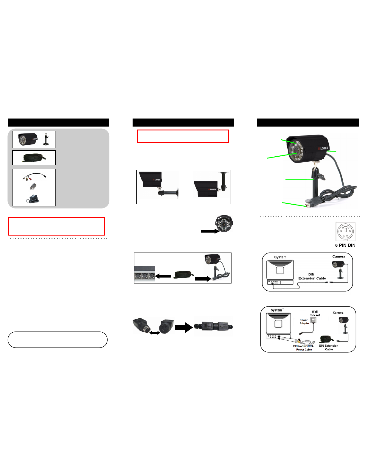
Package Contents Installing the Camera Camera Diagram
1 x Camera
1 x Camera stand
6-PIN DIN Connection:
Lorex cameras with 6-Pin DIN
connections draw power from the system.
Additional power adapters are not needed
for these cameras when connected to a
DIN port on a Lorex system.
DIN-to-BNC Connection Diagram:
‡To connect to a TV, use the included BNC-to-RCA adapter.
Video IN
Audio IN
Infrared LEDs
Lens
Microphone
Adjustable stand
DIN connector
*Included with the SG7540B single pack only. This provides universal
compatibility with industry standard BNC and RCA ports.
Features:
• High Resolution Image Sensor
• IR Cut Filter provides accurate color reproduction in all
lighting conditions
• 18 High Intensity IR LEDs provide effective night vision
range up to 50 ft. (15 m)**
• Day/Night mode: Picture automatically switches to
B&W delivering better clarity in low light conditions
• Built-in microphone provides one-way audio from the
camera to the system
• Weatherproof cameras and cables ideal for indoor and
outdoor applications (IP66)
†
• All-in-one camera cable (audio, video, and power)
plugs directly to Lorex systems with DIN ports and
eliminates the need for a separate power adapter
• 60 ft. (18 m) extension cable included per camera
• Ceiling or wall mountable camera with versatile stand
provides flexible mounting options
** Night vision range up to 50 ft. (15 m) in ideal conditions. Objects at or
beyond this range may be partially or completely obscured, depending on the
camera application.
†Not recommended for submersion in water.
WARNING: Regulated 12V DC 500mA power supply is
REQUIRED for use with this camera, when connected to a BNC
system. Use of a non-regulated, non-conforming power supply can
damage this product and will void the warranty.
NOTE: This camera includes a mechanical Auto IR Cut Filter. When
the camera changes between Day/Night lighting, an audible clicking
noise may be heard from the camera. This clicking is normal, and
indicates the camera filter is working.
Figure 5.0 Camera diagram
1 x 60’ (18 m) DIN
Extension cable
1 x DIN-to-BNC/RCA/
Power cable
1 x BNC-to-RCA Adapter
1 x Power adapter
*
*
*
 Loading...