

Page 1
OPERATING INSTRUCTIONS
Before operating the unit, please read this manual thoroughly
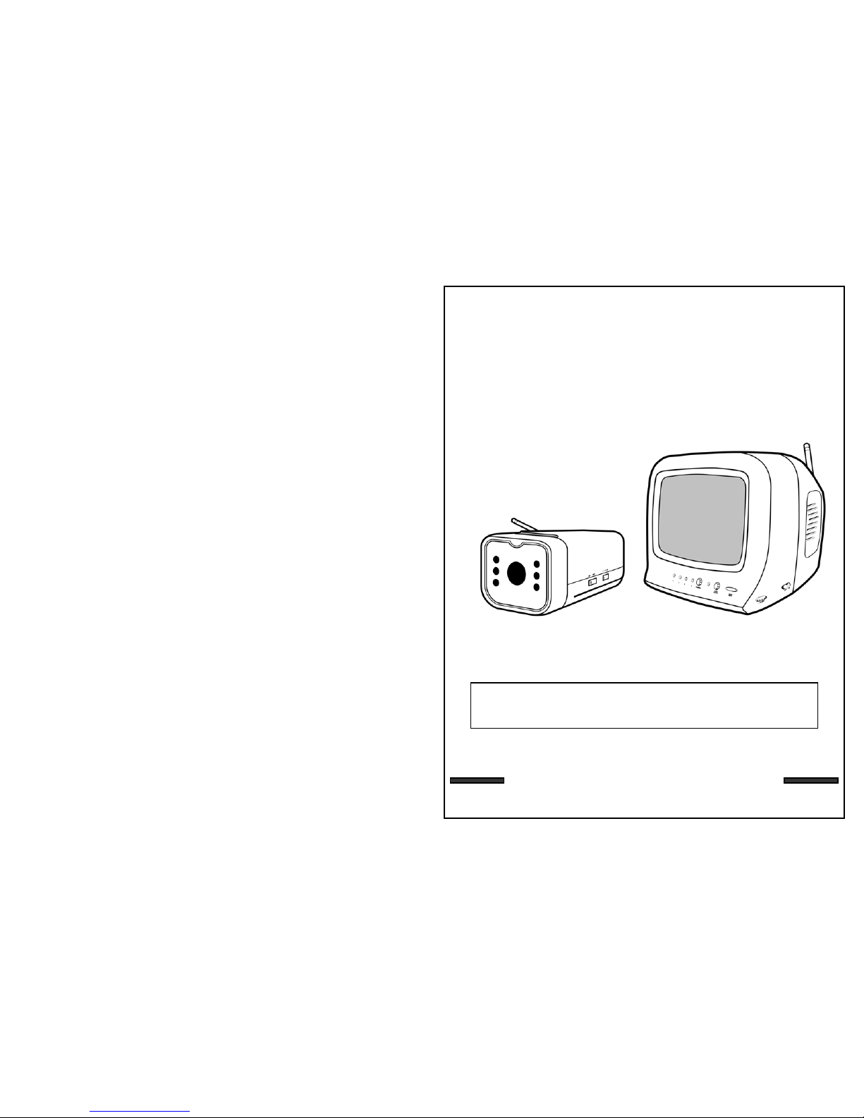
2.4 GHz WIRELESS
VIDEO SECURITY SYSTEM
Rev 03/01-1
This product broadcasts over public airwaves and its
video and audio signals may be intercepted without your
consent.
Page 2

SPECIFICATIONS
WIRELESS CAMERA
Image sensor
Lens
Picture Elements
Scanning system
Scanning frequency
Sync. system
Resolution
Min. illuminations
Video Output
Gamma characteristics
Auto Iris
Microphone
Transmitting frequency
Modulation
RF out level
Video Output level
Antenna
Operating temperature
Power source
Dimensions (without battery
compartment)
Battery Life
Weight
Battery Box
CMOS
3.6mm
510 x 492 (Color), 320X240 (B&W)
2:1 interlace
15.734 KHz(H) 59.94Hz (V)
Internal Negative synchronization
240 Lines (B&W), 380 Lines (color)
0 Lux (B&W) 2 Lux (Color)
1.0Vp-p/75 Ohm
r=0.45
Electrical Auto Iris
Shutter sensitivity :1/60-1/6,000
Electronic Condenser
2.4 GHz-2.4835 GHz (4Ch)
FM
90dBu/V, 3m
1.0Vp-p/75 Ohm
Dipole
-14º to + 122º F (-10ºC to + 50 ºC)
12V DC 500mA Adapter
2 1/8’(W) x 1 ¾’(H) x 4 ¼’(D) or
5.08cm (W) x 2.54cm (H) x 10.16cm (D)
Approx. 4-5 hours
Approx 9 Oz or (279 Grams)
8 AA batteries
MONITOR
Screen Size 5.5” diagonal
Receiving frequency 2.41GHz - 2.4835GHz (4CH & AUTO)
Output level 1.0Vp-p/75ohm (Video),
1.0Vp-p (Audio)
Sensitivity -25dBm to -80dBm
Antenna Dipole
Resolution More than 280 lines
Sound output 0.5 Watt.
Power Source 13.5V DC 1000mA
Dimension 7”(W)×7”(H)×7”(D) (Battery Case Included)
7.09”(W)×9.45”(H)×8.07”(D) OR
17.7cm (W) x 17.7cm (H) x 17.7cm (D)
18cm (W) x 24.0cm (H) x 20.49cm (D)
Power consumption 800 mA
Battery Box 10 C type batteries
Operating Temperature 14º F to + 122º F (-10ºC to + 50 ºC)
Weight Approx 4.8lbs (inc. Battery Case) or 1.79 Kg
17
FCC CLASS B NOTICE
Note:
This equipment has been tested and found to comply with the limits For a Class B
digital device, pursuant to Part 15 of the FCC Rules. These limits are designed to
provide reasonable protection against harmful interference in a residential
installation. This equipment generates, Uses and can radiate radio frequency energy
and, if not installed and used in accordance with the instruction, may cause harmful
interference to radio communications. However, there is no guarantee that
interference will not occur in a particular installation. If this equipment does cause
harmful interference to radio or television reception, (which can be determined by
turning the equipment off and on), the user is encouraged to try to correct the
interference by one or more of the following measures:
• Reorient or relocate the receiving antenna.
• Increase the separation between the equipment and receiver.
• Connect the equipment into an outlet on a circuit different from that to which the
receiver is connected.
• Consult the dealer or an experienced radio or television technician for help.
Because our product is subject to continuous improvemen t, SVC reserves the right to modi fy product
designs and specifications without notice and without incurring any obligation. E&OE
Page 3
16
System includes 1- Wireless Camera with camera stand
1- 5.5” Monitor
1 – Battery Compartment (for Camera)
1 - Battery Compartment (for monitor)
2- AC Adapters
--12 V DC 500mA Adapter (Camera)
--13.5 V DC 1000mA Adapter (Monitor)
1- RCA A/V Cables
1- Owner's Manual/Warranty Card
Screws and Anchors
1- Set of Warning Decals
1- Trilingual Owners Manual and Warranty Card
1- Camera Stand Screws and Anchors
SYSTEM INCLUDES
WARNING: To prevent fire or shock hazard, do not expose this
appliance to rain, water, or wet locations. Do not
insert any metallic object through the ventilation grills.
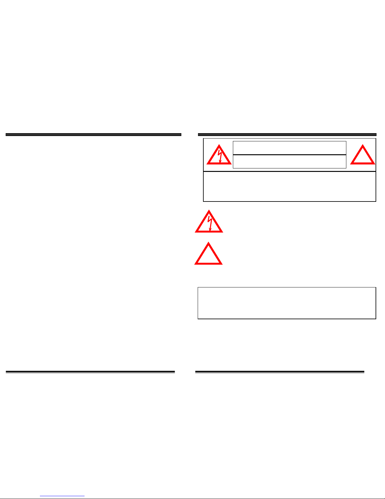
Explanation of two Symbols
The lightning flash with arrowhead symbol, within an equilateral
triangle, is intended to alert the user to the presence of uninsulated
"dangerous voltage" within the product's enclosure that may be of
sufficient magnitude to constitute a risk of electric shock to persons.
The exclamation point within an equilateral triangle is intended to
alert the user to the presence of important operating and maintenance(servicing) instructions in the literature accompanying the appliance.
THE GRAPHIC SYMBOLS WITH SUPPLEMENTAL MARKING ARE ON
THE BOTTOM OF THE SYSTEM.
!
CAUTION
RISK OF ELECTRIC SHOCK. DO NOT OPEN.
CAUTION:TO REDUCE THE RISK OF ELECTRIC SHOCK, DO NOT REMOVE
COVER (OR BACK). NO USER-SERVICEABLE PARTS INSIDE.
REFER SERVICING TO QUALIFIED SERVICE PERSONNEL.
!
1
Page 4

SAFETY INSTRUCTIONS
IMPORTANT SAFEGUARDS
All the safety and operating instructions should be read beforethe
appliance is operated and retained for future reference.
1. HEED WARNINGS - All warnings on the appliance and in the operating
instructions should be adhered to.
2. FOLLOW INSTRUCTIONS - All operating instructions should be
followed.
3. WATER AND MOISTURE - Do not use this video product near water -
for example, a bath tub, wash bowl, kitchen sink, laundry tub or swimming
pool, or in a wet basement.
4. POWER SOURCES - This product should be operated only from the type
of power source indicated on the marking label.
5. OVERLOADING - Do not overload outlets and extension cords, which
can result in a risk of fire or electric shock.
6. SERVICING - Do not attempt to service this product yourself. Opening or
removing covers may expose you to dangerous voltage or other hazards.
Refer all servicing or repairs to qualified service personnel.
215
TROUBLE SHOOTING
If the system does not function properly, check the following points.
Problems
Causes and remedies
Camera Monitor
- AC adapter not plugged in
- Power switch not turned on
- Monitor not turned on
No power
(no picture/sound)
- AC adapter not plugged
in
- Power switch not turned
on
- Adjust antenna direction
- Improper channel
- AC adapter not plugged
in
- Power switch not turned
on
Poor reception
Picture flickering
Picture too bright,
or too dark
-Strong spot light in the
field of view
-Lighting source in the
field of view
- Adjust antenna direction- Adjust antenna direction
Picture rolls and jumps
or scrambled picture
Because our products are subject to continuous improvement, SVC
reserves the right to modify product design and specifications
without notice and without incurring any obligation. E & OE.
- Adjust brightness control
on Monitor
Page 5

14
OPTIONAL ACCESSORIES
The following optional accessories are available to add to your existing system
Accessory Camera - Used to view other camera locations
(Available in B&W and Color).
For Information on accessories please contact
sales@kingavon.co.uk
7. DAMAGE REQUIRING SERVICE - Unplug this product from the wall outlet
and refer servicing or repairs to qualified service personnel under the following
conditions:
a. When the power supply cord or plug is damaged.
b. If liquid has been spilled or objects have fallen into the product.
c. If the product has been exposed to rain or water.
d. If the product does not operate normally by following the operating instructions.
Adjust only those controls that are covered by the operating instructions.
e. If the product has been dropped or the cabinet has been damaged.
f. When the product exhibits a distinct change in performance.
8. REPLACEMENT PARTS - When replacement parts are required, be sure the
service technician has used replacement parts that are specified by the manufacturer
or have the same characteristics as the original part. Unauthorized substitutions
may result in fire, electric shock, or other hazards.
9. SAFETY CHECK - Upon completion of any service or repairs to this video
product, ask the service technician to perform safety checks to determine if the
video product is in proper operating condition.
10. An appliance and cart combination should be moved with care.
Do not place this equipment on an unstable cart, stand, or table.
The equipment may fall, causing serious injury to a child or adult,
and serious damage to the equipment. Wall or shelf mounting
should follow the manufacturer's instructions and should be
done with a mounting kit approved by the manufacturer.
3
Page 6

13
OPERATION
USING SYSTEM WITH MORE THAN ONE CAMERA
Connections
Connect the supplied audio/video cable from the back of the monitor to
the Audio/Video In of the VCR.
RCA CABLES
Monitor
CHAPTER TABLE OF CONTENTS PAGE
1. CONTROLS AND FUNCTIONS
CAMERA……...........................................……………….................5
MONITOR.....………………..................................…………....……6, 7
2. INSTALLATION
CAMERA....................................................………………...........…8
MONITOR......................………………..........…………….........…9, 10
3. OPERATION
MULTIPLE CAMERAS…………………………………………………......11
AUTO/MANUAL MODE……………………………….….........……12, 13
OPTIONAL ACCESSORIES………………………………………………..14
4. SYSTEM OPERATION
OPERATION WITH MONITOR.....................................................11
OPERATION WITH MONITOR & VCR..........................................12
5. TROUBLE SHOOTING ...............................................................15
6. SYSTEM INCLUDES…...........…………...............................………16
7. SPECIFICATIONS....................................................................…17
4
AC Adapter
or plug from
Battery Case
Did you know?
You have the option of connectiing this system to a Time Lapse
VCR. A time lapse VCR provides you multiple recording options
allowing you to record up to 40 days using a standard T120 tape.
Refer to the optional accessories page for more details.
Page 7

CONTROLS AND FUNCTIONS
CAMERA
1. LENS
B&W CMOS Image sensor
2. MICROPHONE
Built-in condenser microphone provides
audio capability from camera to monitor/
television
3. 6 INFRA RED LED’s - Enhances
picture quality in low light conditions.
4. 2.4 GHz ANTENNA
High gain dipole antenna sends
Audio and Video signal to the
monitor.
5. BATTERY COMPARTMENT
Provides 4-5 hours of power
to camera. Requires 8 rechargeable
NiCd/NiMh batteries, or 8 1.5V
alkaline batteries
6. STAND MOUNTING SOCKET
Reinforcement lock for camera stand.
7. CHANNEL SELECTOR SWITCH
Slide switch for the channel 1-4 selection.
8. ON/OFF POWER SWITCH
Controls power to the camera. Note:
Please ensure you set the switch to the
OFF position before plugging the
AC adapter into the unit.
9. DC IN JACK
Plug the 12V DC (500mA) Adapter in here.
5
SIDE VIEWFRONT VIEW
1
2
3
5
7
4
6
8
9
BATTERY COMPARTMENT
12
MULTIPLE CHANNEL OPERATION
AUTO AND MANUAL VIEWING OPTIONS
This system is preset to Manual mode, with a dwell mode of 2 seconds.
In Auto mode, the LED light will be ON.
To manually view a specific camera location, press the Auto/Manual
button. Press the Ch. Select key to view the desired camera location.
Press the Auto/Manual button to return to the Auto Mode feature.
* NOTE: In the event of a power failure or a power breakdown, your
system will automatically switch back to Channel 1.
SELECTABLE DWELL SETTING
This system provides you the option of three selectable dwell options (2,
5 and 10 seconds) when set to Auto Mode. This system is preset to two
second selection.
Changing Dwell Mode
1. Press and hold the CH select button. The LED button will turn on
to indicate that it is set to 2 seconds.
2. Continue to press and hold the CH select button. The LED button
will flash at a one second interval to indicate that it is now set to
the 5 second interval
3. Continue to press and hold the CH select button. The LED button
will flash three times to indicate it is set to the 10 second interval.
Page 8

11
MULTIPLE CHANNEL OPERATION
USING SYSTEM WITH MORE THAN ONE CAMERA
This video security system allows you to view up to four different camera
locations. When connecting more than one camera to the monitor/camera
system, you will need to set each camera to a different channel (Channels
1-4).
AUTO SCANNING
This video security system provides you the option to automatically
switch between the four camera locations. If you have fewer than four
cameras, you can also set the system to scan between three or two
locations.
Setting Auto Scan to 2 or 3 camera locations
1. Press and hold the Auto/Manual button for more than 2 seconds.
All four LED lights on the front of the monitor will turn ON.
2. Continue to press and hold the Auto/Manual button. The Channel
4 LED button will turn off. The system is now set to scan
between three camera locations (Channel 1-3)
3. Continue to press and hold the Auto/Manual button. The Channel
3 LED button will now be turned off. The system is now set to
scan between two camera locations (Channel 1-2)
4. Continue to press and hold the Auto/Manual button to return to
the four camera viewing option (all four LED lights will be
illuminated)
CH2
CH3
CH4
CH1
CONTROLS AND FUNCTIONS
MONITOR
6
1
2
3
4
5
6
7
Video Output Jack
RCA jack for Video output connection.
Audio Output Jack
RCA jack for Audio output connection.
ON/OFF Switch
Speaker
Battery Compartment (not shown) –
Requires 10 C Batteries (not included).
Battery life Approximately 2-3 hours
Auto/Manual Slide Switch
Audio Mute Button
8
9
10
11
12
13
14
3
21
11
10
5
14
13
6
7
8
9
4
MONITOR BACK VIEWMONITOR FRONT VIEW
WIRELESS CAMERA – BATTERY OPTION
SLIDE IN
Location of Receiver Monitor controls
2.4GHz Antenna
High gain dipole patch antenna receives
audio and video signal from the camera.
CRT - 5.5” Diagonal
Brightness Control
Contrast Control
Volume Control
Channel Selector
Switch for channel 1-4-AUTO selection.
DC Input Jack
Connect the supplied 13.5V DC 1.0A
AC adapter.
Page 9

7
CONTROLS AND FUNCTIONS
10
INSTALLATION
Ensure the power switch on the monitor and camera are set to
the OFF position before proceed following steps.
Try to position both the Camera and Monitor as high off the ground as possible for
better picture reception.
NOTE
Camera
(1) Connect the power adapter to the camera power input and ensure the camera is turned
‘ON’ Ensure the camera is set to channel 1
Monitor
(1) Connect the supplied power adapter to the power input of the monitor OR connect the
DC plug from the battery box to the DC input jack at the back of the monitor
(2) Use the channel selection switch button and ensure the monitor is set to the same channel
as the camera to view the picture. Note: If you experience transmission reception
problems (eg. poor picture), you may need to select another channel on the camera and
monitor and/or adjust the antennas on the monitor and camera to ensure they are pointing
at each other.
(3) Adjust the volume to the desired level. You may also mute the audio option by pressing
the mute button which is located at the front of the monitor.
(4) Adjust the brightness and contrast levels as required
NOTE
MONITOR
CAMERA
WIRELESS CAMERA – INSTALLATION
1. Attach the stand base to the wall or ceiling where you want to
install the camera. Locate a wall stud or ceiling joist and secure bracket using the
three supplied screws.
2. Attach the camera to the stand and firmly tighten the swivel.
3. Attach the camera with the stand to the stand base and firmly tighten the joint knob
on the stand base.
4. Connect the supplied 12V 500mA AC adapter to the DC IN jack at the rear of the
camera and plug it into the electrical outlet.
Your wireless camera has both AC or battery option. When using the AC option with
rechargeable batteries, your camera will automatically switch to back up battery feature
during a power outage providing you with uninterrupted power to the camera. The
battery option also provides you the flexibility to move the camera from room to room.
WIRELESS CAMERA - AC OPTION ONLY
1. Ensure the power switch on the camera is turned OFF.
2. Connect one end of the power supply to the DC IN jack locatedat the back of the
camera. Plug the other end into an electrical outlet
WIRELESS CAMERA - USING RECHARGEABLE BATTERIES
1. Insert 8 rechargeable ‘AA’ batteries (not included) into the camera battery
compartment. WARNING: TO PREVENT INJURY AND/OR DAMAGE TO THE
UNIT, ENSURE THE BATTERIES ARE ALIGNED PROPERLY AND BATTERY
TYPES ARE NOT MIXED.
2. Ensure the slide switch labeled Recharge/Alkaline is set to the ‘Rechargeable’
setting.
3. Carefully slide the battery compartment into the camera
4. Ensure the power switch on the camera is turned OFF.
5. Connect one end of the power supply to the DC IN Jack located at the back of the
camera. Plug the other end into an electrical outlet.
WIRELESS CAMERA - USING ALKALINE BATTERIES
1. Insert 8 alkaline ‘AA’ batteries (not included) into the camera battery compartment.
WARNING: TO PREVENT INJURY AND /OR DAMAGE TO THE UNIT, ENSURE
THE BATTERIES ARE ALIGNED PROPERLY AND BATTERY TYPES ARE NOT
MIXED
2. Ensure the slide switch labeled Rechargeable/Alkaline is set to the ‘Alkaline’
setting.
3. Carefully slide the battery compartment into the camera
4. Ensure the power switch on the camera is turned OFF.
5. Connect one end of the power supply to the DC IN Jack located at the back of the
camera. Plug the other end into an electrical outlet
Page 10

9
MONITOR
1.Connect the supplied AC adapter to the DC INPUT JACK at the rear
of the receiver monitor and plug it into the 120V electrical outlet.
Or
1a. Connect the DC Plug from Battery Case to the DC INPUT JACK at
the rear of the Receiver Monitor.
DC INPUT Jack
2. INSTALLATION
BATTERY CASE & COMPARTMENT
Remove the battery case by unscrewing the bolt at the bottomof the monitor and
sliding the battery case out. This system requires 10 ‘C’ sized batteries (not
included)
Warning : To prevent injury and/or damage to the unit, ensure that the batteries
Are aligned properly and battery types are not mixed.
13.5V 1.0 A
AC Adapter
8
2. INSTALLATION
CAMERA INSTALLATION
1. Attach the stand base to the wall or ceiling where you want to
install the camera. Locate a wall stud or ceiling joist and secure bracket using the
three supplied screws.
2. Attach the camera to the stand and firmly tighten the swivel.
3. Attach the camera with the stand to the stand base and firmly tighten the joint
knob on the stand base.
4. Connect the supplied 12V 500mA DC adapter to the DC IN jack at the rear of the
camera and plug it into the electrical outlet.
Plug
 Loading...