

Page 1
OPERATING INSTRUCTIONS
●
Before operating the unit, please read this manual thoroughly
2507W41AV001A Rev.1A
DATE10-MAR-2000
2.4 GHz WIRELESS
VIDEO SECURITY SYSTEM
Model SG 6040
Page 2

7.SPECIFICATIONS
WIRELESS CAMERA
Image sensor
Lens
Total Pixels
Scanning system
Scanning frequency
Sync. system
Resolution
Min. illuminations
Video Output
Gamma characteristics
Auto Iris
Microphone
Transmitting frequency
Modulation
RF out level
Video Output level
Antenna
Oper. temperature
Power source
Dimensions
Weight
1/3" B/W CCD imager
F2.0/f 3.7mm, 92°wide-angle lens
537(H)
x 505
(V), 270,000 pixels
2:1 interlace
15.734 KHz(H) 59.94Hz(V)
Internal Synchronization
420 TV lines horizontal
0.5 Lux at F2.0
1.0Vp-p/75 Ohm
r=0.45
Electrical Auto Iris
Shutter sensitivity :1/60-1/100,000
Electret Condenser
2.4 GHz-2.4835 GHz(2Ch)
FM
90dBu/V, 3m
1.0Vp-p/75 Ohm
Directional high gain antenna
-14°to + 122°F
DC12V 500mA AC Adapter
2.72”(W) x1.89”(H) x5.75”(D)
Appro 9 OZ
WIRELESS RECEIVER MONITOR
Receiving frequency
2.4GHz - 2.4835GHz (2CH & AUTO)
Output level
1.0Vp-p/75ohm (Video),
1.35Vp-p (Audio)
Sensitivity
-25dB to -80dBm
Antenna
Directional high gain antenna
Resolution
More than 280 lines
Sound output
0.5 Watt.
Power Source
DC12-14V 1.2A AC Adapter
Dimension
7.09”(W)8.2”(H)8.07”(D)mm
(W/O Battery
Case)
7.09”(W)9.45”(H)8.07”(D)mm
Oper. Temperature
-14to + 122F
Weight
Appro 45 OZ
(W/O Battery Case)
Appro 50 OZ
17
FCC CLASS B NOTICE
Note:
This equipment has been tested and found to comply with the limits For a Class B
digital device, pursuant to Part 15 of the FCC Rules. These limits are designed to
provide reasonable protection against harmful interference in a residential
installation. This equipment generates, Uses and can radiate radio frequency energy
and, if not installed and used in accordance with the instruction, may cause harmful
interference to radio communications. However, there is no guarantee that
interference will not occur in a particular installatio n. If this equipment does cause
harmful interference to radio or television reception, (whic h can be d etermined by
turning the equipment off and on), the user is encouraged to try to correct the
interference by one or more of the following measures:
• Reorient or relocate the receiving antenna.
• Increase the separation between the equipment and receiver.
• Connect the equipment into an outlet on a circuit different from that to which the
receiver is connected.
• Consult the dealer or an experienced radio or television technician for help.
Page 3
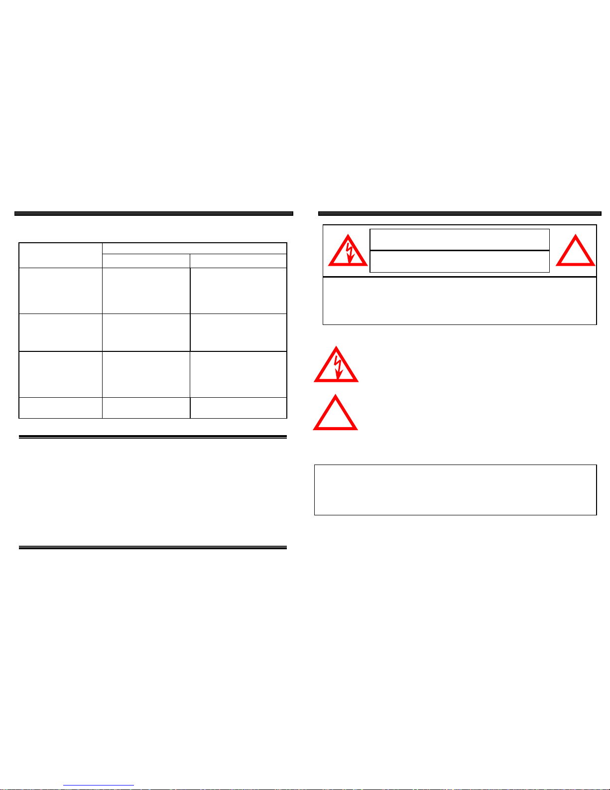
Explanation of two Symbols
The lightning flash with arrowhead symbol, within an equilateral
triangle, is intended to ale r t th e use r to th e pres enc e of unin sulated
"dangerous voltage" within the product's enclosure that may be of
sufficient magnitude to constitute a risk of electric shock to persons.
The exclamation point with in an equ ila t e r altriangle is intended to
alert the user to the presence of important operating and maintenance(servicing) instructions in the literature accompanying the appliance.
THE GRAPHIC SYMBOLS WITH SUPPLEMENTAL MARKING ARE ON
THE BOTTOM OF THE SYSTEM.
WARNING:To prevent fire or shock hazard, do not expose this
appliance to rain, water, or wet locations. Do not insert
any metallic object through the ventilation grills.
IMPORTANT SAFETY INSTRUCTIONS
This wireless A/V equipment is provided with a polarized alternating-current line
plug (a plug having one blade wider than the other). This plug will fit into the
power outlet only one way. This is a safety feature. If you are unable to insert
the plug fully into the outlet, try reversing the plug. If the plug still fail to fit,
contact your electrician to replace your obsolete outlet. Do not defeat the safety
purpose of the polarized plug.
!
CAUTION
RISK OF ELECTRIC SHOCK. DO NOT OPEN.
CAUTION
TO REDUCE THE RISK OF ELECTRIC SHOCK, DO NOT REMOVE
COVER (OR BACK). NO USER-SERVICEABLE PARTS INSIDE.
REFER SERVICING TO QUALIFIED SERVICE PERSONNEL.
!
1
5. TROUBLE SHOOTING
If the system does not function properly, check the following points before contact the
service center.
Basic system includes
1- Wireless Camera
1- Wireless A/V Receiver Monitor
2- AC Ad a p t er s
--12V/0.5A Adapter (Camera)
--12-14V/1.2A Adapter (Monitor)
1- RCA A/V Cables or Scart A/V Cables (Option)
1- Owner's Manual/Warranty Card
1- Camera Mount
1- Warni ng Decal
Problems
Causes and remedies
Camera Monitor
- AC adapte r not plugged in
- Power switch not turned on
- Monitor not turned on
No power
(no picture/sound)
- AC adapte r not plugged
in
- Power switch not turned
on
- Adjust antenna direction
- Improper channel 1-2
selection
- AC adapter not plug ged
in
- Power switch not turned
on
Poor reception
Picture flickering
Picture too bright,
or too dark
-Strong spot light in the
field of view
-Lighting source in the
field of view
- Adjust brightness control
on Monitor
- Adjust antenna direction- Adjust antenna direction
Picture rolls and jumps
or scrambled picture
16
Page 4

SAFETY INSTRUCT IONS
I MPORTANT SAFEGUARDS
All the safety a nd op erating inst ruc ti ons should be read befo re the
app l iance is operated and reta ined for fu ture refere nc e.
1. HEED WARNINGS
- All warnings on the appliance and in the operating
instructions should be adhered to.
2. FOLLOW INSTRUCTIONS
- All operating instructions should be
followed.
3. WATER AND MOISTURE
- Do not use this vide o pr o duct ne ar wat e r for example, a bath tub, wash bowl, kitchen sink, laundry tub or swimming
pool, or in a wet basement.
4. POWER SOURCES
- This product should be operated only from the type
of power source indicated on the marking label.
5. POLARIZATION
- This video monitor equipment is provided with a
polarized alternating current line plug (a plug having one blade wider than
the other ). This plug will fit into the power outlet only one way. This is a
safety feature. If you are unable to insert the plug fully into the outlet, try
reversing the plug. If the plug should still fail to fit, contact your electrician
to replace your obsolete outlet. Do not defeat the safety purpose of the
polarized plug.
6. OVERLOADING
- Do not overload outlets and extension cords, whic h
can result in a risk of fire or electric shock.
7. SERVICING
- Do not attempt to service this product yourse lf. Opening or
removing covers may expose you to dangerous voltage or other hazards.
Refer all servicing or repairs to qualified service personnel.
2.Turn on the Camera and all Receiver Monitors. Search the chan nel 1-2 by
using channel Selector Switch on the Camera and Receivers Monitor and
select best one for optimum reception in your area.
3.Adjust the antenna direction as necessary.
All Receiver Monitor and Camera units must be set to same channel.
NOTE
152
4.MULTIPLE CHANNEL OPERATION
ONE CAMERA BY MULTIPLE RECEIVER OPERATION
You can receive A/V signal from the Wireless Camera on several Receiver monitors
in remote location at the same time using one Wireless C amera with multiple
Wireless Receiver as many as you want.
Channel Selector
Switch
Transmitter
1.Connect all Receiver Monitors with or without VCR using RCA cables.
(see instructions on page 12)
Be sure to set the Power Switches on the Camera and the Receiver to the OFF
position before proceeding with the follo wing steps.
System includes only one Receiving Monitor and one Sending unit Additio nal
units are optional.
NOTE
NOTE
Receiver Monitor-1
Channel Selector
Switch
Page 5

8. DAMAGE REQUIRING SERVICE
- Unplug this product from the wall outlet
and refer servicing or repairs to qualified service personnel under the following
conditions
a. When the power supply cord or plug is damaged.
b. If liquid has been spilled or objects have fallen into the p r oduct.
c. If the product has been exposed to rain or water.
d. If the product does not operate normally by following the operating instructions.
Adjust only those controls that are covered by the operating instructions.
e. If the product has been dropped or the cabinet has been damaged.
f. When the product exhibits a distinct change in performance.
9. REPLACEMENT PARTS
- When replacement parts are required, be sure the
service technician has used replacement parts that are specified by the manufacturer
or have the same characteristics as t he or iginal part. Unauthorized substitutions
may result in fire, electric shock, or other hazards.
10. SAFETY CHECK
- Upon completion of any service or repairs to this video
product, ask the service technician to perform safety checks to determine if the
video product is in proper operating condition.
11. An appliance and cart combination should be moved with care.
Do not place this equipment on an unstable cart, stand, or table.
The equipment may fall, causing serious injury to a child or adult,
and serious damage to the equipment. Wall or shelf mou nting
should follow the manufacturer's instructions and should be
done with a mounting kit a pp r o ved by the ma nu f ac t urer.
314
4.MULTIPLE CHANNEL OPERATION
ONE RECEIVER MONITOR BY TWO CAMERAS OPERATION
(Cont'd)
4.Turn on the Receiver Monitor and select the channel 1-2 one by one manually Channel
Selector switch on the Receiver Monitor.
5.Adjust the antenna direction as necessary.
Page 6

CHAPTER TABLE OF CONTENTS PAGE
1. CONTROLS AND FUNCTIONS
WIRELESS CCD CAMERA...........................................................5
WIRELESS MONITOR.....………………...........................................6
2. INSTALLATION
WIRELESS CAMERA.................................................................…8
WIRELESS MONITOR......................……………….......................…9
ADJUSTING THE A/V ANTENNA..........................................….. 10
3. SYSTEM OPERATION
OPERATION WITH MONITOR.....................................................11
OPERATION WITH MONITOR & VCR..........................................12
4. MULTIPLE CHANNEL OPERATION
ONE RECEIVER MONITOR BY TWO CAMERAS OPERATION......13
ONE CAMERA BY TWO RECEIVERS OPERATION.............…......15
5. TROUBLE SHOOTING ...............................................................16
6. BASIC SYSTEM INCLUDES.....................................................…16
7.SPECIFICATIONS.....................................................................…17
134
4.MULTIPLE CHANNEL OPERATION
ONE RECEIVER MONITOR BY TWO CAMERAS OPERATION
1.Place all cameras at your desired location.
2.Connect the Receiver Monitor with or without VCR using RCA cables.
(see instructions on page 12)
3.Turn on all Cameras. The Cameras must use different channel. Select the channel
1-2 by using Channel Selector Switch on each Camera unit.
Second Camera is not included.
NOTE
Be sure to set the Power Switches on the Camera and the Receiver
Monitor to the OFF position before proceed following steps.
NOTE
Cameras
Ch1
Ch2
Channe l Selector
Switch
Receiver Monitor
This wireless Camera & Monitor System consists of a Wireless Camera
and a 5" B/W Monitor. You can connect up to two Cameras to the
monitor.
For proper usage and application, please read the instruction manual.
Channel Selector
Switch
Page 7

1.CONTROLS AND FUNCTIONS
WIRELESS CCD CAMERA
1. LENS
1/3" B/W CCD Image sensor with
built-in 92°fixed wide-angle lens.
2. MICROPHONE
Built-in condenser microphone.
(one-way audio)
3. LED-POWER INDICATOR
Indicates that the camera is turned on.
4. 2.4 GHz A/V ANTENNA
High gain directional patch antenna
sends A/V signal to the receiver.
5. STAND MOUNTING SOCKET
Reinforcement lock for camera stand.
6. CHANNEL SELECTOR SWITCH
Switch for the channel 1-2 selection.
7. POWER SWITCH ON/OFF
Controls power. Be sure to set the
switch to off position before plugging the
AC adapter into the unit and AC outlet.
8. AUDIO/VIDEO OUT JACKS
EAR Audio/Video-Out jacks for wire
mode operation.
9. DC IN JACK
Plug the 12V(500mA) AC Adapter in here.
REAR VIEW
FRONT VIEW
4
2
3
1
5
7
6
8 9
512
VCR Rear
3.SYSTEM OPERATIO N
OPERATION WITH MONITOR & VCR
Both Camera and Receiver Monitor units must be set to s ame channel.
NOTE
NOTE
Be sure to set the Power Switch on both the Receiver Monitor and Camera
to the OFF position before proceeding with the following steps.
NOTE
RCA Cable (1)
Camera
(1) Connect supplied power adapter to Camera power input.
(2) Slide the channel selector switch to CH 1~2 of your choice.
Receiver Monitor
(1) Connect supplied power adapter or plug from Battery Case t o Receiver Monitor
power input.
(2) Search the channel 1-2 by using Channel Selector Switch on the Receiver Monitor and
Camera and select best one for optimum reception in your area.
(3) The fine tuning knob should be kep t in the center position for best reception.
(4) Try to position both the Camera and Monitor as high off the ground as possible for
better reception.
(5) Connect A/V output signal to your VCR recorder. If you want to record the camera signal.
(6) Volume Control--Adjust the knob for desired volume level.
(7) Bright and Contrast Control--If the picture is too bright or too dark, adjust the bright
and contrast controls to suit.
(8) Vertical Hold Control--If picture rolls up and down
(as illustrated) adjust the vertical hold control.
(9) Adjust the antenna direction as necessary.
Receiver Monitor
12-14V 1.2A
AC Adapter
or plug from
Battery Case
Video Output Jack
Audio Output Jack
DC Input
Jack
Channel Selector
Switch
Contrast Control
V-Hold Control
Bright Control
Page 8

REAR VIEW
1.CONTROLS AND FUNCTIONS
WIRELESS MONITOR
FRONT VIEW
Location of Receiver Monitor controls
2.4GHz Antenna
High gain directional patch antenna
receives A/V signal from the camera.
CRT
5” Diagonal
Brightness C o ntrol
Contrast Control
OFF/Volume Control
Channel Selector Switch
Switch for channel 1-2-AUTO selection.
DC Input Jack
Connect the supplied 12-14V 1.2A
AC adapter.
1
2
3
4
5
6
7
8
9
10
Video Output Jack
EAR jack for Video output connection.
Audio Output Jack
EAR jack for Audio output connection.
V-Hold Control
Speaker
Battery Case
DC plug
Bolt.
116
11
1
2
3
5
4
7
9 8 10
11
6
3.SYSTEM OPERATIO N
OPERATION WITH MONITOR
Be sure to set the Power Switch on the Receiver Monitor and Camera to
the OFF position before proceed following steps.
Both Camera and Receiver Monitor units must be set to same channel.
NOTE
12V 500mA
AC Adapter
Camera
Power Switch Channel Selector
Switch
Camera
(1) Connect power adapter(12V/500mA) to Camera power in put.
(2) Slide the channel selector switch to CH 1~2 of your choice.
Receiver Monitor
(1) Connect supplied power adapter or plug from Battery Caseto Receiver Monitor
power input.
(2) Search the channel 1-2 by using Channel Selector Switch on the Receiver Monitor and
Camera and select best one for optimum reception in your area.
(3) The fine tuning knob should be kept in the center position for best reception.
(4) Try to position both the Camera and Monitor as high off the ground as possible for
better reception.
(5) Volume Control--Adjust the knob for desired volume level.
(6) Bright and Contrast Control--If the picture is too bright or too dark, adjust the bright
and contrast controls to suit.
(7) Vertical Hold Control--If picture rolls up and down
(as illustrated) adjust the vertical hold control.
(8) Adjust the antenna direction as necessary.
NOTE
Receiver Monitor
12-14V 1.2A
AC Adapter
or plug from
Battery Case
Video Output Jack
Audio Output Jack
DC Input
Jack
Channel Selector
Switch
Contrast Control
V-Hold Control
12
13
14
12
13
14
Bright Control
Page 9

710
A/V Antenna
Front
(Patterned side)
2.INSTALLATION
ADJUSTING THE A/V ANTENNA
NOTE :
The front (patterned side) of the A/V antennas on both camera and receiver
monitor must face each other for optimum performance as both are
directional high gain antennas.
IMPORTANT NOTE FOR CHANNEL SELECTION
Search the channel 1-2 and select best one for optimum reception in your area.
Both Camera and Receiver Monitor must be set to same channel.
Maximum antenna rotation 270°in
both clockwise and anti clockwise
Caution : Do not rotate the
antenna 360°or it will cause
antenna mechanis m damaged
Receiver Monitor
Wireless Camera
REAR VIEW
1.CONTROLS AND FUNCTIONS
WIRELESS RECEIVER MONITOR (without Battery Case) (Optional)
FRONT VIEW
Location of Receiver Monitor controls
2.4GHz Antenna
High gain directional patch antenna
receives A/V signal from the camera.
CRT
5” Diagonal
Brightness C o ntrol
Contrast Control
OFF/Volume Control
Channel Selector Switch
Switch for channel 1-2-AUTO selection.
1
2
3
4
5
6
7
8
9
10
DC Input Jack
Connect the supplied 12-14V 1.2A
AC adapter.
Video Output Jack
EAR jack for Video output connection.
Audio Output Jack
EAR jack for Audio output connection.
V-Hold Control
Speaker
11
1
2
3
5
47
9 8
10
11
6
Page 10

8 9
WIRELESS MONITOR
1.Connect the supplied 1.2A AC adapter to the DC INPUT JACK at the rear
of the receiver monitor and plug it into the 230V(or 120V) AC outlet.
Or 1a. Connect the DC Plug from Battery Case to the DC INPUT JACK at
the rear of the Receiver Monitor.
DC INPUT Jack
12-14V 1.2A
AC Adapte r
2.INSTALLATION2.INSTALLATION
WIRELESS CAMERA
1.Attach the stand base to the wall or ceiling where you wa nt to
install the camera. Locate a wall stud or ceiling joist and secure bracket using the
three supplied screws.
2.Attach the camera to the stand and firmly tighten the swivel.
3.Attach the camera with the stand to the stand base and firmly tighten the joint knob
on the stand base.
4.Connect the supplied 12V 500mA AC adapter to the DC IN jack at the rear of the
camera and plug it into 230V (or 120V) AC outlet.
DC 12V 500 mA
AC Adapte r
Battery Case & Compartment
Remove the battery case by screwing down bolt at the rear side and sliding out
case. The battery feature requires 10 Pcs ‘C’ sized batteries.
Warning : To prevent injury. Do not reverse any Battery & Do not mix
Battery type.
Plug
Plug
 Loading...