

Page 1
2.4 GHz 1.8” COLOR TFT LCD
MONITOR WITH WIRELESS
CAMERA
Instruction Manual
English Version1.0
MODEL:
SG5550CL
Copyright © 2005 Strategic Vista International Inc
www.lorexcctv.com
Page 2
CAUTION
RISK OF ELECTRIC SHOCK. DO NOT OPEN.
CAUTION: TO REDUCE THE RISK OF ELECTRIC SHOCK, DO NOT REMOVE
COVER (OR BACK). NO USER-SERVICEABLE PARTS INSIDE. REFER
SERVICING TO QUALIFIED SERVICE PERS ON NEL.
Explanation of two Symbols
The lightning flash with arrowhead symbol, within an
equilateral triangle, is intended to alert the user to the
presence of uninsulated "dangerous voltage“ within the
product's enclosure that may be of sufficient magnitude to
constitute a risk of electric shock to persons.
The exclamation point within an equilateral triangle is
intended to alert the user to the presence of important
!
THE GRAPHIC SYMBOLS WITH SUPPLEMENTAL MARKING ARE ON
THE BOTTOM OF THE SYSTEM.
operating and maintenance(serv icing) instructions in
the literature accompanying the appliance.
!
WARNING: To prevent fire or shock hazard, do not expose this unit to
rain, water, or wet locations. Do not insert any metallic object
through the ventilation grills
FCC CLASS B NOTICE
Note:
This equipment has been tested and found to comply with the limits For a Class
B digital device, pursuant to Part 15 of the FCC Rules. These limits are
designed to provide reasonable protection against harmful interference in a
residential installation. This equipment generates, uses and can radiate radio
frequency energy and, if not installed and used in accordance with the
instruction, may cause harmful interference to radio communications.
However, there is no guarantee that interference will not occur in a particular
installation. If this equipment does cause harmful interference to radio or
television reception, (which can be determined by turning the equipment off
and on), the user is encouraged to try to correct the interference by one or more
of the following measures:
.
• Reorient or relocate the receiving antenna
• Increase the separation between the monitor and the camera.
• Connect the equipment into an outlet on a circuit different from that to which
other devices may be connected.
• Consult the dealer or an experienced radio or television technician for help.
• Please review the troubleshoo ting section of this manual
i
Page 3

SAFETY INSTRUCTIONS
IMPORTANT SAFEGUARDS
All the safety and operating instructions should be read before the
appliance is operated and retained for future reference.
1. HEED WARNINGS - All warnings on the appliance and in the operating
instructions should be adhered to.
2. FOLLOW INSTRUCTIONS - All operating instructions should be
followed.
3. WATER AND MOISTURE - Do not use this video product near water –
for example, a bath tub, wash bowl, kitchen sink, laundry tub or
swimming pool, or in a wet basement.
4. POWER SOURCES - This product should be operated only from the type
of power source indicated on the marking label.
5. OVERLOADING - Do not overload outlets and extension cords, which
can result in a risk of fire or electric shock.
6. SERVICING - Do not attempt to service this product yourself. Opening or
removing covers may expose you to dangerous voltage or other hazards.
Refer all servicing or repairs to qualified service personnel.
7. DAMAGE REQUIRING SERVICE - Unplug this product from the wall
outlet and refer servicing or repairs to qualified service personnel under
the following conditions:
a. When the power supply cord or plug is damaged.
b. If liquid has been spilled or objects have fallen into the product.
c. If the product has been exposed to rain or water.
d. If the product does not operate normally by following the operating
instructions. Adjust only those controls that are covered by the
operating instructions.
e. If the product has been dropped or the cabinet has been damaged.
f. When the product exhibits a distinct change in performance.
8. REPLACEMENT PARTS - When replacement parts are required, be
sure the service technician has used replacement parts that are
specified by the manufacturer or have the same characteristics as the
original part. Unauthorized substitutions may result in fire, electric
shock, or other hazards.
9. SAFETY CHECK - Upon completion of any service or repairs to this
video product, ask the service technician to perform safety checks to
determine if the video product is in proper operating condition.
10. An appliance and cart combin ation should be mov ed with care.
Do not place this equipment on an unstable cart, stand, or table.The
equipment may fall, causing serious injury to a child or adult, and
serious damage to the equipment. Wall or shelf mounting should
follow the manufacturer's instructions and should be done with
a mounting kit approved by the manufacturer.
ii
Page 4

TABLE OF CONTENTS
PAGE
INTRODUCTION & FEATURES………………………………………
SYSTEM INCLUDES……………………………………………… …..
CONTROLS AND FUNCTIONS
Monitor Controls – Front Panel ...….……………………..……...
Monitor Controls – Side Panels .....................……….….....……
Camera Controls ……………………………………………… …..
Docking Station Co ntrols ………………………………………….
INSTALLATION
Camera ............................................. ......... ……………….…....
Monitor .................................. ...................................………......
SYSTEM OPERATION
Additional camera connection…………………………………….
Alarm Alert …………………………………………………………
Auto & Manual Viewing Options………………………………….
Auto Scanning………………………………………………………
Selectable Dwell Setting s………… …………… …… ……………
Connecting The Monitor To A VCR ……...………………..…….
1
2
3
4
5
6
7
8
9
10
10
11
11
12
OPTIONAL ACCESSORIES ..........................................................
TROUBLE SHOOTING .......................... ....................………..…...
TECHNICAL SPECIFICATIONS ................................. .......... ...... ...
CARE & MAINTENANCE……………………………..……………….
13
14
15
16
iii
Page 5

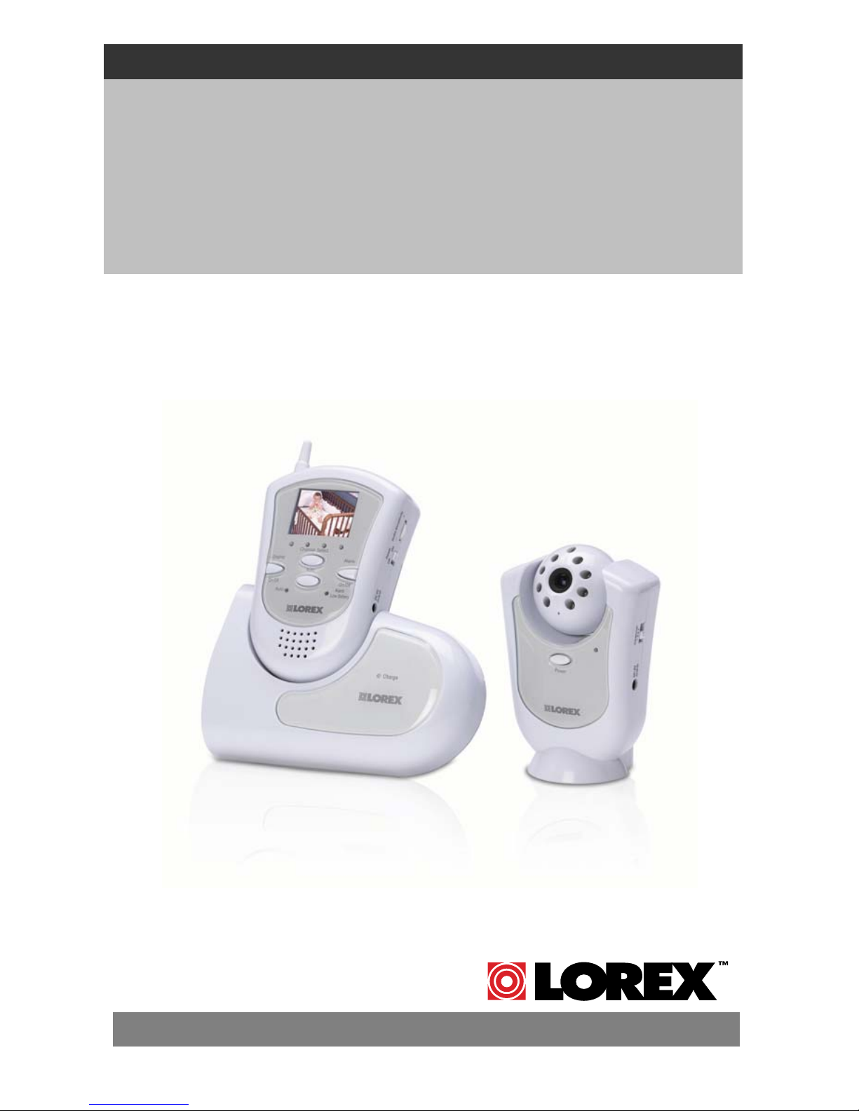
INTRODUCTION:
Thank you for purchasing the 2.4GHz Wireless 1.8” LCD Color Video
System. This is an ideal solution for monitoring your child, business or
home. The package contains a portable LCD monitor, a 2.4 GHz
wireless color camera with Night Vision capability, and a power
charging docking station for the monitor.
The system is expandable up to 4 cameras (additional cameras sold
separately) with the convenience of auto-sequencing between camera
locations. Use the Listen-in Audio feature to pick up sound within a
specific location. Avoiding the hassle of running wires, this system is
easy to install and operate for your immediate security applications.
The RCA audio/video outputs on the Docking Station allow you to view
video on a larger screen, or connect to a VCR for recording purposes.
To learn more about this 2.4GHz Wireless 1.8” LCD Color Video
System and our complete range of accessory products, please visit our
website at:
www.lorexcctv.com
FEATURES:
• Portable 2.4 GHz Color wireless camera
• Portable 2.4 GHz receiver handset with a built in 1.8” TFT full color display
• Includes Charging Docking Station with A/V Out
• 4 channel selection
• Built in CDS sensor to turn on IR LED at night time
• Up to 300 feet wireless transmission
• Flexible – move camera & monitor from room to room
• Listen-in audio
• Auto scanning – up to four cameras
• Camera and monitor with AC or battery option
• Compatible with all Lorex 2.4 GHz wireless devices
• Connect up to four cameras (additional cameras sold separately)
1
Page 6

SYSTEM INCLUDES:
1.8” LCD screen –
2.4 GHz Color Monitor
Docking Station / Charger
for Monitor
2.4 GHz Color Wireless Camera
with 8 Infra-red emitters
Owner’s Manual
Also includes:
1 – 6V DC 300mA Adapter (Camera)
with battery option (4 “AA”, not included)
1 – 6V DC 800mA Adapter (Monitor)
with battery option (4 “AA”, not included)
1 – RCA Audio/Video Cables
Mounting hardware for Camera
Window decals
2
Page 7
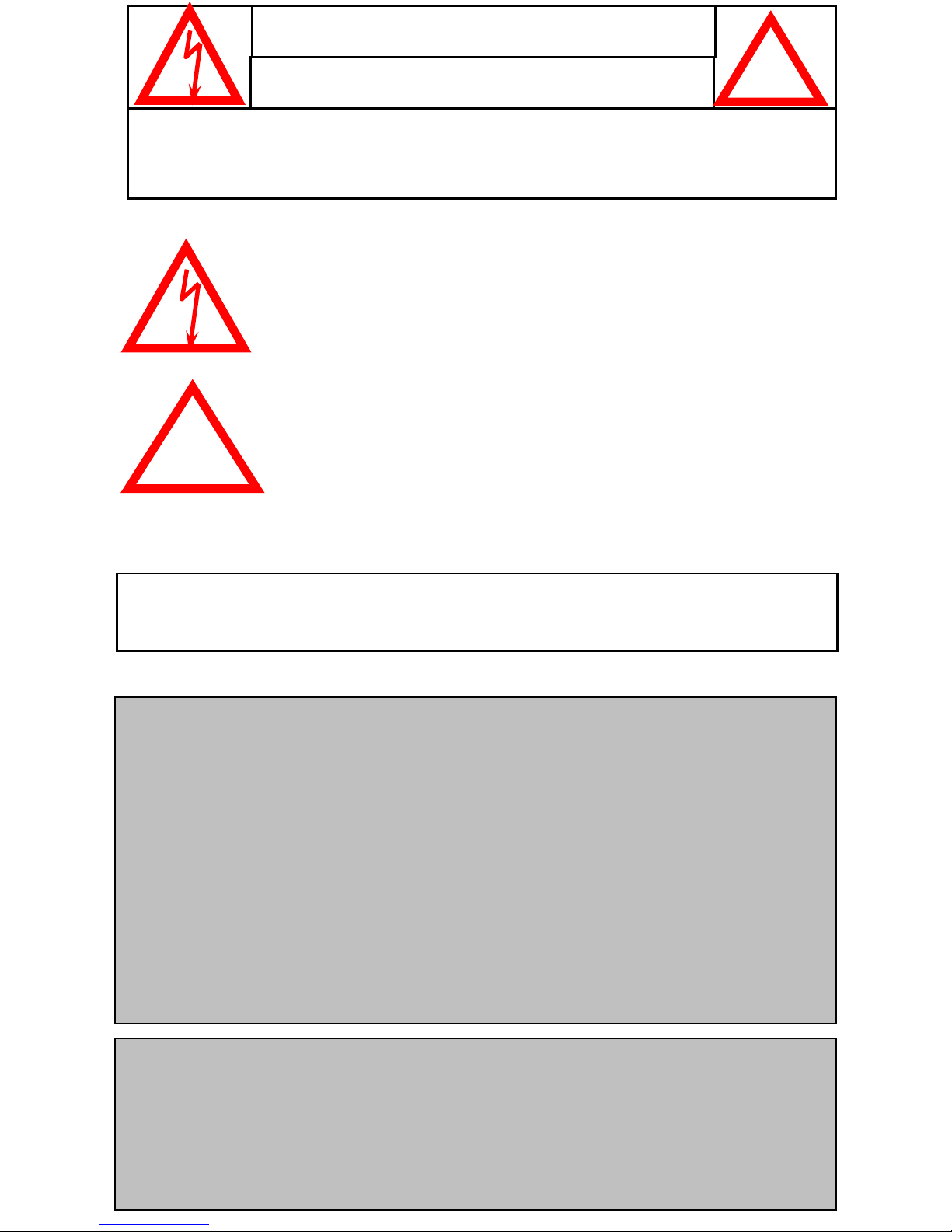
MONITOR CONTROLS – FRONT PANEL
1
2
3
4
5
6
7
8
9
10
1. 2.4GHz Antenna - High gain dipole antenna receives audio and video
signal from the camera.
2. LCD - 1.8” Color Screen.
3. Channel Indicator - Shows which Channel the monitor is set to (1-4).
Channel 1 is represented on the left side - Channel 4 on the right side.
4. Channel Selector - Manually switches between channels 1-4.
5. Display On/Off - Turns the LCD Screen Display On/Off on the monitor.
Note: pressing this button turns the monitor to Standby mode. Video will
automatically reappear in the event of an Alarm, and Audio remains ON.
6. Auto Button - Initiates automatic rotation between channels 1-4.
Press this button again to terminate Auto mode.
7. Auto Indicator - Illuminates when the system is in Auto mode.
8. Alarm On/Off - Press for 2 sec to set the Alarm mode On/Off. For more
information on the Alarm feature, please refer to page 10.
9. Alarm / Low Battery Indicator - Illuminates when Alarm mode is set, and
blinks slowly when the Battery power is low.
10. Speaker - Emits sound from the camera location.
.
.
3
Page 8

MONITOR CONTROLS – SIDE PANELS
4
6
1
7
2
5
3
1. Audio Sensitivity - Sets the sensitivity level for the alarm Audio
triggering (refer to page 10 for more information).
2. ON/OFF Switch - Switches the power on the monitor ON or OFF.
3. DC Input Jack - Connect to the supplied 6V DC 800 mA AC adapter.
Note: If Power is connected via the Docking Station, this input is not
required as the monitor will draw P ower from the Docking Station.
4. Belt Clip / Stand - in the upright position, this clip serves as a belt clip
for convenient portability. You can also lower this piece to serve as a
Stand for the monitor (without the Docking Station).
5. Battery Compartment – Requires 4 “AA” Batteries (not included).
6. Brightness Control - Allows you to adjust t he brightness of the picture.
7. Volume Control – Turn this dial to adjust the volume on the monitor.
4
Page 9

CAMERA CONTROLS
1
2
3
4
5
6
7
8
1. CDS Sensor - Turns on the IR emitters in low light conditions.
2. Infrared LED’s - Enhance the picture quality in low light conditions.
3. Lens - Color CMOS Image Sensor.
4. Microphone - Built-in condenser microphone provides listen-in audio
capability from camera to monitor.
5. ON/OFF Po wer Button - Controls power to the camera.
6. Channel Selector Switch - Slide switch set the camera’s channel (1-4)
7. DC IN Jack - Connects to the 6V DC (300mA) adapter.
8. Battery Compartment (not shown) - Requires 4 “AA” Batteries
(not included).
5
Page 10

DOCKING STATION CONTROLS
2
1
3
4
1. Cradle - Carefully slide the monitor downward into the docking cradle.
The monitor now has the added feature of Audio / Video Out for
connection to a larger monitor (such as a TV) or a VCR.
2. Charge Indicator - Illuminates when both Power and the Monitor are
connected. The Docking Station will recharge the batt eries in the
monitor provided that you have inserted Rechargeable batteries.
(Please refer to Page 8 for recharging time.)
3. Video and Audio Output Jacks - RCA jacks for A/V Output
connection to another video source (using the supplied A/V cable).
4. DC IN Jack - Connects to the 6V DC 800mA adapter, the same one
used for the monitor.
6
Page 11

CAMERA INSTALLATION
NOTE
Ensure the power switch on the monitor and camera are set to
the OFF position before proceeding with the following steps.
OPTION #1 OPTION #2
DESK
WALL
Option 1: You can place the camera on a desk or any leveled surface.
Select a location that is near an AC outlet and within reach of the AC
adapter cord. You can adjust the camera head vertically to the best viewing
angle.
Option 2: For wall mounting, use the supplied mounting bracket and
screws. First, attach the stand to the wall where you want to install the
camera and drive the 2 supplied screws into the wall. Attach the camera to
the stand and firmly tighten the swivel. Adjust the camera to the best
viewing angle.
Power-Up the Camera: Once the camera is mounted in place, connect the
supplied 6V DC 300 mA to the DC IN jack at the side of the camera, and
plug it into an electrical outlet.
You also have the option of using 4 “AA” alkaline batteries in your camera.
To utilize the battery option, follow these steps:
1. Ensure the power button on the camera is depressed to OFF.
2. Loosen the screw at the back of the camera and remove the cover.
3. Insert 4 “AA” batteries (not included) into the battery compartment while
noting the polarity (+ / - symbols).
Warning: to prevent damage to the unit, ensure the batteries are
aligned properly and battery types are not mix ed
4. Close the compartment by re-screwing it, and turn the camera “ON”.
7
Page 12

MONITOR INSTALLATION
Note: Connection of the Monitor to
the Docking Station is optional.
6V DC 800 mA
AC Adapter
The benefits of the Docking
Station are: A/V Out and Battery
Charging.
If using the Docking Station, connect the supplied 6V DC 800 mA adapter
to the DC INPUT JACK at the rear of the Docking Station and plug it into
an electrical outlet.
Alternatively, you can bypass the Docking Station and plug the adapter
directly into the DC INPUT JACK on the side of the monitor.
BATTERY CASE & COMPARTMENT
Remove the battery case cover by unscrewing the bolt at the back of the
monitor. This system requires 4 “AA” size batteries (not included).
Battery Type Switch: In order for the
monitor to detect Rechargeable Batteries,
the switch inside the battery compartment
must be set at Rechargeable rather than
Alkaline.
Note: Do not set the selector switch to
Rechargeable if non-rechargeable
batteries are being used.
Warning: To prevent damage to the unit,
ensure that the batteries are aligned
properly and battery types are not mixed.
Your wireless monitor has AC or battery option. When using the AC option
with rechargeable batteries, your monitor will automatically switch
to back up battery feature during a power outage, providing you with
uninterrupted power to the monitor.
To recharge the batteries, simply place the monitor in the Docking Station
with the AC Adapter connected. The battery option also provides you the
flexibility to move the monitor from room to room. Battery life is
approximately 2 –3 hours. It takes 10~15 hours to fully recharge the
batteries. When the monitor’s sound weakens or the picture becomes
unsteady, replace the batteries.
8
Page 13

OPERATION
Camera
(1) Connect the power adapter to the camera power input and turn on
the camera by pressing Power. Ensure the camera is set to channel 1.
Monitor
(1) Connect the supplied power adaptor to the power input of the monitor
or the Docking Station. Turn on the monitor by switching Power
ON/OFF to ON. The LCD will display Channel 3 by default.
(2) Use the channel selector switch button to ensure the monitor is set to
the same channel as the camera to view the picture. Note: If you
experience reception problems (eg. poor picture), you may need to
select another channel on both the camera and monitor.
(3) Adjust the volume to the desired level. You may also mute the audio
option by redu cing the Volum e dial to the minimum level.
(4) Adjust the brightness level as required.
NOTE
Try to position both the Camera and Monitor as high off the ground as
possible for better picture reception.
ADDITIONAL CAMERA CONNECTION
This video security system allows you to view up to four different camera
locations. Additional cameras are sold separately, please refer to
www.lorexcctv.com for more information .
When connecting more than one camera to the monitor/camera system,
you will need to set each camera to a different channel (Channels 1-4).
CH 1
CH 3
CH 2
CH 4
9
Page 14

ALARM ALERT
This video security system is equipped with an Audio-based Alarm
system, which alerts you of sound at the camera.
To activate the Alarm feat u re, h ol d th e Alarm but t o n on the monitor for 2
seconds. A red light will illuminate to indicate that Alarm mode is active,
and the monitor will go to Standby mode (video will not appear on the LCD
screen, and the speaker sound will cease).
An Alarm is activated when sound at the camera site is detected. In the
event of an Alarm, the monitor will emit a buzzer sound for 10 seconds,
and the LCD screen will turn ON for 60 seconds. During the 60 second
duration, a subsequent Alarm cannot be triggered. If there’s no further
noise at the camera after 60 seconds, the monitor will return to the
Standby mode. To stop the Alarm’s buzzer sound, press the Alarm button.
Alarm mode can be deactivated by holding the Alarm button for 2
seconds. The system will then return to its previous settings.
SETTING ALARM SENSITIVITY
You can adjust the lev el of th e Alarm fe a ture’ s se nsitivity via the A udi o
Sensitivity dial on the side of the monitor. At lower Audio Sensitivity
settings, louder sounds will be required to trigger an Alarm. When the
Audio Sensitivity is at a high setting, soft sounds will trigger the Alarm.
AUTO & MANUAL VIEWING OPTIONS
This system is preset to Manual mode. To manually view a specific
camera location, press the Channel Selector button to navigate between
Channels 1-4.
Alternatively, you can set the system to Auto mode by pressing the Auto
button. In Auto mode, the Auto LED light will turn ON, and the camera
channels will rotate automatically. To exit Auto mode, press the Auto
button again.
10
Page 15

AUTO SCANNING
This video security system provides you with the option to automatically
switch between the four camera locations. If you have fewer than four
cameras, you can also set the system to scan between three or two
locations.
Setting Auto Scan to 2 or 3 camera locations:
1. Press and hold the Auto button for more than 2 seconds. All four LED
lights on the front of the monitor will turn ON.
2. Continue to press and hold the Auto button. The Channel 4 LED will
turn off. The system is now set to scan between three camera
locations (Channel 1-3).
3. Continue to press and hold the Auto button. The Channel 3 LED will
now be turned off. The system is now set to scan between two camera
locations (Channel 1-2).
4. Continue to press and hold the Auto button to return to the four camera
viewing option (all four LED lights will be illuminated).
SELECTABLE DWELL SETTINGS
Dwell Setting is the time duration between each camera view in the auto
sequence mode.
This system provides you with the option of three selectable dwell times (2,
5 and 10 seconds) when set to Auto Mode. This system is preset to a two
second interval.
Changing Dwell Time:
1. Press and hold the Channel Select button. The LED light will turn on to
indicate that it is set to 2 seconds.
2. Continue to press and hold the Channel Select button. The LED light will
flash one second interval to indicate that it is now set to the 5 second
interval.
3. Continue to press and hold the Channel Select button.
4. The LED light will flash three second interval to indicate it is set to th e 10
second interval.
11
Page 16

CONNECTING THE MONITOR TO A TV
In order to view video from the camera on a larger screen than the
1.8” LCD, you can use the Video/Audio output from the Docking
Station as shown in the diagram below and view the video on TV.
Please note
: To view the picture on the TV, you must select an A/V
or AUX channel.
RCA cable
Connections for recording
Similarly, the monitor can also be connected to a VCR.
Connect the supplied audio/video cable from the back of the monitor to the
Audio/Video Inputs of a VCR.
Please Note
: To record, you must select the A/V or AUX channel on your
VCR.
Did You Know?
You have the option of connecting this system to a Time Lapse VCR. A
time lapse VCR provides you multiple recording options allowing you to
record up to 40 days using a standard T120 tape. Refer to the optional
accessories page for more details.
12
Page 17

OPTIONAL ACCESSORIES
The following optional accessories are available to add to your existing
system:
Accessory Camera - Used to view additional locations
Compatible models: SG6115X and SG6217 from
Lorex / Sylvania / Home Sentinel
Time Lapse VCR - Used to record key events.
Available in 40 or 1280 Hour Time Lapse VCR
FOR MORE INFORMATION
www.lorexcctv.com
13
Page 18

TROUBLESHOOTING
If the system does not function properly, check the following points.
Causes and Solutions
Problems
Camera Monitor
No power
(no picture
or sound)
Poor reception - AC adapter not
Picture
flickering
Picture too
bright, or too
dark
If you have an external WiFi (*Wireless Fidel ity) Device or Wireless Router
(not included) please refer to the following problems and solutions
- AC adapter not
plugged in
- Power button not
turned on
plugged in
- Power button not
turned on
- Strong spot light in
the field of view
- Lighting source in the
field of view
- AC adapter not
plugged in
- Power switch not
turned on
- Display not turned on
- Improper channel (not
corresponding to
camera)
- Adjust brightness
control on monitor
Note: The Wireless Router is to make your laptop / computer (network)
wireless
Intermittent
problems with
signal strength
on the WiFi
Device (e.g.
80211B/G
wireless router)
Intermittent
problem with
video signal
strength when
microwave oven
is turned on.
- Set camera to
Channel 1. WiFi
interference should be
reduced
- On the WiFi device, channel 2-8 may experience
interference to channel 1 of our wireless system.
Select channel 1,9,10 or 11 may solve the problem or
have a better reception
- Locate camera & monitor farther away from the
microwave. When the microwave is turned off
interference will stop
- Set camera to Channel
1. WiFi interference
should be reduced
* Wireless Fidelity – Allows you to connect to the internet at high
speed without wires
14
Page 19

TECHNICAL SPECIFICATIONS
MONITOR
Display 1.8” Color LCD
Resolution 280 x 220 pixels
Viewing Angle 90º (L/R)
Camera Capable Up to 4
Wireless transmission Up to 300 feet (open space)
Power Source 6V 800 mA Adapter (included)
Battery Option 4 “AA” Batteries (not included)
Operating Temperature -4ºF to 122ºF
Dimensions 3.2” (W) x 2” (D) x 5.5” (H)
Weight 0.5 lb
Housing White ABS
CAMERA
Image Device Color 1/4” CMOS
Picture Element 510 x 492 pixels
Lens 3.6 mm
Viewing angle 60º
Minimum Illumination 3 LUX @ F2.0, 0 LUX with LED’s
at 3ft or less
Power Source 6V 300 mA Adapter (included)
Battery Option 4 “AA” Batteries (not included)
Operating Temperature -4 °F – 122°F
Weight 0.4 lb
Dimensions 3.2” (W) x 1.7” (D) x 4.8” (H)
Housings White ABS
Because our products are subject to continuous improvement, SVII and its subsidiaries reserve the right to modify
product design and specifications without notice and without incurring any obligation. E&OE
15
Page 20

CARE AND MAINTENANCE:
Please follow these instructions to ensure proper
care and maintenance of this system.
Keep your monitor and camera dry. If it gets wet,
wipe it dry immediately.
Use and store your unit in normal temperature
environment. Extreme temperat ures can short en
the life of the electronic devices.
Handle the monitor carefully. Dropping it can cause
serious damage to the unit.
Occasionally clean the unit with a damp cloth to keep
it looking new. Do not use harsh chemicals, cleaning
solvents or strong detergents to clean the unit.
Keep the unit away from excessive dirt and dust. It
can cause premature wear of part s.
16
Page 21

It’s all on the web
Product Information
User Manuals
Quick Start Guides
Specification Sheets
Software Upgrades
Firmware Upgrades
VISIT
www.lorexcctv.com
Strategic Vista International Inc.
www.lorexcctv.com
 Loading...