

Page 1
ww w. lo re xc ct v. co m
SG19LD800/SG17LD800/400 Series Quick Start Guide_R1 Page 1
Information in this docume nt is subject to change with out notice. As our products are subject to continuous i mprovement, Lorex Technology and our subsidiaries reserv e the right to modify produc t design, specifications and prices, without notice and without incurring any obliga tion. E&OE © 2007 LOREX. All rights reserved.
SET UP YOUR MONITOR FIRST
BASIC INSTALLATION GUIDE
under 30 minutesunder 15 minutes under 60 minutes
Hand Tools Hardware
Router
Hi Speed
over 60 minutes
Skill Level
Time
under 30 minutesunder 15 minutes under 60 minutes
Hand Tools Hardware
Router
Hi Speed
over 60 minutes
Time Tools Skills - Easy
Under 10 Minutes*
Hand Tools
Plug & Play connectors,
On screen set up
* Installation time may vary based
on application and camera cabling
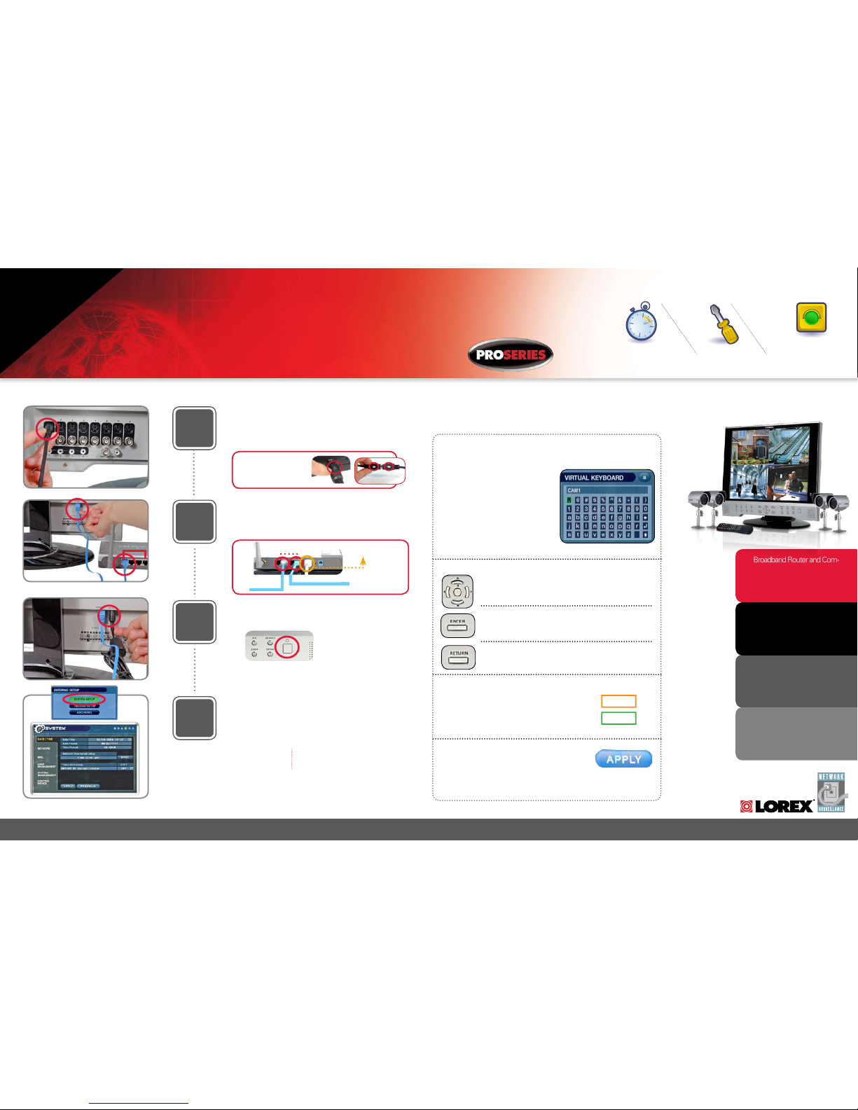
Connect Cameras to the Monitor:
Connect the first camera to the CH1 input. Follow the same steps
to connect the other cameras to the CH2, CH3, CH4 Video inputs*.
1
* Connect cameras to extension cables by aligning the arrows.
Plug in cameras and cables before mounting the cameras.
Connect Power Cable:
Connect one end of the Power cord to the monitor, the other end to
an electrical outlet. This unit powers ON once it is plugged in to the
power outlet.
MONITOR FRONT PANEL - POWER BUTTON
Turn ON** the LCD
Monitor Power
** After you see all four (4) camera images on your monitor screen,
remove the protective film from camera(s) and monitor screen.
4
Set the Time and Date***:
MAKE SURE THAT
THE DATE AND TIME
ARE SET PRIOR TO
RECORDING!
*** Note: If the Date/Time is
set into the past, a message
will appear warning that Overlapped date(s) will be erased.
Click the SETUP button from the front panel of the monitor (or the
remote control) to enter SYSTEM SETUP screen and press ENTER to go to MAIN MENU. From the MAIN MENU Scroll down to
SYSTEM and press ENTER to go to the DATE/TIME MENU. Press
ENTER while on DATE/TIME MENU to activate menu options.
For Lorex Client Software
Requirements, please refer to
page 8 of this guide.
For detailed setup information,
please refer to your User’s
Manual.
Broadband Router and Com-
puters are Required (for local
and remote monitoring), not
Included.
Congratulations! You have completed STEP 1 successfully. You can now
View, Record and Playback images on your Monitor.
NOTE: The arrow mark on top
of the flat side of the camera
and cable connectors should
face UP while inserting to the
Monitor.
LAN PORTS
Connect Ethernet Cable:
Connect one end of the ethernet cable to one of the router’s (not
included) LAN PORTS and the other end to Monitor’s Network Port
located at the back of the monitor. See picture below showing a
generic LAN/WAN connection.
WAN (WIDE
AREA NETWORK)
LAN (LOCAL AREA NETWORK)
TO YOUR COMPUTER
TO YOUR MONITOR
BACK OF THE ROUTER
2
Virtual Keyboard Control:
The Virtual Keyboard control becomes
available when keyboard input (A~Z, 0~9)
is needed for entering information such as
Names, Network Information, etc.
• Navigate using the arrow keys on the
Front Panel or Remote Control.
• Use the ENTER key to choose the letters
and numbers.
• Select the APPLY button once the setup is
completed.
Monitor Menu Navigation Controls:
Navigation Controls:
Move UP/DOWN/LEFT/RIGHT
Enter Button - Press this button to select and change the values in a
menu option
Return Button - Complete modifications of a menu option; exit a
menu
Active Option Indicator:
Orange Highlight - Indicates that the option is in active
editing mode.
Green Highlight - Indicates that the option is available for
editing. Once the option is highlighted, press the ENTER
key to edit the option (hightlight changes to Orange).
NOTE: Once changes have been made, select the APPLY
button at the bottom of the screen, and press the ENTER
button on the front panel or remote control. Changes will be
saved at this time - exiting the menu without applying the
changes will result in the changes being lost.
Apply:
SYSTEM NAVIGATION CONTROLS:
3
Model numbers referenced in
this document represents the
difference in the size of the LCD
monitor being either 17 or 19”
STEP 1
Page 2
ww w. lo re xc ct v. co m
SG19LD800/SG17LD800/400 Series Quick Start Guide_R1 Page 2
SET UP LOCAL VIEWING ON YOUR PC
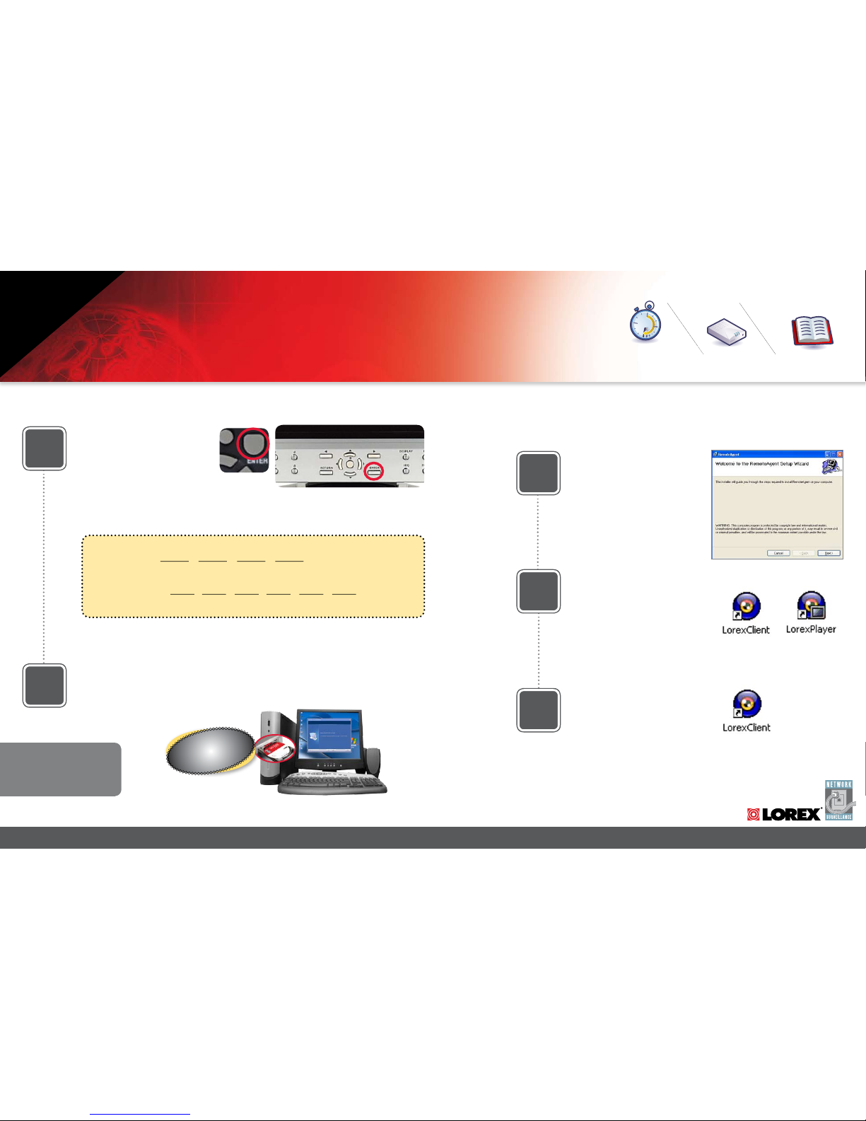
1
Retrieve System Information:
To retrieve the System Information,
press the ENTER button on the Remote
Control (ensure batteries are inserted)
(OR) Press the ENTER button on the
front panel of the Monitor (please check
the user’s manual for MENU steps).
Record the IP and MAC Addresses in the section below:
Install Software:
(on your Local Computer)
2
Insert the Lorex Client Software CD
into your local computer’s CD ROM
drive and proceed with installation.
3
Lorex Client Software:
(on your Local Computer)
Follow the installation screens to
complete Lorex Client Software installation.
Lorex Client Software:
(on your Local Computer)
4
Close the CD Menu Screen. A Lorex
Client icon and a Lorex Player icon
will appear on your desktop.
Run the Lorex Client Software:
(on your Local Computer)
5
Double-click the Lorex Client software
icon on your desktop to run the program.
MONITOR FRONT PANEL - ENTER BUTTON
REMOTE CONTROL
COMPUTER - NOT INCLUDED
IP ADDRESS : . . .
MAC ADDRESS : : : : : :
(needed to regis ter for DDNS)
On your
Local Computer
Router
Hi Speed
over 60 minutes
Time Skills - Intermediate
Plug & Play connectors,
On screen set up
Under 30 Minutes*
* Installation time may vary based
on application
Hi Speed
over 60 minutes
Hardware
Computer & Router*
Your Observation System must be connected to a Router prior to powering it ON
* Minimum System Requirement: Windows XP, Pentium IV, 256MB Ram
(512MB Recommended), 200MB Storage, Internet, DSL or Cable Modem
For Lorex Client Software
Requirements, please refer
to page 8 of this guide.
BASIC INSTALLATION GUIDE
STEP 2
Page 3
H O M E & BU S I N E S S S EC U R I T Y
ww w. lo re xc ct v. co m
SG19LD800/SG17LD800400 Series Quick Start Guide_R1 Page 3
SET UP LOCAL VIEWING ON YOUR PC
System
192.168.0.150
6100
ADMIN
****
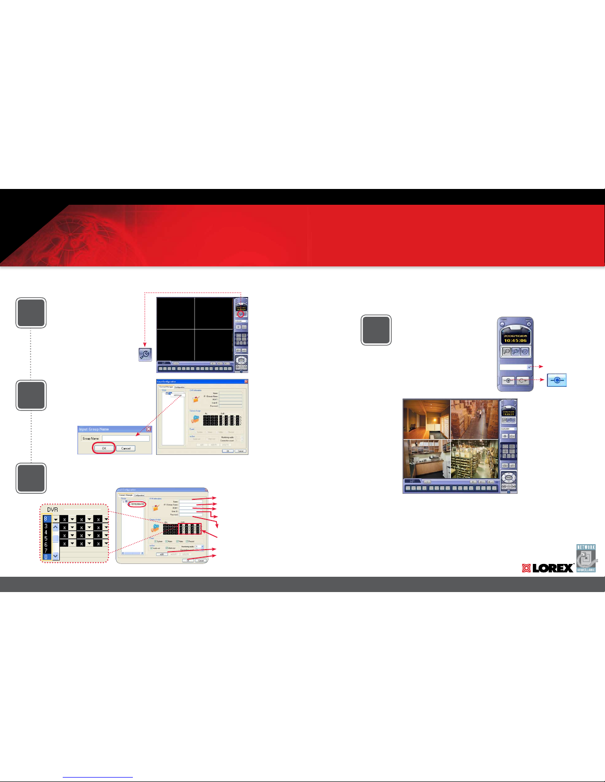
6
Set-up:
(on your Local Computer)
Click the Setup icon from the Lorex
Client Software Screen
Add ‘Group’:
(on your Local Computer)
7
Click on the SITE listing on the Left Panel,
and Right Click to ‘ADD GROUP’.
Enter a name for the GROUP, and click OK.
Enter Setup Information:
(on your Local Computer)
8
Select the GROUP you created and
enter SETUP information.
Lorex Client Software - Local
Configuration:
(on your Local Computer)
From the Lorex Client Software - Local
Configuration screen (as shown in Step
7), select the new Group you created
using the drop down menu (1) and press
the CONNECT button (2) to connect to
the LOCAL LIVE site.
SET-UP BUTTON
Basic Installation Guide
CONNECT BUTTON
1
2
9
7
8
1. Enter a Name for the System
2. Enter the IP Address recorded in Step 2-1
3. Enter the DVR/Monitor TCP/IP port (6100 by default)
4. Enter the User ID (ADMIN by default), max. 5
characters
5. Enter the Admin Password (1234 by default)
* User ID and Password are case sensitive
6. Add cameras using the dropdown menus to assign
camera positions
7. Click ADD to add the System Location
8. Click OK
1
2
3
4
5
6
6
Camera Selection Dropdown Menu
LOCAL LIVE SITE
OFFICE
STEP 2
Continued
Page 4

ww w. lo re xc ct v. co m
SG19LD800/SG17LD800/400 Series Quick Start Guide_R1 Page 4
1
Port Forward Your Router:
Port forward your router first before proceeding with the set-up (you must forward
web port 80 and TCP/IP Port 6100).
All routers are different. To port forward your router, please refer to your router’s
user’s manual.
A Router Configuration Guide is available on your Lorex Client Software CD and also
on our website in the Consumer Guide’s section.
DDNS Set-up:
2
Open your web browser (Internet Explorer by default) and enter
http://ddns.strategicvista.net in the address
bar.
Create Account:
3
From the http://ddns.strategicvista.net
website, click the CREATE ACCOUNT
option.
4
Complete New Account
Information:
1. FOR PRODUCT LICENSE select the
SG17LD804-161 option from the drop
down menu.
2. FOR PRODUCT CODE enter the
Monitor’s MAC address (recorded in
step 2, section 1).
3. FOR URL REQUEST enter a unique
URL name (e.g. tomsmith1). Note: URL
name should not be more than 15 characters.
Registration Email:
5
An automated REGISTRATION CONFIRMATION EMAIL will be sent to your
email. Print and Save this confirmation.
You will need this information to access
your System remotely.
Enter DDNS Set-up on your
Monitor:
6
Enter DDNS SET option on your monitor
by pressing the SETUP button on the
front panel of your monitor (or Remote
Control). Select the SYSTEM SETUP and
press ENTER. Scroll down to SYSTEM
and press ENTER. Scroll down to NETWORK option and press ENTER.
SET UP INTERNET REMOTE SECURITY
MONITORING
http://ddns.strategicvista.net
Create Account
1
2
3
Service Pro vider: dns1.strateg icvista.net
Domain Name : tomsmith.strategi cvista.net
User ID: to msmith1
Password: ( your password)
MONITOR FRONT PANEL - SETUP BUTTON
Hi Speed
over 60 minutes
Time Hardware Skills - Advanced
60 Minutes
Computer & Router*
Basic Computer Skills,
Router Port Forwarding
* Installation time may vary based
on application
Hi Speed
over 60 minutes
* Minimum System Requirement: Windows XP, Pentium IV, 256MB Ram
(512MB Recommended), 200MB Storage, Internet, DSL or Cable Modem
REMOTE VIEWING INSTALLATION GUIDE
STEP 3
Page 5

H O M E & BU S I N E S S S EC U R I T Y
ww w. lo re xc ct v. co m
SG19LD800/SG17LD800400 Series Quick Start Guide_R1 Page 5
7
Enable DDNS Settings:
Set the DDNS Settings:
8
1. Scroll down to the DDNS SERVER within the
NETWORK menu and press ENTER.
2. Enter the USER ID sent to you in the
REGISTRATION CONFIRMATION EMAIL.
3. Enter the DOMAIN NAME sent to you in the
REGISTRATION CONFIRMATION EMAIL
(i.e.tomsmith.strategicvista.net) leaving out the
.strategicvista.net part of the URL.
4. Enter your PASSWORD (1234 by default).
5. Click the DDNS Status button - A SUCCESS
message will appear if the settings are correct.
6. Scroll to OK button and press ENTER to accept.
7. On the SYSTEM menu screen scroll down to APPLY
and press ENTER.
8. The system will now ask you to RESTART.
Click OK.
9
10
11
12
On the NETWORK menu, use the
DOWN arrow key to navigate to
DDNS. Highlight DDNS checkbox
by pressing ENTER and press the
UP arrow key to put a check mark
in the DDNS checkbox. Press
ENTER to accept settings.
COMPUTER - NOT INCLUDED
Install Software:
(on your Remote Computer*)
Insert the Lorex Client Software CD into
your remote computer’s CD ROM drive
and proceed with installation.
Lorex Client Software:
(on your Remote Computer*)
Follow the installation screens to
complete Lorex Client Software
installation.
Lorex Client Software:
(on your Remote Computer*)
Close the CD Menu Screen. A Lorex
Client icon and a Lorex Player icon will
appear on your desktop.
Run the Lorex Client Software:
(on your Remote Computer*)
Double-click the Lorex Client icon on
your desktop to run the program.
SET UP INTERNET REMOTE SECURITY MONITORING
On your
Remote Computer*
For Lorex Client Application
Software Requirements, please
refer to page 8 of this guide.
*For viewing your system from a remote location
tomsmith1
tomsmith
****
SUCCESS
STEP 3
Continued
Page 6

H O M E & BU S I N E S S S EC U R I T Y
ww w. lo re xc ct v. co m
SG19LD800/SG17LD800400 Series Quick Start Guide_R1 Page 6
1. Enter a Name for the System
2. Enter the DDNS DOMAIN NAME from the
Registration Email sent to you.
3. Enter the DVR/Monitor TCP/IP port (6100 by default)
4. Enter the User ID (ADMIN by default), max. 5
characters
5. Enter the Admin Password (1234 by default)
* User ID and Password are case sensitive
6. Add cameras using the dropdown menus to assign
camera positions
7. Click ADD to add the System Location
8. Click OK
1
3
4
5
6
14
13
16
15
Set-up:
(on your Remote Computer*)
Click the Setup icon from the Lorex
Client Software Screen
Add ‘Group’:
(on your Remote Computer*)
Click on the SITE listing on the Left
Panel, and Right Click to ‘ADD GROUP’.
Enter a name for the GROUP, and click
OK.
Enter Setup Information:
(on your Remote Computer*)
SET-UP BUTTON
Lorex Client Software - Local
Configuration:
(on your Remote Computer*)
From the Lorex Client Software - Local
Configuration screen (as shown in Step
13), select the new Group you created
using the drop down menu (1) and press
the CONNECT button (2) to connect to
the REMOTE* LIVE site.
CONNECT BUTTON
1
2
SET UP INTERNET REMOTE SECURITY MONITORING
7
8
6
Camera Selection Dropdown Menu
System
tomsmith.strategicvista.net
6100
ADMIN
****
2
REMOTE* LIVE SITE
*For viewing your system from a remote location
For other remote access viewing
features, please consult the Lorex
Client Software Manual.
STEP 3
Continued
OFFICE
Page 7

SG19LD800/SG17LD800/400 Series Quick Start Guide_R1 Page 7
ww w. lo re xc ct v. co m
MONITOR POWER SAVING TIP
To extend the life of your monitor, it is highly recommended that you take advantage
of the AUTO BRIGHTNESS & MAIN DISPLAY OFF features. Enabling these features will
save power by automatically dimming your monitor when not in use or turning the
monitor OFF during off-peak hours (Note: recording will never be turned OFF or affected
by these settings). Follow these simple instructions to extend the life of your monitor.
1
System Setup Menu:
Click the SETUP button
from the front panel
of the monitor (or the
remote control) to
enter SYSTEM SETUP
screen and select the
SYSTEM SETUP and
ENTER to go to the
MAIN MENU.
MONITOR FRONT PANEL - SETUP BUTTON
2
Main Menu:
In the MAIN MENU
screen, select DISPLAY
and press ENTER. Use
the down arrow key
and select SCREEN
SAVER menu and
ENTER to activate the
SCREEN SAVER menu
options.
3
Screen Saver Menu:
Auto Brightness:
Adjust Brightness by
highlighting and pressing ENTER, then use the
DOWN and UP arrow keys
to adjust time.Press ENTER
when complete.
Main Display OFF:
Enable this option by selecting ON. Set time on the
‘FROM’ and ‘TO’ fields to determine the times you want
the Main Display OFF.
Page 8

SG19LD800/SG17LD800/400 Series Quick Start Guide_R1 Page 8
ww w. lo re xc ct v. co m
IT’S ALL ON THE WEB
ww w .l o re x cc t v. c om
Product Information Software/Hardware
Updates & Ugrades
Product Documentation
Specification Sheet
User’s Manual
Lorex Client Software Manual
Quick Start Guide
Portforwarding Guide
Basics of Remote Video
Access Guide
For detailed setup information, please refer to your User’s Manual. For
additional information about determining your IP address, configuring your
router, and port forwarding, please visit our website www.lorexcctv.com and
click Consumer Guides Section or view guides from the Lorex Client Software
CD included with your system.
Toll Free Technical Support - North America: 1-888-42 LOREX (1-888-425-6739)
Toll Free Technical Support - International (outside of North America): +800-425-6739-0
Lorex International Website - www.lorexinternational.com
Email Support: support@lorexcorp.com
LOREX CLIENT SOFTWARE REQUIREMENTS:
The Lorex Cli ent software (includ ed with the Observa tion System) has the following installa tion requirements.
Minimum System Requirements:
Operating Sys tem: Windows 2000, Windows XP Home Edition, Wi ndows XP Professiona l
Processor: Pentium 4 - 1 .5 GHz Processor (or equivalent)
Memory: 256 MB RAM
Hard Drive: 50 MB - Install ation space required . * Additional Hard Drive space require d for recording.
Recorded file size w ill vary depending on recording quality settings
Recommended System Requirements:
Operating Sys tem: Windows XP Home Editio n
Windows XP Professi onal
Processor: Pentium 4 / 3 GHz Processor (or e quivalent)
Memory: 1024 MB RAM
Hard Drive: 50 MB - Install ation space required
* Additional Hard D rive space required for recording. Reco rded file size will vary depending
on recording qualit y settings
Please refer to the Lorex Client Software User Guide included with your Observation System for further
details. Visi t the Lorex support website at http://w ww.lorexcctv.com for information on Win dows Vista
compatibility .
 Loading...