

Page 1

Universal VCR Controller
MODEL RA 110
PROGRAMMING PROCEDURE
1) Press the power switch to turn on the RA 110
2) Press the SET button, the “SET” LED will turn on and flash
3) Press the REC button, the “REC” LED will turn on and flash
4) While the “SET/REC” LED’s are flashing, press the recording button on the VCR’s remote
control to aim at the RX sensor.
5) The “SET/REC” LED will turn off the confirm completion of record signal programming
6) Press the “SET” button, then press the “STOP” button. Both the “SET/STOP” LED will flash
7) While the “SET/STOP” LED’s are flashing, press the stop button on the VCR’s remote control,
and aim it at the RX sensor
8) The “SET/STOP” LED will turn off to confirm the completion of the “STOP” signal
programming. The programming procedure is now complete.
SPECIFICATIONS
Power Source DC 12V 500mA AC adapter
Recording Time 10 - 90 seconds adjustable
TX Sensor Range 5M 45
External Sensor Cable 1 metre
Camera Input 4 Pin DIN connector
A/V output 4 Pin DIN connector
Video Output Level 1V p-p 75ohms
Audio Output Level 1V p-p
Operating Temperature -10
C ~ +50 C
Dimensions 143(W) x 35(H) x 111(D)mm
Weight 200g
INSTALLATION TIP
After you program the RA 110, please confirm the programming with the following
procedure:
(A) The distance between the RA 110 and the VCR should be about 1 metre, and aimed
directly at your VCR.
(B) Turn your VCR “ON” and press the “REC” button on the RA 110. Your VCR should go
into the recording mode.
(C) If the VCR does not go into the recording mode, please re-program the RA 110 again.
(D) Check the “STOP” button on the RA 110, and follow the above procedure.
Please Note: The RA 110 requires its own power supply for proper operation. Please power
up unit with the supplied adapter.
The Universal VCR Controller is a perfect compliment to your OS 100 or OS 300 Motion
Sensor Video Security Camera. It “learns” the remote control commands to control your VCR,
and will record any activity picked up by your video security camera for playback at any time.
Contents
• VCR Control Unit
• Power adapter 110V AC / 12V DC (500mA)
• RCA cable
• External IR sender (with sensor cable)
• 4 Pin DIN cable (1 metre)
• Adhesive tape
• Compatible with most makes or models of consumer VCR’s which can be controlled via IR
remote control
• “Learns” RECORD and STOP commands of remote control for consumer VCR via front panel
IR sensor
• “Plug n’Play” connection with any Home Sentinel TV observation system, and detects alarm
signal and activates VCR commands
• Sends RECORD and STOP commands by a rear panel infrared sender to activate VCR
• Programmable recording duration from 10~90 seconds
• Additional external IR sender with 1 metre cable included
• Separate RCA audio/video outputs for direct connection to consumer VCR
INTRODUCTION
FEATURES
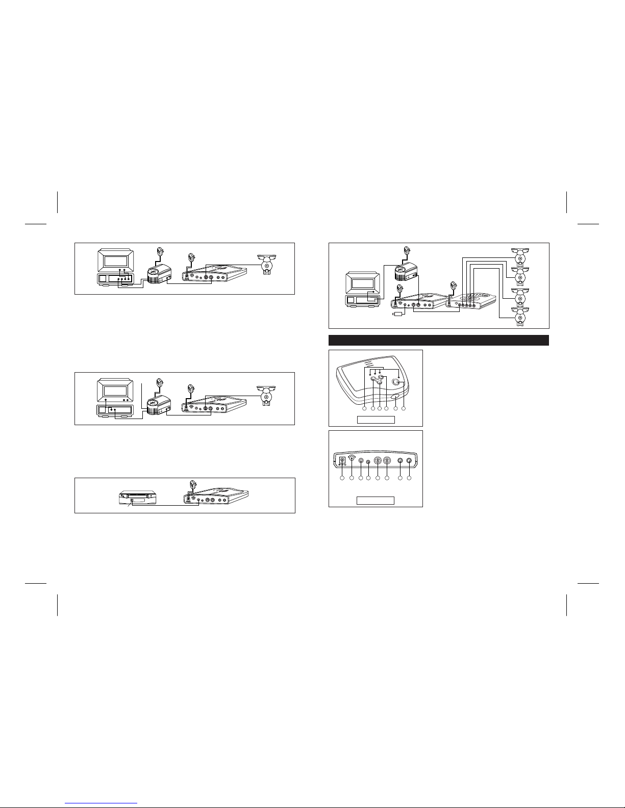
Connection to VCR and TV using RCA patch cord (A/V connection)
1) Connect the plug at the end of the OS100 or OS300 camera cable to the camera input jack
on the rear of the VCR Control unit.
2) Connect the A/V output jack on the VCR Controller to the camera input on the OS100 or
OS300 RF Control Unit, using the DIN patch cord supplied.
3) Connect the output audio and video jacks on the VCR Controller unit to the audio and video
inputs, using the supplied RCA patch cords.
4) Connect the output audio and video jacks on the VCR to the input audio and video jack on
the TV, using an RCA patch cord.
5) Plug in all units
INSTALLATION
Page 2
1) Power switch : To turn the power On/Off.
2) Set button : To activate programming function.
3) Record button : To select “Record” signal
programming function or manually activates the
VCR in recording mode
4) Stop button : To select “Stop” signal
programming function or manually stop the VCR.
5) RX Sensor : To receive Rec/Stop signals from the
VCR’s remote control.
6) LED : Function indicator for Rec, Stop, Set and
Power.
7) DC Input jack : Input terminal for the power, from
the 12V AC adapter
8) Time control knob : To adjust the recording
duration from 10~90 seconds
9) External TX output jack : To output VCR
commands for external infrared sensoring
Optional Connection with External Sensor cable
If the built-in TX sensor cannot be used to activate your VCR, then an external sensor jack can
be used to activate your VCR.
1) Connect the supplied sensor cable to the external sensor jack and apply the TX sensor to the
front of the VCR’s IR receiver.
2) Plug unit in [Note; Sends VCR commands (REC & STOP) from the Controller unit back to the
VCR, via infrared signaling.]
Connection with 4 camera switcher
1) Connect the 4 Pin Din cable from the camera input on the control unit (RA 110) to the output
jack on the 4 camera switcher (SB 100).
2) Connect the RF modulator box to the A/V output on the RA 110 unit
3) Connect the RF cable from the output of the modulator to the input on the TV or VCR.
4) Connect all the AC adapters on the modulator, control unit RA 110, and 4 camera switcher
SB 100, and plug units into AC power.
Connection to VCR and TV using CATV patch cord
1) Connect the plug at the end of the OS100/300 camera cable to the camera input on the rear
of the VCR Control unit.
2) Connect the A/V output jack on the VCR Controller to the Camera input on the RF Control
Unit using the supplied DIN cable
3) Connect the CATV/Antenna signal input to the RF input of the RF Control unit.
4) Connect the RF output from the RF control unit to the CATV input on the VCR, using CATV
connection cord
5) Connect the CATV output on the VCR to the CATV input on the TV using the CATV
connection cord
6) Plug in all units
REC
ST
OP
SET
POWER
DC 10V
VIDEO OUT
AUDIO OUT
REMOTE OUT
T
O CAMERA
A/V OUT
TX
TIME
MIN
MAX
REC
ST
OP
SET
POWER
DC 10V
VIDEO OUT
AUDIO OUT
REMOTE OUT
T
O CAMERA
A/V OUT
TX
TIME
MIN
MAX
CCD CAMERA
VCR
TV
<RECORDING SYSTEM>
EXT. SENSOR
(TO VCR)
AC
ADAPTOR
RCA CABLE
CAMERA
4P DIN CABLE
(NOT SUPPLIED)
VIDEO
AUDIO
VIDEOAUDIOVIDEOAUDIO
IN
IN OUT
<VCR>
<RECORDING SYSTEM>
AC
ADAPTOR
(NOT SUPPLIED)
Adhesive Tape
SENSOR
STOP/EJECT
POWER
REC
REC
ST
OP
SET
POWER
DC 10V
VIDEO OUT
AUDIO OUT
REMOTE OUT
TO CAMERA
A/V OUT
TX
TIME
MIN
MAX
VCR
TV
<RECORDING SYSTEM>
EXT. SENSOR
(TO VCR)
AC
ADAPTOR
RF CABLE
(NOT SUPPLIED)
ANT
RF IN
RF OUT
CAMERA
AUDIO
VIDEO
OUT
TIME
MIN MAX
<MODULATOR UNIT>
CCD CAMERA
CCD CAMERA
CCD CAMERA
CCD CAMERA
<4CA SWITCHER UNIT>
DIN CABLE
<CAMERA UNIT>
DIN CABLE
C2
C3
C4
POWER
C1
AUT
O
SENSOR
DC 10V
AUT
O
TIME
C1
C2
C3
C4
OUT PUT
REC
ST
OP
SET
POWER
DC 10V
VIDEO OUT
AUDIO OUT
REMOTE OUT
T
O CAMERA
A/V OUT
TX
TIME
MIN
MAX
CCD CAMERA
<VCR>
<RF CONTROL UNIT>
<TV>
<VCR CONTROLLER>
RA 110
AC
ADAPTOR
AC
ADAPTOR
RCA PATCH CORD
DIN CABLE
CAMERA
DIN CABLE
VIDEO
AUDIO
VIDEOAUDIOVIDEOAUDIO
IN
IN OUT
CAMERA
AUDIO
VIDEO
OUT
TIME
MIN MAX
REC
ST
OP
SET
POWER
DC 10V
VIDEO OUT
AUDIO OUT
REMOTE OUT
T
O CAMERA
A/V OUT
TX
TIME
MIN
MAX
CCD CAMERA
<VCR>
<RF CONTROL UNIT>
<TV>
<VCR CONTROLLER>
RA 110
AC
ADAPTOR
AC
ADAPTOR
CATV INPUT
SIGNAL
CATV PATCH CORD
DIN CABLE
CAMERA
DIN CABLE
IN
RCA
CATV
OUT IN
CATV
CAMERA
AUDIO
VIDEO
OUT
TIME
MIN MAX
DESCRIPTION OF CONTROLS
12119
10
7
52 436 1
DC 10V
REMOTE OUT TO CAMERA A/V OUTTX
8
TIME
MIN MAX
REC
SET
STOP
POWER
Front view
12119
10
14
13
7
DC 10V
VIDEO OUT AUDIO OUT
REMOTE OUT TO CAMERA A/V OUTTX
8
TIME
MIN MAX
Rear view
10) TX Sensor : Emits Record/Stop commands to the VCR
11) Camera input : Connecting terminal for camera (4 Pin Din connector)
12) A/V output : Connecting terminal for RF modulator unit.
13) Video output : This terminal outputs a video signal from the camera
14) Audio output : This terminal outputs an audio signal from the camera
 Loading...