

Lorex QLR464, QLR460 SERIES Instruction Manual
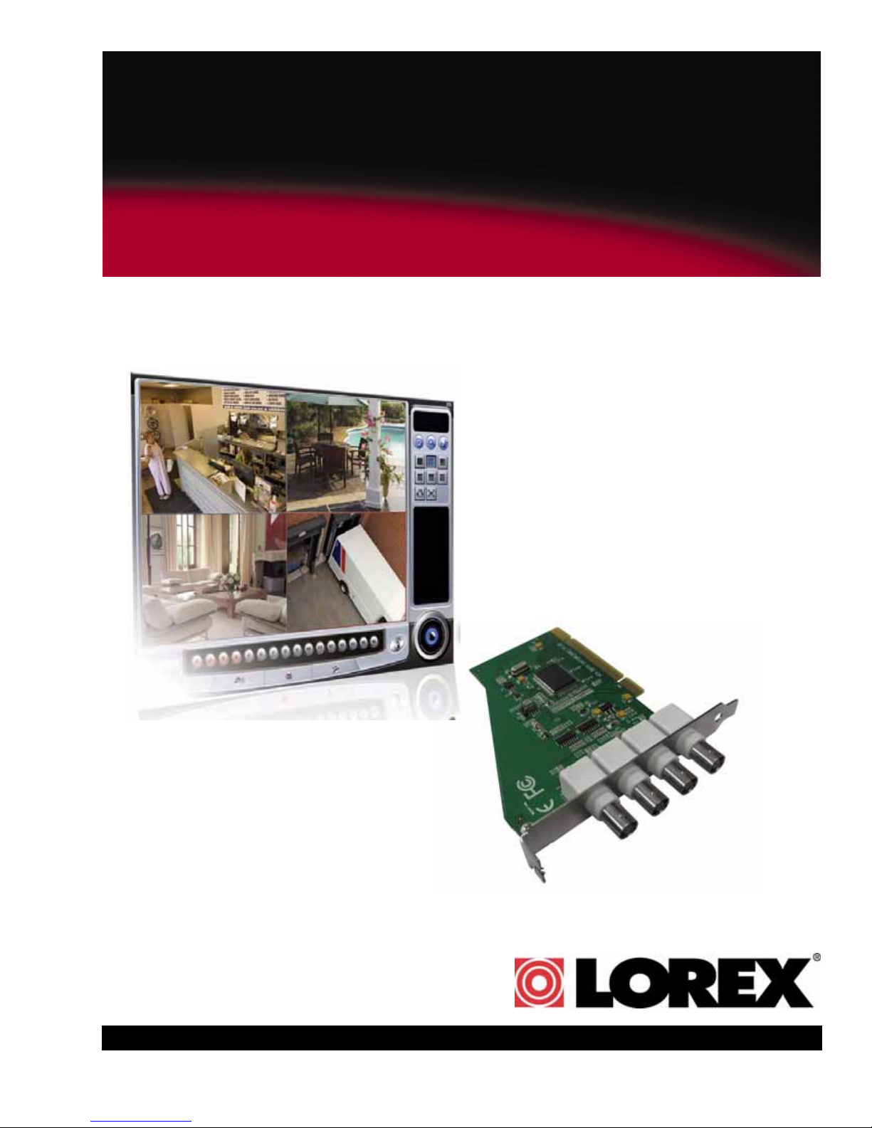
PCI CARD
DIGITAL VIDEO RECORDER
INSTRUCTION MANUAL
English Version 1.0
QLR460 SERIES
Copyright © 2010 Lorex Technology Inc.
www.lorexcctv.com
Thank you for purchasing this product. Lorex is committed to providing our customers
with a high quality, reliable security solution.
This manual refers to the following model(s):
• QLR460 (4-Channel)
For more information on this product, firmware updates, and accessory products, please
visit us at:
www.lorexcctv.com
CAUTION
RISK OF ELECTRIC SHOCK
DO NOT OPEN
CAUTION: TO REDUCE THE RISK OF ELECTRIC SHOCK DO NOT
REMOVE COVER. NO USER SERVICABLE PARTS INSIDE.
REFER SERVICING TO QUALIFIED SERVICE PERSONNEL.
The lightning flash symbol within an equilateral triangle is intended
to alert the user to the presence of uninsulated "dangerous voltage"
within the products ' enclosure that may be of sufficient magnitude
to constitute a risk of electric shock.
The exclamation point within an equilateral triangle is intended to
alert the user to the presence of important operating and
maintenance (servicing) instructions in the literature accompanying
the appliance.
WARNING: TO PREVENT FIRE OR SHOCK HAZARD, DO NOT
EXPOSE THIS UNIT TO RAIN OR MOISTURE.
CAUTION: TO PREVENT ELECTRIC SHOCK, MATCH WIDE BLADE
OF THE PLUG TO THE WIDE SLOT AND FULLY INSERT.

B E F O R E Y O U S T A R T
THIS PRODUCT MAY REQUIRE PROFESSIONAL INSTALLATION
LOREX IS COMMITTED TO FULFILLING YOUR SECURITY NEEDS
• We have developed user friendly products and documentation.
Please read the Quick Start Guide and User Manual before you
install this product.
• Consumer Guides and Video Tutorials are available on our web
site at www.lorexcctv.com/support
• If you require further installation assistance, please visit
www.lorexcctv.com/installation or contact a professional
installer.
• Please refer to the “Need Help” insert for technical support and
customer care information.
• Please note that once the components of this product have been
unsealed, you cannot return this product directly to the store
without the original packaging.
www.lorexcctv.com

AVANT DE
A N T E S D E
COMMENCER
CE PRODUIT POURRAIT EXIGER UNE
INSTALLATION PROFESSIONNELLE
LOREX S’ENGAGE À SATISFAIRE
VOS BESOINS SÉCURITAIRES
• Veuillez lire le guide de démarrage rapide et le
mode d’emploi avant d’installer ce produit.
• Les guides du consommateur et les séances
de tutorat vidéo sont disponibles sur l’Internet en
visitant www.lorexcctv.com/support
• Si vous avez besoin de l’aide pour l’installation,
E M P E Z A R
ESTE PRODUCTO PUEDE EXIGIR UNA
INSTALACIÓN PROFESIONAL
LOREX SE COMPROMETE A SATISFACER
SUS NECESIDADES EN SEGURIDAD
• Favor de leer la guía de instalación rápida y la
guía del usuario antes de instalar este producto.
• Puede conseguir las guías del consumidor y
los cursos en enseñanza video sobre el Internet
visitando www.lorexcctv.com/support
• Si necesita ayuda para la instalación, visite
veuillez visiter www.lorexcctv.com/installation
ou contactez un spécialiste en installation
• Veuillez référer à l’insert “Need Help” pour
ob¬tenir de l’information sur le service à la cli-
entèle et le support technique
• Veuillez constater qu’une fois que les
com¬posantes de ce produit ont été retirées de
l’emballage, vous ne pourrez plus retourner ce
produit directement au magasin.
www.lorexcctv.com/installation o contacte un
especialista en instalaciones
• Favor de referir al documento “Need Help” para
obtener información acerca del servicio al cliente
y al soporte técnico
• Favor de notar que una vez que los compo-
nentes de este producto han sido removidos del
embalaje, no podrá devolver este producto di-
rectamente a la tienda
w w w . l o r e x c c t v . c o m

NEED HELP?
CONTACT US FIRST
DO NOT R E T U R N THIS PRODUCT TO THE STORE
Please make sure to register your product at www.lorexcctv.com to receive product updates and information
3 EASY WAYS TO CONTACT US:
Online:
Pr od u ct S up p or t is a v ai la b le 2 4/ 7 i nc lu di n g pr od u ct
in fo r ma ti on , us er ma nu al s, q ui ck s t ar t up gu id es an d FAQ ’s
at w ww.lorexcct v.com/ suppo rt
To o rd er ac ce ss o ri es , v i si t
www.l orex cctv.com
By Email:
Te ch ni ca l S up po r t (f or te ch ni c al /i ns tal la ti o n is su es )
sup port@ lore xcorp.co m
Cu st o me r Ca r e (f or wa rr an ty an d ac c es so r y sa le s )
cus tomer servic e@lor exco rp.com
Cu st o me r Fe e db ac k
inf o@lor exco rp. com
By Phone:
NORTH AMERICA:
CUSTOMER SERVICE: 1-888-425-6739 (1-888-42-LOREX)
TECH SUPPORT: 1-877-755-6739 (1-877-75-LOREX)
MEXICO: 1-800-514-6739
INTERNATIONAL: +800-425-6739-0
(Ex amp le: Fr om the UK , dia l 0 0 i nst ead of +)
Ve rs i o n 7 - No v 2 6 2 0 0 9

NECESITA AYUDA
VOUS AVEZ BESOIN
D’AIDE?
COMUNÍQUESE PRIMERO
CON NOSOTROS
NO DEVUELVA ESTE PRODUCTO A LA TIENDA
Cerciór ese de p or favor colocar su prod ucto en www.
lorexcc tv.c om/regis tration para rec ibir act ualiz aciones y l a inform ación de l produc to
3 manera s sencillas de c omunicarse
co n nosotros:
www
En línea:
apoyo al producto disponible 24/7 incluyendo información del product o, manuales par a el usuario, g uías
de inicio rápido y preguntas más frecuentes en
www.lorexcctv.com/support
Para colocar pedid os de accesorios, visite
www.lorexcctv.com
CONTACTEZ-NOUS
D’ABORD
NE RETOURNEZ PAS CE PRODUIT AU MAGASIN
Veu illez ve iller à enregist rer votr e produi t à w ww.
lorexcc tv.c om/regis tration pour rec evoir de s mis es à
jour et l’infor mation d e produi t
3 façons faciles de nous contacter:
www
En ligne:
le support des pro duits est disponible 24 heures sur 24, 7
jours sur 7, y compris les informations sur les produits, les
guides de l’utilis ateur, les guides de démarrage r apide et
les foires à questions
www.lorexcctv.com/support
Pour commander des accessoires, v isitez
www.lorexcctv.com
Por Correo Electrónico:
soporte técnico (p ara asuntos técnicos/la instalación)
support@lorexcorp.com
O
servicio al cliente (respecto a la garantía y a l a venta
de accesorios)
customerservice@lorexcorp.com
Comentarios de cli ente
info@lorexcorp.com
Por Teléfono:
L’AMÉRIQUE DU NORD:
ATENCIÓN AL CLIENTE: 1-888-425-6739 (1-888-42-LOREX)
SOPORTE TÉCNICO: 1-877-755-6739 (1-877-75-LOREX)
MEXICO: 1-800-514-6739
INTERNACIONAL: +800-425-6739-0
(Ejemplo: Desde el Reino Unido, marque el 00 en lugar del +)
sus opiniones son bienvenidas en
info@lorexcorp.com
para colocar pedidos de accesorios, visite
Par Courriel:
support technique (pour les questions techniques et
d’installation) support@lorexcorp.com
OU
service à la clientèle (pour les questions de gar antie
et les ventes d’ac cessoires)
customerservice@lorexcorp.com
Commentaires des c lients
info@lorexcorp.com
Par Téléphone:
NORTE AMÉRICA:
SERVICE À LA CLIENTÈLE: 1-888-425-6739 (1-888-42-LOREX)
SUPPORT TECHNIQUE: 1-877-755-6739 (1-877-75-LOREX)
MEXICO: 1-800-514-6739
INTERNATIONAL: +800-425-6739-0
(Exemple: À partir du Royaume-Uni, composez 00 au lieu de +)
nous serions heureux de recevoir vos
commentaires à info@lorexcorp.com pour
commander des accessoires, visitez
www.lorexcctv.com
www.lorexcctv.com
Ve rs i o n 7 - No v 2 6 2 0 0 9
Important Safeguards
In addition to the careful attention devoted to quality standards in the manufacturing process of
your video product, safety is a major factor in the design of every instrument. However, safety is
your responsibility too. This sheet lists important information that will help to assure your
enjoyment and proper use of the video product and accessory equipment. Please read them
carefully before operating and using your video product.
Installation
1. Read and Follow Instructions - All the safety and
operating instructions should be read before the
video product is operated. Follow all operating
instructions.
2. Retain Instructions - The safety and operating
instructions should be retained for future reference.
3. Heed Warnings - Comply with all warnings on the
video product and in the operating instructions.
4. Polarization - Do not defeat the
safety purpose of the polarized or
grounding-type plug.
A polarized plug has two blades
with one wider than the other.
A grounding type plug has two
blades and a third grounding prong.
The wide blade or the third prong
are provided for your safety.
If the provided plug does not fit into your outlet,
consult an electrician for replacement of the
obsolete outlet.
5. Power Sources - This video product should be
operated only from the type of power source
indicated on the marking label. If you are not sure of
the type of power supply to your location, consult
your video dealer or local power company. For video
products intended to operate from battery power, or
other sources, refer to the operating instructions.
6. Overloading - Do not overload wall outlets of
extension cords as this can result in the risk of fire
or electric shock. Overloaded AC outlets, extension
cords, frayed power cords, damaged or cracked wire
insulation, and broken plugs are dangerous. They
may result in a shock or fire hazard. Periodically
examine the cord, and if its appearance indicates
damage or deteriorated insulation, have it replaced
by your service technician.
7. Power Cord Protection - Power supply cords should
be routed so that they are not likely to be walked on
or pinched by items placed upon or against them,
paying particular attention to cords at plugs,
convenience receptacles, and the point where they
exit from the video product.
8. Ventilation - Slots and openings in the case are
provided for ventilation to ensure reliable operation
of the video product and to protect it from
overheating. These openings must not be blocked or
covered. The openings should never be blocked by
placing the video equipment on a bed, sofa, rug, or
other similar surface. This video product should
never be placed near or over a radiator or heat
register. This video product should not be placed in a
built-in installation such as a bookcase or rack
unless proper ventilation is provided or the video
product manufacturer’s instructions have been
followed.
9. Attachments - Do not use attachments unless
recommended by the video product manufacturer as
they may cause a hazard.
10. Camera Extension Cables – Check the rating of
your extension cable(s) to verify compliance with
your local authority regulations prior to installation.
11. Water and Moisture - Do not use this video product
near water. For example, near a bath tub, wash
bowl, kitchen sink or laundry tub, in a wet
basement, near a swimming pool and the like.
Caution
operated equipment or accessories connected to
this unit should bear the UL listing mark of CSA
certification mark on the accessory itself and should
not be modified so as to defeat the safety features.
This will help avoid any potential hazard from
electrical shock or fire. If in doubt, contact qualified
service personnel.
12. Accessories - Do not place this
video equipment on an unstable
cart, stand, tripod, or table. The
video equipment may fall, causing
serious damage to the video
product. Use this video product
only with a cart, stand, tripod,
bracket, or table recommended by the
manufacturer or sold with the video product. Any
mounting of the product should follow the
manufacturer’s instructions and use a mounting
accessory recommended by the manufacturer.
: Maintain electrical safety. Powerline
iii

Service
13. Servicing - Do not attempt to service this video
equipment yourself as opening or removing covers
may expose you to dangerous voltage or other
hazards. Refer all servicing to qualified service
personnel.
14. Conditions Requiring Service - Unplug this video
product from the wall outlet and refer servicing to
qualified service personnel under the following
conditions:
• When the power supply cord or plug is damaged.
• If liquid has been spilled or objects have fallen into
the video product.
• If the video product has been exposed to rain or
water.
• If the video product does not operate normally by
following the operating instructions. Adjust only
those controls that are covered by the operating
instructions. Improper adjustment of other controls
may result in damage and will often require
extensive work by a qualified technician to restore
the video product to its normal operation.
• If the video product has been dropped or the cabinet
has been damaged.
• When the video product exhibits a distinct change
in performance. This indicates a need for service.
Use
19. Cleaning - Unplug the video product from the wall
outlet before cleaning. Do not use liquid cleaners or
aerosol cleaners. Use a damp cloth for cleaning.
20. Product and Cart Combination - Video and cart
combination should be moved with care. Quick
stops, excessive force, and uneven surfaces may
cause the video product and car combination to
overturn.
21. Object and Liquid Entry - Never push objects for
any kind into this video product through openings as
they may touch dangerous voltage points or
“short-out” parts that could result in a fire or
electric shock. Never spill liquid of any kind on the
video product.
22. Lightning - For added protection for this video
product during a lightning storm, or when it is left
unattended and unused for long periods of time,
unplug it from the wall outlet and disconnect the
antenna or cable system. This will prevent damage
to the video product due to lightning and power line
surges.
15. Replacement Parts - When replacement parts are
required, have the service technician verify that the
replacements used have the same safety
characteristics as the original parts. Use of
replacements specified by the video product
manufacturer can prevent fire, electric shock or
other hazards.
16. Safety Check - Upon completion of any service or
repairs to this video product, ask the service
technician to perform safety checks recommended
by the manufacturer to determine that the video
product is in safe operating condition.
17. Wall or Ceiling Mounting - The cameras provided
with this system should be mounted to a wall or
ceiling only as instructed in this guide, using the
provided mounting brackets.
18. Heat - The product should be situated away from
heat sources such as radiators, heat registers,
stoves, or other products (including amplifiers) that
produce heat.
General Precautions
iv

General Precautions
FCC CLASS B NOTICE
NOTE
This equipment has been tested and found to comply with the limits for a Class B digital device, pursuant to
Part 15 of the FCC Rules. These limits are designed to provide reasonable protection against harmful
interference in a residential installation. This equipment generates, uses, and can radiate radio frequency
energy and, if not in-stalled and used in accordance with the instruction, may cause harmful interference to
radio communications.
However, there is no guarantee that interference will not occur in a particular installation. If this equipment
does cause harmful interference to radio or television reception (which can be determined by turning the
equipment on and off), the user is encouraged to try to correct the interference by one or more of the following
measures:
• Reorient or relocate the receiving antenna
• Increase the separation between the equipment and receiver
• Connect the equipment into an outlet on a circuit different from that to which the receiver is
connnected.
• Consult the dealer or an experienced radio or television technician for assistance
www.lorexcctv.com
1. All warnings and instructions in this manual should be followed.
2. Remove the plug from the outlet before cleaning. Do not use liquid aerosol detergents.
3. Do not use this unit in humid or wet places.
4. Keep enough space around the unit for ventilation. Slots and openings in the storage cabinet
should not be blocked.
5. During lightning storms, or when the unit is not used for a long time, disconnect the power
supply, antenna, and cables to protect the unit from electrical surge.
This equipment has been certified and found to comply with the limits regulated by FCC, EMC, and
LVD. Therefore, it is designated to provide reasonable protection against interference and will not
cause interference with other appliance usage.
However, it is imperative that the user follows the guidelines in this manual to avoid improper
usage which may result in damage to the unit, electrical shock and fire hazard injury.
In order to improve the feature functions and quality of this product, the specifications are subject
to change without notice from time to time.
v
Features
• Digital Recording of live video to PC’s hard drive
• Can also record on an external hard drive (not included)
• Internet Remote Monitoring
• H.264 video compression maximizes recording time
• View up to four locations simultaneously
• PC compatible with Windows XP™, Vista™ and 7
• Viewing options: Quad / Full Screen / Sequencing
• Easy search and playback of digitally recorded video
• Password security protection
• Free Lorex DDNS (Dynamic Domain Name System) service keeps you connected anywhere
all the time
• Lorex DDNS keeps you connected at all times
• Email alerts notify you when events occur
• WatchDog feature assures stable recording
• 2-Audio channel inputs
• Web browser client software
vi

TABLE OF CONTENTS
Getting Started . . . . . . . . . . . . . . . . . . . . . . . . . . . . . . . . . . . . . . . . . . . . . . . . . 1
Installing The QLR460 Series PCI Card . . . . . . . . . . . . . . . . . . . . . . . . . . . . . 2
Before You Start . . . . . . . . . . . . . . . . . . . . . . . . . . . . . . . . . . . . . . . . . . . . . . . . . . . . . . . . . 2
Prerequisites & Hardware Requirements . . . . . . . . . . . . . . . . . . . . . . . . . . . . . . . . . . . . 2
Minimum System Requirements . . . . . . . . . . . . . . . . . . . . . . . . . . . . . . . . . . . . . . . . . . . . . . . . . . . . . . . . . . . . . . . . . 2
Installing The QLR460 Series Surveillance Card . . . . . . . . . . . . . . . . . . . . . . . . . . . . . . 3
Installing the Cameras . . . . . . . . . . . . . . . . . . . . . . . . . . . . . . . . . . . . . . . . . . . . . . . . . . . 4
Installing the Software . . . . . . . . . . . . . . . . . . . . . . . . . . . . . . . . . . . . . . . . . . 5
Installing Vista Pro 6 Server (Local Viewing) . . . . . . . . . . . . . . . . . . . . . . . . . . . . . . . . . . . . . . . . . . . . . . . 5
Installing Vista Pro 6 Client (Remote Viewing) . . . . . . . . . . . . . . . . . . . . . . . . . . . . . . . . . . . . . . . . . . . . . . 5
Selecting a save directory and Allocating Storage Space . . . . . . . . . . . . . . . . . . . . . . . . . . . . . . . . . . . . . 7
Installing extra software . . . . . . . . . . . . . . . . . . . . . . . . . . . . . . . . . . . . . . . . . . . . . . . . . . . . . . . . . . . . . . . 7
Hard Drive Setup Scenarios . . . . . . . . . . . . . . . . . . . . . . . . . . . . . . . . . . . . . . . . . . . . . . . . . . . . . . . . . . . . . 8
A hard drive with a recovery partition (ie. C drive and D drive with Recovery Software) . . . . . . . . . . . . . . . . . . . .8
A single hard drive (ie. C drive only) . . . . . . . . . . . . . . . . . . . . . . . . . . . . . . . . . . . . . . . . . . . . . . . . . . . . . . . . . . . . . .8
A hard drive with a partition (ie. C and D drive) . . . . . . . . . . . . . . . . . . . . . . . . . . . . . . . . . . . . . . . . . . . . . . . . . . . . . 8
A hard drive with an external hard drive (ie. C drive + external hd) . . . . . . . . . . . . . . . . . . . . . . . . . . . . . . . . . . . . . 8
Disabling User Account Control . . . . . . . . . . . . . . . . . . . . . . . . . . . . . . . . . . . . . . . . . . . . . . . . . . . . . . . . . . . . . . . . . 9
Disabling Login Password . . . . . . . . . . . . . . . . . . . . . . . . . . . . . . . . . . . . . . . . . . . . . . . . . . . . . . . . . . . . . . . . . . . . . . 9
Vista Pro 6 Server: Viewing Mode. . . . . . . . . . . . . . . . . . . . . . . . . . . . . . . . . 10
Viewing Mode . . . . . . . . . . . . . . . . . . . . . . . . . . . . . . . . . . . . . . . . . . . . . . . . . . . . . . . . . . . . . . . . . . . . . . . . . . . . . . .10
Logging into the Viewer . . . . . . . . . . . . . . . . . . . . . . . . . . . . . . . . . . . . . . . . . . . . . . . . . . . . . . . . . . . . . . . 11
Adjusting Viewing Modes . . . . . . . . . . . . . . . . . . . . . . . . . . . . . . . . . . . . . . . . . . . . . . . . . . . . . . . . . . . . . . 12
Understanding The Camera List . . . . . . . . . . . . . . . . . . . . . . . . . . . . . . . . . . . . . . . . . . . . . . . . . . . . . . . . . . . . . . . . 12
Understanding The Audio List . . . . . . . . . . . . . . . . . . . . . . . . . . . . . . . . . . . . . . . . . . . . . . . . . . . . . . . . . . . . . . . . . . 12
Adjusting Video Color . . . . . . . . . . . . . . . . . . . . . . . . . . . . . . . . . . . . . . . . . . . . . . . . . . . . . . . . . . . . . . . . . 13
System Tab . . . . . . . . . . . . . . . . . . . . . . . . . . . . . . . . . . . . . . . . . . . . . . . . . . . . . . . . . . . . 14
Enabling Watch Dog . . . . . . . . . . . . . . . . . . . . . . . . . . . . . . . . . . . . . . . . . . . . . . . . . . . . . . . . . . . . . . . . . . 14
Assigning start-up screen positions . . . . . . . . . . . . . . . . . . . . . . . . . . . . . . . . . . . . . . . . . . . . . . . . . . . . . 15
Starting the Viewer in 1-channel or 4-channel View . . . . . . . . . . . . . . . . . . . . . . . . . . . . . . . . . . . . . . . . 16
Enabling Scheduled Data Backup . . . . . . . . . . . . . . . . . . . . . . . . . . . . . . . . . . . . . . . . . . . . . . . . . . . . . . . 17
Backup Scenarios . . . . . . . . . . . . . . . . . . . . . . . . . . . . . . . . . . . . . . . . . . . . . . . . . . . . . . . 19
Scenario A: Backing up video during a specified time . . . . . . . . . . . . . . . . . . . . . . . . . . . . . . . . . . . . . . . 19
Scenario B: Scheduling A 24-hr Full Backup . . . . . . . . . . . . . . . . . . . . . . . . . . . . . . . . . . . . . . . . . . . . . . 20
Configuring Advanced System Settings . . . . . . . . . . . . . . . . . . . . . . . . . . . . . . . . . . . . . . . . . . . . . . . . . . 21
Retrieving Your IP and Changing System Information . . . . . . . . . . . . . . . . . . . . . . . . . . . . . . . . . . . . . . 23
Enabling and Disabling Cameras from Recording . . . . . . . . . . . . . . . . . . . . . . . . . . . . . . . . . . . . . . . . . . 24
Camera Tab . . . . . . . . . . . . . . . . . . . . . . . . . . . . . . . . . . . . . . . . . . . . . . . . . . . . . . . . . . . . 25
Changing The Camera Name . . . . . . . . . . . . . . . . . . . . . . . . . . . . . . . . . . . . . . . . . . . . . . . . . . . . . . . . . . . 25
Changing Camera Quality Settings . . . . . . . . . . . . . . . . . . . . . . . . . . . . . . . . . . . . . . . . . . . . . . . . . . . . . . 26
Enabling Covert Recording . . . . . . . . . . . . . . . . . . . . . . . . . . . . . . . . . . . . . . . . . . . . . . . . . . . . . . . . . . . . 26
Changing PTZ Settings . . . . . . . . . . . . . . . . . . . . . . . . . . . . . . . . . . . . . . . . . . . . . . . . . . . . . . . . . . . . . . . . 26
vii

Recording Schedule Tab . . . . . . . . . . . . . . . . . . . . . . . . . . . . . . . . . . . . . . . . . . . . . . . . . 27
Adjusting Scheduled Recording Modes . . . . . . . . . . . . . . . . . . . . . . . . . . . . . . . . . . . . . . . . . . . . . . . . . . 27
Recording Modes . . . . . . . . . . . . . . . . . . . . . . . . . . . . . . . . . . . . . . . . . . . . . . . . . . . . . . . . . . . . . . . . . . . . . . . . . . . . 28
Normal & Event Recording . . . . . . . . . . . . . . . . . . . . . . . . . . . . . . . . . . . . . . . . . . . . . . . . . . . . . . . . . . . . . . . . . . . . 29
Holiday Recording . . . . . . . . . . . . . . . . . . . . . . . . . . . . . . . . . . . . . . . . . . . . . . . . . . . . . . . . . . . . . . . . . . . . . . . . . . . . 29
Motion Tab . . . . . . . . . . . . . . . . . . . . . . . . . . . . . . . . . . . . . . . . . . . . . . . . . . . . . . . . . . . . . 31
Configuring Camera Notifications . . . . . . . . . . . . . . . . . . . . . . . . . . . . . . . . . . . . . . . . . . . . . . . . . . . . . . . 31
Configuring Motion Detection Area . . . . . . . . . . . . . . . . . . . . . . . . . . . . . . . . . . . . . . . . . . . . . . . . . . . . . . 32
Audio Tab . . . . . . . . . . . . . . . . . . . . . . . . . . . . . . . . . . . . . . . . . . . . . . . . . . . . . . . . . . . . . . 33
Network Tab . . . . . . . . . . . . . . . . . . . . . . . . . . . . . . . . . . . . . . . . . . . . . . . . . . . . . . . . . . . 34
Configuring DDNS Settings . . . . . . . . . . . . . . . . . . . . . . . . . . . . . . . . . . . . . . . . . . . . . . . . . . . . . . . . . . . . 34
Configuring E-mail Notification . . . . . . . . . . . . . . . . . . . . . . . . . . . . . . . . . . . . . . . . . . . . . . . . . . . . . . . . . 35
User Tab . . . . . . . . . . . . . . . . . . . . . . . . . . . . . . . . . . . . . . . . . . . . . . . . . . . . . . . . . . . . . .37
Adding A New User For VIsta Pro 6 Client . . . . . . . . . . . . . . . . . . . . . . . . . . . . . . . . . . . . . . . . . . . . . . . . 37
Removing A User . . . . . . . . . . . . . . . . . . . . . . . . . . . . . . . . . . . . . . . . . . . . . . . . . . . . . . . . . . . . . . . . . . . . . 38
Changing User Account Password . . . . . . . . . . . . . . . . . . . . . . . . . . . . . . . . . . . . . . . . . . . . . . . . . . . . . . 38
Connecting Using A Guest Account . . . . . . . . . . . . . . . . . . . . . . . . . . . . . . . . . . . . . . . . . . . . . . . . . . . . . . . . . . . . . . 38
Vista Pro 6 Server: Searching For Video . . . . . . . . . . . . . . . . . . . . . . . . . . . 39
Using Quick Playback . . . . . . . . . . . . . . . . . . . . . . . . . . . . . . . . . . . . . . . . . . . . . . . . . . . . . . . . . . . . . . . . . 40
Adjusting Viewing Modes . . . . . . . . . . . . . . . . . . . . . . . . . . . . . . . . . . . . . . . . . . . . . . . . . . . . . . . . . . . . . . 41
Magnifying Video Images . . . . . . . . . . . . . . . . . . . . . . . . . . . . . . . . . . . . . . . . . . . . . . . . . . . . . . . . . . . . . . 41
Viewing Video in Panorama Mode . . . . . . . . . . . . . . . . . . . . . . . . . . . . . . . . . . . . . . . . . . . . . . . . . . . . . . . 42
Video Controls . . . . . . . . . . . . . . . . . . . . . . . . . . . . . . . . . . . . . . . . . . . . . . . . . . . . . . . . . . . . . . . . . . . . . . . 42
Using The Timeline . . . . . . . . . . . . . . . . . . . . . . . . . . . . . . . . . . . . . . . . . . . . . . . . . . . . . . . . . . . . . . . . . . . 43
Bookmarking Video Events . . . . . . . . . . . . . . . . . . . . . . . . . . . . . . . . . . . . . . . . . . . . . . . . . . . . . . . . . . . . 43
Printing Screenshots . . . . . . . . . . . . . . . . . . . . . . . . . . . . . . . . . . . . . . . . . . . . . . . . . . . . . . . . . . . . . . . . . 44
Backing Up Video . . . . . . . . . . . . . . . . . . . . . . . . . . . . . . . . . . . . . . . . . . . . . . . . . . . . . . . . . . . . . . . . . . . . 45
Managing Your Saved Video . . . . . . . . . . . . . . . . . . . . . . . . . . . . . . . . . . . . . . . . . . . . . . . . . . . . . . . . . . . . . . . . . . . . 46
Copying Videos to a CD/DVD Writer . . . . . . . . . . . . . . . . . . . . . . . . . . . . . . . . . . . . . . . . . . . . . . . . . . . . . . . . . . . . .46
Saving Video Screenshots . . . . . . . . . . . . . . . . . . . . . . . . . . . . . . . . . . . . . . . . . . . . . . . . . . . . . . . . . . . . . . . . . . . . .47
Playing Backed Up Video . . . . . . . . . . . . . . . . . . . . . . . . . . . . . . . . . . . . . . . . . . . . . . . . . . . . . . . . . . . . . . . . . . . . . . 47
Using the Log Viewer . . . . . . . . . . . . . . . . . . . . . . . . . . . . . . . . . . . . . . . . . . . . . . . . . . . . . . . . . . . . . . . . . 48
Using Smart Search . . . . . . . . . . . . . . . . . . . . . . . . . . . . . . . . . . . . . . . . . . . . . . . . . . . . . . . . . . . . . . . . . . 48
Adjusting Video Colors and Contrast . . . . . . . . . . . . . . . . . . . . . . . . . . . . . . . . . . . . . . . . . . . . . . . . . . . . . 50
Using PTZ Controls . . . . . . . . . . . . . . . . . . . . . . . . . . . . . . . . . . . . . . . . . . . . . . . . . . . . . . . . . . . . . . . . . . . 50
Configuring PTZ Pre-Set settings . . . . . . . . . . . . . . . . . . . . . . . . . . . . . . . . . . . . . . . . . . . . . . . . . . . . . . . 51
Configuring PTZ Touring Settings . . . . . . . . . . . . . . . . . . . . . . . . . . . . . . . . . . . . . . . . . . . . . . . . . . . . . . . . . . . . . . .52
Vista Pro 6 Client Software . . . . . . . . . . . . . . . . . . . . . . . . . . . . . . . . . . . . . . 53
Connecting To Your System . . . . . . . . . . . . . . . . . . . . . . . . . . . . . . . . . . . . . . . . . . . . . . . . . . . . . . . . . . . . 54
Viewing Video on Vista Pro 6 Client . . . . . . . . . . . . . . . . . . . . . . . . . . . . . . . . . . . . . . . . . . . . . . . . . . . . . . 55
Searching For Video Using Vista Pro 6 Client . . . . . . . . . . . . . . . . . . . . . . . . . . . . . . . . . . . . . . . . . . . . . . 55
Configuring Your System Using Vista Pro 6 Client . . . . . . . . . . . . . . . . . . . . . . . . . . . . . . . . . . . . . . . . . . 55
Configuring Vista Pro 6 Client Settings . . . . . . . . . . . . . . . . . . . . . . . . . . . . . . . . . . . . . . . . . . . . . . . . . . . 56
The Vista Pro 6 Client Setup Window . . . . . . . . . . . . . . . . . . . . . . . . . . . . . . . . . . . . . . . . . . . . . . . . . . . . . . . . . . . . 56
Viewing Multiple DVRs and Systems . . . . . . . . . . . . . . . . . . . . . . . . . . . . . . . . . . . . . . . . . . . . . . . . . . . . . 57
Add Cameras to the User List . . . . . . . . . . . . . . . . . . . . . . . . . . . . . . . . . . . . . . . . . . . . . . . . . . . . . . . . . . . . . . . . . . 58
Viewing Group Channels . . . . . . . . . . . . . . . . . . . . . . . . . . . . . . . . . . . . . . . . . . . . . . . . . . . . . . . . . . . . . . . . . . . . . .58
Saving Video . . . . . . . . . . . . . . . . . . . . . . . . . . . . . . . . . . . . . . . . . . . . . . . . . . . . . . . . . . . . . . . . . . . . . . . . . 59
Capturing a Screenshot . . . . . . . . . . . . . . . . . . . . . . . . . . . . . . . . . . . . . . . . . . . . . . . . . . . . . . . . . . . . . . . 60
viii

Adjusting Video Streaming Quality . . . . . . . . . . . . . . . . . . . . . . . . . . . . . . . . . . . . . . . . . . . . . . . . . . . . . . 60
Adding and Managing Multiple User Accounts . . . . . . . . . . . . . . . . . . . . . . . . . . . . . . . . . . . . . . . . . . . . . 60
Deleting User Accounts . . . . . . . . . . . . . . . . . . . . . . . . . . . . . . . . . . . . . . . . . . . . . . . . . . . . . . . . . . . . . . . . . . . 61
Adding Multiple Sites . . . . . . . . . . . . . . . . . . . . . . . . . . . . . . . . . . . . . . . . . . . . . . . . . . . . . . . . . . . . . . . . . 62
Viewing Multiple Channels . . . . . . . . . . . . . . . . . . . . . . . . . . . . . . . . . . . . . . . . . . . . . . . . . . . . . . . . . . . . . 63
Enabling Screen Rotation . . . . . . . . . . . . . . . . . . . . . . . . . . . . . . . . . . . . . . . . . . . . . . . . . . . . . . . . . . . . . . 63
Auto-Sequencing . . . . . . . . . . . . . . . . . . . . . . . . . . . . . . . . . . . . . . . . . . . . . . . . . . . . . . . . . . . . . . . . . . . . . . . . . . . . 63
Appendix A: Viewing Your System Remotely Using DDNS . . . . . . . . . . . . 64
Obtaining Your Computer’s MAC Address . . . . . . . . . . . . . . . . . . . . . . . . . . . . . . . . . . . . . . . . . . . . . . . . . . . . . . . .64
Registering for Lorex DDNS . . . . . . . . . . . . . . . . . . . . . . . . . . . . . . . . . . . . . . . . . . . . . . . . . . . . . . . . . . . . . . . . . . . 65
Port Forwarding . . . . . . . . . . . . . . . . . . . . . . . . . . . . . . . . . . . . . . . . . . . . . . . . . . . . . . . . . . . . . . . . . . . . . . . . . . . . .66
Entering your DDNS information into the system . . . . . . . . . . . . . . . . . . . . . . . . . . . . . . . . . . . . . . . . . . . . . . . . . . 66
Connecting to your system using Internet Explorer . . . . . . . . . . . . . . . . . . . . . . . . . . . . . . . . . . . . . . . . . . . . . . . . 66
DDNS Viewing Interface . . . . . . . . . . . . . . . . . . . . . . . . . . . . . . . . . . . . . . . . . . . . . . . . . . . . . . . . . . . . . . . . . . . . . . .68
Appendix B: What Is DDNS?. . . . . . . . . . . . . . . . . . . . . . . . . . . . . . . . . . . . . . 69
How does DDNS work? . . . . . . . . . . . . . . . . . . . . . . . . . . . . . . . . . . . . . . . . . . . . . . . . . . . . . . . . . . . . . . . . . . . . . . . . 69
Enabling DDNS . . . . . . . . . . . . . . . . . . . . . . . . . . . . . . . . . . . . . . . . . . . . . . . . . . . . . . . . . . . . . . . . . . . . . . . . . . . . . . 69
How DDNS benefits you . . . . . . . . . . . . . . . . . . . . . . . . . . . . . . . . . . . . . . . . . . . . . . . . . . . . . . . . . . . . . . . . . . . . . . .69
Appendix C: Using The Image Analyst Software. . . . . . . . . . . . . . . . . . . . . 70
Installing Image Analyst . . . . . . . . . . . . . . . . . . . . . . . . . . . . . . . . . . . . . . . . . . . . . . . . . . . . . . . . . . . . . . . . . . . . . . .70
Loading a file into Image Analyst . . . . . . . . . . . . . . . . . . . . . . . . . . . . . . . . . . . . . . . . . . . . . . . . . . . . . . . . . . . . . . . 70
Appendix D: Using Backup Viewer . . . . . . . . . . . . . . . . . . . . . . . . . . . . . . . . 71
Installing Backup Viewer . . . . . . . . . . . . . . . . . . . . . . . . . . . . . . . . . . . . . . . . . . . . . . . . . . . . . . . . . . . . . . . . . . . . . .71
Using Backup Viewer . . . . . . . . . . . . . . . . . . . . . . . . . . . . . . . . . . . . . . . . . . . . . . . . . . . . . . . . . . . . . . . . . . . . . . . . .71
Appendix E: Re-Allocating Storage Space. . . . . . . . . . . . . . . . . . . . . . . . . . 72
Installing Storage Management . . . . . . . . . . . . . . . . . . . . . . . . . . . . . . . . . . . . . . . . . . . . . . . . . . . . . . . . . . . . . . . .72
Appendix F: Installing a PTZ Controller Card . . . . . . . . . . . . . . . . . . . . . . . 73
Appendix G: QLR460 Specifications . . . . . . . . . . . . . . . . . . . . . . . . . . . . . . . 74
ix

x
GETTING STARTED
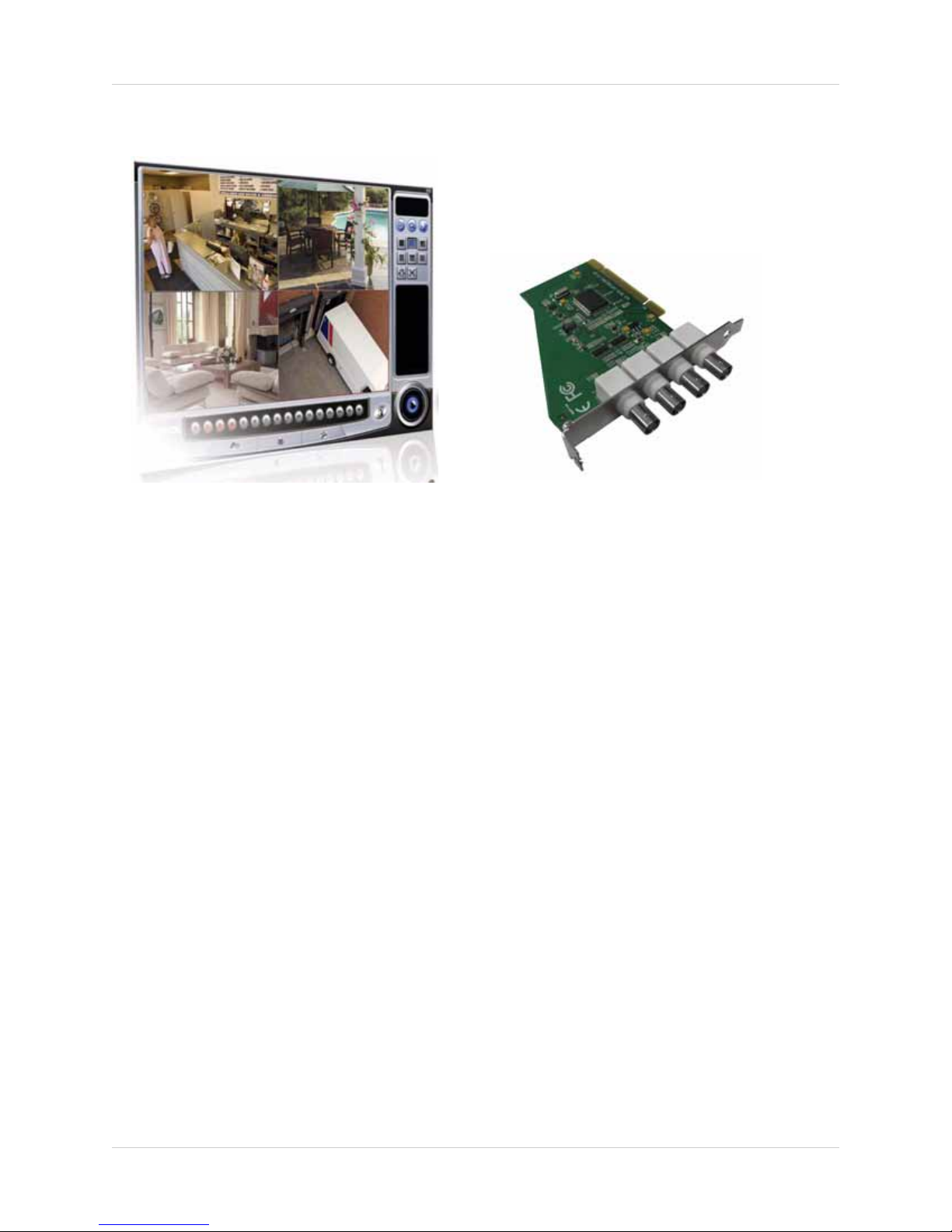
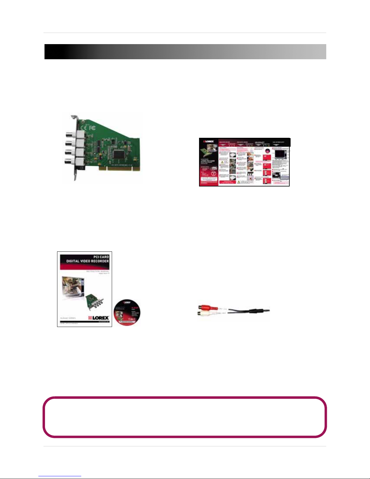
QUICK START GUIDE
QLR460 SERIES
PCI SURVEILLANCE CARD
MANUAL AND SOFTWARE CD
2-CHANNEL AUDIO CABLE
The system comes with the following components:
CAMERA CONFIGURATIONS AND CONTENTS MAY VARY BY MODEL. PLEASE REFER TO YOUR
PACKAGE FOR SPECIFIC CONTENT DETAILS.
CHECK YOUR PACKAGE TO CONFIRM THAT YOU HAVE RECEIVED THE COMPLETE SYSTEM,
INCLUDING ALL COMPONENTS SHOWN ABOVE.
1
INSTALLING THE QLR460 SERIES PCI CARD
Before You Start
• Ground yourself properly before performing hardware
upgrades. Improper grounding damages electronic
components in your system
• It is recommended to work over a non-carpeted area to
prevent static electricity build-up
• Work on a level surface
Prerequisites & Hardware Requirements
Ensure that your system meets the following requirements before you begin installation.
Prerequisites
The system must have:
• A free PCI slot
• A standard PCI opening at the back of the system. Micro form factor cases may not be able to
accomdate the QLR460 series
Minimum System Requirements
• Intel Pentium 4 or higher processor
• Windows XP, Vista, 7 (32-bit versions)
• Optical Drive
• 250GB SATA hard drive
• Separate video card with 64MB of memory
• 800 x 600 VGA color display or better
• Broadband connection required for remote management
2
Installing The QLR460 Series Surveillance Card
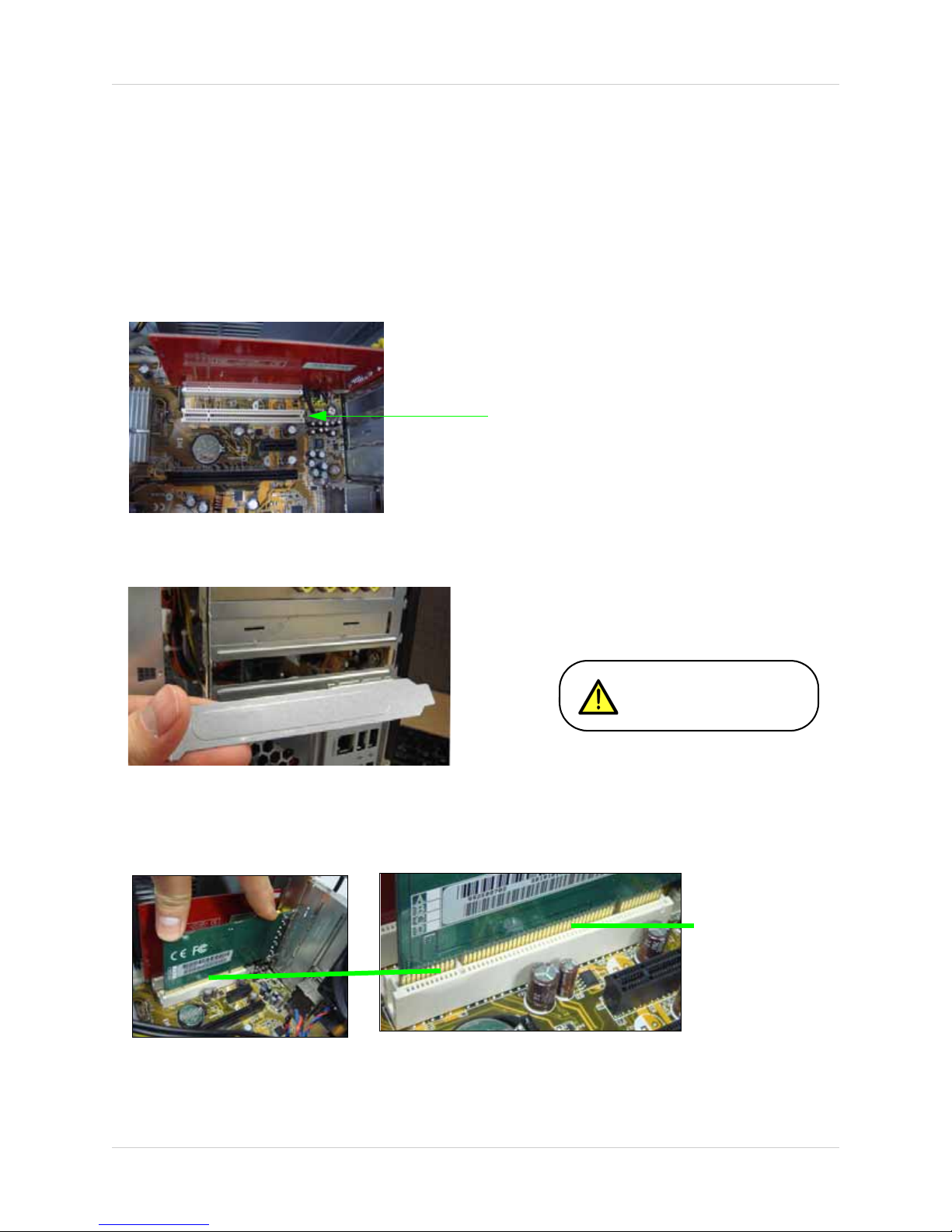
Empty PCI slot
Figure 1.0 Empty PCI slot.
Be careful of sharp edges while
removing the metal plate.
Figure 1.1 Remove PCI slot bracket.
Gold-colored Connector
pins
Figure 1.2 Push the card firmly into the PCI slot until it clicks in place.
1. Shut down the computer. Unplug the power cord from the computer’s power supply.
2. Remove the computer case cover screws. Remove the case cover to access the
motherboard’s PCI slot.
NOTE: Refer to your computer’s owner’s manual for instructions on how to remove the case
cover.
3. Remove the PCI slot’s metal plate at the back of the computer.
4. Push the card firmly into the PCI slot until it clicks in place. The gold-colored connector pins
should not be visible after the card is secure.
3
Installing The QLR460 Series PCI Card
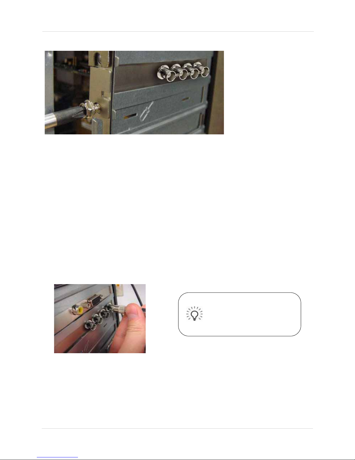
Figure 1.3 Secure PCI card in chassis.
Figure 1.4 Insert BNC connectors into the
video in ports of the surveillance card.
Tip!
Make sure your cameras are
fully functional before
mounting them in the final
location.
5. Secure the PCI card onto the case.
6. Replace the chassis cover on your system.
OPTIONAL: You may connect the 2-Channel audio cable into your sound card if you have an
audio-enabled camera (not included).
NOTE: Audio recording requires audio capable cameras (not included).
Installing the Cameras
To install the cameras to your QLR card:
1. Power off your system.
2. Screw in the BNC connector from the camera to the back of the QLR card. The connection
should be snug and secure.
4
INSTALLING THE SOFTWARE
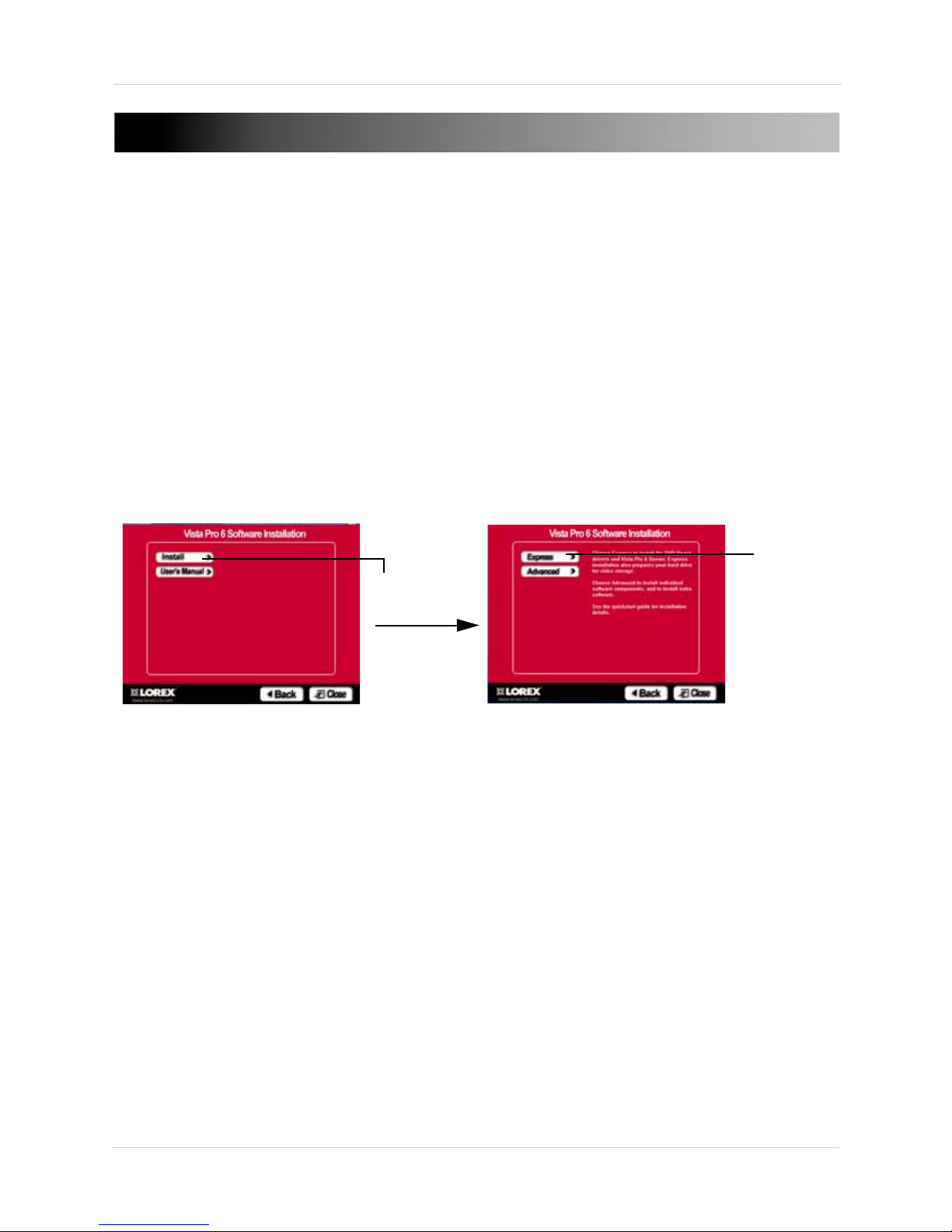
Figure 2.0 Vista Pro 6 Server (Local Viewing) installation window.
Click Install
Click Express
The QLR460 includes local monitoring software, and remote monitoring software. The local
monitoring software is called Vista Pro 6 Server. The remote monitoring software is called Vista
Pro 6 Client. Use Vista Pro 6 Client to monitor your system from another computer.
INSTALLING VISTA PRO 6 SERVER (LOCAL VIEWING)
To install Vista Pro 6 Client:
1. Insert the installation disc into your computer’s CD/DVD reader.
2. Click on the Vista Pro 6 Software button when the software autorun window opens.
• If your system does not support auto-run, you can browse the CD, and search for the Vista Pro
6 Client in the X:\package\DVRMain\ directory, where "X" is your CD/DVD drive. Double click
Setup.exe to install Vista Pro 6 Client.
3. The installation screen opens. Click Install then click Express to install Vista Pro 6 Server.
4. After the installation is complete, remove CD and restart your system.
NOTE: You may receive installation warnings during setup. This is normal. Allow the software
to continue installation when the warning window appears.
INSTALLING VISTA PRO 6 CLIENT (REMOTE VIEWING)
If you want to view your local system from a remote computer, install Vista Pro 6 Client. Vista Pro
6 Client allows you to back up and search your video remotely. You do not need to install Vista Pro
6 Client on a local machine.
To install Vista Pro 6 Client:
1. Insert the installation disc into your computer’s CD/DVD reader.
2. Click on the Vista Pro 6 Software button when the software autorun window opens.
5
Installing the Software
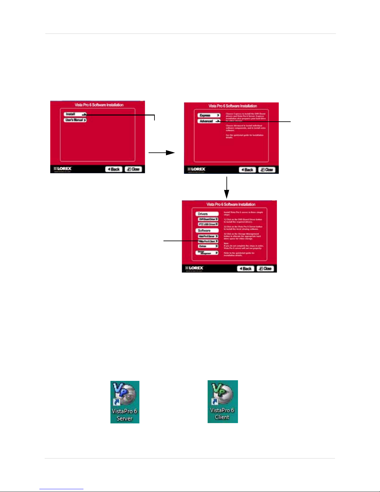
Figure 2.1 Vista Pro 6 Client installation window.
Click Install
Click Advanced
Click on Vista Pro 6 Client
Vista Pro 6 Server (Local Viewing)
Vista Pro 6 Client (Remote Viewing)
• If your system does not support auto-run, you can browse the CD, and search for the Vista Pro
6 Server in the X:\package\Remote Client\ directory, where "X" is your CD/DVD drive. Double
click Setup.exe to install Vista Pro 6 Client.
3. The installation screen opens. Click Install then click Advanced.
4. Click on Vista Pro 6 Client to begin installation.
5. After the installation is complete, remove CD and restart your system.
NOTE: To install Vista Pro 6 Client in the Advanced menu, you must install the following programs
in this order : 1) DVR Board Driver 2) Vista Pro 6 Client 3) Storage Management
NOTE: You may receive installation warnings during setup. This is normal. Allow the software
to continue installation when the warning window appears.
To start the program, double-click the Vista Pro 6 icon on your desktop.
6
Installing the Software
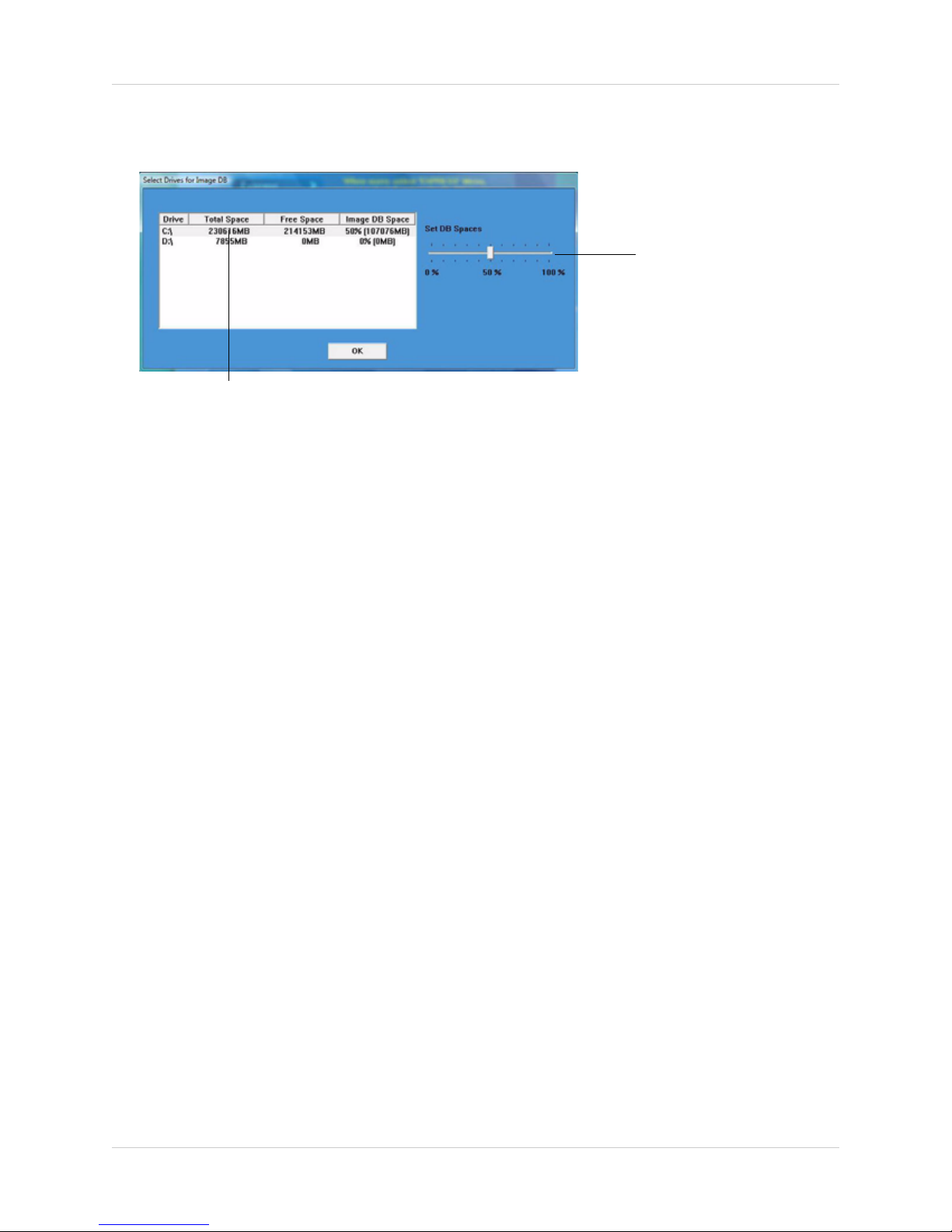
Select hard drive
Drag slider to adjust video
storage space
Figure 2.2 Selecting a save directory and allocating storage space.
SELECTING A SAVE DIRECTORY AND ALLOCATING STORAGE SPACE
During the software installation, a save directory window opens.
To select the save directory:
• Select the hard drive in the hard drive list.
To allocate video storage space:
1. Drag the slider to the right to increase storage space; drag the slider to the left to decrease
storage space.
NOTE: If you allocate a large percentage of your hard drive for video storage, your hard-drive
icon may show up with a red bar (in Windows Vista, 7). This is normal.
2. Click OK to continue. The software begins allocating storage space on your hard drive.
Changing a save directory and re-allocating storage space
You can change the save directory and re-allocate storage space by using the Storage
Management program.
For more information, see:
• Storage Management (See “Appendix E: Re-Allocating Storage Space” on page 72.)
INSTALLING EXTRA SOFTWARE
To install the extra software, you must access the Advanced installation menu. During setup,
instead of selecting Express installation, select Advanced then click Extras.
To install the Image Analyst and Backup Viewer software, click the Extras button in the Advanced
installation window.
For more information, see:
• Image Analyst (See “Appendix C: Using The Image Analyst Software” on page 70.)
• Backup Viewer (See “Appendix D: Using Backup Viewer” on page 71.)
7
Installing the Software
During installation, the software will ask
you to create a directory to store your
videos. Depending on your computer’s
hard drive setup, you will need to select
your save directory accordingly.
HARD DRIVE SETUP SCENARIOS
Your computer may have:
A hard drive with a recovery partition (ie. C drive and D drive with Recovery Software)
If you have a recovery partition, it is recommended to set your C drive as the primary video storage
location. The "recovery" partition is reserved for the operating system, and does not have
adequate space to store your surveillance videos.
A single hard drive (ie. C drive only)
If you only have a single hard drive without a partition, then set your C drive as your storage
directory for the surveillance videos.
A hard drive with a partition (ie. C and D drive)
If you have a second partition in your hard drive (ie. a D drive with ample space (for example,
100GB and above), it is recommended to set your partition as the storage directory for the
surveillance videos. This reduces the chance of losing stored videos if your main hard drive (ie. C
drive) fails.
A hard drive with an external hard drive (ie. C drive + external hd)
If you have an external hard drive, you can set your external hard drive as your storage directory.
It is recommended that you do not remove the external hard drive during recording or playback.
8
Installing the Software
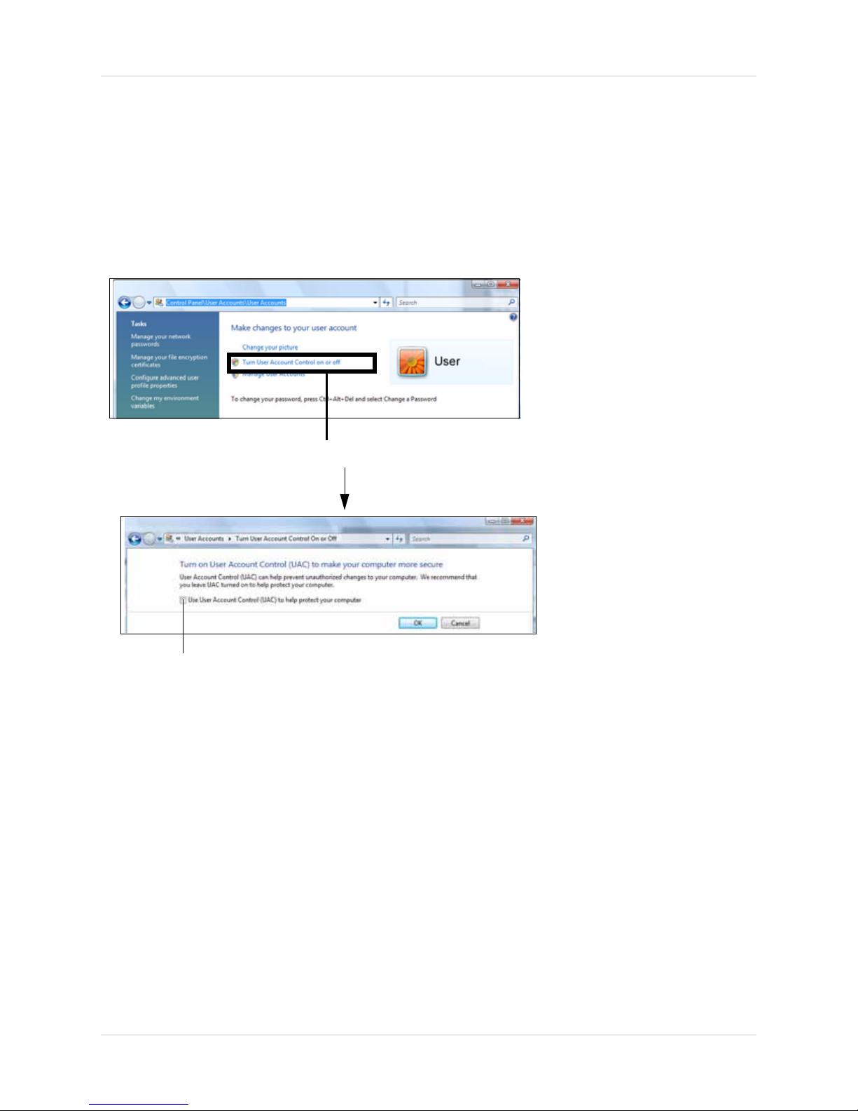
Click on Turn User Account Control on or off
De-select checkbox
Figure 2.3 Disabling User Account Control.
Disabling User Account Control
In order for the Vista Pro 6 software to continually run even after a system restart, you must
disable User Account Control (Windows Vista, 7) . This prevents the login window from appearing
if a system restarts.
To disable User Account Control:
1. Click on the Start Menu>Control Panel>User Accounts>User Accounts.
2. Click Turn User Account Control on or off.
3. De-select the checkbox beside "Use User Account Control to protect your computer" and
then click OK to save your settings. Click on Restart Now to restart your computer.
Disabling Login Password
Disabling the login password allows Vista Pro 6 software to resume automatically in an event that
your system restarts due to power failure or errors.
To disable your user login password:
1. Click on the Start Menu>Control Panel>User Accounts>User Accounts
2. Click Remove Your Password and then enter your current password in the blank field.
3. Click on the Remove Password button.
9
Vista Pro 6 Server: Viewing Mode
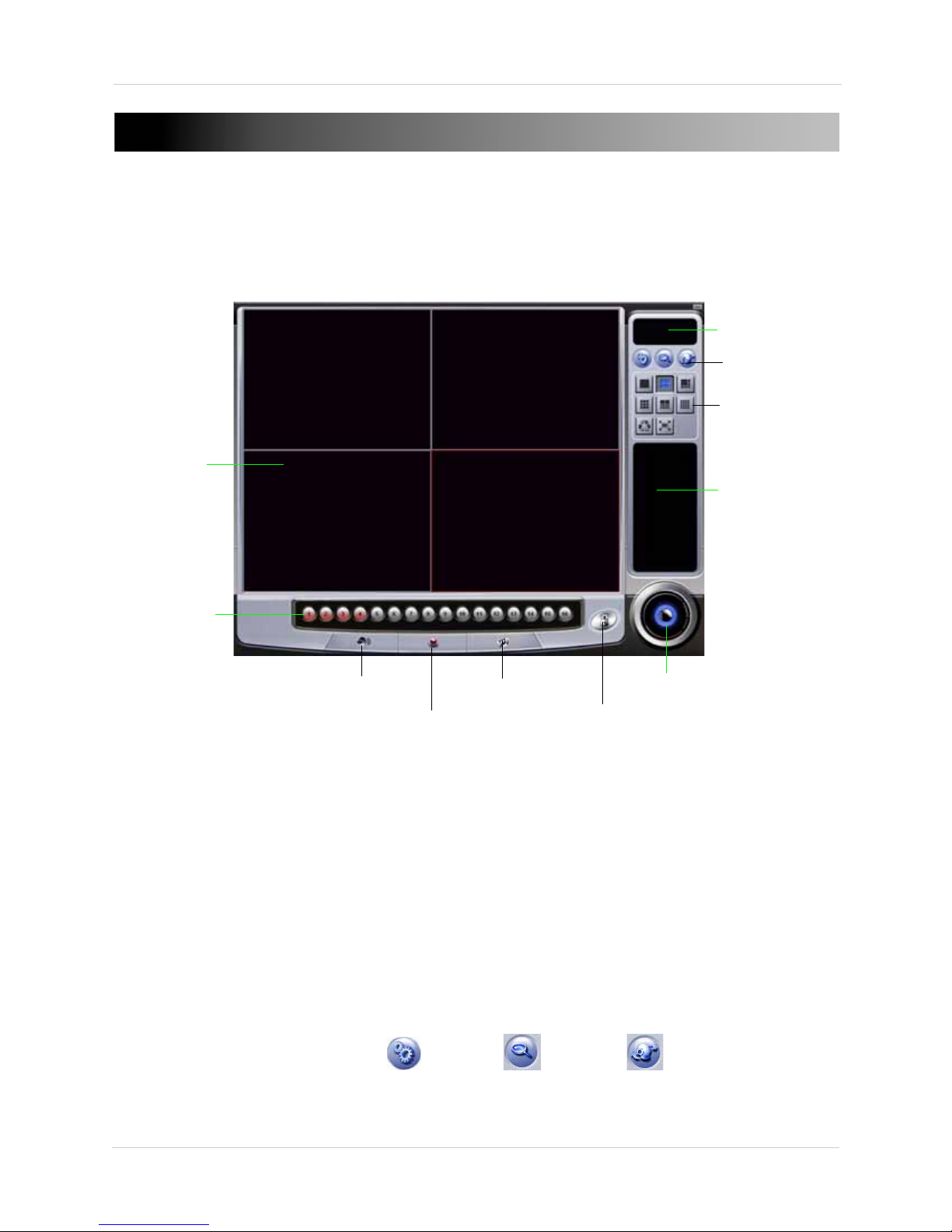
1. Viewing Area
9. View Buttons
7. Exit button
10. Setting buttons
6. Lock Button
2. Camera List
8. Video Log List
3. Live Audio Button
4. Relay Control Button
5. Video Color Adjustment
Figure 3.0 Lorex Viewer in Viewing Mode.
11. Date/Time display
VISTA PRO 6 SERVER: VIEWING MODE
Viewing Mode
Viewing Mode allows you to watch live, streaming events from your cameras. While in Viewing
Mode, you can watch up to 4 cameras simultaneously in split-screen mode.
1. Viewing Area: Displays live video from video cameras connected to the card.
2. Camera List: Displays active cameras. Active camera channels highlight buttons in blue.
Inactive camera channels highlight buttons in red.
3. Live Audio Button: Click to display camera channels with live audio. Channels with active live
audio highlight buttons in red. Channels with inactive audio do not appear in camera list.
4. Relay Control Button: Not supported in this model.
5. Video Color Adjustment: Adjust video brightness, contrast, saturation, and hue.
6. Lock Button: Click to log in to the system to begin viewing or searching video.
7. Exit Button: Click to exit a window or to exit the program.
8. Video Log List: Displays a log of video events.
9. View Mode Buttons: Click to display video in 1-channel, 4-channel, or full screen view.
10. Setting Buttons: Configure Setup( ), Search ( ) and PTZ ( ) settings.
11. Date/Time display: Displays current Date and Time.
10
Vista Pro 6 Server: Viewing Mode
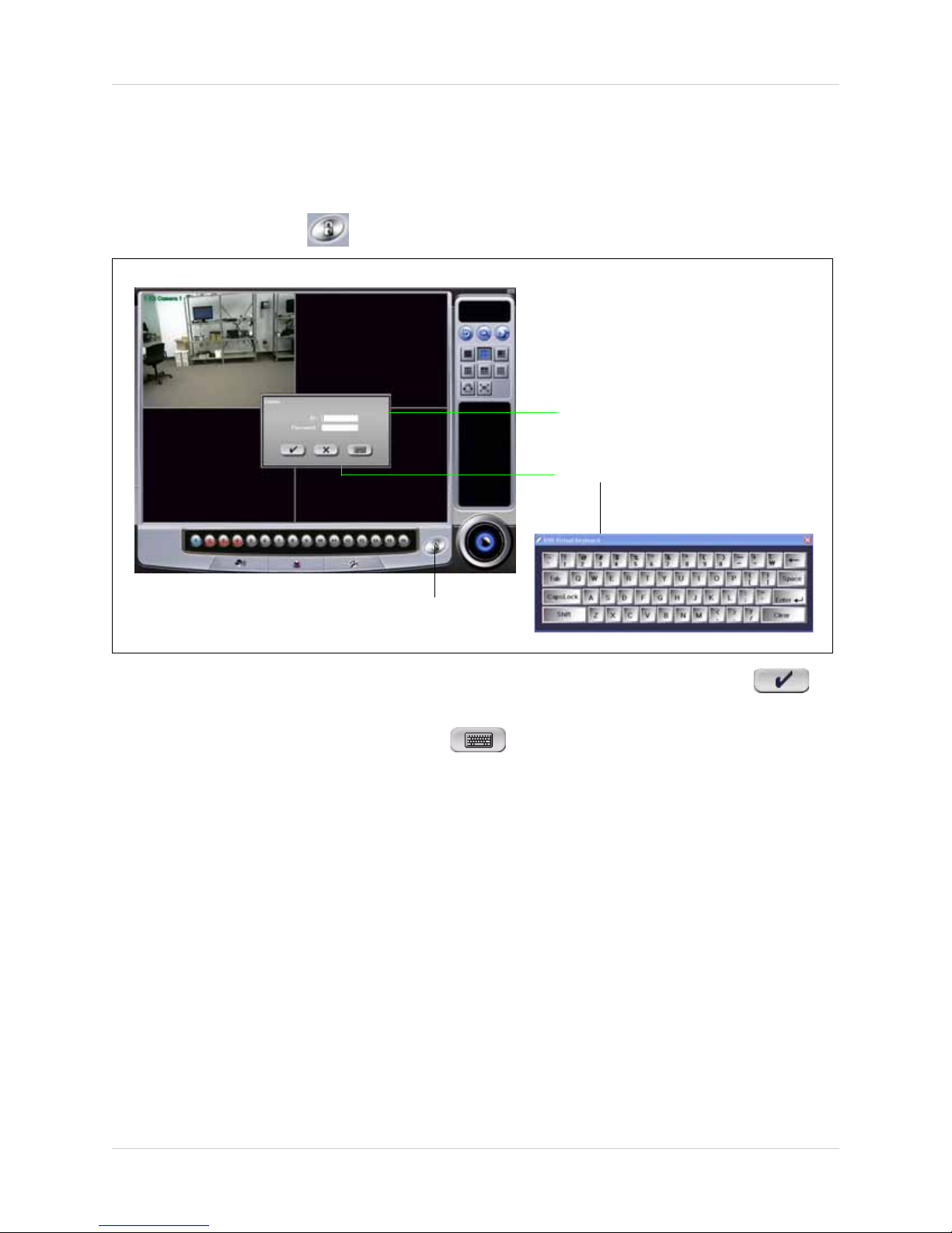
Logon window.
Default ID: admin
Default Password: 1111
Figure 4.0 Log in window and Virtual Keyboard .
Virtual Keyboard button
Lock Button
LOGGING INTO THE VIEWER
To log in to the Viewer:
1. Click the Vista Pro 6 Server shortcut on your desktop, or locate the application in the start
menu.
2. Click the Lock Button ( ). The Logon window appears.
3. Under ID, enter admin; under Password, enter 1111. Click the checkmark button( )to
log in.
NOTE: Click the Virtual Keyboard button ( ) to type in the User ID and Password if you
do not have access to a keyboard.
NOTE: It is recommended to change the default password. For details on changing the admin
password,
NOTE: Click the Exit button on the bottom right hand corner of the window to exit the program.
see “Changing User Account Password” on page 38.
11
Vista Pro 6 Server: Viewing Mode
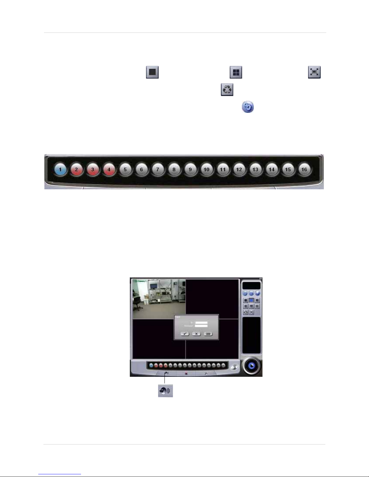
Figure 4.1 Camera List.
Live Audio button
Figure 4.2 Listening for Live Audio.
ADJUSTING VIEWING MODES
To change how the live video feed displays in the window:
• Click the 1-channel view button (), 4-channel view button () or Full Screen button ().
• While in 1-Channel view, press the Auto Sequence button ( ) to cycle through channels 1~4.
• To change the Auto Sequence dwell time, click the
Setup button ( ). Under Auto Sequence
Dwell Time, enter desired dwell time in seconds (1~20 seconds)
Understanding The Camera List
The Camera List allows you to have a "bird’s eye view" of the current status of the channels.
• A Blue button indicates the channel is active.
• A Red button indicates the channel is offline.
• A Gray button indicates the channel is not in use.
Understanding The Audio List
To listen to audio during live viewing, click the Live Audio Button. Then click on the channel with
the audio input. This allows you to listen to audio that the camera receives.
For details on how to set up audio on audio-enabled cameras (not included), see “Audio Tab” on
page 33.
12
Vista Pro 6 Server: Viewing Mode
Color Adjust Button
Figure 4.3 Adjusting video colors.
Brightness
Contrast Saturation
Hue
Apply To All Cameras
Default Values
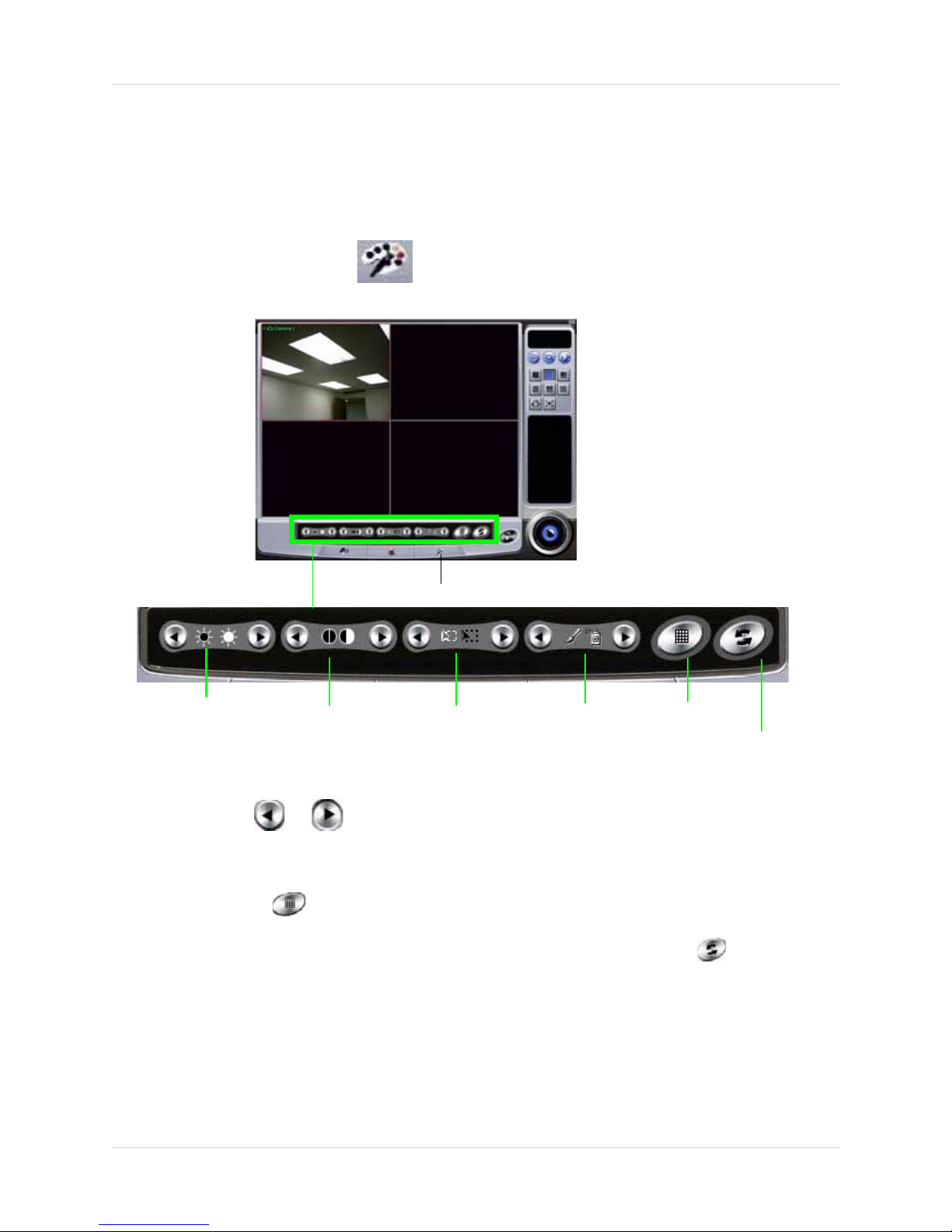
ADJUSTING VIDEO COLOR
You can adjust the brightness, contrast, saturation and hue of the video images.
To adjust the video color:
1. Click the desired channel you wish to adjust color. A red box around the channel indicates the
channel is selected.
2. Click the Color Adjust button ( ) . The Color Adjust settings open near the bottom of the
window.
3. Click the channel that you wish to adjust colors. A red outline around the channel indicates
the channel is selected.
4. Click and hold or to increase or decrease Brightness, Contrast, Saturation, or Hue
settings.
• To apply settings to all channels, adjust the desired video settings, then click the Apply To All
Cameras
button ( )
• To reset color settings to the default value, click the Default Value button ( )
13
Vista Pro 6 Server: Viewing Mode
Setup button
Figure 5.0 Accessing the Setup tab.
Figure 5.1 Enabling Watch Dog
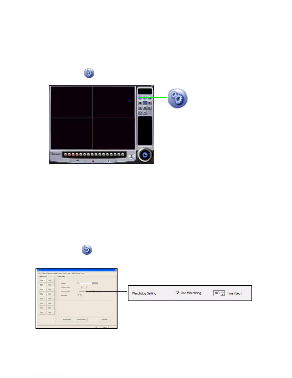
System Tab
The System tab allows you to configuire backup settings, auto-reboot settings, and editing your
system information.
To access the System Tab:
• Click the Setup ( ) button in Live View mode.
ENABLING WATCH DOG
Watch Dog is a feature that continuously monitors potential system errors while the viewer runs.
When a system error occurs, the Watch Dog forces the system to restart. Once the system
restarts, the viewer automatically begins recording.
Forcing a system to restart when there are potential problems ensures the viewer’s stability. This
increases the likelyhood your computer continues to record even if it encounters a system error.
To enable Watch Dog:
1. Click the Setup ( )button. The System tab opens.
2. Beside Watchdog Setting, select the checkbox beside Use Watchdog.
14
 Loading...