

Lorex LW2002 Series Instruction Manual
PORTABLE COLOR LCD
DIGITAL WIRELESS
MONITORING SYSTEM
INSTRUCTION MANUAL
MODELS:
LW2002 Series
Copyright © 2009 Lorex Technology Inc.
English Version 3.0
www.lorexcctv.com
Color may not be exactly as shown. Color varies by model number.
Thank you for purchasing the LW2002
Lorex is committed to providing our customers with a high quality, reliable security product.
To learn more about this system and our complete range of accessory products, along with
Manuals, Quick Start Guides, and Firmware, please visit our website at:
Portable Digital Wireless Monitoring / Surveillance System
www.lorexcctv.com
This product broadcasts over public airways. Digital Wireless is a secure signal; however, video and
audio signals may be intercepted without your consent.
Wireless Disclaimer:
CAUTION
.
RISK OF ELECTRIC SHOCK
DO NOT OPEN
CAUTION: TO REDUCE THE RICK OF ELECTRIC SHOCK
REFER SERVICING TO QUALIFIED SERVICE PERSONNEL.
WARNING: TO PREVENT FIRE OR SHOCK HAZARD, DO NOT
EXPOSE THIS UNIT TO RAIN OR MOISTURE.
CAUTION: TO PREVENT ELECTRIC SHOCK, MATCH WIDE BLADE
OF THE PLUG TO THE WIDE SLOT AND FULLY INSERT.
DO NOT REMOVE COVER (OR BACK).
NO USER SERVICABLE PARTS INSIDE.
The lightning flash with arrowhead symbol, within an
equilateral triangle, is intended to alert the user to the
presence of uninsulated “dangerous voltage” within the
products ‘ enclosure that may be of sufficient magnitude
to constitute a risk of electric shock
The exclamation point within an equilateral triangle is
intended to alert the user to the presence of important
operating and maintenance (servicing) instructions in the
literature accompanying the appliance.
2
p
Important Safeguards
Important Safeguards
In addition to the careful attention devoted to quality standards in the manufacture process of your video
product, safety is a major factor in the design of every instrument. However, safety is your responsibility
too. This sheet lists important information that will help to assure your enjoyment and proper use of the
video product and accessory equipment. Please read them carefully before operating and using your
video product.
Installation
1. Read and Follow Instructions - All the
safety and operating instructions should be
read before the video product is operated.
Follow all operating instructions.
2. Retain Instructions - The safety and
operating instructions should be retained for
future reference.
3. Heed Warnings - Comply with all warnings
on the video product and in the operating
instructions.
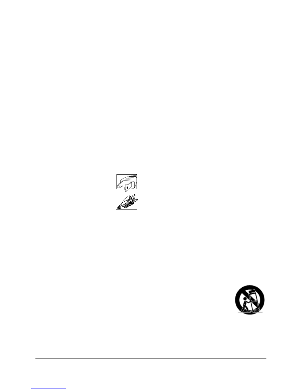
4. Polarization - Do not defeat the safety
purpose of the polarized or grounding-type
plug.
o A polarized plug has two blades with
one wider than the other.
o A grounding type plug has two
blades and a third grounding prong.
o The wide blade or the third prong is
provided for your safety.
o If the provided plug does not fit into
your outlet, consult an electrician for
lacement of the obsolete outlet
re
5. Power Sources - This video product should
be operated only from the type of power
source indicated on the marking label. If you
are not sure of the type of power supply to
your location, consult your video dealer or
local power company. For video products
intended to operate from battery power, or
other sources, refer to the operating
instructions.
6. Overloading - Do not overload wall outlets of
extension cords as this can result in the risk
of fire or electric shock. Overloaded AC
outlets, extension cords, frayed power cords,
damaged or cracked wire insulation, and
broken plugs are dangerous. They may result
in a shock or fire hazard. Periodically examine
the cord, and if its appearance indicates
damage or deteriorated insulation, have it
replaced by your service technician.
7. Power-Cord Protection - Power supply
cords should be routed so that they are not
likely to be walked on or pinched by items
placed upon or against them, paying
particular attention to cords at plugs,
convenience receptacles, and the point where
they exit from the video product.
8. Ventilation - Slots and openings in the case
are provided for ventilation to ensure reliable
operation of the video product and to protect
it from overheating. These openings must not
be blocked or covered. The openings should
never be blocked by placing the video
equipment on a bed, sofa, rug, or other
similar surface. This video product should
never be placed near or over a radiator or
heat register. This video product should not
be placed in a built-in installation such as a
bookcase or rack unless proper ventilation is
provided or the video product manufacturer’s
instructions have been followed.
9. Camera Extension Cables – Check the
rating of your extension cable(s) to verify
compliance with your local authority
regulations prior to installation.
10. Water and Moisture - Do not use this video
product near water. For example, near a bath
tub, wash bowl, kitchen sink or laundry tub, in
a wet basement, near a swimming pool and
the like.
Caution: Maintain electrical safety. Power line
operated equipment or accessories
connected to this unit should bear the UL
listing mark of CSA certification mark on the
accessory itself and should not be modified
so as to defeat the safety features. This will
help avoid any potential hazard from electrical
shock or fire. If in doubt, contact qualified
service personnel.
11. Accessories - Do not place this video
equipment on an unstable cart, stand, tripod,
or table.
Use this video product only with
a cart, stand, tripod, bracket, or
table recommended by the
manufacturer or sold with the
video product. Any mounting of
the product should follow the
manufacturer’s instructions and
use a mounting accessory
recommended by the
manufacturer.
12. Attachments - Do not use attachments
unless recommended by the video product
manufacturer as they may cause a hazard.
3

Important Safeguards
Service
13. Servicing - Do not attempt to service this
video equipment yourself as opening or
removing covers may expose you to
dangerous voltage or other hazards. Refer
all servicing to qualified service personnel.
14. Conditions Requiring Service - Unplug
this video product from the wall outlet and
refer servicing to qualified service
personnel under the following conditions.
a. When the power supply cord or plug is
damaged.
b. If liquid has been spilled or objects
have fallen into the video product.
c. If the video product has been exposed
to rain or water.
d. If the video product does not operate
normally by following the operating
instructions. Adjust only those controls
that are covered by the operating
instructions. Improper adjustment of
other controls may result in damage
and will often require extensive work
by a qualified technician to restore the
video product to its normal operation.
e. If the video product has been dropped
or the cabinet has been damaged.
f. When the video product exhibits a
distinct change in performance. This
indicates a need for service.
15. Replacement Parts - When replacement
parts are required, have the service
technician verify that the replacements
used have the same safety characteristics
as the original parts. Use of replacements
specified by the video product manufacturer
can prevent fire, electric shock or other
hazards.
16. Safety Check - Upon completion of any
service or repairs to this video product, ask
the service technician to perform safety
checks recommended by the manufacturer
to determine that the video product is in
safe operating condition.
17. Wall or Ceiling Mounting - The cameras
provided with this system should be
mounted to a wall or ceiling only as
instructed in this guide, using the provided
mounting brackets.
18. Heat - The product should be situated
away from heat sources such as radiators,
heat registers, stoves, or other products
(including amplifiers) that produce heat.
Use
19. Cleaning - Unplug the video product from the
wall outlet before cleaning. Do not use liquid
cleaners or aerosol cleaners. Use a damp
cloth for cleaning.
20. Product and Cart Combination - Video and
cart combination should be moved with care.
Quick stops, excessive force, and uneven
surfaces may cause the video product and
car combination to overturn
21. Object and Liquid Entry - Never push
objects for any kind into this video product
through openings as they may touch
dangerous voltage points or “short-out” parts
that could result in a fire or electric shock.
Never spill liquid of any kind on the video
product
22. Lightning - For added protection for this
video product during a lightning storm, or
when it is left unattended and unused for long
periods of time, unplug it from the wall outlet
and disconnect the antenna or cable system.
This will prevent damage to the video product
due to lightning and power line surges. The
manufacturer’s instructions and use a
mounting accessory recommended by the
manufacturer.
4

m
General Precautions
General Precautions
1. All warnings and instructions of this manual should be followed
2. Remove the plug from the outlet before cleaning. Do not use liquid aerosol detergents. Use a water
dampened cloth for cleaning
3. Do not use this unit in humid or wet places
4. Keep enough space around the unit for ventilation. Slots and openings should not be blocked
FCC CLASS B NOTICE
Note:
This equipment has been tested and found to comply with the limits for a Class B digital device,
pursuant to Part 15 of the FCC Rules. These limits are designed to provide reasonable protection
against harmful interference in a residential installation. This equipment generates, uses, and can
radiate radio frequency energy and, if not in-stalled and used in accordance with the instruction, may
cause harmful interference to radio communications.
However, there is no guarantee that interference will not occur in a particular installation. If this
equipment does cause harmful interference to radio or television reception (which can be determined
by turning the equipment on and off), the user is encouraged to try to correct the interference by one
or more of the following measures:
o Reorient or relocate the receiving antenna
o Increase the separation between the equipment and receiver
o Connect the equipment into an outlet on a circuit different from that to which the receiver
is connected
o Consult the dealer or an experienced radio or television technician for assistance
This equipment has been certified and found to comply with the limits regulated by FCC, EMC, and
LVD. Therefore, it is designated to provide reasonable protection against interference and will not
cause interference with other appliance usage.
However, it is imperative that the user follows this manual' guidelines to avoid improper usage which
may result in damage to the unit, electrical shock and fire hazard injury
In order to improve the feature functions and quality of this product, the specifications are subject to
change without notice from time to time.
www.lorexcctv.co
5

Features
Features
Digital Wireless Technology provides excellent image quality and clarity
Interference Free, secure and private signal
Up to 450 ft. Wireless Transmission Range*
Listen-In Audio with exceptional sound clarity
Safety Warning Feature Notifies You When out of Range
Auto-Mute: If you notice the speaker turning on and off, this is the innovative Auto-Mute function.
If no sound is detected by the camera, the speaker will automatically shut off to prevent the
constant hiss of ambient noise (common in any environment); the speaker will automatically turn
on when any sound is detected. This serves as an added security feature that can alert you of
any occurrence detected by the camera.
System expandable up to 4 cameras**
Receiver Features:
• 2.4” Color LCD Monitor/Receiver with Superior Image Quality
• Video/Audio Output for viewing on TV/Monitor or recording on VCR/DVD Recorder
• Rechargeable Lithium-Polymer Battery for true portability
• Convenient Receiver Cradle and belt clip included
• Audio Level indicator and Alarm
Camera Features:
• VGA Resolution camera
• Night Vision allows for low light viewing up to 15 ft. / 4.5 meters***
• Built-in Microphone
• Camera can be battery operated for true portable wireless operation
* Maximum open space transmission range. The actual range depends upon building materials and other
obstructions in path of wireless signal.
** Additional cameras sold separately. Visit us on the web at http://www.lorexcctv.com
***IR illumination range of 15ft. / 4.5m under ideal conditions. Objects at or beyond this range may be partially
or completely obscured, depending on the camera application.
for ordering details.
The Digital Wireless signal transmission type used by the Lorex LW2002 series is also
known as FHSS –Frequency Hopping Spread Spectrum. This type of signal is highly
resistant to deliberate jamming as it generates a channel hopping sequence using an
algorithm generated by the receiver system.
6

Table of Contents
Table of Contents
Getting Started .............................................................................................................................................. 8
Wireless Receiver ........................................................................................................................................8
Wireless Receiver .........................................................................................................................................9
Front Controls............................................................................................................................................ 9
Bottom Control......................................................................................................................................... 10
Side Controls ........................................................................................................................................... 10
Charging Cradle Inputs............................................................................................................................10
Wireless Receiver Installation .....................................................................................................................11
Camera........................................................................................................................................................ 11
Front & Back............................................................................................................................................ 11
Side Controls ........................................................................................................................................... 12
Camera Installation ..................................................................................................................................... 12
Connecting Camera Power .....................................................................................................................13
Camera Positioning ................................................................................................................................. 14
Viewing Mode.............................................................................................................................................. 14
Low Signal / No Signal Warnings ............................................................................................................ 15
Adjusting the Receiver Volume ................................................................................................................... 15
Accessing Menu System............................................................................................................................. 16
Main Menu............................................................................................................................................... 16
Pairing Menu ...........................................................................................................................................16
EV Menu.................................................................................................................................................. 16
Power Saving Menu ................................................................................................................................17
Setting Menu ...........................................................................................................................................17
Camera Pairing ...........................................................................................................................................18
Troubleshooting ..........................................................................................................................................19
Appendix A: System Specifications ............................................................................................................20
Appendix B: About Digital Wireless Technology......................................................................................... 21
7
Getting Started
Getting Started
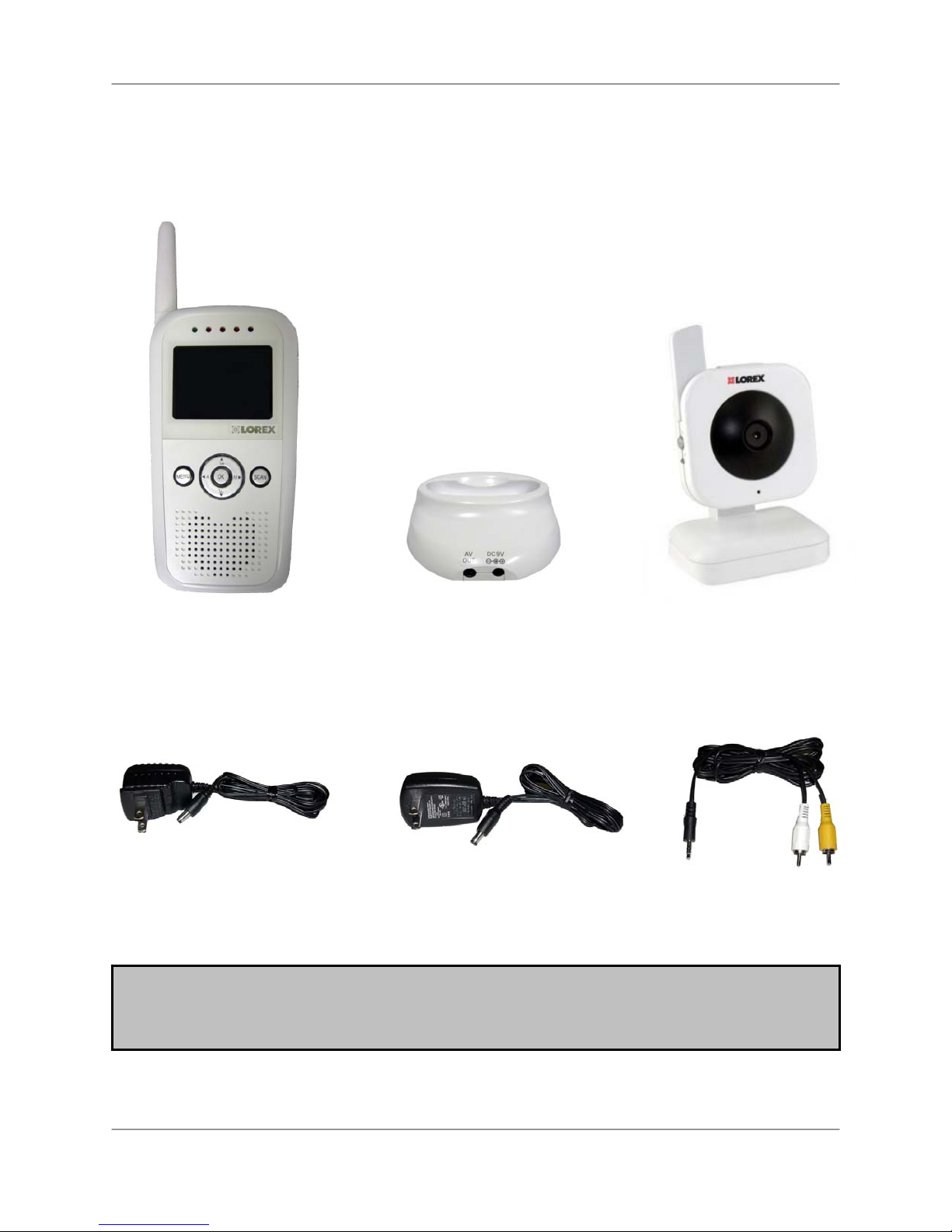
The system comes with the following components:
1 x WIRELESS
RECEIVER
1 x POWER ADAPTER
(FOR RECEIVER)
1 x RECEIVER
CRADLE
1 x POWER ADAPTER(S)
(FOR CAMERA) *
1 x WIRELESS
CAMERA(S)*
1 x RCA VIDEO
CABLE
CHECK YOUR PACKAGE TO CONFIRM THAT YOU HAVE RECEIVED THE COMPLETE
SYSTEM, INCLUDING ALL COMPONENTS SHOWN ABOVE.
* 1 of each of the above is provided with the camera. Please see your Product Package for the
number of cameras included with your system.
8
Wireless Receiver
Wireless Receiver
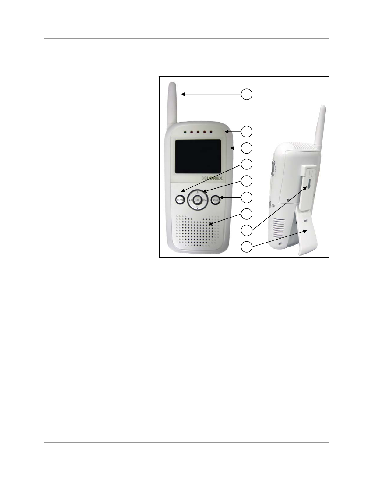
Front Controls
1. Receiver Antenna: Receives and
sends signals to and from the
camera(s)*
1
2. Power / Audio Level LEDs: The
Green LED indicates the receiver
power is ON or OFF. The Red LEDs
indicate the Audio Levels (Low to
High).
2
3. LCD Screen: Displays video from
3
the camera.
4
4. MENU Button: Press to access the
Receiver Menu. Press the button
again to exit.
5
5. Navigation Controls / OK Button:
6
Use the controls in Viewing Mode and
Menu Modes:
7
• Viewing Mode: The following
controls are used while watching
live video from the camera:
8
o Press the UP/DOWN
▲▼arrows to Increase or
9
Decrease the volume.
o Press the LEFT “◄A” arrow
to view cameras* in automatic switching mode.
o Press the RIGHT “M►” arrow to manually switch between cameras*.
• Menu Mode: Use the UP/DOWN/LEFT/RIGHT ▲▼◄► arrows to navigate in Menu Mode. Press the
OK Button to confirm the menu selection.
6. SCAN Button: When the Scan button is pressed, the LCD screen is turned off and the system
continuously scans all available cameras while the monitor is dark. The SCAN feature can be used for the
following two reasons: (1) To prevent the user from being disturbed (i.e. when sleeping) by the bright LCD
screen, or (2) To conserve battery power. If audio is detected above the preset audio trigger level on the
camera(s)*, the Receiver will beep and display the triggered Camera. The camera receiver will return to
Scan mode several seconds after the Alarm has completed. Press the AUTO “◄A” or MANUAL “M►”
button to exit Scanning Mode.
7. Speaker: Produces the sound transmitted from the cameras*.
NOTE: If you notice the speaker turning on and off, this is the innovative Auto-Mute function. If no sound
is detected by the camera, the speaker will automatically shut off to prevent the constant hiss of ambient
noise (common in any environment); the speaker will automatically turn on when any sound is detected.
8. Belt Clip / Wall Mount: Use the belt clip to easily carry the Receiver with you. Use the mount hole to
hang the Receiver on a wall (using a screw – not included).
9. Stand: Flip the stand out to place the receiver on a flat surface (such as a table or countertop).
Alternatively, place the receiver in the Receiver Cradle.
* You must have more
than one camera
configured on the system
when using functions that
require more than one
camera.
9
Wireless Receiver
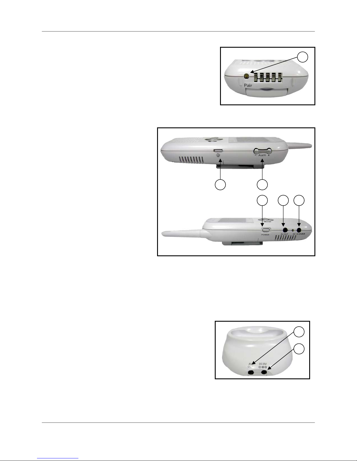
Bottom Control
10. Pair Button: Press the Pair button when pairing the receiver
with a camera.
10
Side Controls
11. Night Light Button: Press to remotely
turn the Night Light ON or OFF (for the
camera currently being displayed on the
LCD screen).
12. Alarm +/- Button: Press to increase
or decrease the sensitivity of the audio
alarm.
13. Power Button: Press to turn the
receiver ON or OFF.
14. A/V Out Port (Optional Use):
Connect the included A/V cable to view
video from the receiver on a TV or Monitor,
or record to a DVD Recorder or VCR.
Alternatively, use the A/V Out port on the
Receiver Cradle.
NOTE: Using this feature will turn off the
LCD screen. The LCD screen will turn
back on when the A/V cable is
disconnected.
15. DC 9V Power Input: Connect the included DC 9V Power Adapter to power the receiver and/or charge
the Receiver battery (when the receiver is not in the cradle).
11 12
13 14 15
Receiver Cradle Inputs
16. A/V Out Port: Connect the included A/V cable to view the
receiver picture (when docked) on a TV or Monitor, or record to
a DVD Recorder or VCR. (NOTE: The power cable needs to
be connected for this feature to work. Only one A/V out port
should be used at a time).
17. DC 9V Power Input: Connect the DC 9V Power Adapter
(included) to the Receiver Cradle to power the receiver and/or
charge the receiver (when docked).
NOTE: When the receiver is docked, and the A/V cable is connected (power cable as needs to be
connected), the LCD screen on the receiver will be blacked out. The LCD screen will turn back on when
the A/V cable is disconnected.
10
16
17
Wireless Receiver Installation
Wireless Receiver Installation
Determine if you will be using the Receiver Cradle, or connecting the cables directly to the receiver before
installation:
1. Place the Receiver Cradle or Receiver in a place that will have clear reception with your
camera(s).
2. Plug the AC adapter power output cable into the 9V POWER input of the cradle or receiver. Plug
the power plug into a wall outlet or surge protector.
3. Leave the receiver to charge for 6 hours prior to first time use so the built-in rechargeable
receiver battery is fully charged. DO NOT remove the power cable from the receiver or from the
cradle during initial charging process. After initial charge, charge as required.
4. If you wish to view the receiver images on a larger screen, connect the included AV cable to the
cradle or receiver, and connect the other end of the cable to the Video IN (Yellow) and Audio IN
(White) ports on the TV, VCR or other viewing/recording device.
NOTE: The purpose of the AV output is for convenience only. When using with large
screen TV/Monitor, the picture might be grainy as the camera limits video resolution to
VGA (640x480 pixels). This is not a product defect. For best performance use with TV/Monitor
PIP (Picture in Picture) function. Check your TV/Monitor product manual to see if this feature is
available on your TV/Monitor. This allows you to view TV or other video source and see video
from the camera in a small window on the same screen.
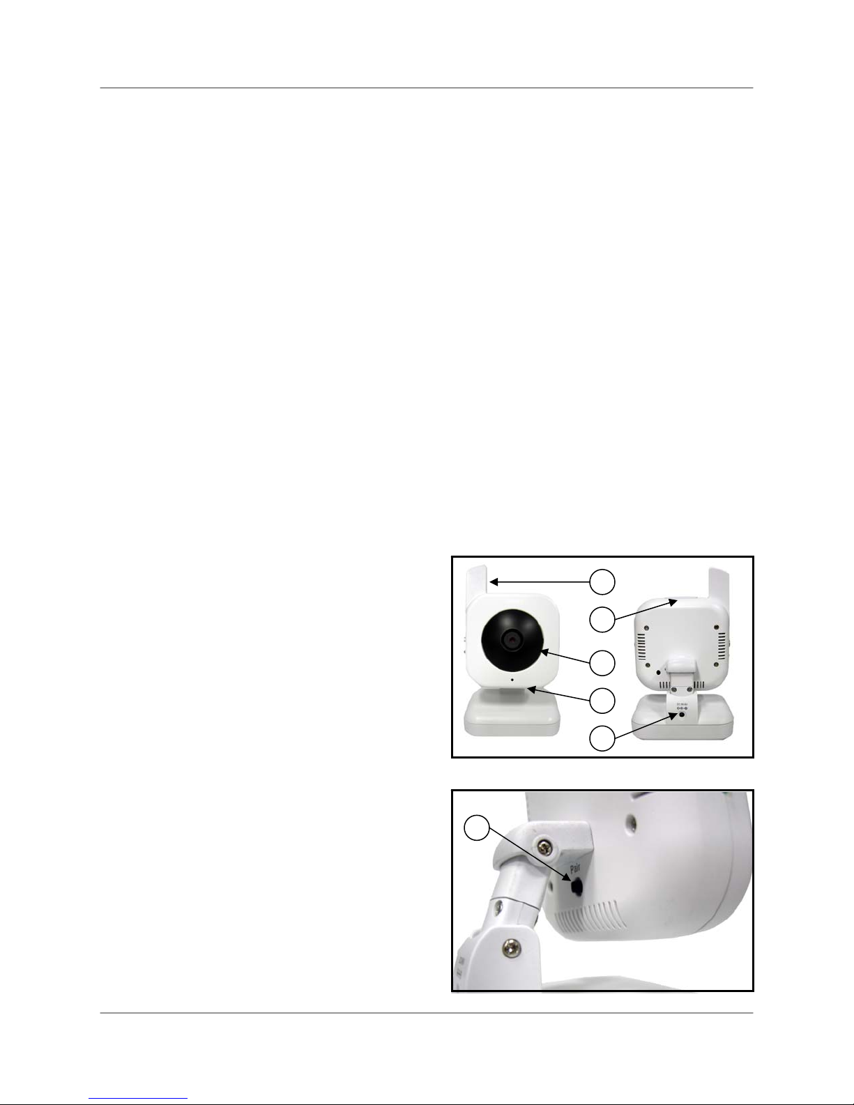
Camera
Front & Back
1. Camera Antenna: Receives and sends signals to
and from the receiver.
2. Night Light Switch: Press to turn the Light ON or
OFF. Alternatively, press the Light button on the
Receiver to remotely turn the Camera Light ON or
OFF.
3. Lens / IR LED Cover: Infrared LEDs provide
viewing in no/low light conditions.
4. Microphone: Receives sounds for the area near
the camera, and transmits sound from the camera to
the receiver.
5. DC 9V Power: Connect the DC 9V Power Adapter
to the camera.
NOTE: The camera can also be powered using 4 AA
batteries (not included) installed in the base. If the
camera is plugged in with the AC Adapter, the
batteries will not be used. The batteries are intended
for short term, portable camera use.
6. PAIR Button: The pairing button is located on the
back of the camera behind the stand mount.
1
2
3
4
5
6
11
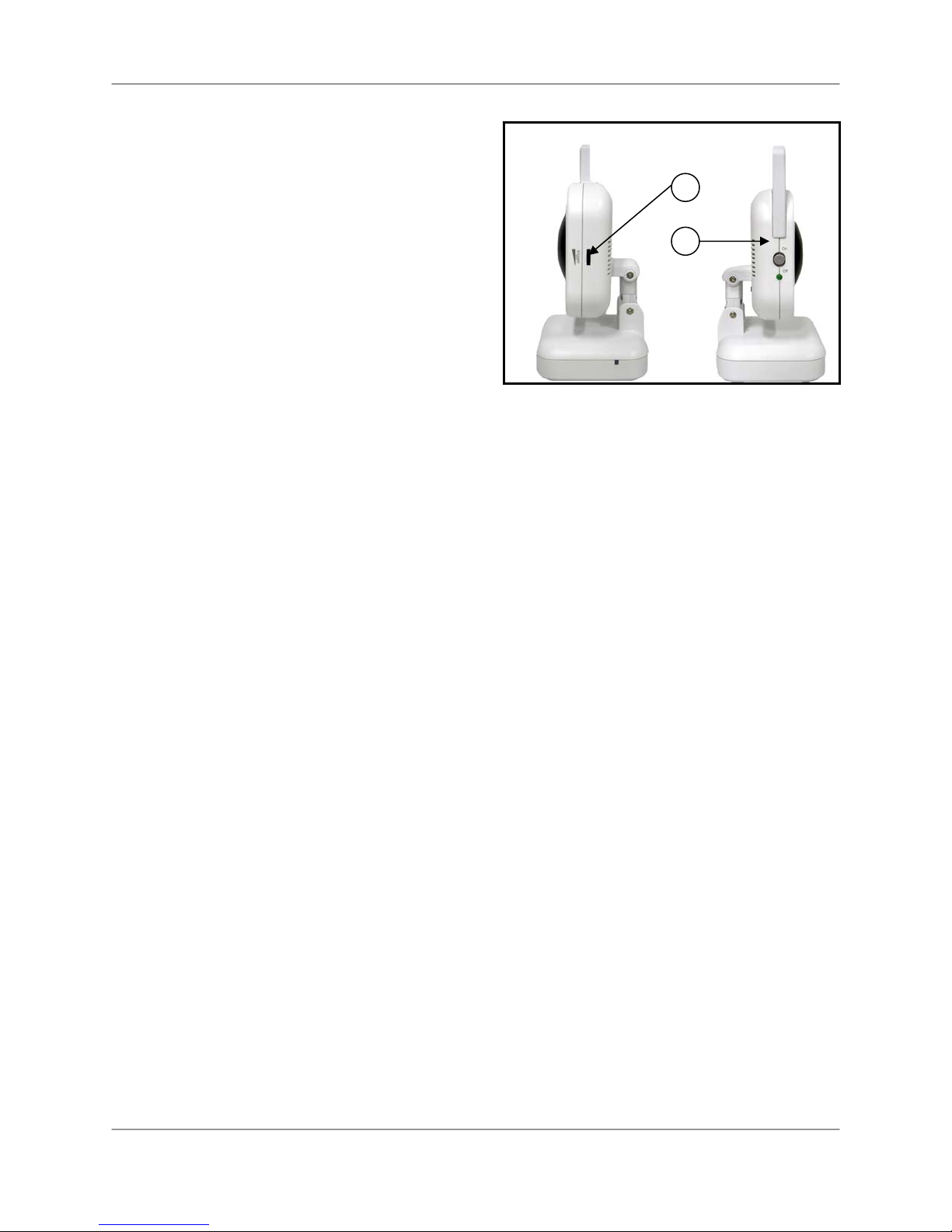
Camera Installation
Side Controls
7. Sound Alarm Sensitivity: The receiver will beep to
alert the user when the sound is above a preset sound
level. Adjust the side wheel to Increase or Decrease the
level of sensitivity.
8. Camera ON/OFF Switch: Turns the camera ON or
OFF.
7
8
Camera Installation
Before you install the camera, carefully plan where and how it will be positioned, and where you will route
the cable that connects the camera to the power adaptor.
• Before starting permanent installation, verify its performance by observing the image on the
receiver when camera is positioned in the same location/position where it will be permanently
installed and the receiver is placed in the location where it will be used most of the time.
Installation Warnings:
• Aim the camera(s) to best optimize the viewing area: Select a location for the camera that
provides a clear view of the area you want to monitor, which is free from dust, and is not in lineof-sight to a strong light source or direct sunlight.
• Avoid installing the cameras where there are thick walls, or obstructions between the cameras
and the receiver.
Night Vision
This camera has built-in IR LEDs, which provides the camera with the ability to view images in no/low
light conditions. It is important to use the provided power adaptor (and not the batteries) when using the
camera for prolonged periods in low light conditions, as the built-in IR LEDs will drain the battery more
quickly than regular daytime use.
12

Camera Installation
Installing the Camera:
1. Carefully unpack the camera.
NOTE: If you are installing cameras that did not come with the system, please see the Camera Pairing
section of this manual for details on installation.
2. Mount the camera to the wall:
• Mark the position of the screw holes on the wall.
• Drill holes and insert 3 screws.
• Firmly attach the camera to the wall by placing the stand
over the installed screws and pushing the base downwards
to secure.
NOTE: The camera can also be placed on a flat surface, such as a
table or shelf, and no mounting hardware is required.
3. Adjust the viewing angle of the camera.
NOTE: You can install additional cameras (maximum of 4
cameras).When adding cameras that were not included in the
original box; you will need to pair up the cameras with the receiver.
Refer to the camera pairing section of this manual.
Position the base holes over the
screws. Slide the base down to
lock the base in place.
Connecting Camera Power
The camera can be powered either by using the included Power Adapter or using batteries (requires 4 x
AA batteries, not included).
NOTE: Wireless cameras require a power source (either an electrical outlet or battery power) to operate.
If you plan to permanently mount the camera in a location, it is recommended to use the included Camera
Power adaptor to prevent interruptions in the image, as using battery power is intended as a temporary
power solution.
POWER ADAPTER:
Connect the Power Adapter to the camera. Make
sure the power adapter is placed into a grounded
outlet or surge bar to protect the camera from power
fluctuations.
Power Adaptor:
Connect the Power
Adapter to the 9V
Input on the back of
the camera.
13
Viewing Mode
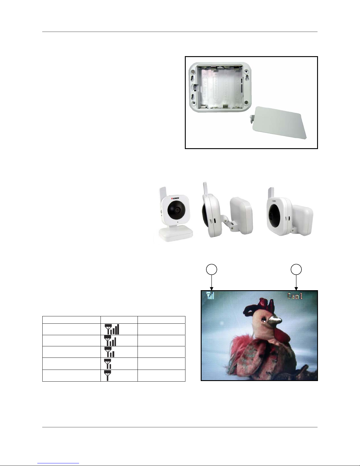
BATTERY PACK:
1. Remove the battery cover off the base of the
camera.
2. Insert 4 x AA batteries (not included) into the
Battery Pack. Make sure to correctly line up the
Positive (+) and Negative (-) terminals of the
batteries.
3. Place the battery cover back on.
NOTE: If the camera is plugged in with the AC
Adapter, the batteries will not be used. The batteries
are intended for short term, portable camera use
only.
Camera Positioning
The camera can be placed on a flat
surface, or wall mounted. The versatile
stand allows for several different
mounting options.
Viewing Mode
1. SIGNAL INDICATOR – The signal indicator shows the
strength of the signal being received from the camera.
The number of bars in the Signal Indicator shows the
strength of the signal – One or No Bars indicates the
signal is poor, and 4 bars indicate a very strong signal.
Signal Indicators:
Signal Strength Indicator Warning
Perfect
Good
Fair
Low
No Signal
2. CHANNEL INDICATOR – Displays the current channel number. Press the Right “M►” Button on the
Receiver to switch between available cameras.
NOTE: To automatically switch between channels, press the Left “◄A” Button (AUTO).
None
None
Low Signal
Low Signal
No Signal
1 2
14
 Loading...