

Page 1

Instruction
Manual
LNZ3522B HD
MICRO PT
DOME
CAMERA
English / Français / Español
Page 2

Instruction Manual
LNZ3522B HD MICRO PT DOME
CAMERA
#; r. 1.0/19290/19290; en-US
Page 3
Thank you for purchasing this product. Lorex is committed to
providing our customers with a high quality, reliable security
solution.
This manual refers to the following models:
LNZ3522B
For the latest online manual, downloads and product updates, and
to learn about our complete line of accessory products, please visit
our website at:
www.lorextechnology.com
WARNING
RISK OF ELECTRIC
SHOCK
DO NOT OPEN
WARNING: TO REDUCE THE RICK OF ELECTRIC
SHOCK DO NOT REMOVE COVER. NO USER
SERVICABLE PARTS INSIDE.
REFER SERVICING TO QUALIFIED SERVICE
PERSONNEL.
#; r. 1.0/19290/19290; en-US
Page 4
The lightning flash with arrowhead symbol,
within an equilateral triangle, is intended to
alert the user to the presence of
uninsulated "dangerous voltage" within the
product’s enclosure that may be of
sufficient magnitude to constitute a risk of
electric shock.
The exclamation point within an equilateral
triangle is intended to alert the user to the
presence of important operating and
maintenance (servicing) instructions in the
literature accompanying the appliance.
WARNING: TO PREVENT FIRE OR SHOCK
HAZARD, DO NOT EXPOSE THIS UNIT TO RAIN OR
MOISTURE.
CAUTION: TO PREVENT ELECTRIC SHOCK,
MATCH WIDE BLADE OF THE PLUG TO THE WIDE
SLOTAND FULLY INSERT.
#; r. 1.0/19290/19290; en-US
Page 5

Table of contents
1 Safety Instructions . . . . ............................... . . . . . . 1
2 LNZ3522B Features .......... ... .. . . . . . . . . . . . . . . . . . . . ...... 2
3 Getting Started ... . .. . . . . . . . . . . . . . . . . ....................... 4
4 Camera Overview . ............................. .. . .. . . . . . . . 5
5 Connecting the Camera . . . . . . . . . . . . . . . .................... 6
5.1 OPTION 1: Connecting Cameras to an
NVR........................ . . . . . . . . . . . . . . . . . . . .. ... 6
5.2 OPTION 2: Connecting Cameras to the
Local Area Network (LAN) . ....................... 7
6 Installation . . . . . . . . . . . . . . . . . . . ............................. .12
6.1 Installation Tips and Warnings .... ... . . . . . . . . . . . .12
6.2 Installation (Indoor/Outdoor) ......... . . . . . . . . . . . .12
7 Controlling the PT Camera with an NVR . ...............17
7.1 Controlling the Camera’s Pan-Tilt
Movement (Local NVR) . . . .......................18
7.2 Advanced Pan-Tilt Controls... .. . . . . . . . . . . . . . . . . .19
8 Technical Specifications .. . . .. .......................... .22
8.1 Dimensions . . . . . . . . . . . . . .. ........................23
9 Troubleshooting . . . .. .......................... . .. . . . . . . . . .24
10 Resetting the Camera........ .. . . . . . . . . . . . . . . . . . . . .. ......26
11 Notices .. . . . . . . . . . . . . . . . ............................... . . . . .28
11.1 FCC/IC Notice . . . . . . . . . . . . . . ......................28
11.2 Modification ....................... .. . . . . . . . . . . . . .28
11.3 ROHS........ . . . . . . . . . . . . . . . . . . . . . . ...............29
#; r. 1.0/19290/19290; en-US vii
Page 6

1 Safety Instructions
• Read this guide carefully and keep it for future reference.
• Follow all instructions for safe use of the product and handle with
care.
• Use the camera within given temperature, humidity, and voltage
levels noted in the Technical Specifications.
• Camera is rated for outdoor use and is weatherproof when properly installed. Camera is not intended for submersion in water. Installation under a sheltered environment is recommended.
• Do not disassemble the camera.
• Do not point the camera directly towards the sun or a source of intense light.
• Make sure to install the camera in a location that can support the
camera weight.
• Make sure there are no live electrical cables in the area where you
plan to mount the camera.
• Periodic cleaning may be required. Use a damp cloth only. Do not
use anything other than water to clean the dome cover, as chemicals such as acetone can permanently damage the plastic.
#; r. 1.0/19290/19290; en-US 1
Page 7

2 LNZ3522B Features
• High definition 1080p resolution 2.1 MP image sensor.
1
• Full 360° pan rotation for complete area coverage and 100° per
second panning speed.
• Micro dome form factor only 5" in diameter and just over 2" tall.
• 25 programmable preset positions.
• Built-in microphone for listen-in audio.
• Wide angle 3.6mm lens with 90° field of view.
• Single network cable setup for video, power and Pan/Tilt control.
• Program preset viewing points when connected to a compatible
NVR.
1
• Remote control of the Pan/Tilt camera using a smartphone or tablet when connected to a compatible NVR.
1
• Digital wide dynamic range backlight compensation ensures clear
images in high and low light areas.
• 3D DNR (Digital Noise Reduction) for clear accurate images.
• ClearNight imaging for superior low light performance.
2
• Weatherproof for outdoor & indoor installation (IP66 Rated).
3
• Extreme temperature performance (–4° ~ 140°F / –20° ~ 60°C).
• Vandal-proof heavy-duty durable metal housing.
• Simple installation with Power over Ethernet (PoE) CAT5e cable.
• CAT5 PoE extension cable included per camera.
• Expand your coverage with Ethernet cable up to 300’ from the
NVR.
#; r. 1.0/19290/19290; en-US 2
Page 8

2 LNZ3522B Features
Note
1. Compatible with Lorex HD NVR LNR100 & LNR400 Series
only.
2. This camera features an ultra-low light sensitive image sensor
and therefore does not feature Infra-Red LEDs. The camera
requires ambient lighting (for example, street/building lighting,
star or moon light) to render a night time image. In total darkness (zero Lux) the camera will not produce a night time image and therefore the camera should not be installed in areas
with complete darkness.
3. Not intended for submersion in water. Installation in a sheltered location recommended.
#; r. 1.0/19290/19290; en-US 3
Page 9
3 Getting Started
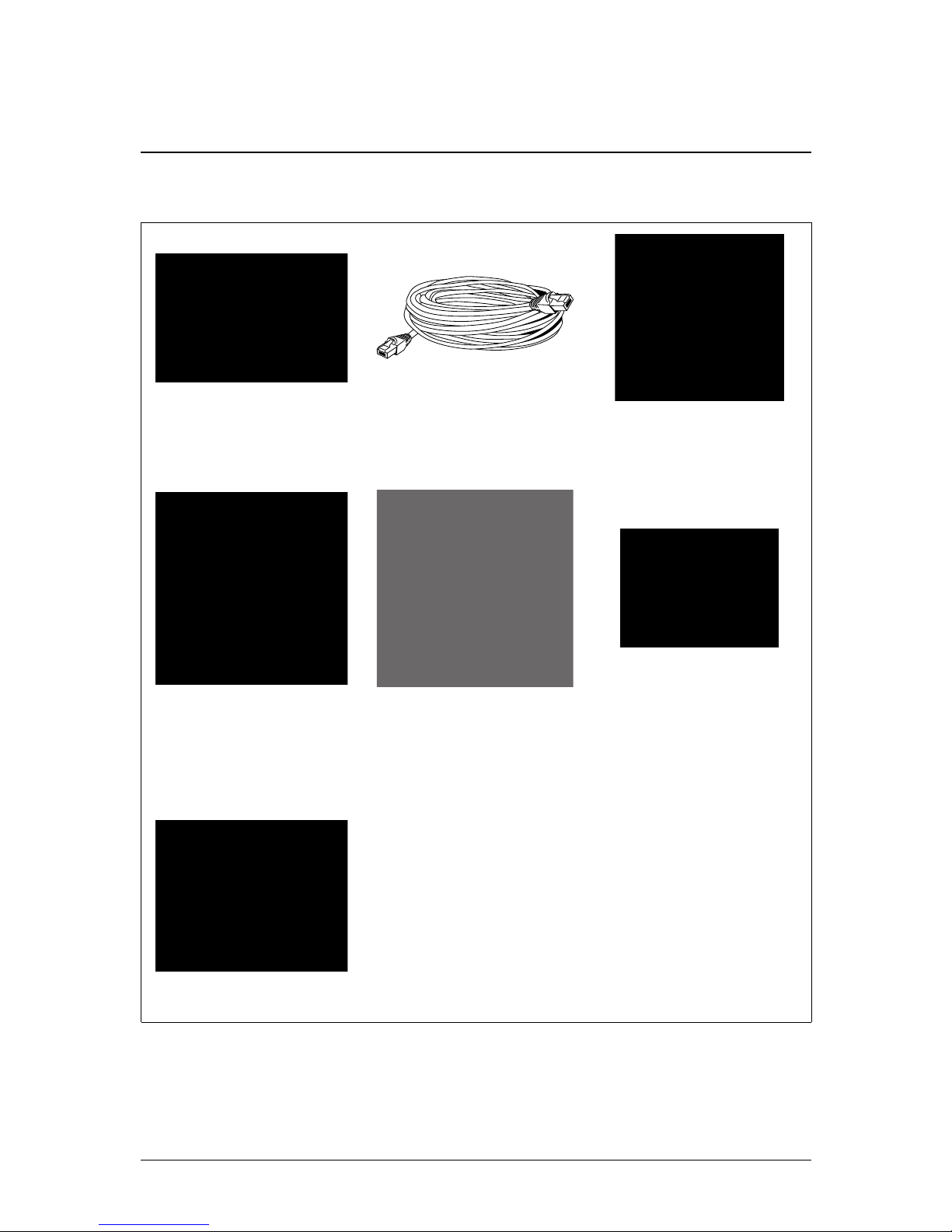
The system comes with the following components:
Micro PT Dome
Camera
Ethernet Extension
Cable
Allen Key
Metal Mounting
Plate
Mounting Template
Mounting Screws &
Anchors
(for mounting plate)
Instruction Manual
#; r. 1.0/19290/19290; en-US 4
Page 10

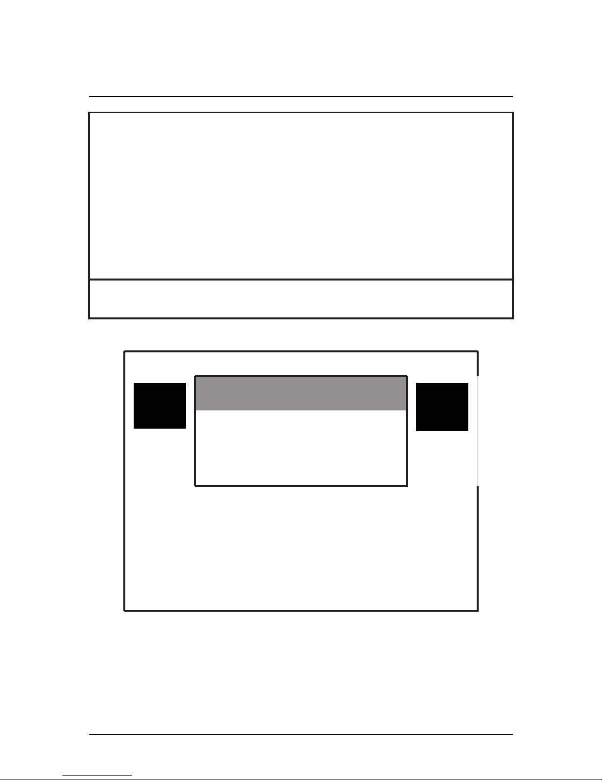
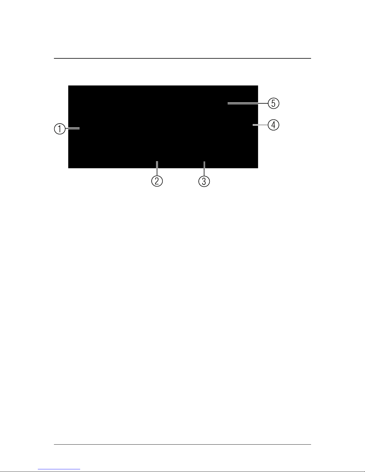
4 Camera Overview
1. Dome Cover
2. Ethernet Port: Connect the camera to an NVR or PoE switch on
your network using the included Ethernet cable.
3. 12V DC Power: If not using PoE, connect the camera to a 12V
DC power source (not included). Power adapters for this camera
are available for purchase on www.lorextechnology.com (model
#: CVA4902).
4. Lens: Camera lens.
5. Microphone: Built-in microphone.
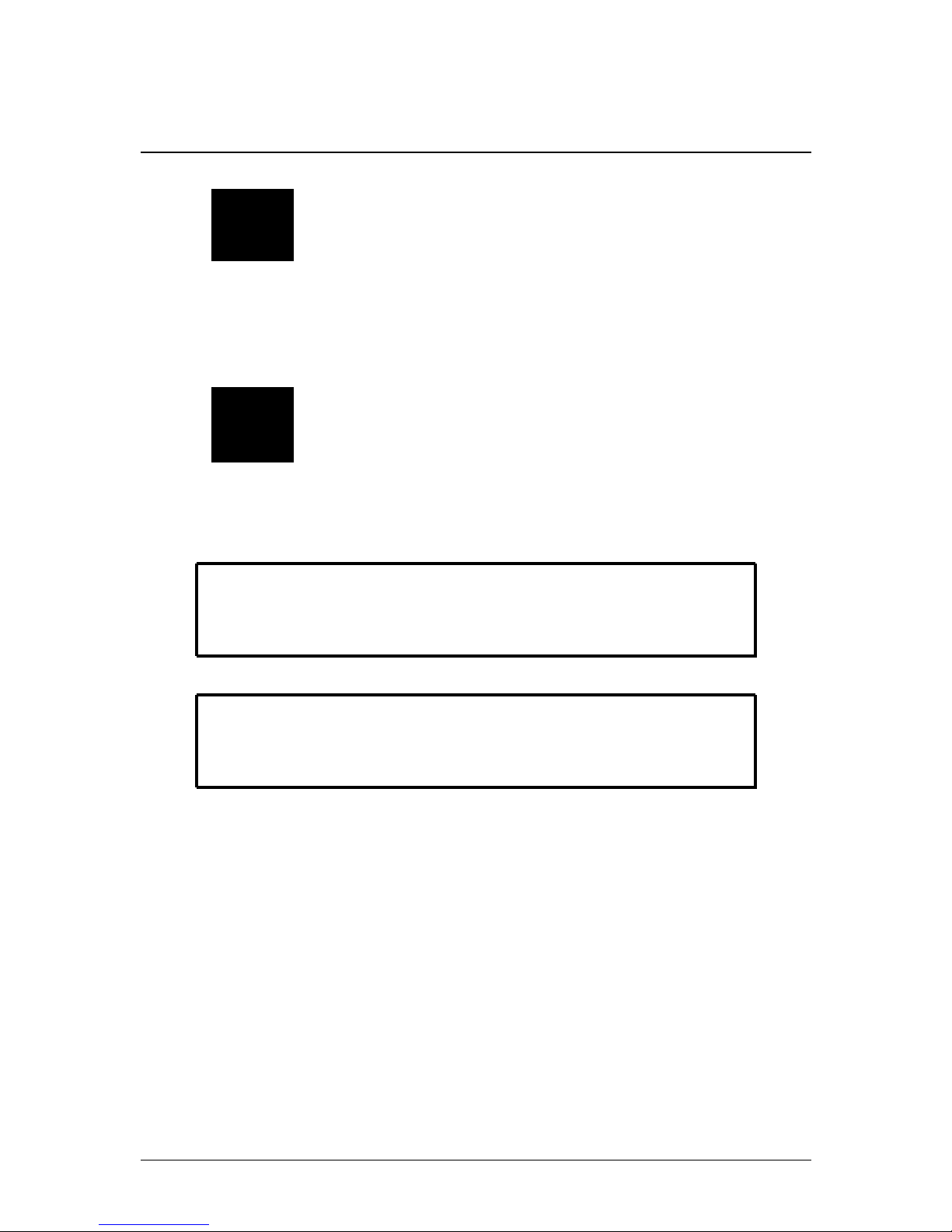
6. GND Port: The pre-inserted screw grounds the camera.
7. Reset Button Compartment: Open using a Phillips screwdriver
to reveal the reset button. Press and hold for 4 seconds to reset
camera settings.
#; r. 1.0/19290/19290; en-US 5
Page 11
5 Connecting the Camera
Note
It is recommended to connect the camera to your NVR and test
the Pan-Tilt controls before permanent installation. For instructions
on how to setup Pan-Tilt controls, see 7 Controlling the PT Cam-
era with an NVR, page 17.
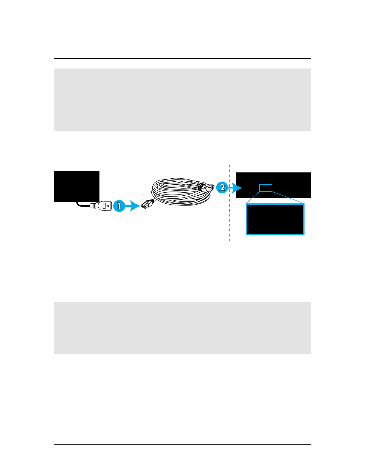
5.1 OPTION 1: Connecting Cameras to an NVR
1. Connect the Ethernet connector on the camera cable to the included Ethernet extension cable.
2. Connect the Ethernet extension cable to one of the PoE ports on
the back panel of your NVR.
Note
You can use a single CAT5e Ethernet cable up to 300ft (91m) to
connect the camera to your NVR. The camera is compatible with
Lorex LNR100 & LNR400 Series NVRs only.
#; r. 1.0/19290/19290; en-US 6
Page 12

5 Connecting the Camera
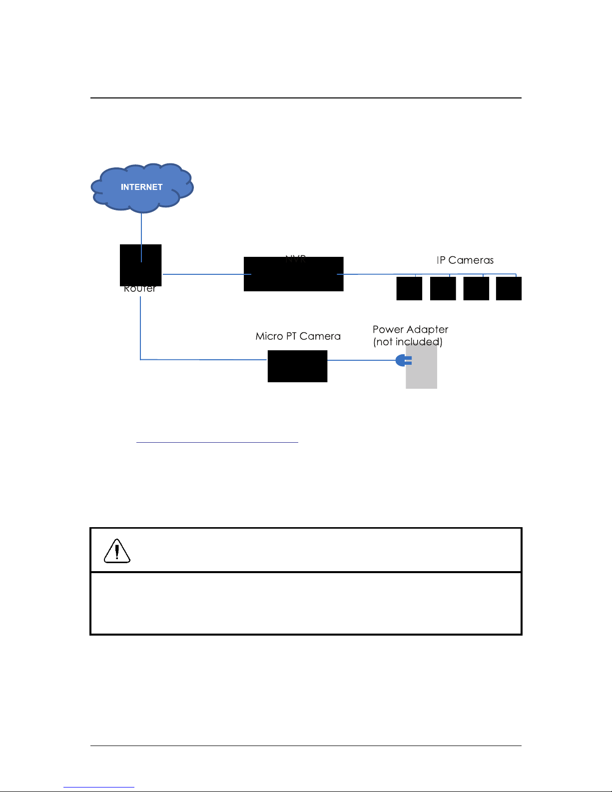
5.2 OPTION 2: Connecting Cameras to the Local Area Network
(LAN)
For flexibility, you may also connect the camera to the same Local
Area Network (LAN) as the NVR. This is accomplished by connecting
the camera to the same router as the NVR. For these installations, an
external PoE switch (sold separately) or power adapter (not included)
must be used to provide power to the camera. You also must add the
camera on the NVR before it will show a picture on the monitor or be
recorded by the NVR.
What is PoE?
PoE (Power over Ethernet) is a technology that allows Ethernet cables
to carry electrical power to connected devices. Compatible NVRs use
integrated PoE ports to provide power and Pan-Tilt commands to the
camera, as well as video connection to the NVR. In order to use PoE
with this IP camera, you must connect it directly to a compatible NVR
(Lorex LNR100 & LNR400 Series only) or a PoE switch on the same
network as the NVR.
PoE switches are available for purchase on www.lorextechnology.com
.
Complete the following steps to connect the camera to the NVR over
the LAN.
#; r. 1.0/19290/19290; en-US 7
Page 13

5 Connecting the Camera
Step 1 of 2 — OPTION A: Connecting the camera to your local
network using an optional PoE switch:
1. Connect an Ethernet cable of up to 300ft (91m) rated CAT5e or
higher (not included) from the LAN port on an external PoE switch
(sold separately on www.lorextechnology.com) to your router.
Connect the power cable to the PoE switch and to a power outlet
or surge protector.
Note
Terminology may vary depending on the model of PoE switch
you have.
2. Connect the camera to the PoE switch using the included Ethernet cable (or a CAT5e Ethernet cable of up to 300ft (91m)). The
PoE switch will provide power and video transmission the same
way as your NVR.
#; r. 1.0/19290/19290; en-US 8
Page 14
5 Connecting the Camera
Step 1 of 2 — OPTION B: Connecting the camera to your local
network using a power adapter (not included):
1. Connect the camera to a 12V DC power adapter (sold separately
on www.lorextechnology.com — model #: CVA4902).
2. Connect the camera to a router in the same network as your NVR
using the included Ethernet cable (or an Ethernet cable of up to
300ft (91m) rated CAT5e or higher).
Step 2 of 2: Add the camera to your NVR:
CAUTION
The following instructions are based on the Lorex LNR400 Series
NVR. See your NVR’s instruction manual for instructions on controlling the PTcamera with your system.
1. Right-click and select Device Search .
2. Log in using the admin account (default User Name: admin; default Password: 000000).
#; r. 1.0/19290/19290; en-US 9
Page 15

5 Connecting the Camera
3. Click Device Search. The system searches the network for compatible cameras.
4. Check the camera(s) you would like to add.
#; r. 1.0/19290/19290; en-US 10
Page 16

5 Connecting the Camera
5. Click Add. The Status indicator turns green to show the camera
is successfully connected.
6. Click OK to save changes.
Note
You can also add a camera to a specific channel by hovering the
mouse over an empty channel in split-screen view and clicking
. Then double-click the camera you would like to add and right
click to exit.
#; r. 1.0/19290/19290; en-US 11
Page 17

6 Installation
6.1 Installation Tips and Warnings
• Camera is rated for outdoor use. It is recommended to install the
camera in a sheltered area, such as under the eaves on a roof.
• Camera is capable of seeing in low light conditions (0.1 Lux), but it
cannot see in total darkness. It is recommended to install the camera where there is some ambient light (for example, street lighting
or starlight, moonlight, etc.) or leave some lighting on in the area
where the camera is installed.
• Mount the camera in a location that can support the camera
weight.
• Mount the camera where the lens is away from direct and intense
sunlight.
• Plan your cable wiring so that it does not interfere with power lines
or telephone lines.
• Ensure you adhere to local building codes.
• Ensure that the camera wiring is not exposed or easily cut.
• Mount the camera in an area that is visible but out of reach.
6.2 Installation (Indoor/Outdoor)
Note
The camera includes all necessary components for ceiling mounting only.
#; r. 1.0/19290/19290; en-US 12
Page 18

6 Installation
6.2.1 Ceiling Mounting
To ceiling mount the camera:
1. Use the included mounting template to mark holes for the mounting screws and camera cable.
1. Mounting screw holes; 2. Camera cable hole
2. Drill holes for the mounting screws, drywall anchors (optional)
and camera cable.
Note
• Use the included drywall anchors if installing on a drywall
surface.
• If you are planning on running the cables along the mounting surface, there is no need to drill a hole for the camera
cable.
#; r. 1.0/19290/19290; en-US 13
Page 19

6 Installation
3. Align the metal mounting plate so that the 3 screw holes in the
plate line up with the 3 holes drilled in the ceiling. Attach the flat
side of the metal mounting plate to the mounting surface using
the included mounting screws (3x).
1. Drywall anchors (3x — optional); 2. Mounting screws (3x); 3.
Mounting surface; 4. Metal mounting plate
4. Remove the M2x5 screw from the side of the camera using the included Allen key.
5. Connect the camera cables as shown in 5 Connecting the Cam-
era, page 6.
#; r. 1.0/19290/19290; en-US 14
Page 20
6 Installation
6. Align the 3 notches on the side of the dome camera with the pegs
on the metal mounting plate. Push the camera gently into the
mounting plate until it ‘clicks’.
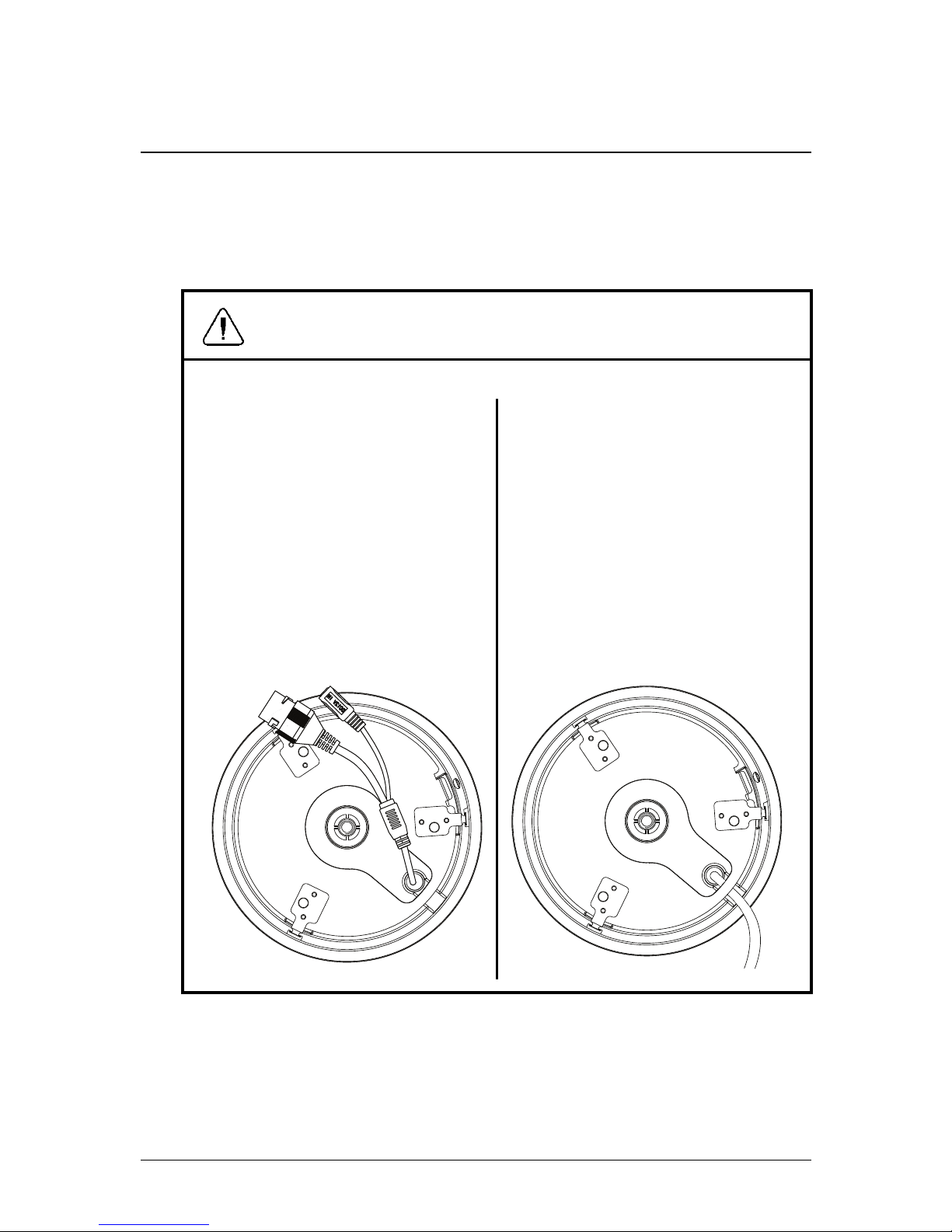
CAUTION
If you are drilling a hole for
the camera cable, ensure
that you run the cable
through the cable hole in
the metal mounting plate.
See image below for
reference:
If you run the cables along
the mounting surface, you
must run the cable through
the cable notch on the camera base and underneath
the metal mounting plate.
This will keep the camera
base flush to the surface
when mounted. See image
below for reference:
#; r. 1.0/19290/19290; en-US 15
Page 21

6 Installation
1. Pegs (x3); 2. Notches (x3)
Note
The pegs and notches only align one way. Do not force the
camera to fit into the metal mounting plate.
7. Re-insert the M2x5 screw removed in Step 4. Tighten firmly using
the included Allen key.
8. Remove the vinyl film from the dome cover once installation is
complete.
#; r. 1.0/19290/19290; en-US 16
Page 22

7 Controlling the PT Camera with an
NVR
The camera can accept Pan-Tilt commands directly through the
Ethernet cable. There is no need to run special wiring to control the
movement of the camera.
Note
• The following instructions are based on the Lorex LNR400 Series NVR. See your NVR’s instruction manual for instructions on
controlling the PTcamera with your system.
• For the latest list of compatible NVRs, please visit
www.lorextechnology.com/support.
To connect the camera to the system:
1. Connect the camera to your NVR as detailed in 5 Connecting the
Camera, page 6.
2. Right-click and click Main Menu. Enter the system user name
(default: admin) and password (default: 000000) if prompted.
#; r. 1.0/19290/19290; en-US 17
Page 23

7 Controlling the PT Camera with an NVR
3. Click
>Setting>Pan/Tilt/Zoom.
4. Under Channel, select the channel the micro PTcamera is connected to.
5. Under PTZ Type, select Remote.
6. Click OK. You can now control your micro PTcamera using the
system.
7.1 Controlling the Camera’s Pan-Tilt Movement (Local NVR)
1. In Live View, double-click the channel that has the camera connected to open in full-screen.
2. Right-click and click PTZ. Enter the system user name and password if prompted. The PTZ menu opens.
3. Use the on-screen controls to control the camera.
#; r. 1.0/19290/19290; en-US 18
Page 24
7 Controlling the PT Camera with an NVR
Pan-Tilt Controls
1. Direction keys: Click to pan and tilt the camera. Click SIT to stop
the current action.
2. Mouse PT: Click to activate mouse Pan-Tilt mode. In mouse
Pan-Tilt mode:
• Click and drag to move the camera.
• Use the scroll wheel to zoom in and out.
• Right-click to exit and return to normal Pan-Tilt controls.
3. Zoom/Focus/Iris: Click + / - next to Zoom to adjust the digital
zoom level (up to 3x digital zoom). Focus and iris settings are not
supported.
4. Advanced controls: Click to open advanced Pan-Tilt controls.
5. Not supported.
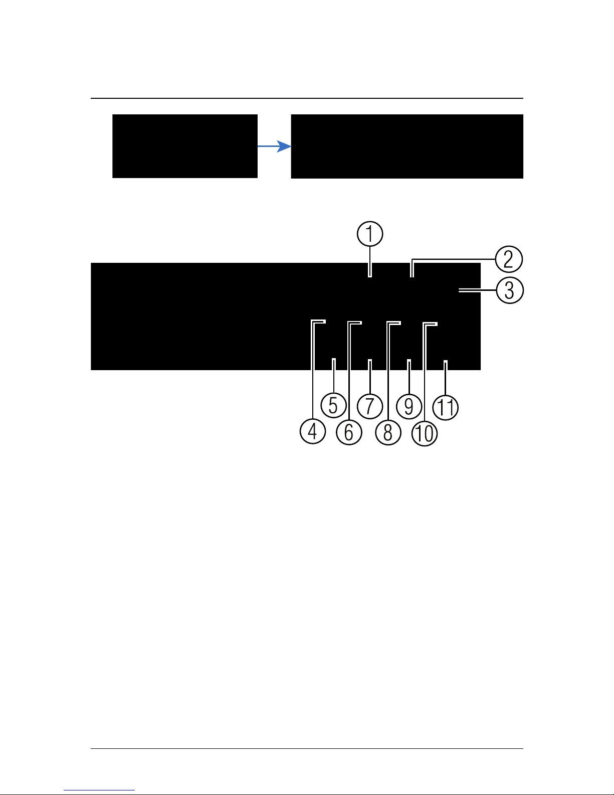
7.2 Advanced Pan-Tilt Controls
Advanced Pan-Tilt controls can be used to save camera positions
and cycle through various positions, and automate camera actions.
To open advanced Pan-Tilt controls:
• Click the arrow in the Pan-Tilt control window to open advanced
controls.
#; r. 1.0/19290/19290; en-US 19
Page 25
7 Controlling the PT Camera with an NVR
Advanced Pan-Tilt controls overview:
1. No.: Select the number of the action you want to perform.
2. Not supported.
3. Not supported.
4. Preset: Click to call the selected preset.
5. Not supported.
6. Not supported.
7. Not supported.
8. Not supported.
9. Not supported.
10. Not supported.
11. Aux: Click to open the aux menu, where you can set up Presets.
7.2.1 Presets
Presets will save a camera position for quick retrieval.
#; r. 1.0/19290/19290; en-US 20
Page 26

7 Controlling the PT Camera with an NVR
To add presets:
1. Click
to open the aux menu.
2. Click the Preset tab.
3. Enter the number of the preset you want to create under Preset.
4. Move the camera to the desired position and click Set.
To go to a preset:
• Under No., select the number of the preset you would like to go to
and click
.
7.2.2 Tour (Not Supported)
7.2.3 Pattern (Not Supported)
7.2.4 Border (Not Supported)
#; r. 1.0/19290/19290; en-US 21
Page 27

8 Technical Specifications
Image Sensor 1/3" 2.1MP
Video Format
NTSC / PAL
Effective Pixels 1920 (H) x 1080 (V)
Resolution Up to 1080p
Range ±180° Pan; 90° Tilt
Pan/Tilt Speed Max 100° / Sec (Preset)
Zoom 3x Digital Zoom
Min. Illumination 0.1 Lux in Black and White
Lens / Lens Type 3.6mm F1.2 / Fixed
Field of View
(Horizontal)
90°
Scan System
Progressive
Synchronization
Internal
Iris
AES
S / N Ratio >50dB (AGC Off)
Termination
RJ45 10 / 100M Ethernet
Power Requirement PoE (Power over Ethernet, Class 3)
1
;
12V DC
Power Consumption Max. 220mA
#; r. 1.0/19290/19290; en-US 22
1. Compatible with Lorex LNR100 & LNR400 Series only.
Page 28
8 Technical Specifications
Operating Temperature
Range
-4°F ~ 140°F / -20°C ~ 60°C
Operating Humidity
Range
Within 90%RH
Indoor/Outdoor Both (IP66)
2
Weight
0.25kg / 0.55lbs
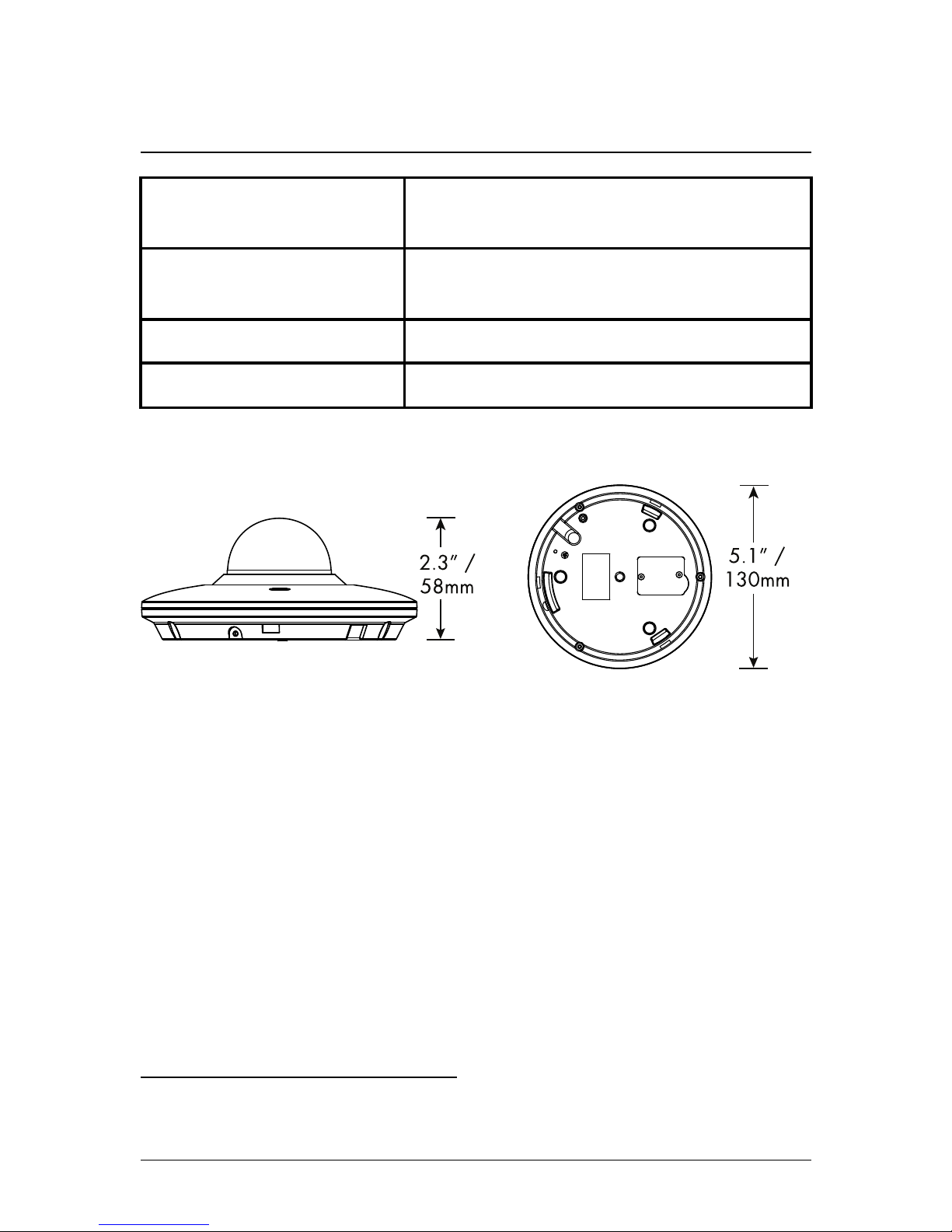
8.1 Dimensions
#; r. 1.0/19290/19290; en-US 23
2. Not intended for submersion in water. Installation in a sheltered location recommended.
Page 29

9 Troubleshooting
There is no picture at night.
• Camera is capable of seeing in extremely low light conditions (0.1
Lux), but it cannot see in total darkness. It is recommended to install the camera where there is some ambient light (e.g. street
lighting, starlight, moonlight, etc.) or leave a light on in the area
where the camera is installed.
No image at startup.
• The camera may take up to 1 minute to power up after being con-
nected to the NVR. Wait 2 minutes before following steps below.
• Check to ensure your camera is properly connected (see 5 Con-
necting the Camera, page 6).
• Ensure the camera is connected to a router on the same network
as the NVR.
• If the camera is connected to the LAN, you must search your net-
work for cameras using the NVR. See your NVR’s instruction manual for details.
• Make sure that the cable run is within the limitations specified in 5
Connecting the Camera, page 6. All Ethernet cables must be rated
CAT5e or higher.
• If using the power adapter, connect the power adapter to a differ-
ent outlet.
• Ethernet cable may be damaged or not connected properly. Check
your cable run or try a different cable.
• Reset the camera to factory default settings. See 10 Resetting the
Camera, page 26 for details.
No image or camera image is unclear.
• Dome cover is dirty. Clean the dome cover with a soft, slightly
damp cloth. Do not use anything other than water to clean the
dome cover, as chemicals such as acetone can permanently damage the plastic.
#; r. 1.0/19290/19290; en-US 24
Page 30

9 Troubleshooting
Image is distorted.
• Digital zoom is activated. Activating digital zoom may reduce the
resolution of the camera image. Zoom out completely to return to
the camera’s optimal resolution. See 7.1 Controlling the Camera’s
Pan-Tilt Movement (Local NVR), page 18 for instructions on using
the zoom controls.
• Image may become unclear when camera is tilted too close to the
camera base (e.g. pointed parallel to the ceiling). Tilt the camera
using the NVR or in the FLIR Cloud™ Client software or mobile
app.
Image is too bright.
• Ensure your camera isn’t pointed directly at a source of light (e.g.
sun or spot light).
• Check your NVR’s brightness and contrast settings.
• Move your camera to a different location.
Image is too dark.
• Check your NVR’s brightness and contrast settings.
• Move your camera to a different location.
NVR motion detection is constantly triggering.
• Turn off motion detection on the channel the micro PTcamera is
connected to. NVRs use video motion detection, which means
they detect motion by looking for changes between frames (images) in the video. If the camera is moving, the NVR will detect this
as motion.
#; r. 1.0/19290/19290; en-US 25
Page 31

10 Resetting the Camera
The camera features a hard reset button that is used to reset all camera settings back to their default values. This is useful in case you’ve
forgotten your login information or to revert camera image settings
back to their default values.
To reset the camera:
1. Separate the camera from the mounting plate if needed and disconnect camera cables.
2. Remove the 2 screws from the compartment cover on the camera
base using a Phillips screwdriver (not included).
#; r. 1.0/19290/19290; en-US 26
Page 32

10 Resetting the Camera
3. Press and hold the reset button for 4 seconds.
4. Replace the compartment cover on the camera base.
#; r. 1.0/19290/19290; en-US 27
Page 33

11 Notices
This product has been certified and found to comply with the limits
regulated by FCC, EMC, and LVD. Therefore, it is designated to provide reasonable protection against interference and will not cause interference with other appliance usage. However, it is imperative that
the user follows the guidelines in this manual to avoid improper usage, which may result in damage to the product, electrical shock and
fire hazard injury.
11.1 FCC/IC Notice
This equipment has been tested and found to comply with the limits
for a Class B digital device, pursuant to Part 15 of the FCC Rules.
These limits are designed to provide reasonable protection against
harmful interference in a residential installation. This equipment generates, uses, and can radiate radio frequency energy and, if not installed and used in accordance with the instruction, may cause
harmful interference to radio communications.
However, there is no guarantee that interference will not occur in a
particular installation. If this equipment does cause harmful interference to radio or television reception (which can be determined by
turning the equipment on and off), the user is encouraged to try to
correct the interference by one or more of the following measures:
1. Reorient or relocate the receiving antenna.
2. Increase the separation between the equipment and receiver.
3. Connect the equipment into an outlet on a circuit different from
that to which the receiver is connected.
4. Consult the dealer or an experienced radio or television technician for assistance.
11.2 Modification
Any changes or modifications not expressly approved by the grantee
of this device could void the user's authority to operate the device.
#; r. 1.0/19290/19290; en-US 28
Page 34

11 Notices
Toute modification non approuvée explicitement par le fournisseur de
licence de l'appareil peut entraîner l'annulation du droit de l'utilsateur
à utiliser l'appareil.
11.3 ROHS
This product is fully compliant with the European Union Restriction of
the Use of Certain Hazardous Substances in Electrical and Electronic
Equipment ("RoHS") Directive (2002/95/EC). The RoHS directive prohibits the sale of electronic equipment containing certain hazardous
substances such as lead, cadmium, mercury, and hexavalent chromium, PBB, and PBDE in the European Union.
#; r. 1.0/19290/19290; en-US 29
Page 35

last page
Publ. No.: LX400043
Release: 1.0
Commit:
19290
Head: 19290
Language: en-US
Modified: 2014-10-31
Formatted: 2014-11-05
Website
www.lorextechnology.com
Copyright
© 2014, Lorex Corporation
All rights reserved worldwide. Names and marks appearing herein
are either registered trademarks or trademarks of Lorex Corporation
and/or its subsidiaries. All other trademarks, trade names or company
names referenced herein are used for identification only and are the
property of their respective owners.
Legal disclaimer
As our product is subject to continuous improvement, Lorex
Corporation & subsidiaries reserve the right to modify product design,
specifications & prices without notice and without incurring any
obligation.E&OE.
Page 36

Manuel
d’utilisation
LNZ3522B
MICRO
CAMERA
DÔME HD PT
Page 37

Manuel d’utilisation
LNZ3522B MICRO CAMERA DÔME HD
PT
#; r. 1.0/20904/20904; fr-CA
Page 38

Merci d'avoir fait l'acquisition de ce produit. Lorex s'engage à
fournir à ses clients des solutions de sécurité fiables et de haute
qualité.
Ce manuel fait référence aux modèles suivants :
LNZ3522B
Visiter le site Internet pour consulter le plus récent manuel, pour
les téléchargements, pour les mises à jour du produit et pour en
savoir plus sur notre gamme complète d'accessoires à l'adresse :
www.lorextechnology.com
AVERTISSE-
MENT
RISQUE DE CHOC
ÉLECTRIQUE
NE PAS OUVRIR
AVERTISSEMENT : AFIN DE RÉDUIRE LE RISQUE
DE CHOC ÉLECTRIQUE, NE PAS RETIRER LE
COUVERCLE. LES PIÈCES INTERNES NE
PEUVENT PAS ÊTRE RÉPARÉES PAR
L'UTILISATEUR.
SE RÉFÉRER À UN TECHNICIEN QUALIFIÉ.
#; r. 1.0/20904/20904; fr-CA
Page 39

Le symbole de l'éclair dans un triangle
équilatéral est destiné à alerter l'utilisateur
de la présence d'une « tension
dangereuse » non isolée dans le boîtier du
produit qui pourrait être suffisamment
importante pour constituer un risque de
choc électrique.
Le point d'exclamation dans un triangle
équilatéral est destiné à alerter l'utilisateur
de la présence d'importantes directives
d'utilisation et de maintenance (entretien)
dans la documentation qui accompagne
l'appareil.
AVERTISSEMENT : NE PAS EXPOSER L'APPAREIL
À LA PLUIE OU À L'HUMIDITÉ AFIN D'ÉVITER LES
RISQUES D'INCENDIE OU DE CHOC ÉLECTRIQUE.
MISE EN GARDE : POUR ÉVITER LES CHOCS
ÉLECTRIQUES, JUMELER LA LARGE LAME DE LA
FICHE À LA LARGE FENTE ET L'INSÉRER
COMPLÈTEMENT.
#; r. 1.0/20904/20904; fr-CA
Page 40

Tables des matières
1 Mesures de sécurité ..... ... . . . . . . . . . . . . . . . . . . . ............ 1
2 LNZ3522B Caractéristiques....... . . . . . . . . . . . . . . . . . . . .. ... 2
3 Mise en route . . . . . . . . . .......................... ... .. . . . . . . . 4
4 Vue d’ensemble de la caméra. . . . . . .. ..................... 5
5 Branchement de la caméra.. .. . .. . . . . . . . . . . . . . . . . . . . ...... 6
5.1 OPTION 1 : Brancher les caméras à un
NVR........................ . . . . . . . . . . . . . . . . . . . .. ... 6
5.2 OPTION 2 : Connexion des caméras au
réseau local (LAN) . . . . . .. ......................... 7
6 Installation . . . . . . . . . . . . . . . . . . . ............................. .12
6.1 Conseils et avertissements
d’installation . . . . . . . . . . . . . . . . . . . . . . . ...............12
6.2 Installation (intérieur/extérieur)...................12
7 Commande de la caméra PTavec un NVR. .. . . . . . . .....17
7.1 Commander les fonctions panoramique
et inclinaison de la caméra (NVR
local) . . .. ....................... ... . . . . . . . . . . . . . . . .18
7.2 Commandes des fonctions panoramique
et inclinaison avancées ..................... . . . . .20
8 Spécifications techniques.................... . .. . . . . . . . . .23
8.1 Dimensions . . . . . . . . . . . . . .. ........................24
9 Dépannage..... ... . . . . . . . . . . . . . . . . . . . ......................25
10 Réinitialisation de la caméra. . . . . . .......................27
11 Avis .......... ... .. . . . . . . . . . . . . . . . . . . . .......................29
11.1 Avis FCC/Industrie Canada .. . . . . . .. .............29
11.2 Modification ....................... .. . . . . . . . . . . . . .30
11.3 ROHS........ . . . . . . . . . . . . . . . . . . . . . . ...............30
#; r. 1.0/20904/20904; fr-CA vii
Page 41

1 Mesures de sécurité
• Lire attentivement ce guide et le garder pour consultation
ultérieure.
• Suivre toutes les instructions pour une utilisation sécuritaire et manipuler avec soin.
• Utiliser la caméra à la température, au taux d’humidité et aux niveaux de tension précisés dans les spécifications techniques.
• La caméra est conçue pour un usage extérieur et est résistante
aux intempéries lorsqu’elle est bien installée. La caméra n’est pas
conçue pour être immergée dans l’eau. L’installation est recommandée dans un endroit couvert.
• Ne pas désassembler la caméra.
• Ne pas pointer votre caméra vers le soleil ou une source intense
de lumière.
• S’assurer d’installer la caméra dans un endroit pouvant supporter
le poids de la caméra.
• S’assurer qu’il n’y ait pas de câbles électriques sous tension à
l’endroit où la caméra sera fixée.
• Un nettoyage périodique peut s’avérer nécessaire. Utiliser un linge
humide seulement. Ne pas utiliser autre chose que de l’eau pour
nettoyer le couvercle du dôme, étant donné que les produits chimiques tels que l’acétone peuvent endommager le plastique de
manière permanente.
#; r. 1.0/20904/20904; fr-CA 1
Page 42

2 LNZ3522B Caractéristiques
• Résolution haute définition 1080p 2.1 MP capteur d’image1.
• Rotation panoramique de 360 pour une couverture absolue, avec
une vitesse de 100 par seconde.
• Forme micro dôme d’une dimension de 5 po (13 cm) de diamètre
et d’un peu plus de 2 po (5 cm) de hauteur.
• Offre 25 positions préréglées et programmables.
• Microphone intégré pour l’écoute audio.
• Objectif grand-angle de 3,6 mm avec champ de vue de 90 °.
• Un seul câble réseau pour la vidéo, l’alimentation et la commande
des fonctions panoramique et inclinaison.
• Définir des points de visionnement préréglés lorsque connecté à
un NVR
1
.
• Commande à distance de la caméra panoramique inclinable à
l’aide d’un téléphone intelligent ou d’une tablette, une fois
connecté à un NVR
1
.
• Le système de compensation du rétroéclairage Digital-Wide Dynamic Range garantit des images nettes dans des zones d’éclairage fort et faible.
• Réduction numérique de bruit 3D DNR pour des images nettes et
précises.
• Technologie d’imagerie ClearNight, pour des performances supérieures en conditions de faible luminosité
2
.
• Résistant aux intempéries pour une installation extérieure et intérieure (certifié IP66)
3
.
#; r. 1.0/20904/20904; fr-CA 2
Page 43

2 LNZ3522B Caractéristiques
• Fonctionne dans des températures extrêmes (de -4 °F à 140 °F /
de -20 °C à 60 °C).
• Boîtier métallique solide et durable résistant au vandalisme.
• Installation facile avec un câble d’alimentation par Ethernet CAT5e
(PoE).
• Le câble d’extension CAT5 PoE est fourni avec chaque caméra.
• Augmenter la portée du réseau avec un câble Ethernet allant jusqu’à 300 pi du NVR.
REMARQUE
1. Compatible avec le NVR HD de Lorex Gammes LNR100 et
LNR400 seulement.
2. Cette caméra possède un capteur d’images sensible à très
faible luminosité et par conséquent n’est pas doté de la fonctionnalité DEL infrarouge. La caméra nécessite une luminosité
ambiante (par exemple, une lumière de rue ou d’immeuble, la
lumière des étoiles ou de la lune) pour générer une image de
nuit. La caméra ne générera pas une image de nuit dans
l’obscurité totale (zéro lux) et par conséquent elle ne devrait
pas être installée dans des endroits totalement obscurs.
3. Ne pas immerger dans l’eau. Installation recommandée dans
un emplacement couvert.
#; r. 1.0/20904/20904; fr-CA 3
Page 44

3 Mise en route
Le système est livré avec les éléments suivants :
Micro caméra
dôme PT
Câble d’extension
Ethernet
Clé Allen
Plaque de montage
métallique
Modèle
d’assemblage
Vis de montage et
ancrages
(pour la plaque de
montage)
Manuel d’utilisation
#; r. 1.0/20904/20904; fr-CA 4
Page 45

4 Vue d’ensemble de la caméra
1. Couvercle du dôme
2. Port Ethernet : Brancher la caméra à un NVR ou allumer le PoE
du réseau à l’aide d’un câble Ethernet.
3. Alimentation 12 V CC Si aucun PoE n’est utilisé, brancher la ca-
méra sur une alimentation électrique de 12 V c.c. (non inclus).
Des adaptateurs d’alimentation pour cette caméra peuvent être
achetés sur www.lorextechnology.com (modèle numéro
CVA4902).
4. Objectif : Lentille de caméra.
5. Microphone : Microphone intégré.
6. Port GND : La vis préinsérée immobilise la caméra.
7. Compartiment du bouton de réinitialisation : Pour l’ouvrir, uti-
liser un tournevis Phillips pour faire apparaître le bouton de réinitialisation. Maintenir enfoncé 4 sec. afin de réinitialiser la caméra
#; r. 1.0/20904/20904; fr-CA 5
Page 46

5 Branchement de la caméra
REMARQUE
Il est recommandé de brancher la caméra au NVR et de tester les
commandes des fonctions panoramique et inclinaison avant l’installation permanente. Pour plus d’informations sur la configuration
des commandes des fonctions panoramique et inclinaison,
consulter 7 Commande de la caméra PTavec un NVR., page 17.
5.1 OPTION 1 : Brancher les caméras à un NVR
1. Brancher le connecteur Ethernet sur le câble de la caméra au
câble de rallonge Ethernet inclus.
2. Brancher la câble de rallonge Ethernet à l’un des ports PoE sur le
panneau arrière du NVR.
REMARQUE
Il est possible d’utiliser un seul câble Ethernet CAT5e jusqu’à
300 pi (91 m) pour brancher la caméra à votre NVR. La caméra
est compatible avec Lorex Gammes LNR100 et LNR400 NVR
seulement.
#; r. 1.0/20904/20904; fr-CA 6
Page 47

5 Branchement de la caméra
5.2 OPTION 2 : Connexion des caméras au réseau local (LAN)
Pour plus de flexibilité, on peut également connecter la caméra au
même réseau local (LAN) que le NVR. C’est réalisé en connectant la
caméra au même routeur que le NVR. Pour ces installations, un
commutateur externe PoE (vendu séparément) ou un adaptateur d’alimentation (non inclus) doit être utilisé pour fournir du courant à la caméra. Il faut aussi ajouter la caméra sur le NVR avant qu’elle montre
une image sur le moniteur ou qu’elle ne soit enregistrée par le NVR.
Qu’est-ce que le PoE ?
PoE (Power over Ethernet) est une technologie qui permet aux câbles
Ethernet d’amener l’alimentation aux dispositifs branchés. Les NVR
compatibles utilisent les ports PoE pour fournir l’alimentation à la caméra et permettre la commande des fonctions panoramique et inclinaison, ainsi que les connexions vidéos au NVR. Afin d’utiliser le PoE
avec cette caméra IP, il faut le connecter directement à un NVR
compatible (Lorex Gammes LNR100 et LNR400 uniquement) ou un
commutateur PoE sur le même réseau que le NVR.
Les commutateurs PoE peuvent être achetés sur
www.lorextechnology.com.
Procéder comme suit pour connecter la caméra au NVR par le réseau
LAN.
#; r. 1.0/20904/20904; fr-CA 7
Page 48

5 Branchement de la caméra
Étape 1 de 2 – OPTION A : Connexion de la caméra à votre réseau local en utilisant un commutateur PoE :
1. Brancher un câble Ethernet certifié CAT5e jusqu’à 300 pi (91 m)
ou supérieur (non inclus) de votre port LAN sur un commutateur
externe PoE (vendu séparément sur www.lorextechnology.com)
à votre routeur. Connecter le câble d’alimentation à l’interrupteur
PoE et le brancher dans la prise de courant ou au limiteur de
surtension.
REMARQUE
La terminologie peut varier selon le modèle de commutateur
PoE utilisé.
2. Brancher la caméra au commutateur PoE à l’aide du câble Ethernet inclus (ou un câble Ethernet CAT5e jusqu’à 300 pi (91 m)). Le
commutateur PoE peut procurer l’alimentation et la transmission
vidéo de la même manière que le NVR.
#; r. 1.0/20904/20904; fr-CA 8
Page 49

5 Branchement de la caméra
Étape 1 de 2 – OPTION B : Connexion de la caméra au réseau local en utilisant les adaptateurs d’alimentation (non inclus) :
1. Brancher la caméra à un adaptateur d’alimentation 12 V c.c.
(vendu séparément sur www.lorextechnology.com – modèle nu-
méro CVA4902).
2. Brancher la caméra à un routeur sur le même réseau que le NVR
en utilisant le câble Ethernet inclus (ou un câble Ethernet certifié
CAT5e jusqu’à 300 pi (91 m) ou supérieur).
Étape 2 de 2 : Ajout de la caméra au NVR :
ATTENTION
Les instructions suivantes s’appliquent au modèle Lorex LNR400
série NVR. Pour savoir comment commander les caméra PTavec
le système NVR, consulter le manuel du système NVR.
1. Faire un clic droit et sélectionner Rechercher un appareil.
2. Se connecter avec le compte d’administrateur (nom d’utilisateur
par défaut : admin; mot de passe par défaut : 000000).
#; r. 1.0/20904/20904; fr-CA 9
Page 50

5 Branchement de la caméra
3. Cliquer sur Rechercher un appareil. Le système cherche les
caméras prises en charge sur le réseau.
4. Cocher la/les caméra(s) à ajouter.
#; r. 1.0/20904/20904; fr-CA 10
Page 51

5 Branchement de la caméra
5. Cliquer sur Ajouter L’indicateur de statut devient vert si la caméra
est bien connectée.
6. Cliquer sur OK pour sauvegarder les changements.
REMARQUE
Il est possible d’ajouter une caméra à un canal particulier en plaçant le curseur sur un canal vide (en mode écran partagé) et en
cliquant
. Ensuite, double-cliquer sur la caméra que à ajouter
et cliquer avec le bouton droit de la souris pour sortir.
#; r. 1.0/20904/20904; fr-CA 11
Page 52

6 Installation
6.1 Conseils et avertissements d’installation
• La caméra est conçue pour être utilisée à l’extérieur. Il est recom-
mandé d’installer la caméra dans un endroit couvert, par exemple
sous l’avant-toit.
• La caméra peut filmer dans des conditions d’éclairage faibles
(0,1 lux), mais pas dans l’obscurité totale. Il est recommandé
d’installer la caméra dans un lieu ayant un peu de lumière ambiante (par exemple : éclairage de rue ou lumière provenant des
étoiles ou de la lune, etc.) ou de laisser un peu d’éclairage là où la
caméra est installée.
• Fixer la caméra dans un endroit pouvant supporter son poids.
• Fixer la caméra à un endroit où la lentille sera loin de la lumière di-
recte et intense du soleil.
• Planifier l’installation des câbles pour qu’ils n’interfère pas avec
les lignes de courant ou les lignes téléphoniques.
• S’assurer de respecter le code du bâtiment local.
• S’assurer que le câble de la caméra ne soit pas exposé ou coupé
facilement.
• Fixer la caméra dans un lieu visible, mais hors de portée.
6.2 Installation (intérieur/extérieur)
REMARQUE
La caméra rassemble tous les éléments nécessaires à une installation au plafond seulement.
#; r. 1.0/20904/20904; fr-CA 12
Page 53

6 Installation
6.2.1 Installation de la caméra au plafond
Pour installer la caméra au plafond :
1. Utiliser le gabarit de montage inclus afin de marquer l’emplacement des trous des vis de montage et des câbles de la caméra.
1. Trous des vis de montage ; 2 Trou du câble de la caméra
2. Percer les trous des vis de montage, des chevilles de la cloison
sèche (optionnel) et du câble de la caméra.
REMARQUE
• Si l’installation se fait sur une cloison sèche, utiliser les
chevilles pour cloison sèche (incluses).
• Si les câbles sont passés le long de la surface de montage, il n’est pas nécessaire de percer des trous pour les
câbles de la caméra.
#; r. 1.0/20904/20904; fr-CA 13
Page 54

6 Installation
3. Aligner le support de montage métallique de façon à ce que les
3 trous de vis dans la plaque s’alignent avec les 3 trous percés
dans le plafond. Attacher la partie plate de la plaque de montage
métallique à la surface de montage en utilisant les vis de montage inclus (3).
1. Chevilles de cloison sèche (3 – facultatives); 2. Trous des vis
de montage (3); 3. Surface de montage ; 4 Plaque de montage
métallique
4. Enlever la vis M2x5 sur le côté de la caméra avec la clé Allen
incluse.
5. Brancher les câbles de la caméra comme l’indique 5 Branche-
ment de la caméra, page 6.
#; r. 1.0/20904/20904; fr-CA 14
Page 55

6 Installation
6. Aligner les 3 encoches sur le côté de la caméra dôme avec les
broches sur la plaque de montage métallique. Ajuster délicatement la caméra dans la plaque de montage jusqu’à entendre un
« clic ».
ATTENTION
Si un trou est percé pour
faire passer le câble de la
caméra, faire passer le
câble à travers le trou prévu
à cet effet dans la plaque
de montage métallique. Voir
l’image de référence cidessous.
Si les câbles longent la surface de montage, les faire
passer dans l’encoche du
câble à la base de la caméra et sous la plaque de
montage métallique. Cela
gardera la caméra à niveau
sur la surface, lorsque montée. Voir l’image de référence ci-dessous.
#; r. 1.0/20904/20904; fr-CA 15
Page 56

6 Installation
1. Broches (3); 2. Encoches(3x)
REMARQUE
Les broches et les encoches s’alignent d’une seule manière.
Il ne faut pas forcer en ajustant la caméra dans la plaque de
montage métallique.
7. Réinsérer les vis M2x5 retirées à l’étape 4. Serrer fermement à
l’aide de la clé Allen incluse.
8. Retirer le film de protection en vinyle du couvercle du dôme une
fois l’installation terminée.
#; r. 1.0/20904/20904; fr-CA 16
Page 57

7 Commande de la caméra PTavec un
NVR.
La caméra peut accepter des commandes des fonctions panoramique et inclinaison directement à travers le câble Ethernet. Il n’est
pas nécessaire de passer un câblage spécial pour commander les
mouvements de la caméra.
REMARQUE
• Les instructions suivantes s’appliquent au modèle Lorex
LNR400 série NVR. Pour savoir comment commander les caméra PTavec le système NVR, consulter le manuel du
système NVR.
• Pour consulter la dernière liste à jour des NVR compatibles, visiter www.lorextechnology.com/support.
Pour connecter une caméra au système :
1. Connecter la caméra au NVR conformément à 5 Branchement
de la caméra, page 6.
2. Faire un clic droit, puis sélectionner le menu principal. Entrer le
nom d’utilisateur du système (par défaut : admin) et le mot de
passe (par défaut : 000000) si demandé.
#; r. 1.0/20904/20904; fr-CA 17
Page 58

7 Commande de la caméra PTavec un NVR.
3. Cliquer sur
> Réglages> Pan/Inclinaison/Zoom.
4. Sous Canal, sélectionner le canal sur lequel sera branchée la micro caméra PT
5. Sous Type PTZ, sélectionner À distance.
6. Cliquer sur OK. Il est maintenant possible de commander la micro caméra PTen utilisant le système.
7.1 Commander les fonctions panoramique et inclinaison de la
caméra (NVR local)
1. Dans Visionnement en direct, double-cliquer sur le canal sur lequel la caméra est connectée pour l’ouvrir en mode plein écran.
2. Faire un clic droit, puis cliquer sur PTZ Si demandé, entrer le
nom d’utilisateur et le mot de passe du système. Le menu PTZ
s’ouvre.
3. Utiliser les commandes apparaissant à l’écran pour manipuler la
caméra.
#; r. 1.0/20904/20904; fr-CA 18
Page 59

7 Commande de la caméra PTavec un NVR.
Commandes des fonctions panoramique et inclinaison
1. Touches de navigation : Cliquer pour faire tourner et basculer la
caméra. Cliquer SIT pour arrêter l’action en cours.
2. Souris PT : Cliquer pour activer le mode panoramique/inclinaison de la souris. Mode panoramique/inclinaison de la souris :
• Cliquer et faire glisser le curseur pour déplacer la caméra.
• Utiliser la roulette de défilement afin de faire un zoom avant
ou arrière.
• Cliquer sur le bouton droit de la souris pour sortir et revenir
aux commandes des fonctions panoramique et inclinaison
normales.
3. Zoom/Mise au point/Diaphragme : Cliquer + / - à côté de Zoom
afin d’ajuster le zoom numérique (zoom numérique jusqu’à 3x).
Les paramètres de configuration de la mise au point et du diaphragme ne sont pas fournis.
4. Contrôles avancés : Cliquer pour ouvrir les commandes des
fonctions panoramique et inclinaison avancées.
5. Non compatible.
#; r. 1.0/20904/20904; fr-CA 19
Page 60

7 Commande de la caméra PTavec un NVR.
7.2 Commandes des fonctions panoramique et inclinaison
avancées
Les commandes des fonctions panoramique et inclinaison avancées
peuvent être utilisées pour mémoriser des positions de la caméra et
pour passer d’une position à une autre, ainsi que pour automatiser les
actions de la caméra.
Pour ouvrir les commandes des fonctions panoramique et inclinaison avancées :
• Cliquer sur la flèche dans la fenêtre de commandes des fonctions
panoramique et inclinaison afin d’ouvrir les fonctions avancées.
Aperçu des commandes des fonctions panoramique et inclinaison avancées :
1. No.: Sélectionner le nombre d’actions à réaliser.
#; r. 1.0/20904/20904; fr-CA 20
Page 61

7 Commande de la caméra PTavec un NVR.
2. Non compatible.
3. Non compatible.
4. Prérégler : Cliquer pour activer le préréglage sélectionné.
5. Non compatible.
6. Non compatible.
7. Non compatible.
8. Non compatible.
9. Non compatible.
10. Non compatible.
11. Aux : Cliquer pour ouvrir le menu auxiliaire, où il est possible de
configurer les réglages.
7.2.1 Réglages
Les réglages permettent de mémoriser la position de la caméra pour
y revenir rapidement.
Pour ajouter des réglages :
1. Cliquer sur
pour ouvrir le menu auxiliaire.
2. Cliquer sur l’onglet réglages.
#; r. 1.0/20904/20904; fr-CA 21
Page 62

7 Commande de la caméra PTavec un NVR.
3. Saisir le numéro du réglage à créer sous Réglage.
4. Déplacer la caméra vers la position désirée et cliquer sur Régler.
Pour accéder a un réglage :
• Sous No., sélectionner le numéro du réglage à ouvrir, puis cliquer
sur
.
7.2.2 Tour (non compatible)
7.2.3 Modèle (non compatible)
7.2.4 Bord (non compatible)
#; r. 1.0/20904/20904; fr-CA 22
Page 63

8 Spécifications techniques
Capteur d’images 1/3 po 2.1 MP
Format vidéo NTSC / PAL
Pixels effectifs 1920 (H) x 1080 (V)
Résolution Jusqu’à 1080 p
Portée panoramique : ±180 °; inclinaison :
90 °
Vue panoramique/vitesse d’inclinaison
Max 100 °/sec (préréglé)
Zoom
Zoom numérique 3x
Illumination min 0,1 lux en noir et blanc
Lentille / type de lentille 3,6 mm F1,2 / Fixé
Champ de Vision
(horizontal)
90 °
Système de balayage Progressif
Synchronisation
Interne
Diaphragme
AES
Rapport S/B > 50 dB (CAG désactivé)
Terminaison
RJ45 10 / 100M Ethernet
Tension requise PoE (Power over Ethernet, Classe 3)
1
;
12 V c.c.
#; r. 1.0/20904/20904; fr-CA 23
1. Compatible avec Lorex LNR100 et LNR400 seulement.
Page 64

8 Spécifications techniques
Consommation
d’électricité
Max 220 mA
Plage de température
de fonctionnement
De -20 °C à 60 °C / -4 °F à 140 °F
Taux d’humidité de
fonctionnement
Dans les limites de 90 % d’humidité
relative
Intérieur/extérieur Les deux (IP66)
2
Poids
0,25 kg / 0,55 lb
8.1 Dimensions
#; r. 1.0/20904/20904; fr-CA 24
2. Ne pas immerger dans l’eau. Installation recommandée dans un emplacement couvert.
Page 65

9 Dépannage
Il n’y a pas d’image la nuit.
• La caméra peut filmer dans des conditions d’éclairage extrême-
ment faibles (0,1 lux), mais pas dans l’obscurité totale. Il est recommandé d’installer la caméra dans un lieu avec un peu de
lumière ambiante (par ex : éclairage de rue, lumière des étoiles,
lumière de la lune, etc.) ou de laisser une lumière allumée là où la
caméra est installée.
Pas d’image au démarrage.
• L’allumage de la caméra peut prendre jusqu’à une minute après
avoir connecté celle-ci au NVR. Attendre 2 minutes avant d’effectuer les étapes ci-dessous.
• S’assurer que la caméra est bien connectée (voir 5 Branchement
de la caméra, page 6).
• S’assurer que la caméra est connecté à un routeur sur le même
réseau que le NVR.
• Si la caméra est connectée au LAN, il faut rechercher dans le ré-
seau les caméras qui utilisent le NVR. Voir le manuel d’instruction
du NVR pour plus de renseignements.
• S’assurer que la longueur du câble respecte les limites précisées
dans 5 Branchement de la caméra, page 6. Tous les câbles Ethernet doivent être certifiés CAT5e ou supérieur.
• Si l’adaptateur d’alimentation est utilisé, le brancher à une prise
différente.
• Le câble Ethernet est peut-être endommagé ou n’est pas
connecté correctement. Vérifier le câble ou essayer un autre
câble.
• Restaurer les paramètres par défaut de la caméra. Consulter 10
Réinitialisation de la caméra, page 27 pour plus de détails.
Pas d’image ou une image trouble de la caméra.
• Le couvercle du dôme est sale. Nettoyer le couvercle du dôme
avec un tissu doux et légèrement humide. Ne pas utiliser autre
#; r. 1.0/20904/20904; fr-CA 25
Page 66

9 Dépannage
chose que de l’eau pour nettoyer le couvercle du dôme, étant
donné que les produits chimiques tels que l’acétone peuvent endommager le plastique de manière permanente.
L’image est déformée.
• Zoom numérique activé. L’activation du zoom numérique peut ré-
duire la résolution de l’image de la caméra. Dézoomer complètement pour revenir à une résolution optimale. Voir 7.1 Commander
les fonctions panoramique et inclinaison de la caméra (NVR local),
page 18 pour avoir les instructions sur la commande des zooms.
• L’image peut devenir trouble quand la caméra est inclinée trop
près de la base (p. ex., si elle est pointée parallèlement au plafond). Incliner la caméra en utilisant le NVR, le Client FLIR
Cloud™ software ou l’application mobile.
L’image est trop claire.
• S’assurer que la caméra ne pointe pas vers une source lumineuse
(p. ex., le soleil, un projecteur).
• Vérifier les paramètres de luminosité et de contraste du NVR
• Pointer la caméra à un autre endroit.
L’image est trop sombre.
• Vérifier les paramètres de luminosité et de contraste du NVR
• Pointer votre caméra à un autre endroit.
La détection de mouvement du NVR est constamment
déclenchée.
• Éteindre le détecteur de mouvement sur le canal sur lequel la ca-
méra PTest connectée. Les NVR utilisent la détection de mouvement vidéo, ce qui veut dire qu’ils détectent les mouvements en
cherchant des changements entre chaque image par seconde
(images) de la vidéo. Si la caméra est en mouvement, le NVR détectera cela comme un mouvement.
#; r. 1.0/20904/20904; fr-CA 26
Page 67

10 Réinitialisation de la caméra
La caméra est équipée d’un bouton de réinitialisation qui permet de
réinitialiser tous les paramètres de la caméra, afin de revenir aux valeurs par défaut. Ceci est utile en cas d’oubli des informations de
connexion ou pour rétablir les réglages d’image de la caméra aux valeurs par défaut.
Pour réinitialiser la caméra :
1. Si nécessaire, séparer la caméra de la plaque de montage et débrancher les câbles.
2. Enlever les deux vis du couvercle du compartiment à la base de
la caméra en utilisant le tournevis Phillips (non inclus).
#; r. 1.0/20904/20904; fr-CA 27
Page 68

10 Réinitialisation de la caméra
3. Maintenir enfoncé le bouton de ré-initialisation pendant
4 secondes.
4. Replacer le couvercle du compartiment à la base de la caméra.
#; r. 1.0/20904/20904; fr-CA 28
Page 69

11 Avis
Ce produit a été certifié et reconnu conforme aux limites règlementées par la FCC, l'EMC et le LVD. Par conséquent, il est conçu pour
fournir une protection raisonnable contre les interférences et ne causera pas d'interférence avec d'autres appareils en utilisation. Cependant, il est impératif que l'utilisateur suive les directives de ce manuel
pour éviter une utilisation inappropriée qui pourrait causer des dommages au produit, une décharge électrique et un risque d'incendie et
de blessures.
11.1 Avis FCC/Industrie Canada
Cet équipement a été examiné et s’est avéré conforme avec les limites pour un dispositif numérique de classe B, conformément à la partie 15 des règles de la FCC. Ces limites sont conçues pour assurer
une protection raisonnable contre l'interférence nocive dans une installation résidentielle. Cet équipement produit, utilise et peut émettre
de l'énergie de radiofréquence et s'il est non installé et utilisé selon
les instructions, peut causer de l'interférence nuisible aux
radiocommunications.
Cependant, il n'y a aucune garantie que l'interférence ne se produira
pas dans une installation particulière. Si cet équipement cause de l'interférence nuisible à la radio ou la réception des émissions télévisées, qui peut être déterminée en allumant ou éteignant
l'équipement, il est conseillé à l'utilisateur d'essayer de corriger l'interférence par une ou plusieurs des mesures suivantes :
1. Réorientez ou déplacez l'antenne de réception
2. Augmentez la distance entre l'équipement et le récepteur
3. Branchez l'équipement dans une sortie sur un circuit différent de
celui auquel le récepteur est branché
4. Consultez le revendeur ou un technicien expérimenté de radio/télévision pour de l'aide
#; r. 1.0/20904/20904; fr-CA 29
Page 70

11 Avis
11.2 Modification
Tout changement ou modification non expressément approuvé par la
garantie de cet appareil pourrait annuler le droit de l'utilisateur à utiliser l'appareil.
Toute modification non approuvée explicitement par le fournisseur de
licence de l'appareil peut entraîner l'annulation du droit de l'utilisateur
à utiliser l'appareil.
11.3 ROHS
Ce produit est entièrement conforme à la directive de l'Union européenne (2002/95/CE) sur la restriction de l'utilisation de certaines
substances dangereuses dans les équipements électriques et électroniques (« RoHS »). La directive RoHS interdit la vente de matériel
électronique contenant certaines substances dangereuses telles que
le plomb, le cadmium, le mercure et le chrome hexavalent, le PBB et
le PBDE dans l'Union européenne.
#; r. 1.0/20904/20904; fr-CA 30
Page 71

last page
Publ. No.: LX400043
Release: 1.0
Commit:
20904
Head: 20904
Language: fr-CA
Modified: 2014-11-20
Formatted: 2014-11-20
Site Web
www.lorextechnology.com
Droits dauteur
© 2014, Lorex Corporation
Tous droits réservés dans le monde entier. Les noms et les marques
figurant sur ce site Web sont des marques déposées ou des marques
commerciales de Lorex Corporation et/ou de ses filiales. Toutes les
autres marques, et tous les autres noms commerciaux ou noms de
société mentionnés dans ce site Web sont utilisé(e)s pour les seules
fins didentification et sont la propriété de leurs propriétaires respectifs.
Mentions légales
Étant donné que notre produit est soumis à une amélioration continue,
Lorex Corporation et ses filiales se réservent le droit de modifier la
conception, les spécifications et les prix de ce produit sans préavis et
sans encourir aucune obligation. E&OE.
Page 72

Manual de
instrucciones
CÁMARA
LNZ3522B HD
MICRO PT
DOME
Page 73

Manual de instrucciones
CÁMARA LNZ3522B HD MICRO PT
DOME
#; r. 1.0/19724/19724; es-MX
Page 74

Gracias por comprar este producto. Lorex se compromete a
brindar a nuestros clientes una solución de seguridad confiable de
alta calidad.
Este manual se refiere a los siguientes modelos:
LNZ3522B
Para obtener el último manual en línea, descargas o
actualizaciones de productos o si desea conocer nuestra línea
completa de productos accesorios, ingrese a nuestro sitio web:
www.lorextechnology.com
ADVERTENCIA
RIESGO DE
CHOQUE
ELÉCTRICO
NO ABRIR
ADVERTENCIA: PARA REDUCIR EL RIESGO DE
CHOQUE ELÉCTRICO, NO QUITAR LA TAPA. NO
CONTIENE PARTES SUJETAS A MANTENIMIENTO.
EL MANTENIMIENTO O SERVICIO DEBE ESTAR A
CARGO DE PERSONAL CALIFICADO.
#; r. 1.0/19724/19724; es-MX
Page 75

El símbolo del rayo con la punta en flecha
dentro de un triángulo equilátero pretende
alertar al usuario sobre la presencia de un
"voltaje peligroso" sin aislación dentro de la
carcasa del producto, que puede ser de tal
magnitud que suponga un riesgo de
choque eléctrico.
El signo de exclamación dentro de un
triángulo equilátero pretende alertar al
usuario sobre la presencia de
instrucciones de mantenimiento (servicio)
y operación importantes en la literatura que
acompaña al dispositivo.
ADVERTENCIA: PARA EVITAR EL PELIGRO DE
INCENDIO O CHOQUE, NO EXPONGA ESTA
UNIDAD A LA LLUVIA O LA HUMEDAD.
PRECAUCIÓN: PARA EVITAR CHOQUES
ELÉCTRICOS, CONECTE LA PATA ANCHA DEL
ENCHUFE A LA RANURA ANCHA E INSÉRTELA
COMPLETAMENTE.
#; r. 1.0/19724/19724; es-MX
Page 76

Tabla de contenido
1 Instrucciones de seguridad.......................... .. . . . 1
2 LNZ3522B Características . . . . . . . . . . . . .. .................. 2
3 Instrucciones iniciales. . . . . . . . . . . . . . .. ..................... 4
4 Descripción general de la cámara. .. . . . . . . . . . . . . . . . . .. ... 5
5 Cómo conectar la cámara ......... . . . . . . . . . . . . . . . . . . . .. ... 6
5.1 OPCIÓN 1: Cómo conectar las cámaras
a una NVR . . . . . . . .. .......................... . . . . . . 6
5.2 OPCIÓN 2: Conexión de cámaras a la
red de área local (LAN) .... .. . .. . . . . . . . . . . . . . . . . . . 6
6 Instalación . . . . . . . . . . . . . . . . .. .......................... . .. . .12
6.1 Consejos y advertencias de
instalación ........................ . . . . . . . . . . . . . . . .12
6.2 Instalación (interiores/exteriores) . . . . . . . . .. ......12
7 Cómo controlar la cámara PTcon una NVR . . . . . . . .....17
7.1 Cómo controlar el movimiento P-T de la
cámara (NVR local) .............. . . . . . . . . . . . . . . . .18
7.2 Controles de P/Tavanzados ..... . . . . . . . . . . . . . . . .19
8 Especificaciones técnicas . . .. .......................... .23
8.1 Dimensiones...................... . .. . . . . . . . . . . . . .24
9 Resolución de problemas .......... .. . .. . . . . . . . . . . . . . . . . .25
10 Cómo restablecer la cámara .................. ... .. . . . . . .27
11 Notificaciones . ... . . . . . . . . . . . . . . . . . . . ......................29
11.1 Notificación de FCC/IC. . . . . ......................29
11.2 Modificación . . . . . . . . . ............................ .30
11.3 ROHS........ . . . . . . . . . . . . . . . . . . . . . . ...............30
#; r. 1.0/19724/19724; es-MX vii
Page 77

1 Instrucciones de seguridad
• Lea esta guía con cuidado y guárdela para referencias futuras.
• Siga todas las instrucciones para el uso seguro del producto y
manipúlelo con cuidado.
• Use la cámara dentro de la temperatura indicada, la humedad y
los niveles de voltaje indicados en las Especificaciones técnicas.
• La cámara está diseñada para uso en exteriores y es resistente a
la intemperie cuando está instalada correctamente. La cámara no
está diseñada para sumergirse en agua. Se recomienda su instalación en un ambiente resguardado.
• No desarme la cámara.
• No apunte la cámara directamente hacia el sol o fuentes de luz
intensa.
• Asegúrese de instalar la cámara en una ubicación que pueda resistir el peso de la cámara.
• Asegúrese de que no haya cables eléctricos con corriente en el
área donde planea instalar la cámara.
• Es posible que se requiera una limpieza periódica. Utilice solamente un paño humedecido. No utilice nada que no sea agua para limpiar la cubierta tipo domo, ya que los productos químicos
tales como la acetona pueden dañar permanentemente el plástico.
#; r. 1.0/19724/19724; es-MX 1
Page 78

2 LNZ3522B Características
• Sensor de imagen con resolución de 2.1 MP y alta definición de
1080p.
1
• Rotación horizontal completa de 360° para lograr una cobertura
de área completa y una velocidad horizontal de 100 grados por
segundo.
• Factor de forma de micro domo de solo 5" de diámetro y 2" de alto.
• 25 posiciones predefinidas programables.
• Micrófono incorporado para escuchar audio.
• Lente de ángulo amplio de 3,6 mm con campo de visión de 90°.
• Configuración para un solo cable de red para video, energía y
control de tomas panorámicas/inclinación.
• Programación de puntos de visualización preestablecidos cuando
se conecta con un NVR compatible.
1
• Control remoto de la cámara P/T por medio de un teléfono inteligente o tablet cuando está conectada a un NVR compatible.
1
• El ajuste de amplio rango dinámico digital garantiza imágenes claras en las áreas de luz alta y baja.
• Reducción de ruido digital 3D DNR para imágenes claras y
precisas.
• Tecnología de imagen ClearNight para un mejor rendimiento en
condiciones de poca luz.
2
• Resistente a la intemperie para instalaciones en interiores y exteriores (calificación IP66).
3
#; r. 1.0/19724/19724; es-MX 2
Page 79

2 LNZ3522B Características
• Rendimiento en temperaturas extremas (–4 °F ~ 140 °F / –20 °C ~
60 °C).
• Carcasa de metal de gran resistencia y duración, resistente a
daños.
• Fácil instalación con encendido a través de cable Ethernet (PoE)
Cat5.
• Cada cámara incluye el cable de extensión CAT5 PoE.
• Amplíe su cobertura con el cable Ethernet hasta 300’ desde la
NVR.
NOTA
1. Compatible con Lorex HD NVR Series LNR100 y LNR400,
únicamente.
2. Esta cámara incluye un sensor de imágenes sensible en condiciones de luz ultrabaja y, por lo tanto, no incluye ledes infrarrojos. La cámara requiere iluminación ambiental (por
ejemplo, iluminación de la calle o del edificio, luz de las estrellas o luz de luna) para ofrecer una imagen nocturna. En oscuridad total (cero Lux), la cámara no producirá ninguna imagen
nocturna, de modo que no debe instalarse en áreas completamente oscuras.
3. No están diseñadas para sumergirse en el agua. Se recomienda la instalación en una ubicación resguardada.
#; r. 1.0/19724/19724; es-MX 3
Page 80

3 Instrucciones iniciales
El sistema viene con los siguientes componentes:
Cámara Micro PT
Dome
Cable de extensión
Ethernet
Llave Allen
Placa de montaje
metálica
Plantilla de montaje
Tornillos de montaje
y anclajes
(para placa de
montaje)
Manual de
instrucciones
#; r. 1.0/19724/19724; es-MX 4
Page 81

4 Descripción general de la cámara
1. Cubierta en forma de domo
2. Puerto Ethernet: Conecte la cámara a una NVR o a un interrup-
tor PoE en su red con el cable Ethernet incluido.
3. Potencia de DC de 12 V: Si no utiliza un PoE, conecte la cámara
a una fuente de alimentación de 12 V CC (no viene incluido). Los
adaptadores de corriente de esta cámara están disponibles para
su compra en www.lorextechnology.com (modelo N.°: CVA4902).
4. Lente: Lente de la cámara
5. Micrófono: Micrófono incorporado
6. Puerto GND: El tornillo preinsertado conecta la cámara a tierra.
7. Compartimiento del botón de reinicio: Ábralo con un desar-
mador Phillips para encontrar el botón Restablecer. Presiónelo y
manténgalo presionado durante 4 segundos para restablecer la
configuración de la cámara.
#; r. 1.0/19724/19724; es-MX 5
Page 82

5 Cómo conectar la cámara
NOTA
Se recomienda conectar la cámara a su NVR y probar los controles P-Tantes de una instalación permanente. Para obtener las instrucciones sobre cómo configurar los controles P-T, consulte 7
Cómo controlar la cámara PT con una NVR, página 17.
5.1 OPCIÓN 1: Cómo conectar las cámaras a una NVR
1. Conecte el conector Ethernet del cable de la cámara al cable de
extensión Ethernet incluido.
2. Conecte el cable de extensión Ethernet a uno de los puertos PoE
que están en el panel trasero de la NVR.
NOTA
Puede usar un solo cable 300 pies (91 m) Ethernet CAT5e para
conectar la cámara a la NVR. La cámara es compatible con Lorex
Series LNR100 y LNR400 NVR únicamente.
5.2 OPCIÓN 2: Conexión de cámaras a la red de área local
(LAN)
Para una mayor flexibilidad, también puede conectar la cámara a la
misma red de área local (LAN), como la NVR. Esto se logra mediante
#; r. 1.0/19724/19724; es-MX 6
Page 83

5 Cómo conectar la cámara
la conexión de la cámara al mismo enrutador de la NVR. Para estas
instalaciones, debe usarse un interruptor externo PoE (se vende por
separado) o el adaptador de corriente (no incluido) para proveer de
energía a la cámara. También debe agregar la cámara en la NVR antes de que esta muestre una imagen en el monitor o que la NVR
grabe.
¿Qué es PoE?
PoE (alimentación a través de Ethernet) es una tecnología que permite que los cables Ethernet transmitan energía eléctrica a los dispositivos conectados. Las NVR compatibles utilizan puertos PoE
integrados para suministrar energía y comandos P-T a la cámara, así
como la conexión de video a la NVR. Para utilizar PoE en esta cámara IP, debe conectarla directamente a una NVR compatible (solo Lorex Series LNR100 y LNR400) o a un interruptor PoE que esté en la
misma red que la NVR.
Los interruptores PoE están disponibles para su compra en
www.lorextechnology.com.
Siga los pasos a continuación para conectar la cámara a la NVR a
través de LAN.
#; r. 1.0/19724/19724; es-MX 7
Page 84

5 Cómo conectar la cámara
Paso 1 de 2 — OPCIÓN A: Conexión de la cámara a la red local
mediante un interruptor PoE opcional:
1. Conecte un cable Ethernet con clasificación hasta 300 pies
(91 m) CAT5e o superior (no incluido) desde el puerto LAN del interruptor externo PoE (se vende por separado en
www.lorextechnology.com) hasta el enrutador. Conecte el cable
de corriente al interruptor PoE y a una conexión eléctrica o regulador de tensión.
NOTA
La terminología puede variar según el modelo de interruptor
PoE que tenga.
2. Conecte la cámara al interruptor PoE mediante el cable Ethernet
incluido (o un cable Ethernet CAT5e de hasta 300 pies (91 m)).
El interruptor PoE proporcionará energía y transmisión de video
de la misma forma que lo hace su NVR.
#; r. 1.0/19724/19724; es-MX 8
Page 85

5 Cómo conectar la cámara
Paso 1 de 2 — OPCIÓN B: Cómo conectar la cámara a su red local con un adaptador de corriente (no incluido):
1. Conecte la cámara a un adaptador de corriente de 12 V CC (se
vende por separado en www.lorextechnology.com — modelo N.°:
CVA4902).
2. Conecte la cámara a un enrutador que esté en la misma red que
la NVR mediante el cable Ethernet incluido (o un cable Ethernet
de hasta 300 pies (91 m) con clasificación CAT5e o superior).
Paso 2 de 2: Agregue la cámara a su NVR:
ATENCIÓN
Las siguientes instrucciones se basan en la NVR de serie Lorex
LNR400. Consulte su manual de instrucciones para obtener instrucciones sobre cómo controlar la cámara PTcon su sistema.
1. Haga clic derecho y seleccione Buscar dispositivo.
2. Inicie sesión a través de la cuenta de admin (Nombre de usuario
predeterminado: admin; Contraseña predeterminada: 000000).
#; r. 1.0/19724/19724; es-MX 9
Page 86

5 Cómo conectar la cámara
3. Haga clic en Buscar dispositivo. El sistema busca en la red las
cámaras compatibles.
4. Marque las cámaras que desea agregar.
#; r. 1.0/19724/19724; es-MX 10
Page 87

5 Cómo conectar la cámara
5. Haga clic en Agregar. El indicador de estado se torna verde para
mostrar que la cámara ha sido conectada exitosamente.
6. Haga clic en OK para guardar los cambios.
NOTA
También puede añadir una cámara a un canal específico, con solo
pasar el ratón sobre un canal vacío en la vista de pantalla dividida
y hacer clic en
. Luego, haga doble clic en la cámara que de-
see agregar y haga clic derecho para salir.
#; r. 1.0/19724/19724; es-MX 11
Page 88

6 Instalación
6.1 Consejos y advertencias de instalación
• La cámara está diseñada para uso en exteriores. Se recomienda
instalar la cámara en un área resguardada, como debajo del alero
del techo.
• La cámara es capaz de captar imágenes en condiciones de luz
baja (0.1 Lux) pero no puede captar imágenes en la oscuridad total. Se recomienda instalar la cámara donde haya algo de luz ambiental (p. ej., luz de la calle, las estrellas, la luna, etc.) o puede
dejar alguna luz encendida en el área donde se instale la cámara.
• Monte la cámara en una ubicación que pueda resistir el peso de
la cámara.
• Monte la cámara en lugares donde el lente esté lejos de la luz so-
lar directa e intensa.
• Planee su cableado para que no interfiera con las líneas eléctricas
o las líneas telefónicas.
• Asegúrese de cumplir con los códigos de la construcción locales.
• Asegúrese de que el cableado de la cámara no esté expuesto o
que se pueda cortar con facilidad.
• Monte la cámara en un área que sea visible pero que esté fuera
del alcance.
6.2 Instalación (interiores/exteriores)
NOTA
La cámara incluye todos los componentes necesarios para el
montaje sobre el techo, únicamente.
#; r. 1.0/19724/19724; es-MX 12
Page 89

6 Instalación
6.2.1 Montaje en techo
Para montar la cámara en el techo:
1. Use la plantilla de montaje incluida para marcar los orificios donde colocará los tornillos de montaje y el cable de la cámara.
1. Orificios para tornillos de montaje; 2. Orificio para el cable de
la cámara
2. Perfore orificios para tornillos de montaje, tapetes para yeso (opcional) y cable de la cámara.
NOTA
• Use los taquetes para yeso incluidos si la instalación se
hace en una superficie de yeso laminado.
• Si planea pasar los cables a lo largo de la superficie de
montaje, no es necesario perforar un orificio para el cable
de la cámara.
#; r. 1.0/19724/19724; es-MX 13
Page 90

6 Instalación
3. Alinee la placa de montaje metálica de manera que los 3 orificio
para tornillos que se encuentran en la placa se alineen con los 3
orificios perforados en el techo. Fije el lado plano de la placa de
montaje metálica contra la superficie de montaje con los tornillos
de montaje incluidos (3x).
1. Tapetes para yeso (3x — opcional); 2. Tornillos de montaje
(3x); 3. Superficie de montaje; 4. Placa de montaje metálica
4. Retire el tornillo M2x5 del lateral de la cámara con la llave hexagonal que viene incluida.
5. Conecte los cables de la cámara, como se muestra en 5 Cómo
conectar la cámara, página 6.
#; r. 1.0/19724/19724; es-MX 14
Page 91

6 Instalación
6. Alinee las 3 ranuras ubicadas en el lateral de la cámara domo
con las clavijas que se encuentran en la placa de montaje metálica. Empuje la cámara suavemente hacia el interior de la placa de
montaje hasta que se escuche un "clic".
ATENCIÓN
Si perfora un orificio para el
cable de la cámara, asegúrese de pasar el cable a través del orificio para el cable
ubicado en la placa de
montaje metálica. Observe
la imagen que aparece a
continuación para su
referencia:
Si pasa los cables a lo largo
de la superficie de montaje,
debe pasarlos a través de
la ranura para el cable que
se encuentra en la base de
la cámara y por debajo de
la placa de montaje metálica. Esto hará que la base
de la cámara quede al ras
de la superficie cuando esté
montada. Observe la imagen que aparece a continuación para su referencia:
#; r. 1.0/19724/19724; es-MX 15
Page 92

6 Instalación
1. Clavijas (x3); 2. Ranuras (x3)
NOTA
Las clavijas y ranuras se alinean de una sola manera. No
fuerce la cámara para que encaje en la placa de montaje
metálica.
7. Vuelva a insertar el tornillo M2x5 que retiró en el Paso 4. Ajústelo
firmemente con la llave hexagonal que viene incluida.
8. Retire la película de vinilo de la cubierta tipo domo una vez completa la instalación.
#; r. 1.0/19724/19724; es-MX 16
Page 93

7 Cómo controlar la cámara PTcon
una NVR
La cámara puede admitir comandos P-T directamente a través del
cable Ethernet. No es necesario tender un cableado especial para
controlar el movimiento de la cámara.
NOTA
• Las siguientes instrucciones se basan en la NVR de serie Lorex LNR400. Consulte su manual de instrucciones para obtener instrucciones sobre cómo controlar la cámara PTcon su
sistema.
• Para acceder a la lista de las últimas cámaras compatibles
con NVR, visite www.lorextechnology.com/support.
Para conectar una cámara al sistema:
1. Conecte la cámara a la NVR como se detalla en 5 Cómo conectar la cámara, página 6.
2. Haga clic con el botón derecho y luego haga clic en Menú principal. Ingrese el nombre de usuario del sistema (predetermina-
do: admin) y la contraseña (predeterminada: 000000) si se le
solicita.
#; r. 1.0/19724/19724; es-MX 17
Page 94

7 Cómo controlar la cámara PTcon una NVR
3. Haga clic en
>Ajustes>PTZ.
4. En Canal, seleccione el canal en el que está conectada la cámara PT.
5. En Tipo de PTZ, seleccione Remoto.
6. Haga clic en OK. Ahora puede controlar su cámara micro PTcon
el sistema.
7.1 Cómo controlar el movimiento P-T de la cámara (NVR
local)
1. En la visualización en vivo, haga doble clic en el canal al que está
conectada la cámara para abrir en modo de pantalla completa.
2. Haga clic derecho y luego haga clic en PTZ. Ingrese el nombre
de usuario del sistema y la contraseña si se le solicita. Se abrirá
el menú PTZ.
3. Utilice los controles de la pantalla para controlar la cámara.
#; r. 1.0/19724/19724; es-MX 18
Page 95

7 Cómo controlar la cámara PTcon una NVR
Control de P/T
1. Teclas de dirección: Haga clic para desplazar e inclinar la cá-
mara. Haga clic en SIT para detener la acción actual.
2. PT por mouse: Haga clic para activar el modo PT por mouse. En
el modo P-T por mouse:
• Haga clic y arrastre para mover la cámara.
• Utilice la rueda de desplazamiento para acercar y alejar.
• Haga clic con el botón derecho del mouse para salir y regre-
sar a los controles PT normales.
3. Zoom/Enfoque/Iris: Haga clic en + / - que se encuentra al lado
del Zoom para ajustar el nivel de zoom digital (hasta un zoom digital de 3x). No admite enfoque ni configuración de iris.
4. Controles avanzados: Haga clic para abrir los controles PT
avanzados.
5. No compatible.
7.2 Controles de P/Tavanzados
Los controles de PTavanzados pueden utilizarse para guardar las posiciones de la cámara y cambiar entre varias posiciones, y automatizar las acciones de la cámara.
Para abrir los controles PT avanzados:
#; r. 1.0/19724/19724; es-MX 19
Page 96

7 Cómo controlar la cámara PTcon una NVR
• Haga clic en la flecha que se encuentra en la ventana de control
de PT para abrir los controles avanzados.
Descripción general de los controles de P/Tavanzados:
1. N.º: Seleccione el número de la acción que desea realizar.
2. No compatible.
3. No compatible.
4. Predefinir: Haga clic para establecer la predefinición
seleccionada.
5. No compatible.
6. No compatible.
7. No compatible.
8. No compatible.
9. No compatible.
10. No compatible.
#; r. 1.0/19724/19724; es-MX 20
Page 97

7 Cómo controlar la cámara PTcon una NVR
11. Aux: Haga clic para abrir el menú auxiliar, donde puede configurar las posiciones predeterminadas.
7.2.1 Predefiniciones
Las predefiniciones guardarán una posición de la cámara para poder
recuperarla rápidamente.
Para agregar las predefiniciones:
1. Haga clic en
para abrir el menú auxiliar.
2. Haga clic en la pestaña Predefinir.
3. Ingrese el número de predefiniciones que desea crear debajo de
Predefinir.
4. Mueva la cámara hacia la posición deseada y haga clic en
Definir.
Para ir a un preestablecido:
• En n.°, seleccione el número de predefiniciones al que desearía
acceder y haga clic en
.
#; r. 1.0/19724/19724; es-MX 21
Page 98

7 Cómo controlar la cámara PTcon una NVR
7.2.2 Recorrido (no admitido)
7.2.3 Patrón (no admitido)
7.2.4 Borde (no admitido)
#; r. 1.0/19724/19724; es-MX 22
Page 99

8 Especificaciones técnicas
Sensor de imagen 1/3" 2.1MP
Formato de video
NTSC / PAL
Píxeles efectivos 1920(H) x 1080 (V)
Resolución Hasta 1080p
Rango ±Vista panorámica de 180°; inclinación
de 90°
Velocidad de toma horizontal o inclinación
Máx. de 100° / Seg. (predefinido)
Zoom Zoom digital de 3x
Iluminación mín. 0,1 Lux en blanco y negro
Lente/tipo de lente 3,6 mm F1.2 / Fijo
Campo de visión
(Horizontal)
90°
Sistema de escáner Progresivo
Sincronización Interno
Iris
AES
Relación señal-ruido >50dB (AGC desactivado)
Terminación RJ45 10 / 100M Ethernet
Requerimiento de
corriente
PoE (alimentación a través de Ethernet, clase 3)
1
; 12 V DC
Consumo de energía Máx. 220 mA
#; r. 1.0/19724/19724; es-MX 23
1. Compatible con las series Lorex LNR100 y LNR400, únicamente.
Page 100

8 Especificaciones técnicas
Rango de temperatura
para funcionamiento
-4 °F ~ 140 °F / -20 °C ~ 60 °C
Intervalo de humedad
de operación
dentro de 90 % HR
Interiores/Exteriores Ambos (IP66)
2
Peso 0,25 kg / 0,55 libras
8.1 Dimensiones
#; r. 1.0/19724/19724; es-MX 24
2. No están diseñadas para sumergirse en el agua. Se recomienda la instalación en una
ubicación resguardada.
 Loading...