

Lorex LNZ32P4 SERIES Instruction Manual

Instruction
Manual
LNZ32P4 SERIES
4x IP PTZ DOME
CAMERA
LNZ32P4_MANUAL_TRILINGUAL_R2
Thank you for purchasing this product. Lorex is committed to providing our customers with
a high quality, reliable security solution.
This manual refers to the following model:
LNZ32P4
For the latest online manual, downloads and product updates, and to learn about our
complete line of accessory products, please visit our website at:
www.lorextechnology.com
WARNING
RISK OF ELECTRIC SHOCK
DO NOT OPEN
WARNING: TO REDUCE THE RISK OF ELECTRIC SHOCK DO NOT
REMOVE COVER. NO USER SERVICEABLE PARTS INSIDE.
REFER SERVICING TO QUALIFIED SERVICE PERSONNEL.
The lightning flash with arrowhead symbol, within an
equilateral triangle, is intended to alert the user to the
presence of uninsulated "dangerous voltage" within the
product’s enclosure that may be of sufficient magnitude to
constitute a risk of electric shock.
The exclamation point within an equilateral triangle is
intended to alert the user to the presence of important
operating and maintenance (servicing) instructions in the
literature accompanying the appliance.
WARNING: TO PREVENT FIRE OR SHOCK HAZARD, DO NOT EXPOSE
THIS UNIT TO RAIN OR MOISTURE.
CAUTION: TO PREVENT ELECTRIC SHOCK, MATCH WIDE BLADE OF
THE PLUG TO THE WIDE SLOT AND FULLY INSERT.
#LX400075; r.38010/38010; en-US iv

Table of contents
1 Safety Instructions ..............................................................1
2 Getting Started ...................................................................2
3 Connecting the Camera ....................................................... 3
3.1 OPTION 1: Connecting Cameras to an NVR ..................... 3
3.2 OPTION 2: Connecting Cameras to the Local Area
4 Installation .........................................................................8
4.1 Installation Tips and Warnings .......................................8
4.2 Installation (Indoor/Outdoor)..........................................8
5 Controlling the PTZ Camera with an NVR..............................16
5.1 Controlling a PTZ Camera (Local NVR) ......................... 16
5.2 Advanced PTZ Controls ............................................. 17
6 Technical Specifications .................................................... 22
6.1 Dimensions ..........................................................................23
7
8
9
Troubleshooting................................................................ .............25
Resetting the Camera ........................................................ ...........27
Notices ............................................................................ ...............29
9.1 FCC/IC Notice ......................................................... ...........29
9.2 Modification............................................................. ............29
9.3 ROHS .................................................................... .............29
Network (LAN) ........................................................... 3
4.2.1 Wall Mounting ................................................. 9
4.2.2 Ceiling Mounting............................................ 15
5.2.1 Presets........................................................ 18
5.2.2 Tours........................................................... 19
5.2.3 Pattern......................................................... 20
#LX400075; r.38010/38010; en-US
v

1
Safety Instructions
• Read this guide carefully and keep it for future reference.
• Follow all instructions for safe use of the product and handle with care.
• Use the camera within given temperature, humidity, and voltage levels
noted in the Technical Specifications.
• Camera is rated for outdoor use and is weatherproof when properly installed. Camera is not intended for submersion in water. Installation under
a sheltered environment is recommended.
• Do not disassemble the camera.
• Do not point the camera directly towards the sun or a source of intense
light.
• Use only the supplied regulated power supply. Use of a non-regulated,
non-conforming power supply can damage this product and voids the
warranty.
• Make sure to install the camera in a location that can support the camera
weight.
• Make sure there are no live electrical cables in the area where you plan to
mount the camera.
• Periodic cleaning may be required. Use a damp cloth only. Do not use anything other than water to clean the dome cover, as chemicals such as acetone can permanently damage the plastic.
#LX400075; r.38010/38010; en-US
1
2
Getting Started
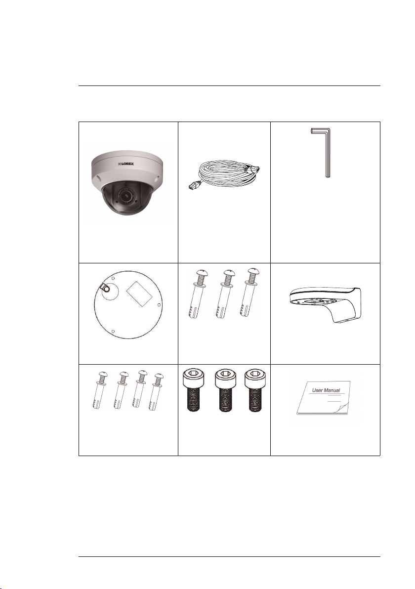
The system comes with the following components:
IP PTZ Dome Camera
Mounting Template
Mounting Screws ST4 (x4)
& Anchors S6 (x4)
(For wall mounting bracket)
100ft (30.5m) Cat5e UL
Compliant Ethernet Ex-
tension Cable
Mounting Screws (x3)
& Anchors (x3)
(For camera)
Hex Bolt M4x10 (x3)
(For wall mounting
bracket)
Allen Key (x2)
(One included in the mounting
hardware kit of the camera,
and one included in the
mounting
hardware kit of the wall mount-
ing bracket)
Wall Mounting Bracket
Installation Diagram Guide
and Instructional Manual
#LX400075; r.38010/38010; en-US
2

3
Connecting the Camera
It is recommended to connect the camera to your NVR and test the PTZ controls before permanent installation. For instructions on how to setup PTZ controls, see 5 Controlling the PTZ Camera with an NVR.
3.1 OPTION 1: Connecting Cameras to an NVR
1. Connect the PoE connector on the camera cable to the included Ethernet
extension cable.
2. Connect the Ethernet extension cable to one of the PoE ports on the back
panel of your NVR.
NOTE
You can use a single CAT5e Ethernet cable up to 300ft (91m) to connect the camera to
your NVR. Compatible with all Lorex HD NVRs, excluding the LNR200 & LNR300 Series. For the most up-to-date list of compatible recorders, please visit www.lorextechnology.
com/support
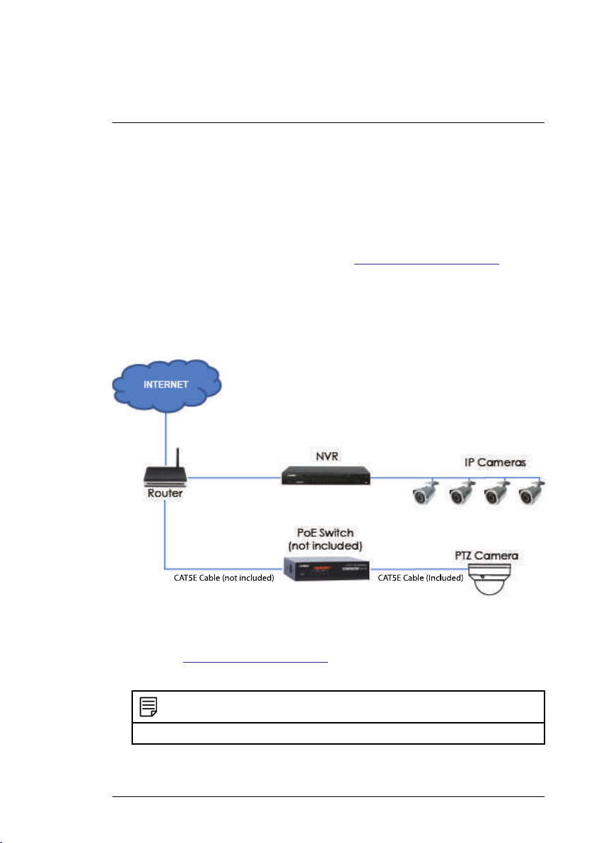
3.2 OPTION 2: Connecting Cameras to the Local Area Network (LAN)
For flexibility, you may also connect the camera to the same Local Area Network (LAN) as the NVR. This is accomplished by connecting the camera to
the same
router (not included) as the NVR. For these installations, an external
PoE switch (sold separately) or power adapter (not included) must be used to
provide power to the camera. You must also add the camera on the NVR before it will show a
picture on the monitor or be recorded by the NVR.
What is PoE?
PoE is a technology that allows Ethernet cables to carry electrical power to
connected devices. Compatible NVRs use integrated PoE ports to provide
#LX400075; r.38010/38010; en-US
3
3
Connecting the Camera
power and PTZ commands to the camera, as well as video connection to the
NVR over a single CAT5E cable. In order to use PoE with this IP camera, you
must connect it directly to a compatible NVR or a PoE switch on the same network as the NVR.
For the most up-to-date list of compatible recorders,
please visit www.lorextechnology.com/support
PoE switches are available for purchase on www.lorextechnology.com.
Complete the following steps to connect the camera to the NVR over the LAN.
Step 1 of 2 — OPTION A: Connecting the camera to your local network
using an
optional PoE switch:
1. Connect an Ethernet cable of up to 300ft (91m) rated CAT5e or higher
(not included) from the LAN port on an external PoE switch (sold separately on www.lorextechnology.com) to your router. Connect the power ca-
ble to the PoE switch and plug into a power outlet or surge protector.
NOTE
Terminology may vary depending on the model of PoE switch you have.
#LX400075; r.38010/38010; en-US
4
3
Connecting the Camera
2. Connect the camera to the PoE switch using the included Ethernet cable
(or a CAT5e Ethernet cable of up to 300ft (91m)). The PoE switch will provide power and video transmission the same way as your NVR.
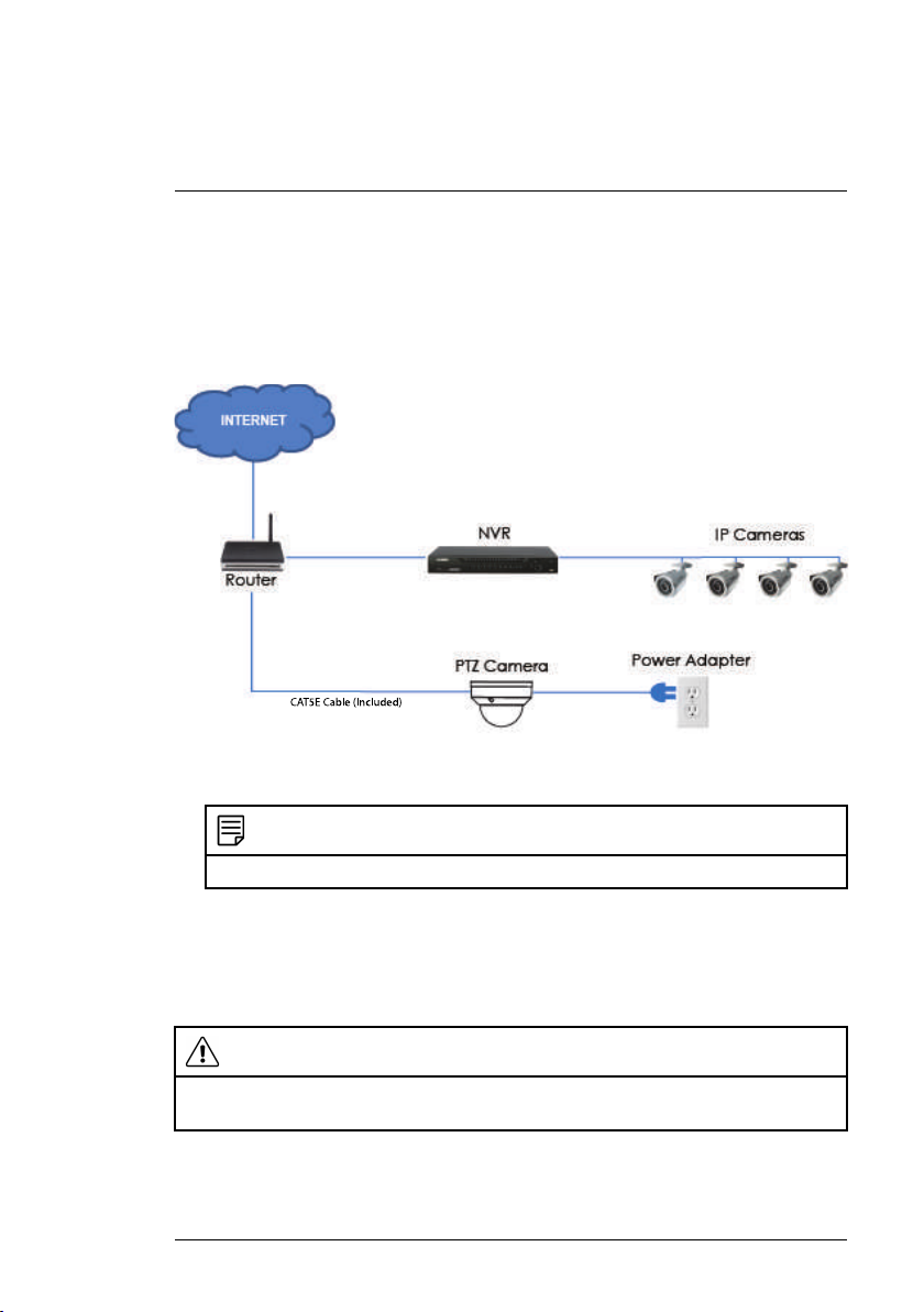
Step 1 of 2 — OPTION B: Connecting the camera to your local network
using a power adapter:
1. Connect the camera to a power adapter (not included).
NOTE
For power requirement specification, see 6 Technical Specifications.
2. Connect the camera to a router in the same network as your NVR using
the included Ethernet cable (or an Ethernet cable of up to 300ft (91m)
rated CAT5e or higher).
Step 2 of 2: Add the camera to your NVR:
CAUTION
The following instructions are based on the Lorex LNR400 Series NVR. See your NVR’s instruction manual for instructions on controlling the PTZ camera with your system.
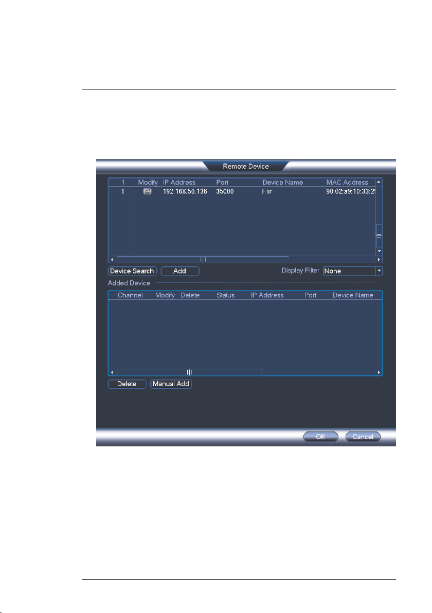
1. Right-click and select Device Search.
#LX400075; r.38010/38010; en-US
5
3
Connecting the Camera
2. Log in using the admin account (default User Name: admin; default Pass-
word: 000000).
3. Click Device Search. The system searches the network for compatible
cameras.
4. Check the camera(s) you would like to add.
#LX400075; r.38010/38010; en-US
6
3
Connecting the Camera
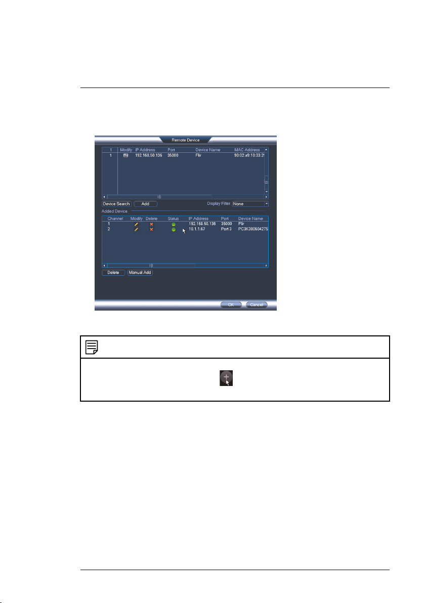
5. Click Add. The Status indicator turns green to show the camera is suc-
cessfully connected.
6. Click OK to save changes.
NOTE
You can also add a camera to a specific channel by hovering the mouse over an empty
channel in split-screen view and clicking
camera you would like to add. Right click to exit.
#LX400075; r.38010/38010; en-US
. Click Device Search and double-click the
7
4
Installation
4.1 Installation Tips and Warnings
• Camera is rated for outdoor use. It is recommended to install the camera in
a sheltered area, such as under the eaves on a roof.
• Use the included wall mounting bracket for wall installation.
Otherwise, the camera image will be sideways. You can also refer to the
included
installation diagram guide for wall mounting instructions.
• Camera is capable of seeing in low light conditions (0.1 Lux), but it cannot
see in total darkness.
NOTE
It is recommended to install the camera where there is some ambient light (for example, street lighting or starlight, moonlight, etc.) or leave some lighting on in the area
where the camera is installed.
• Mount the camera in a location that can support the camera weight.
• Mount the camera where the lens is away from direct and intense sunlight.
• Plan your cable wiring so that it does not interfere with power lines or telephone lines.
• Ensure you adhere to local building codes.
• Ensure that the camera wiring is not exposed or easily cut.
• Mount the camera in an area that is visible but out of reach.
NOTE
This camera is suitable for ceiling mounting. Wall mounting requires included wall mount.
4.2 Installation (Indoor/Outdoor)
The camera includes all necessary components for ceiling mounting and wall
mounting. For full instructions on each type of mounting, see 4.2.1 Wall
Mounting or 4.2.2 Ceiling Mounting.
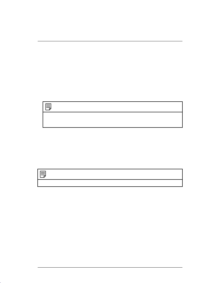
Before installing the camera, decide whether to run the cables through the
wall / ceiling (drilling required) or along the wall / ceiling. If you run the cables
along the wall / ceiling, you must run the cable through the cable notch on the
dome camera base. This will keep the dome camera base flush to the ceiling
when mounted.
#LX400075; r.38010/38010; en-US
8
4
Installation
4.2.1 Wall Mounting
CAUTION
Make sure to install in a location that can support the combined weight of the wall mounting bracket and the camera.
To wall mount the camera:
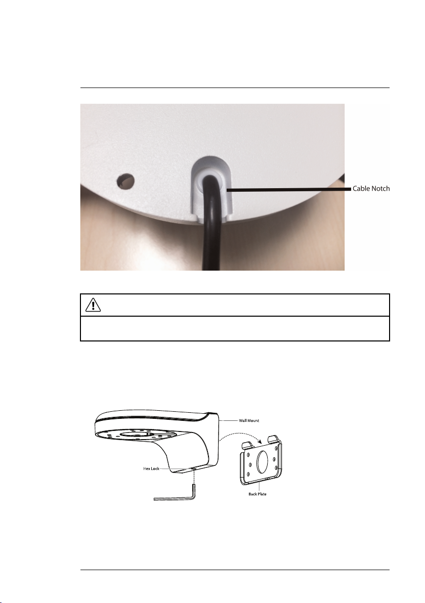
1. Use the Allen key (S3.0) included with the wall mounting bracket kit to
loosen the hex lock on the bottom of the wall mounting bracket. Once
loose, remove the back plate of the mounting bracket.
2. Use the Allen key included with the camera mounting kit to loosen the
dome camera cover screws (x3). Remove the dome camera cover.
#LX400075; r.38010/38010; en-US
9
4
Installation
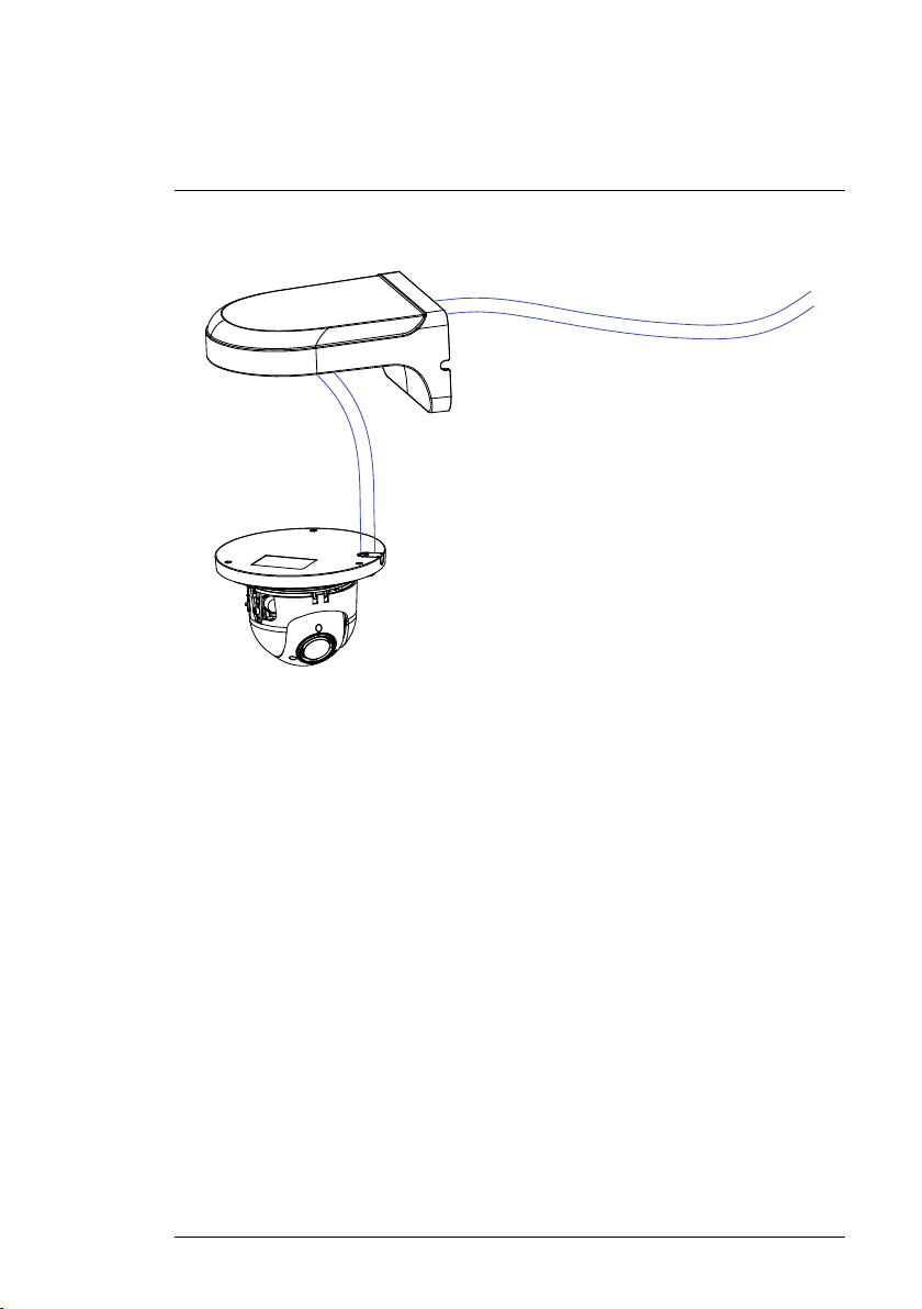
3. Insert the camera cable through the hole in the wall mounting bracket.
#LX400075; r.38010/38010; en-US
10
4
Installation
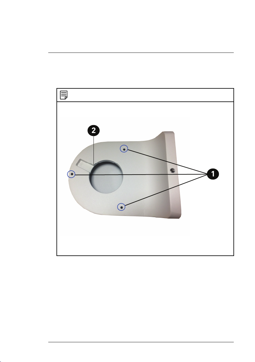
4. Align the 3 mounting holes on the dome camera base with the 3
corresponding
mounting holes on the wall mounting bracket.
NOTE
Ensure that the cable notch on the dome camera base is aligned with the cable notch
on the wall mounting bracket.
1: Mounting Holes
2: Cable Notch
5. Use the Hex Bolt M4x10 (x3) screws included with the wall mounting
bracket kit to
secure the position of the dome camera base.
#LX400075; r.38010/38010; en-US
11
4
Installation
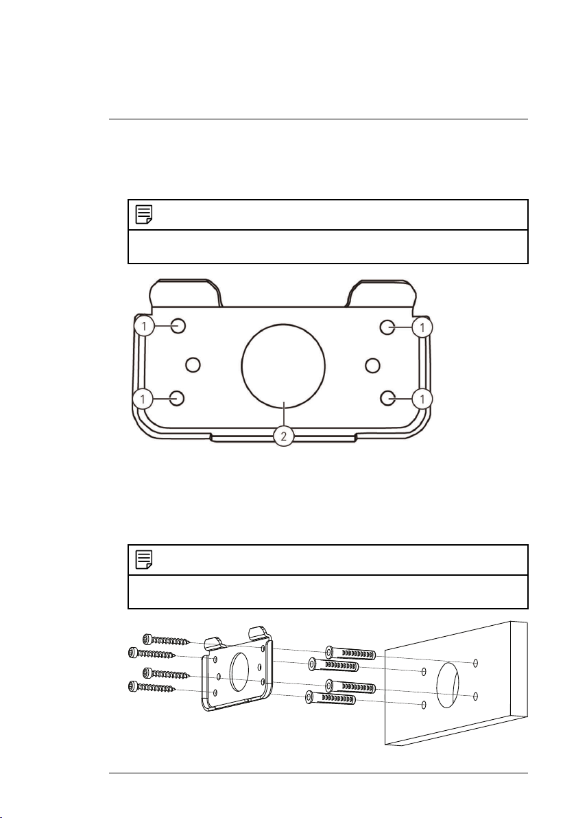
6. Holding the flat side of the back plate against the mounting surface, mark
holes for the mounting screws ST4 (x4) and the camera cable. Remove
the back plate and drill where marked.
NOTE
You do not need to mark holes for the camera cable if you plan to run it along the wall /
ceiling.
1: Mounting screw ST4 (x4) holes, 2: Camera cable hole
7. Attach the back plate to the mounting surface using the mounting screws
ST4 (x4)
included with the wall mounting bracket kit.
NOTE
Use the drywall anchors included with the wall mounting bracket kit if installing on a
drywall surface.
#LX400075; r.38010/38010; en-US
12
4
Installation
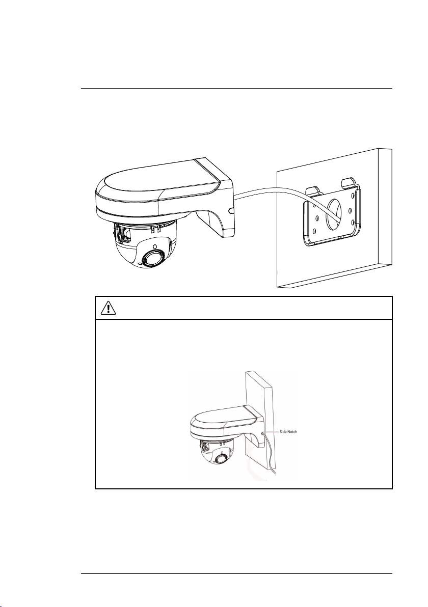
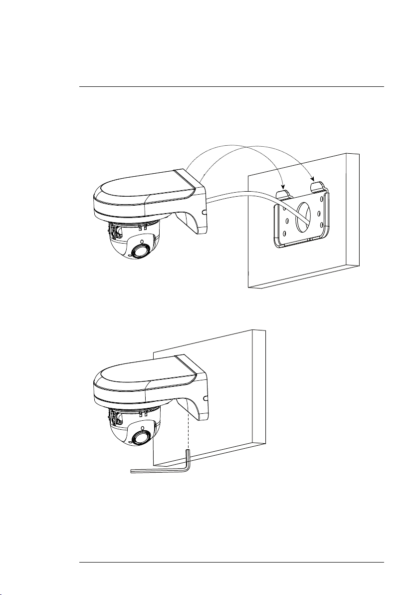
8. Connect the camera cable as shown in the 3 Connecting the Camera sec-
tion, then feed the cables through the cable hole in the back plate (attached to the mounting surface).
CAUTION
If you run the cables along the mounting surface, you must run the cable through
the side notch on the wall mounting bracket. The camera cable will hang alongside
the wall mounting bracket — see image below for reference:
#LX400075; r.38010/38010; en-US
13
4
Installation
9. Lower the wall mounting bracket onto the back plate. Ensure that the 2
metal flaps on the back plate lock into the 2 grooves in the wall mounting
plate.
10. Use the included Allen key (S3.0) to tighten the hex lock on the bottom of
the wall mounting bracket.
11. Replace the dome camera cover and tighten the dome camera cover
screws using the Allen key included with the camera mounting kit.
12. Remove the vinyl film from the dome cover once installation is complete.
#LX400075; r.38010/38010; en-US
14
4
Installation
4.2.2 Ceiling Mounting
To ceiling mount the camera:
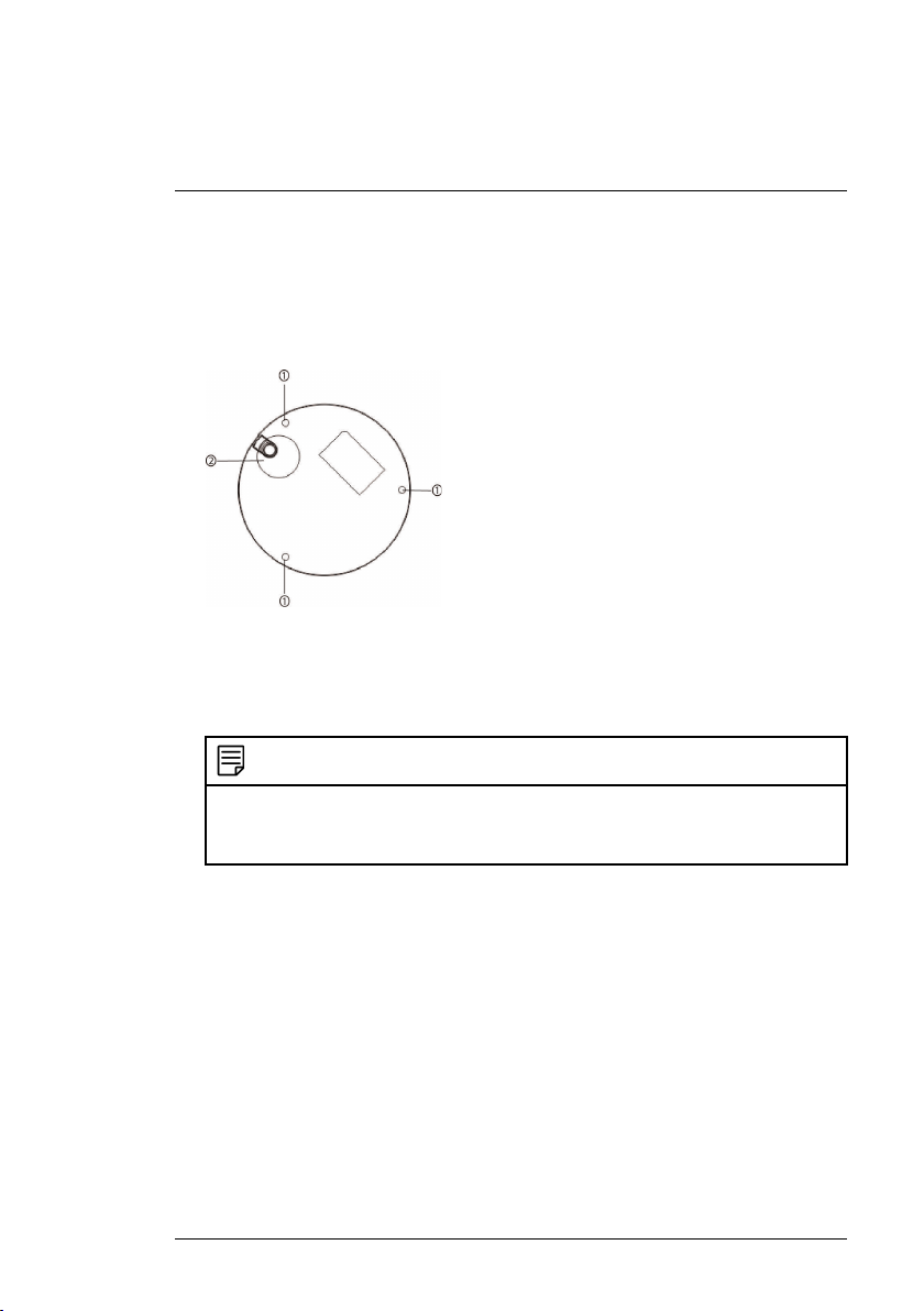
1. Use the mounting template included with the camera mounting kit to mark
holes for the mounting screws (x3) and camera cable.
1. Mounting screw holes; 2. Camera cable hole (Optional)
2. Drill holes for the mounting screws, drywall anchors (optional) and camera
cable (optional).
NOTE
• Use the included drywall anchors if installing on a drywall surface.
• If you are planning on running the cables along the mounting surface, there is no
need to drill a hole for the camera cable.
3. Use the Allen key included with the camera mounting kit to loosen the
dome camera cover screws (x3). Remove the dome camera cover.
4. Connect the camera cables as shown in 3 Connecting the Camera.
5. Mount the dome camera base to the mounting surface using the mounting
screws (x3) and drywall anchors (x3) (optional) included with the camera
mounting kit.
6. Replace the dome camera cover and tighten the dome camera cover
screws using the included Allen key.
7. Remove the vinyl film from the dome cover once installation is complete.
#LX400075; r.38010/38010; en-US
15
5
Controlling the PTZ Camera
with an NVR
The camera can accept PTZ commands directly through the Ethernet cable.
There is no need to run special wiring to control the movement of the PTZ
camera.
NOTE
• The following instructions are based on the Lorex LNR400 Series NVR. See your
NVR’s instruction manual for instructions on controlling the PTZ camera with your
system.
• For the latest list of compatible NVRs, please visit www.lorextechnology.com/support.
To connect a PTZ camera to the system:
1. Connect the camera to your NVR as detailed in 3 Connecting the Camera.
2. Right-click and click Main Menu. Enter the system user name (default:
admin) and password (default: 000000) if prompted.
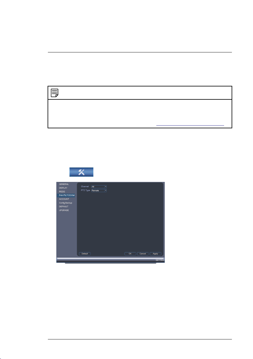
3. Click
4. Under Channel, select the channel your PTZ camera is connected to.
5. Under PTZ Type, select Remote.
6. Click OK. You can now control your PTZ camera using the system.
5.1 Controlling a PTZ Camera (Local NVR)
1. In Live View, double-click the channel that has the PTZ camera connected
to open in full-screen.
#LX400075; r.38010/38010; en-US
>SETTING>PAN/TILT/ZOOM.
16
5
Controlling the PTZ Camera with an NVR
2. Right-click and click PTZ. Enter the system user name and password if
prompted. The PTZ menu opens.
3. Use the on-screen controls to control the camera.
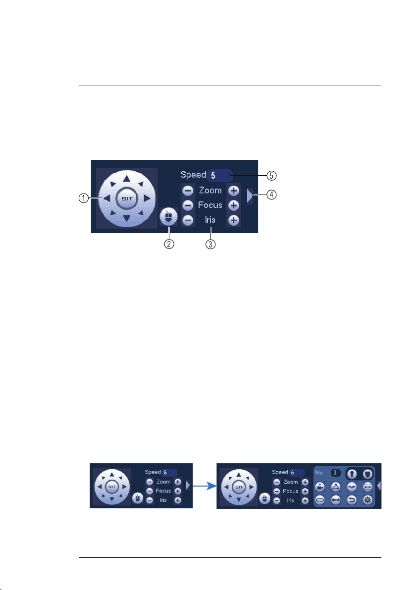
PTZ Controls
1. Direction keys: Click to pan and tilt the camera. Click SIT to stop the current action.
2. PTZ Trace: Click to activate mouse PTZ Trace mode. You can do the
following:
• Click and drag to move the camera.
• Use the scroll wheel to zoom in and out.
• Right-click to exit and return to normal PTZ controls.
3. Zoom/Focus/Iris: Click +/- to adjust the zoom, focus, and iris.
4. Advanced controls: Click to open advanced PTZ controls.
5. Speed: Enter a PTZ speed between 1 (slowest) and 8 (fastest).
5.2 Advanced PTZ Controls
Advanced PTZ controls can be used to save camera positions and cycle
through various positions, and automate camera actions.
To open advanced PTZ controls:
• Click the arrow in the PTZ control window to open advanced controls.
#LX400075; r.38010/38010; en-US
17
5
Controlling the PTZ Camera with an NVR
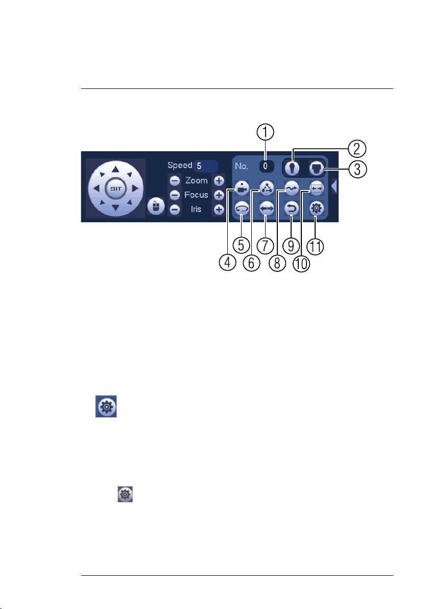
Advanced PTZ controls overview:
1. No.: Select the number of the action you want to perform.
2. Not supported.
3. Not supported.
4. Preset: Click to call the selected preset.
5. Not supported.
6. Tour: Click to run the selected tour.
7. Not supported.
8. Pattern: Click to run the selected pattern.
9. Not supported.
10. Not supported.
11.
: Click to open the PAN/TILT/ZOOM menu, where you can set up
Presets, Tours, and Patterns.
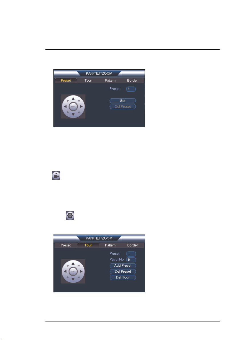
5.2.1 Presets
Presets will save a camera position for quick retrieval.
To add presets:
1. Click
#LX400075; r.38010/38010; en-US
to open the PAN/TILT/ZOOM menu.
18
5
Controlling the PTZ Camera with an NVR
2. Click the Preset tab.
3. Enter the number of the preset you want to create under Preset.
4. Move the camera to the desired position and click Set.
5. Right-click to return to the advanced PTZ controls window.
To go to a preset:
• Under No., select the number of the preset you would like to go to and click
.
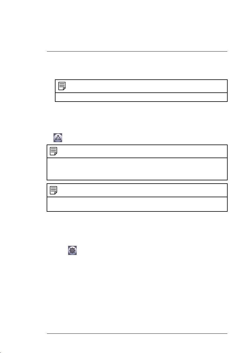
5.2.2 Tours
Tours will cycle through a set of presets.
To create a tour:
1. Click
to open the PAN/TILT/ZOOM menu.
2. Click the Tour tab.
3. Under Patrol No., select the tour you would like to configure.
4. Under Preset, select a preset you would like to add to the tour.
#LX400075; r.38010/38010; en-US
19
5
Controlling the PTZ Camera with an NVR
5. Click Add Preset.
6. Repeat steps 4 and 5 to add additional presets to the tour.
NOTE
Click Del Tour to clear all presets from a tour.
7. Right-click to return to the advanced PTZ controls window.
To run a tour:
• Under No., select the number of the tour you would like to go to and click
.
NOTE
• There is a 5 second minimum pause between presets.
• Tour panning / tilting speed is slower than manual panning / tilting speed. The reduced
speed maximizes reliability.
NOTE
The camera's full panning range is 355°. However, we recommend you do not make the
camera pan more than 270° between any two points in a tour.
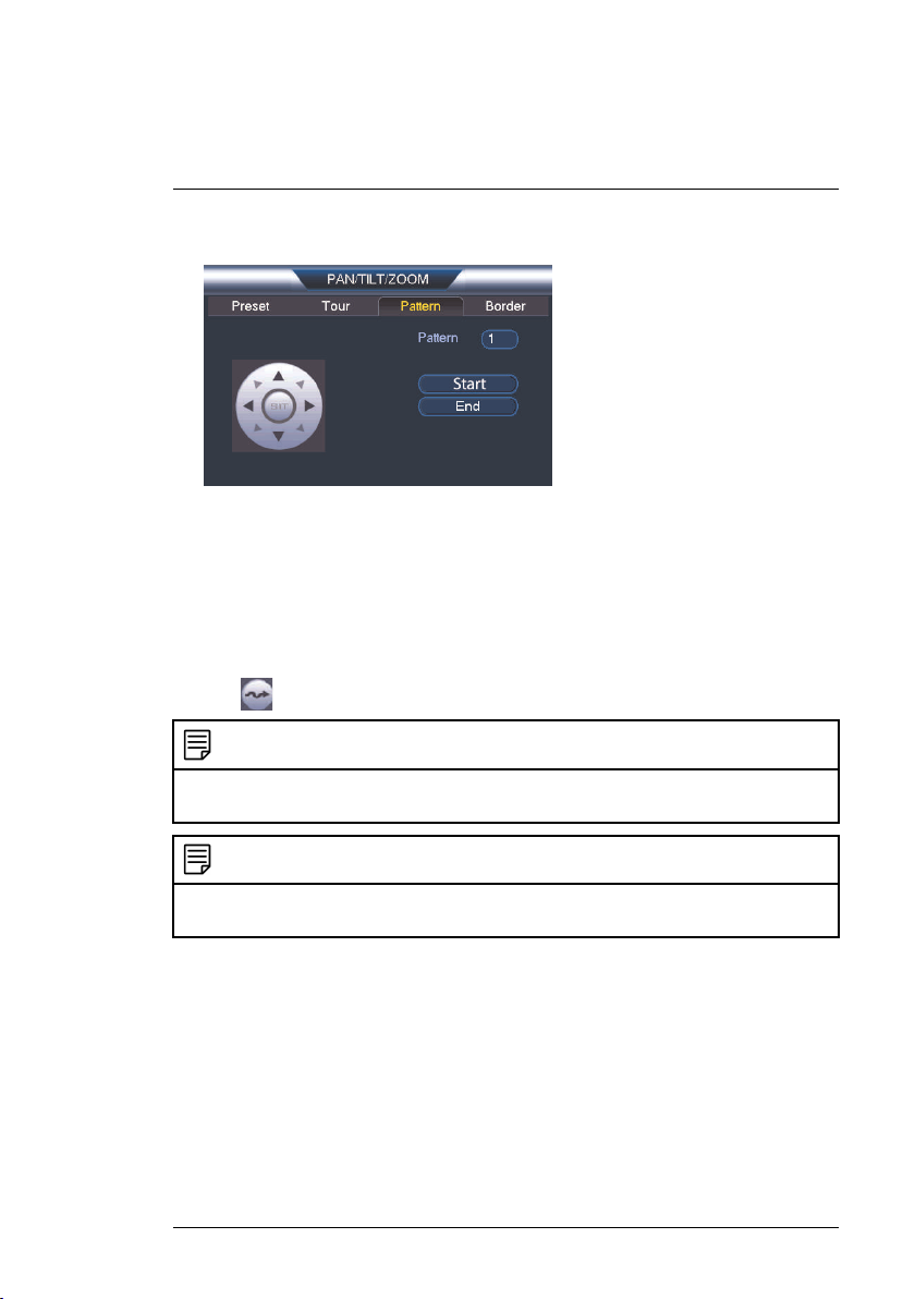
5.2.3 Pattern
Patterns automatically cycle the camera between two positions.
To create a pattern:
1. Click
#LX400075; r.38010/38010; en-US
to open the PAN/TILT/ZOOM menu.
20
5
Controlling the PTZ Camera with an NVR
2. Click the Pattern tab.
3. Under Pattern, enter the pattern you would like to configure.
4. Move the camera into the desired start position and click Start.
5. Move the camera into the desired end position and click End.
6. Right-click to return to the advanced PTZ controls window.
To run a pattern:
• Under No., select the number of the pattern you would like to go to and
click
The camera's full panning range is 355°. However, we recommend you do not make the
camera pan more than 270° between any two points in a pattern.
For instructions on how to control the PTZ camera using the smartphone or tablet app, refer to your DVR's instructional manual.
#LX400075; r.38010/38010; en-US
.
NOTE
NOTE
21
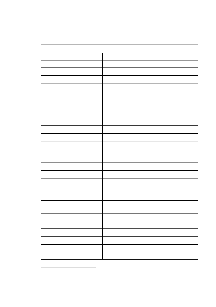
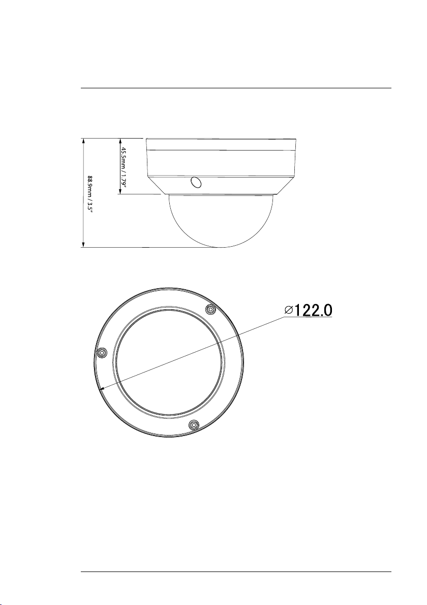
6
Technical Specifications
Image Sensor 1/2.7", CMOS 2.1 MP
Video Format
Effective Pixels 1928 (H) x 1088 (V)
Resolution Up to 1080p
Range 0°~355° Pan; 0°~90° Tilt
Pan/Tilt Speed Manual Speed — Max 80°/Sec Pan; Max 40°/Sec Tilt
Zoom 4x Optical Zoom & 16x Digital Zoom
Scan System
Synchronization
S / N Ratio
Iris Auto Iris
Min. Illumination
Lens / Lens Type 2.7mm ~ 11mm ,F1.6 ~ F2.7 / Auto / Manual Focus
Field of View (Horizontal) 95°~30°
Day/Night IR Cut Filter (ICR)
Termination RJ45 10 M / 100M Ethernet
Video Output RJ45
Power Requirement PoE (Power over Ethernet, Class 2); 12V DC
Power Consumption Max. 500mA
Operating Temperature Range -22°F ~ 140°F / -30°C ~ 60°C
Operating Humidity Range
Indoor/Outdoor Both (IP66)
Weight (Camera Alone)
Weight (Camera & Wall Mount)
NTSC / PAL
Preset Speed — Max 100°/Sec Pan; Max 60°/Sec
Tilt
Tour Speed — Max 80°/sec Pan; Max 40°/Sec Tilt
Progressive
Internal
≥50dB
0.1 Lux in Color; 0.05 Lux in Black and White
(Optional)
<95%RH
1
1.20lbs / 0.54kg
2.35lbs / 1.06kg
1. Not intended for submersion in water. Installation in a sheltered location recommended.
#LX400075; r.38010/38010; en-US
22
6
Technical Specifications
6.1 Dimensions
Camera Alone:
#LX400075; r.38010/38010; en-US
23
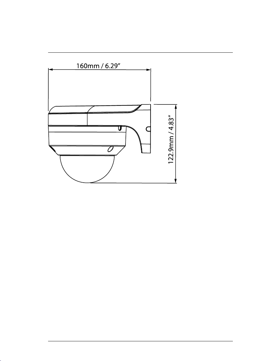
6
Technical Specifications
Camera and Wall Mount:
#LX400075; r.38010/38010; en-US
24

7
Troubleshooting
There is no picture at night.
• Camera is capable of seeing in extremely low light conditions (0.1 Lux), but
it cannot see in total darkness. It is recommended to install the camera
where there is some
ambient light (e.g. street lighting, starlight, moonlight, etc.) or leave a light
on in the area where the camera is installed.
No image at startup.
• The camera may take up to 1 minute to power up after being connected to
the NVR. Wait 2 minutes before following steps below.
• Check to ensure your camera is properly connected (see 3 Connecting the
Camera).
• Ensure the camera is connected to a router on the same network as the
NVR.
• If the camera is connected to the LAN, you must search your network for
cameras using the NVR. See your NVR’s instruction manual for details.
• Make sure that the cable run is within the limitations specified in 3 Connect-
ing the Camera. All Ethernet cables must be rated CAT5e or higher.
• If using the power adapter (not included), connect the power adapter to a
different outlet.
• Ethernet cable may be damaged or not connected properly. Check your cable run or try a different cable.
• Reset the camera to factory default settings. See 8 Resetting the Camera
for details.
No image or camera image is unclear.
• Dome cover is dirty. Clean the dome cover with a soft, slightly damp cloth.
Do not use anything other than water to clean the dome cover, as chemicals such as acetone can permanently damage the plastic.
Image is distorted.
• Digital zoom is activated. Activating digital zoom may reduce the resolution
of the camera image. Zoom out completely to return to the camera’s optimal resolution. See 5.1 Controlling a PTZ Camera (Local NVR) for instructions on using the zoom controls.
• Image may become unclear when camera is tilted too close to the camera
base (e.g. pointed parallel to the ceiling). Tilt the camera using NVR or
FLIR Cloud™ Client PTZ controls.
#LX400075; r.38010/38010; en-US
25

7
Troubleshooting
Image is too bright.
• Ensure your camera isn’t pointed directly at a source of light (e.g. sun or
spot light).
• Check your NVR’s brightness and contrast settings.
• Move your camera to a different location.
Image is too dark.
• Check your NVR’s brightness and contrast settings.
• Move your camera to a different location.
NVR motion detection is constantly triggering.
• Turn off motion detection on the channel the PTZ camera is connected to.
NVRs use video motion detection, which means they detect motion by
looking for changes between frames (images) in the video. If the camera is
moving, the NVR will detect this as motion.
#LX400075; r.38010/38010; en-US
26

8
Resetting the Camera
The camera features a hard reset button that is used to reset all camera settings back to their default values. This is useful in case you want to revert camera image settings back to their default values.
To reset the camera to default settings:
1. Connect the camera as detailed in 3 Connecting the Camera. Make sure
the camera is powered on.
2. Use the Allen key included with the camera mounting kit to loosen the
dome camera cover screws (x3). Remove the dome camera cover.
#LX400075; r.38010/38010; en-US
27
 Loading...