

Lorex LNZ32P12 series Instruction Manual
Instruction
Manual
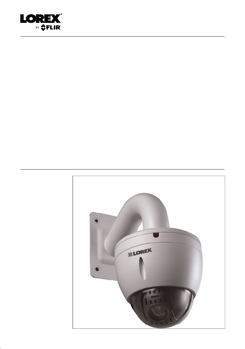
LNZ32P12 12x
Network PTZ
Camera Series
Thank you for purchasing this product. Lorex Corporation is committed to providing our
customers with a high quality, reliable security solution.
This manual refers to the following models:
LNZ32P12
LNZ32P12S
For the latest online manual, downloads and product updates, and to learn about our
complete line of accessory products, please visit our website at:
www.lorextechnology.com
WARNING
RISK OF ELECTRIC SHOCK
DO NOT OPEN
WARNING: TO REDUCE THE RISKOF ELECTRIC SHOCK DO NOT
REMOVE COVER. NO USER SERVICEABLE PARTS INSIDE.
REFER SERVICING TO QUALIFIED SERVICE PERSONNEL.
The lightning flash with arrowhead symbol, within an
equilateral triangle, is intended to alert the user to the
presence of uninsulated "dangerous voltage" within the
product’s enclosure that may be of sufficient magnitude to
constitute a risk of electric shock.
The exclamation point within an equilateral triangle is
intended to alert the user to the presence of important
operating and maintenance (servicing) instructions in the
literature accompanying the appliance.
WARNING: TO PREVENT FIRE OR SHOCK HAZARD, DO NOT EXPOSE
THIS UNIT TO RAIN OR MOISTURE.
CAUTION: TO PREVENT ELECTRIC SHOCK, MATCH WIDE BLADE OF
THE PLUG TO THE WIDE SLOTAND FULLY INSERT.
#LX400020; r.41770/42005; en-US
iii

Table of contents
1 Safety Instructions ..............................................................1
2 Getting Started ................................................................... 2
3 Connecting the Camera .......................................................3
3.1 Option 1: Connecting the Camera to an NVR ....................3
3.2 Connecting Cameras to the Local Area Network
3.3 Adding the PTZ Camera to the LNR / NR Series
3.4 Adding the PTZ camera to the LNK Series NVRs...............8
4 Installation ......................................................................... 9
4.1 Installation Tips and Warnings.......................................9
4.2 Installation (Indoor/Outdoor).......................................... 9
5 Controlling the PTZ Camera with an NVR.............................. 15
6 Controlling the PTZ camera with LNR / NR Series
NVRs ............................................................................... 16
6.1 Controlling the PTZ Camera........................................ 16
6.2 Advanced PTZ Controls ............................................. 17
7 Controlling the PTZ camera with LNK Series NVRs................ 22
7.1 Controlling the PTZ camera ........................................ 22
8 Technical Specifications .................................................... 26
8.1 Dimensions ............................................................. 27
9 Troubleshooting ................................................................ 28
10 Resetting the Camera ........................................................ 30
(LAN).......................................................................3
NVRs.......................................................................6
6.2.1 Presets........................................................ 18
6.2.2 Tours........................................................... 19
6.2.3 Pattern......................................................... 20
6.2.4 Auto Scan .................................................... 21
7.1.1 Setting PTZ Presets ....................................... 24
#LX400020; r.41770/42005; en-US
iv

1
Safety Instructions
• Read this guide carefully and keep it for future reference.
• Follow all instructions for safe use of the product and handle with care.
• Use the camera within given temperature, humidity, and voltage levels
noted in the Technical Specifications.
• Camera is rated for outdoor use and is weatherproof when properly installed. Camera is not intended for submersion in water. Installation under
a sheltered environment is recommended.
• Do not disassemble the camera.
• Do not point the camera directly towards the sun or a source of intense
light.
• Use only the supplied regulated power supply. Use of a non-regulated,
non-conforming power supply can damage this product and voids the
warranty.
• Make sure to install the camera in a location that can support the camera
weight. If mounting the camera on a drywall surface, you must drill at least
2 of the mounting screws through a wooden stud. See 4.2 Installation (In-
door/Outdoor), page 9 for complete installation instructions.
• Make sure there are no live electrical cables in the area where you plan to
mount the camera.
• Periodic cleaning may be required. Use a damp cloth only. Do not use anything other than water to clean the dome cover, as chemicals such as acetone can permanently damage the plastic.
#LX400020; r.41770/42005; en-US
1
2
Getting Started
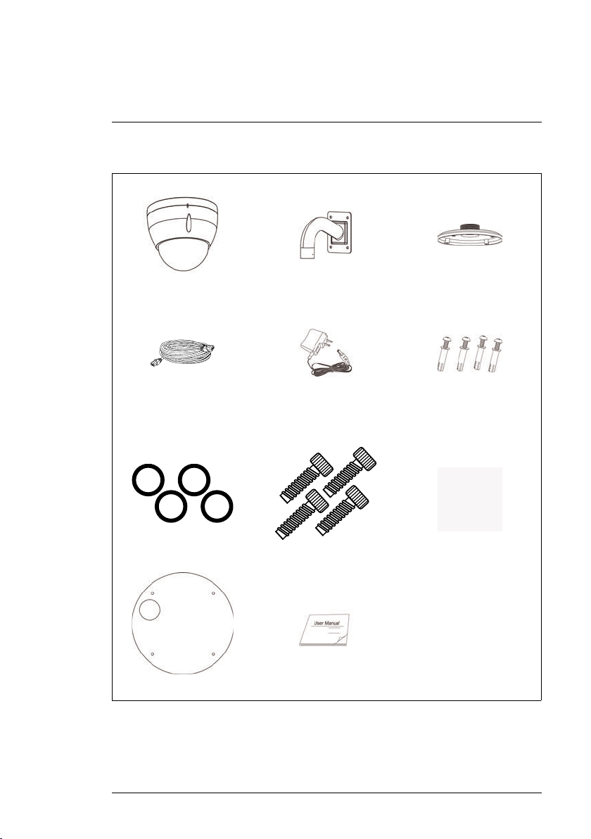
The system comes with the following components:
PTZ Camera Wall Mount
100ft (30.5m) CAT5e UL
Compliant Ethernet Exten-
sion Cable
4x O-Rings
Mounting Template
Power Adapter
4x Allen Bolts
Instruction Manual
Pendant Cap
Mounting Screws
& Anchors
Allen Key
#LX400020; r.41770/42005; en-US
2
3
Connecting the Camera
NOTE
It is recommended to connect the camera to your NVR and test the PTZ controls before
permanent installation. For instructions on how to set up PTZ controls, see 5 Controlling
the PTZ Camera with an NVR, page 15.
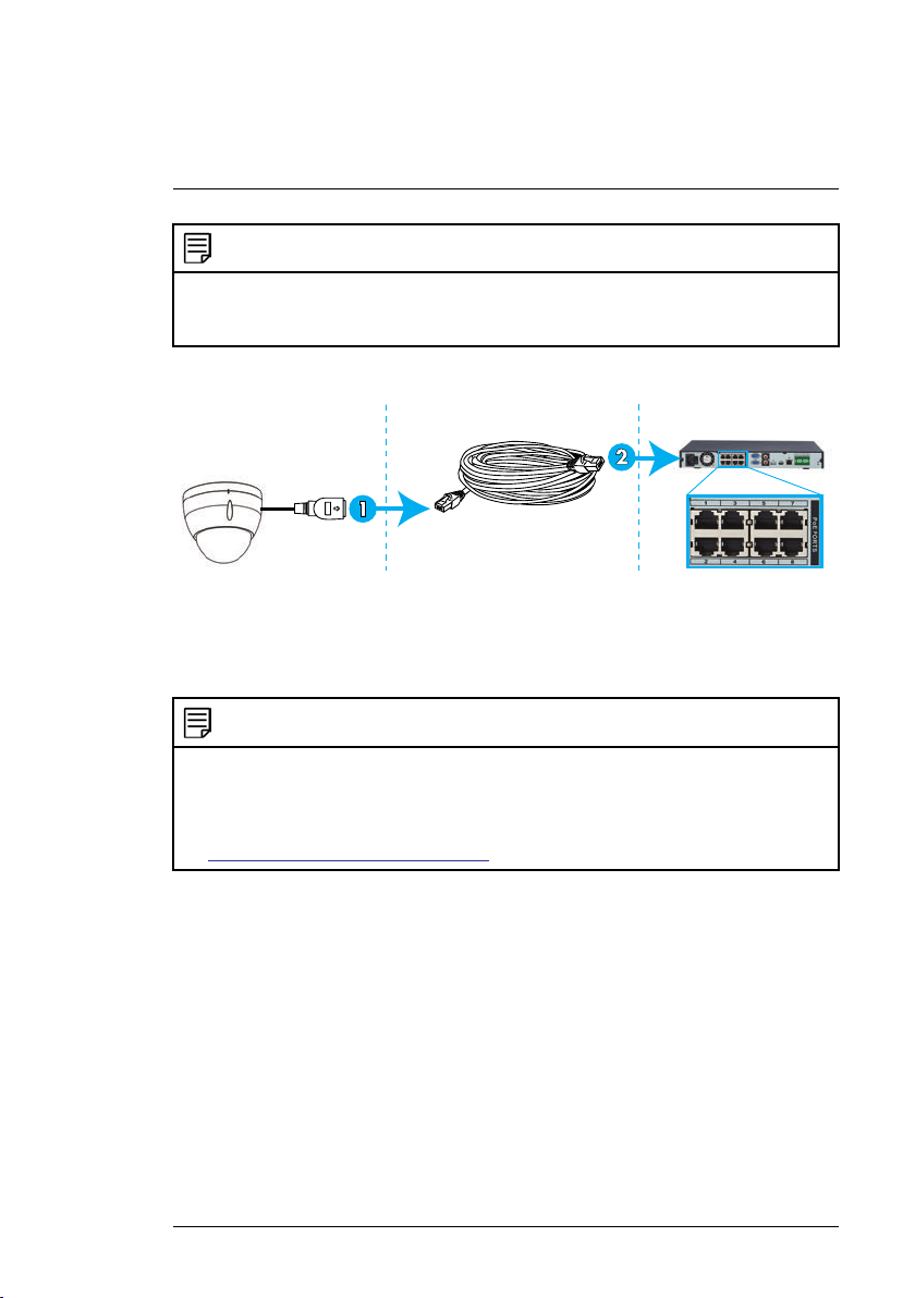
3.1 Option 1: Connecting the Camera to an NVR
1. Connect the PoE+ connector on the camera cable to the included Ether-
net extension cable.
2. Connect the Ethernet extension cable to one of the PoE+ ports on the
back panel of your NVR.
NOTE
• You can use up to a 300ft (91m) CAT5e Ethernet cable to connect the camera to your
NVR.
• The camera is compatible with all Lorex HD NVRs except for LNR200 & LNR300 Series. For the most up-to-date list of compatible recorders, please visit
www.lorextechnology.com/compatibility.
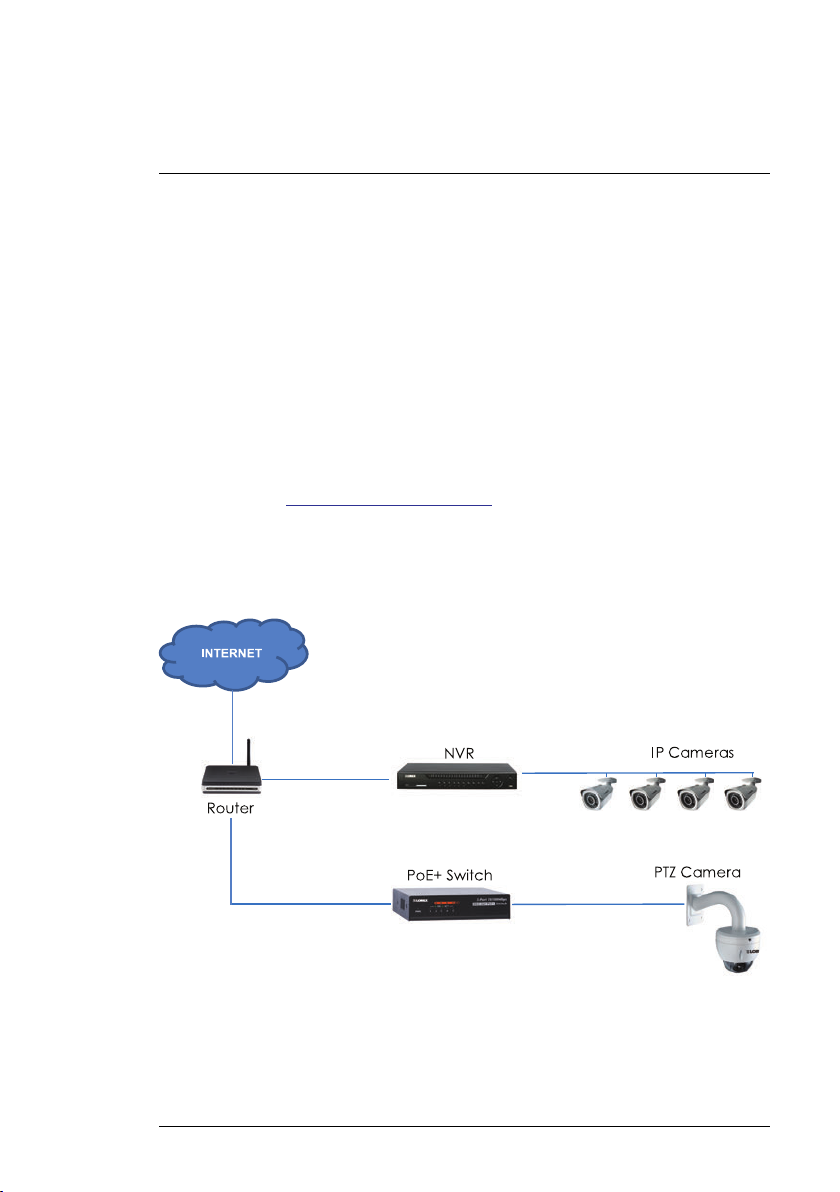
3.2 Connecting Cameras to the Local Area Network (LAN)
For flexibility, you may also connect the camera to the same Local Area Network (LAN) as the NVR. This is accomplished by connecting the camera to
the same router as the NVR. For these installations, an external PoE+ switch
(sold separately) or power adapter (included) must be used to provide power
to the camera. You also must add the camera on the NVR before it will show a
picture on the monitor or be recorded by the NVR.
#LX400020; r.41770/42005; en-US
3
3
Connecting the Camera
What is PoE+?
PoE (Power over Ethernet) is a technology that allows Ethernet cables to carry
electrical power to connected devices. High-powered devices such as PTZ
cameras use PoE+ (also known as PoE class 4 or IEEE 802.3at), which provides more power to connected devices than standard PoE. Compatible
NVRs use integrated PoE+ ports to provide power and PTZ commands to the
camera, as well as video connection to the NVR. PoE+ ports will provide up to
30W to each connected device, whereas standard PoE (class 3) ports only
provide up to 15W. In order to use this PoE+ rated camera without the included power adapter, you must connect it directly to a compatible NVR (compatible with all Lorex HD NVRs except for LNR200 & LNR300 Series) or a
PoE+ switch on the same network as the NVR. PoE+ switches are available
for purchase on www.lorextechnology.com (model #: ACCLPS241B).
Complete the following steps to connect the camera to the NVR over the LAN.
Step 1 of 2 — Option A: Connecting the camera to your local network
using an optional PoE+ switch:
#LX400020; r.41770/42005; en-US
4
3
Connecting the Camera
1. Connect an Ethernet cable of up to 300ft (91m) rated CAT5e or higher
(not included) from the LAN port on an external PoE+ switch (sold separately on www.lorextechnology.com) to your router. Connect the power ca-
ble to the PoE+ switch and to a power outlet or surge protector.
NOTE
Terminology may vary depending on the model of PoE+ switch you have.
2. Connect the camera to the PoE+ switch using the included Ethernet cable
(or a CAT5e Ethernet cable of up to 300ft (91m)). The PoE+ switch will
provide power and video transmission the same way as your NVR.
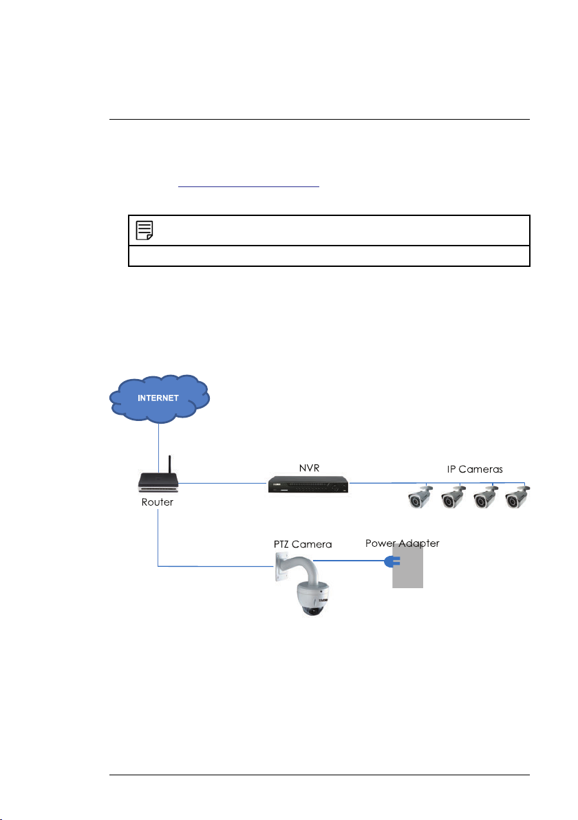
Step 1 of 2 — Option B: Connecting the camera to your local network
using power adapters:
1. Connect the camera to the included power adapter.
2. Connect the camera to a router in the same network as your NVR using
the included Ethernet cable (or an Ethernet cable of up to 300ft (91m)
rated CAT5e or higher).
#LX400020; r.41770/42005; en-US
5
3
Connecting the Camera
Step 2 of 2: Add the camera to your NVR:
• For instructions on adding the PTZ camera to the LNR / NR Series NVRs ,
see 3.3 Adding the PTZ Camera to the LNR / NR Series NVRs, page 6
• For instructions on adding the PTZ camera to the LNK Series NVRs, see
3.4 Adding the PTZ camera to the LNK Series NVRs, page 8
NOTE
For instructions on how to locate the serial and model number of your recorder, visit
www.lorextechnology.com and search for “Where is the Serial and Model Number located”.
3.3 Adding the PTZ Camera to the LNR / NR Series NVRs
To add the PTZ camera to the LNR / NR Series NVRs:
The following instructions are based on the LNR400 Series NVR. See your
NVR’s instruction manual for instructions on controlling the PTZ camera with
your system.
NOTE
• Not compatible with LNR200 / LNR300 Series NVRs. For the latest list of compatible
recorders, see www.lorextechnology.com/compatibility.
• You must have at least one empty channel before attempting to add the camera to the
NVR.
1. Right-click during live view and select Device Search .
2. Log in using the admin account (default User Name: admin; default Password: 000000).
#LX400020; r.41770/42005; en-US
6
3
Connecting the Camera
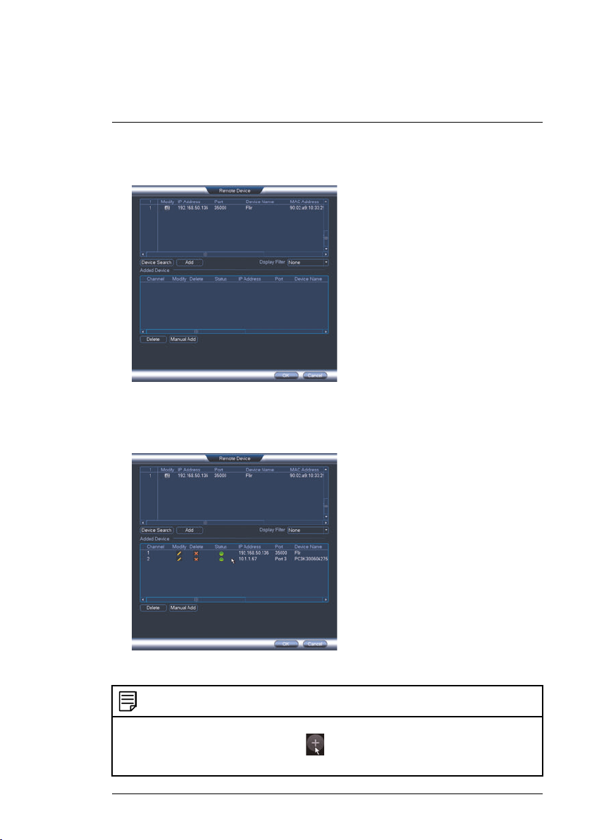
3. Click Device Search. The system searches the network for compatible
cameras.
4. Check the camera(s) you would like to add.
5. Click Add. The Status indicator turns green to show the camera is successfully connected.
6. Click OK to save changes.
NOTE
You can also add a camera to a specific channel by hovering the mouse over an empty
channel in split-screen view and clicking
camera you would like to add. Right click to exit.
#LX400020; r.41770/42005; en-US
. Click Device Search and double-click the
7
3
Connecting the Camera
3.4 Adding the PTZ camera to the LNK Series NVRs
To add the PTZ camera to the LNK Series NVRs:
The following instructions are based on the LNK7000 Series NVR. See your
NVR’s instruction manual for instructions on controlling the PTZ camera with
your system.
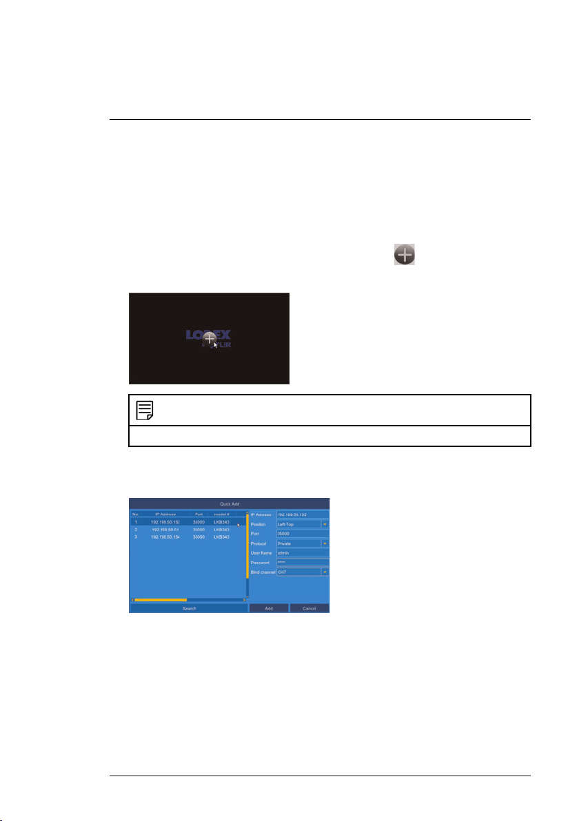
1. From live view, hover over a blank channel. Click
in the center of the
channel to add the PTZ camera from the LAN. A Quick Add menu opens.
NOTE
If prompted, enter the system user name (default: admin) and your password.
2. Click Search. The NVR scans the network for compatible cameras. A list
of compatible cameras appear on the left-side of the screen
3. Click the camera you would like to add. The selected camera’s attributes
appear on the right-side of the screen.
4. Under Protocol, select ONVIF.
5. Click Add.
#LX400020; r.41770/42005; en-US
8
4
Installation
4.1 Installation Tips and Warnings
WARNING
Make sure to install the camera in a location that can support the camera weight. If mount-
ing the camera on a drywall surface, you must drill the mounting screws through a wooden
stud. See 4.2 Installation (Indoor/Outdoor), page 9 for full installation instructions.
• Camera is rated for outdoor use. It is recommended to install the camera in
a sheltered area, such as under the eaves on a roof.
• It is recommended to install the camera as high up as possible to get the
best possible image.
• Camera is capable of seeing in low light conditions (0.05 Lux), but it cannot
see in total darkness. It is recommended to install the camera where there
is some ambient light (e.g. street lighting or starlight, moonlight, etc.) or
leave some lighting on in the area where the camera is installed.
• Mount the camera where the lens is away from direct and intense sunlight.
• Plan your cable wiring so that it does not interfere with power lines or tele-
phone lines.
• Ensure you adhere to local building codes.
• Ensure that the camera wiring is not exposed or easily cut.
• Mount the camera in an area that is visible but out of reach.
NOTE
This camera is suitable for wall and ceiling mounting.
4.2 Installation (Indoor/Outdoor)
To install the camera on a wall:
CAUTION
Make sure to disconnect power before installing the camera. Camera will begin moving immediately when power is connected.
1. Mark holes for the mounting screws (x4) and cables through the wall
mount bracket. Drill where marked.
2. Pull the Ethernet cable from your NVR, PoE+ switch or router through the
hole in the mounting surface.
#LX400020; r.41770/42005; en-US
9
4
Installation
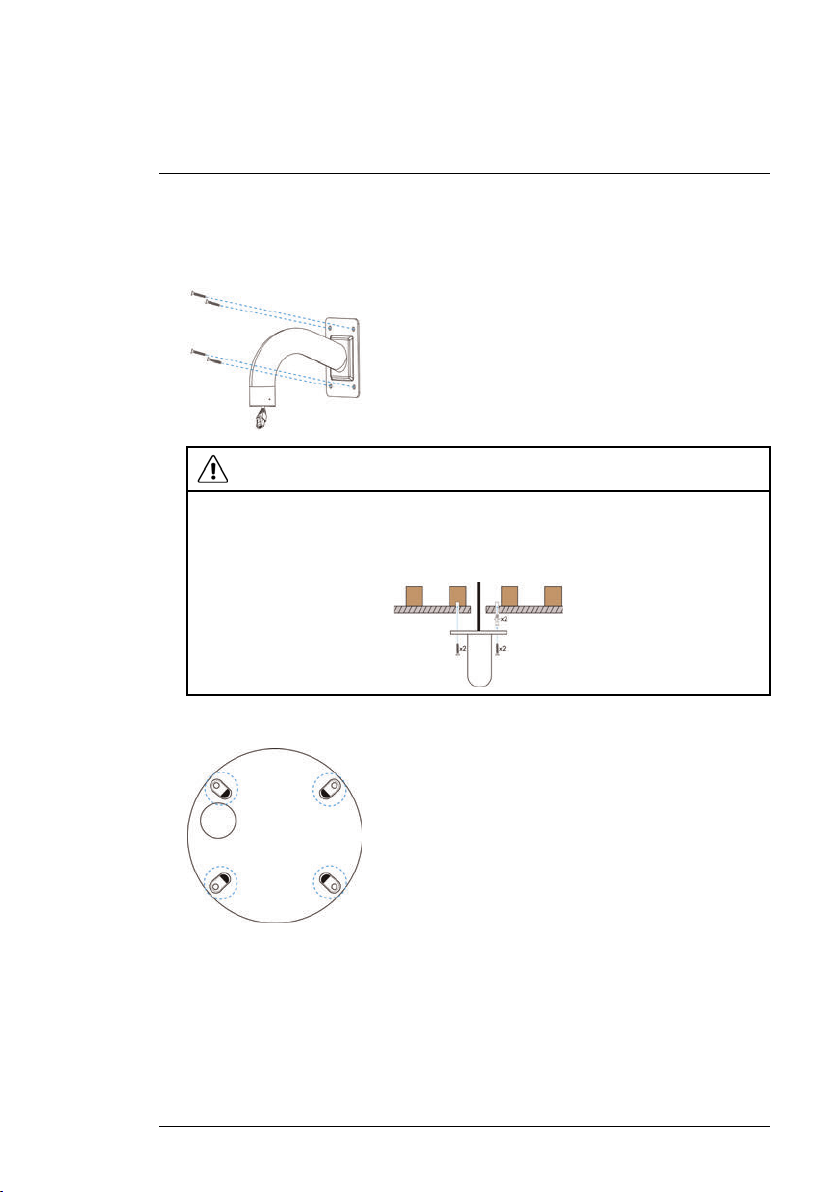
3. Pull the Ethernet cable through the wall mount bracket. Firmly attach the
wall mount bracket to the wall using the included mounting screws (x4)
and the included anchors (x4) if needed.
WARNING
Make sure to install the wall mount bracket in a location that can support the camera’s
weight. If mounting the camera on a drywall surface, you must drill at least 2 of the
mounting screws through a wooden stud to ensure a stable mount. See the diagram
below for details.
4. Remove plastic film from the screw holes on the bottom of the camera.
#LX400020; r.41770/42005; en-US
10
4
Installation
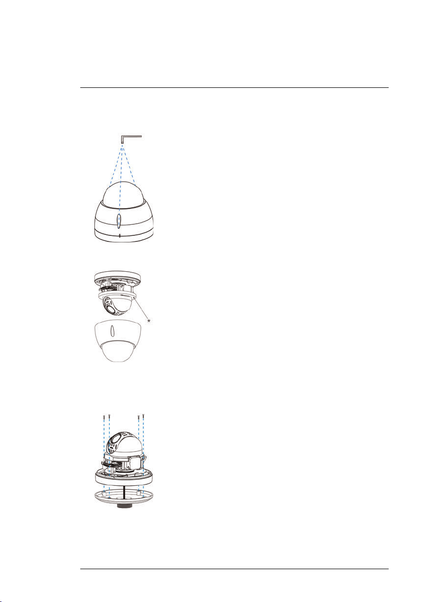
5. Use the included Allen key to loosen the dome cover screws (x3). Remove
the dome cover.
6. Remove the foam ring* around the camera module.
7. Pull the camera cables through the hole in the pendant cap. Use the included Allen bolts (x4) to attach the PTZ camera base firmly to the pendant cap. Tighten using the included Allen key.
#LX400020; r.41770/42005; en-US
11
4
Installation
8. Re-attach the dome cover, ensuring that the rubber O-ring around the
camera base is in place and the alignment arrow* on the dome cover lines
up with the camera base.
9. Tighten the dome cover screws (x3) using the included Allen key.
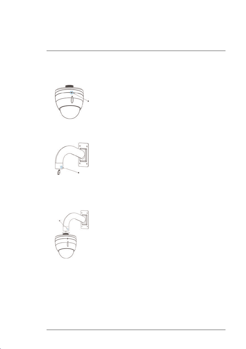
10. Loosen the security screw* on the wall mount bracket.
11. Connect the camera to the cabling in the wall mount bracket. See 3 Con-
necting the Camera, page 3 for full connection instructions.
12. Twist the pendant cap onto the wall mount bracket. Tighten the security
screw* on the wall mount bracket.
13. Remove protective vinyl sheet from the dome cover once installation is
completed.
#LX400020; r.41770/42005; en-US
12
4
Installation
To install the camera on a ceiling:
CAUTION
• Make sure to disconnect power before installing the camera. Camera will begin moving
immediately when power is connected.
• Make sure to install the camera in a location that can support the camera weight.
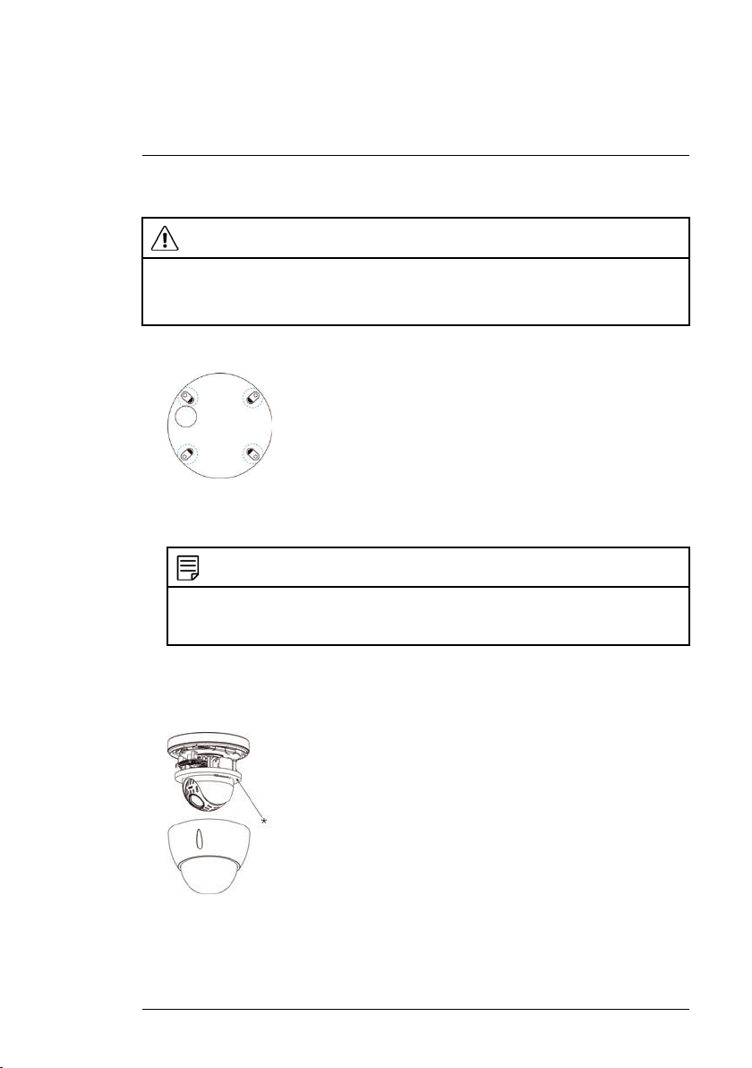
1. Remove plastic film from the screw holes on the bottom of the camera.
2. Use the included mounting template to mark holes for the mounting
screws and cables if needed. Drill where marked.
NOTE
If you run the cables along the mounting surface, you must run the cable through the
cable notch on the base of the camera. This will keep the camera base flush to the
surface when mounted.
3. Use the included Allen key to loosen the dome cover screws (x3). Remove
the dome cover.
4. Remove the foam ring* around the camera module.
5. Connect the camera to the cabling in the ceiling. See 3 Connecting the
Camera, page 3 for full connection instructions.
#LX400020; r.41770/42005; en-US
13
4
Installation
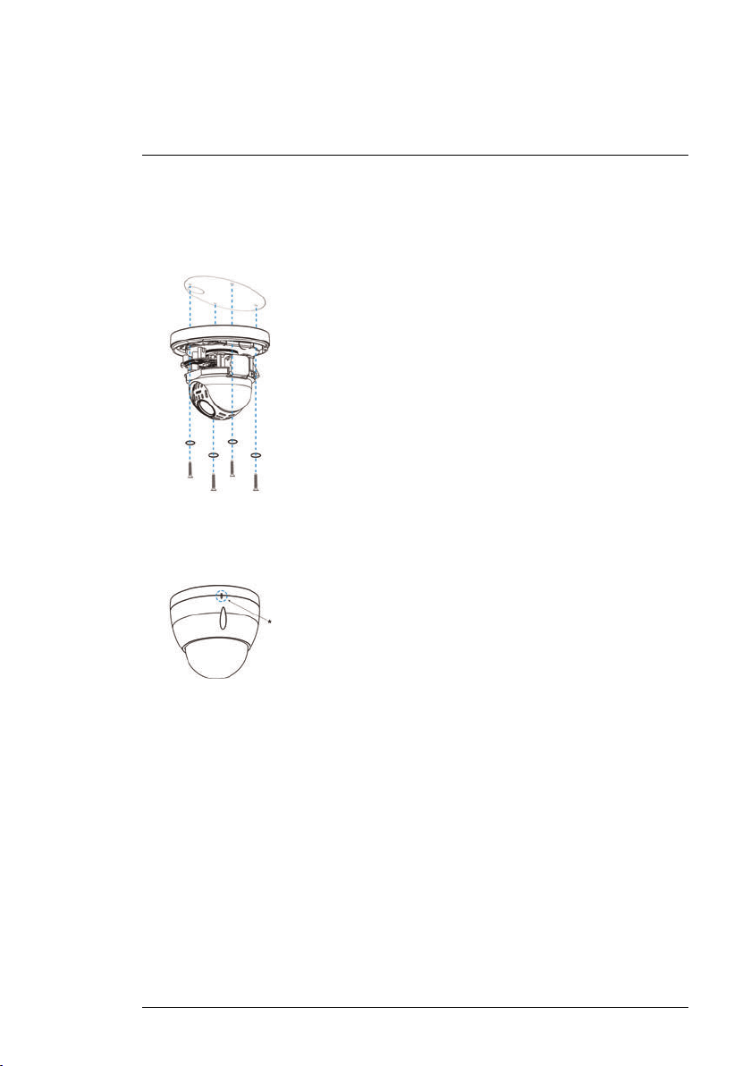
6. Push one of the included O-rings (x4) onto each of the included mounting
screws (x4). Attach the PTZ camera firmly to the ceiling using the included
mounting screws until the O-rings are flush against the camera base. Use
the included anchors if needed.
7. Re-attach the dome cover, ensuring that the rubber O-ring around the
camera base is in place and the alignment arrow* on the dome cover lines
up with the camera base.
8. Tighten the dome cover screws using the included Allen key.
9. Remove protective vinyl sheet from the dome cover once installation is
completed.
#LX400020; r.41770/42005; en-US
14

5
Controlling the PTZ Camera with an NVR
The camera can accept PTZ commands directly through the Ethernet cable.
There is no need to run special wiring to control the movement of the PTZ
camera.
The camera is compatible with LNR / NR / LNK Series NVRs, excluding the
LNR200 and LNR300 Series NVRs.
• For instructions on controlling the PTZ camera with the LNR / NR Series
NVRs, see 6 Controlling the PTZ camera with LNR / NR Series NVRs,
page 16
• For instructions on controlling the PTZ camera with the LNK Series NVRs,
see 7 Controlling the PTZ camera with LNK Series NVRs, page 22
#LX400020; r.41770/42005; en-US
15
6
Controlling the PTZ camera with LNR / NR Series NVRs
The following instructions are based on the LNR400 Series NVR. See your
NVR’s instruction manual for instructions on controlling the PTZ camera with
your system. For the latest list of compatible NVRs, please visit
www.lorextechnology.com/compatibility.
To connect the PTZ camera to the system:
1. Connect the camera to your NVR as detail in 3 Connecting the Camera,
page 3.
2. Right-click on the live view of the PTZ camera and click Main Menu. Enter
the system user name (default: admin) and password (default: 000000) if
prompted.
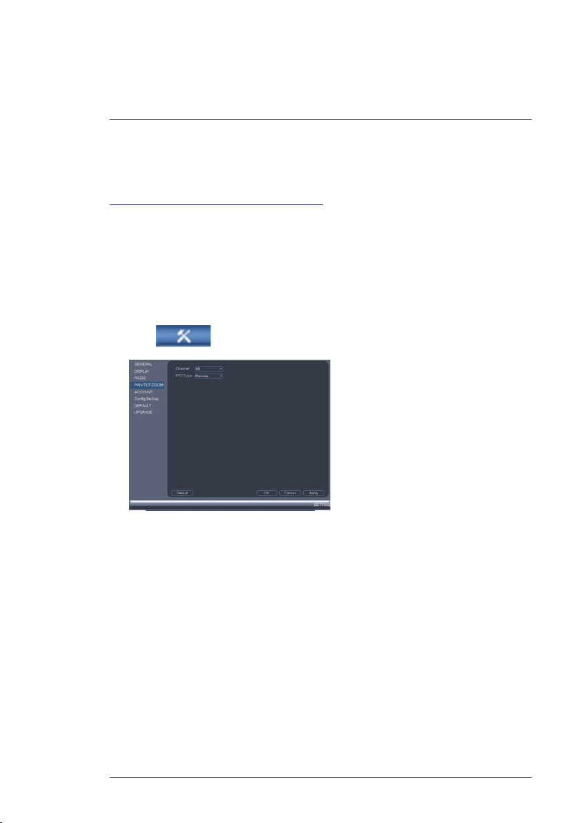
3. Click
4. Under Channel, select the channel your PTZ camera is connected to.
5. Under PTZ Type, select Remote.
6. Click OK. You can now control your PTZ camera using the system.
6.1 Controlling the PTZ Camera
1. In Live View, double-click the channel that has the PTZ camera connected
to open in full-screen.
2. Right-click and click PTZ. Enter the system user name and password if
prompted. The PTZ menu opens.
3. Use the on-screen PTZ controls to control the camera.
>Setting>Pan/Tilt/Zoom.
#LX400020; r.41770/42005; en-US
16
6
Controlling the PTZ camera with LNR / NR Series NVRs
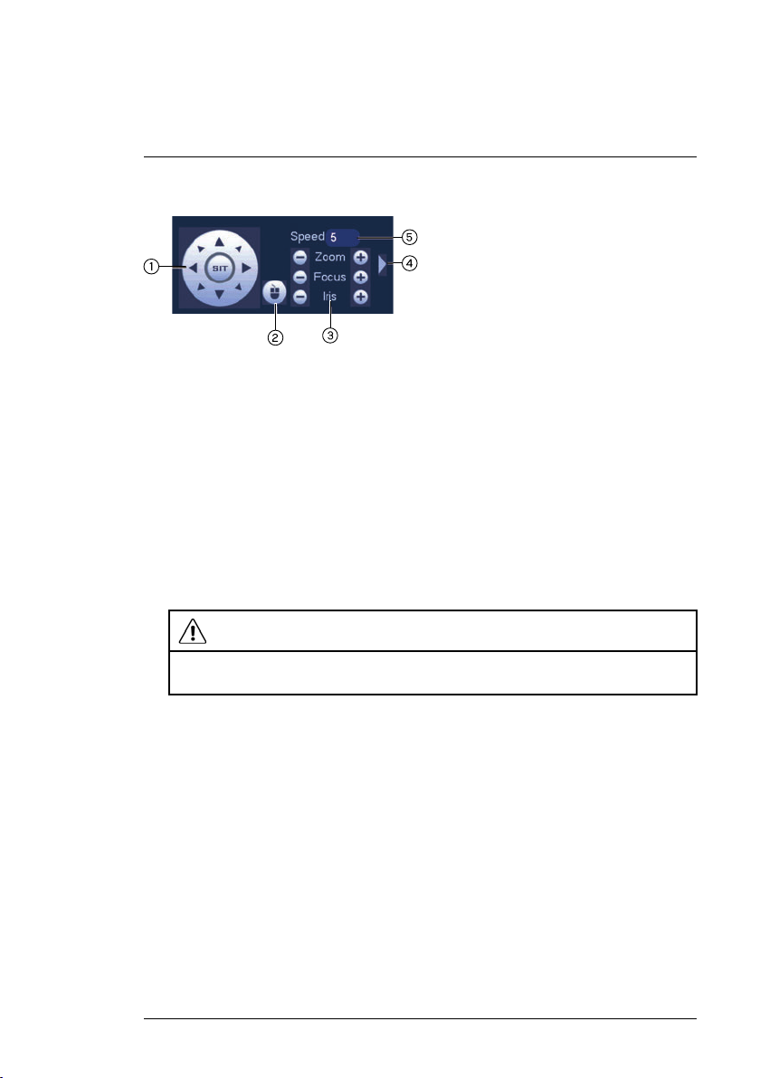
PTZ Controls
1. Direction keys: Click to pan and tilt the camera. Click SIT to stop the current action.
2. Mouse PTZ: Click to activate mouse PTZ mode. In mouse PTZ mode:
• Click and drag to move the camera.
• Use the scroll wheel to zoom in and out.
• Right-click to exit and return to normal PTZ controls.
3. Zoom/Focus/Iris: Click +/- to adjust the zoom, focus, and iris. Adjusting
the camera’s iris settings allow you to control the amount of light that enters the camera’s lens. The higher the iris value, the greater the amount of
light that enters the camera’s lens.
CAUTION
Adjust the camera’s iris settings to match the environment where the camera is installed. Too much light exposure might result in a very bright camera image.
4. Advanced controls: Click to open advanced PTZ controls.
5. Speed: Enter a PTZ speed between 1 (slowest) and 8 (fastest).
6.2 Advanced PTZ Controls
Advanced PTZ controls can be used to save camera positions and cycle
through various positions, and automate camera actions.
To open advanced PTZ controls:
• Click the arrow in the PTZ control window to open advanced controls.
#LX400020; r.41770/42005; en-US
17

6
Controlling the PTZ camera with LNR / NR Series NVRs
Advanced PTZ controls overview:
1. No.: Click to select the number of the action you want to perform.
2. Not supported.
3. PTZ camera menu: Click to open the camera’s OSD menu. This menu is
for advanced users only.
4. Preset: Click to call the selected preset.
5. Autopan: Click to start autopan. During autopan, the camera will continuously pan 360°.
6. Tour: Click to run the selected tour.
7. Not supported.
8. Pattern: Click to run the selected pattern.
9. Not supported
10. Auto scan: Click to run the selected autoscan.
11.
: Click to open the PAN/TILT/ZOOM menu, where you can set up
Presets, Tours, Patterns, and Auto Scans.
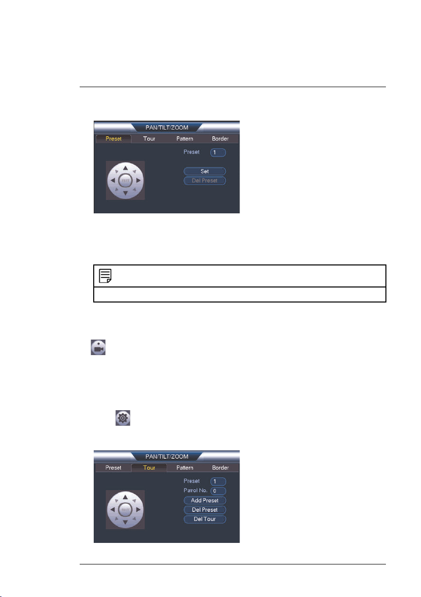
6.2.1 Presets
Presets will save a camera position for quick retrieval.
To add presets:
1. Click
#LX400020; r.41770/42005; en-US
to open the PAN/TILT/ZOOM menu.
18
6
Controlling the PTZ camera with LNR / NR Series NVRs
2. Click the Preset tab.
3. Under the Preset text box, enter the number of the preset you want to
create.
4. Move the camera to the desired position and click Set.
NOTE
Click Del Preset to delete a preset.
To go to a preset:
• Under No., select the number of the preset you would like to go to and click
.
6.2.2 Tours
Tours will cycle through a set of presets.
To create a tour:
1. Click
to open the PAN/TILT/ZOOM menu.
2. Click the Tour tab.
#LX400020; r.41770/42005; en-US
19
6
Controlling the PTZ camera with LNR / NR Series NVRs
3. Under Patrol No., select the tour you would like to configure.
4. Under Preset, select a preset you would like to add to the tour.
5. Click Add Preset.
6. Repeat steps 4 and 5 to add additional presets to the tour.
NOTE
Click Del Tour to clear all presets from a tour.
To run a tour:
• Under No., select the number of the tour you would like to go to and click
.
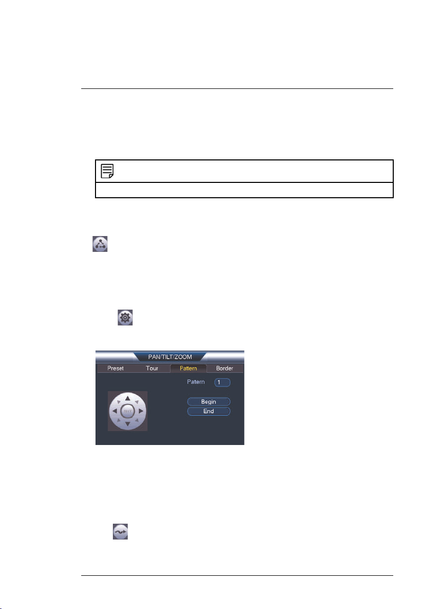
6.2.3 Pattern
Patterns automatically cycle the camera between two positions.
To create a pattern:
1. Click
to open the PAN/TILT/ZOOM menu.
2. Click the Pattern tab.
3. Under Pattern, enter the pattern you would like to configure.
4. Move the camera into the desired start position and click Begin.
5. Move the camera into the desired end position and click End.
To run a pattern:
• Under No., select the number of the pattern you would like to go to and
click
#LX400020; r.41770/42005; en-US
.
20
6
Controlling the PTZ camera with LNR / NR Series NVRs
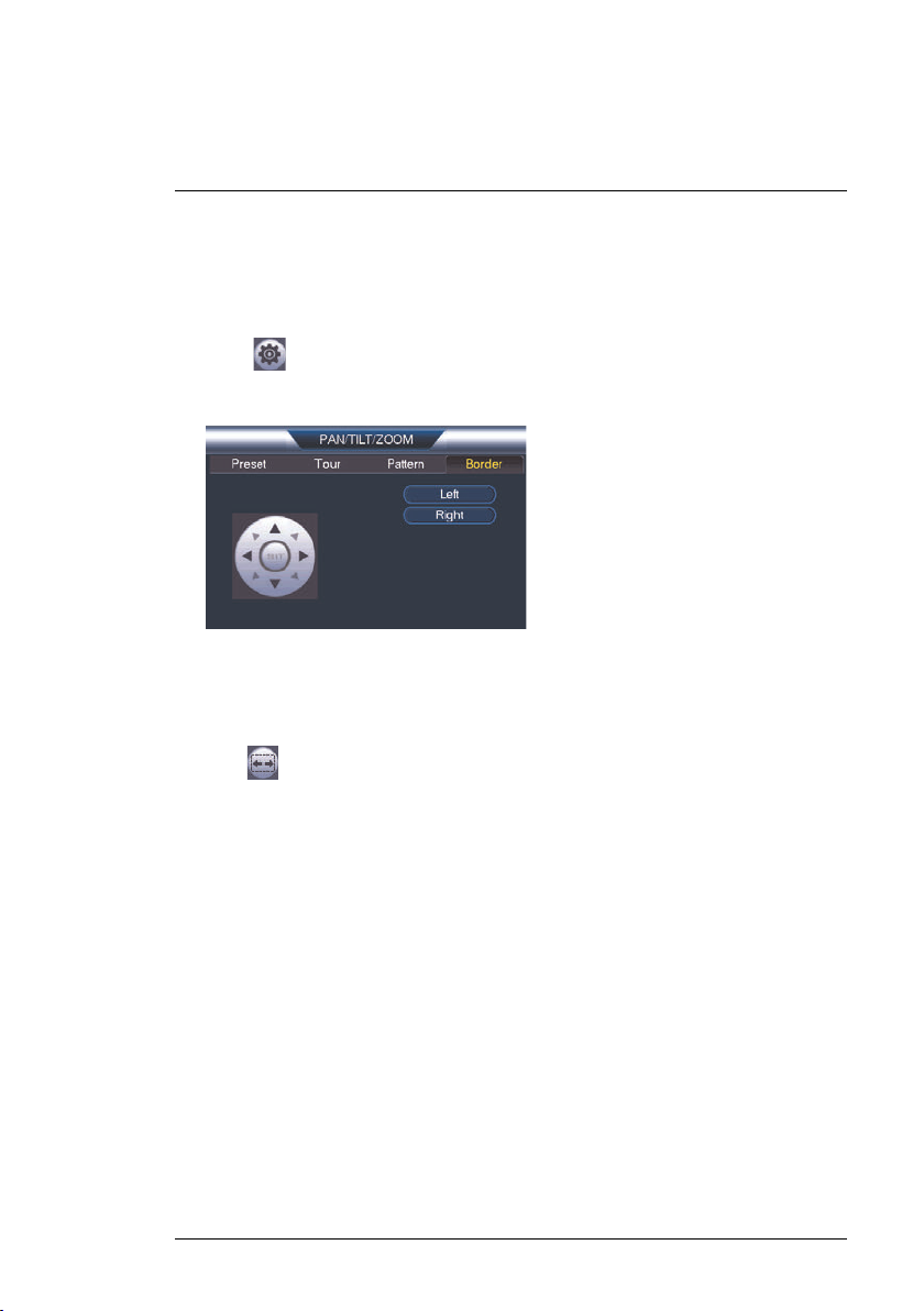
6.2.4 Auto Scan
An auto scan automatically cycles between a left and right point.
To create a new auto scan:
1. Click
to open the PAN/TILT/ZOOM menu.
2. Click the Border tab.
3. Move the camera into the desired left position and click Left.
4. Move the camera into the desired right position and click Right.
To run an auto scan:
• Click
.
#LX400020; r.41770/42005; en-US
21
7
Controlling the PTZ camera with LNK Series NVRs
The following instructions are based on the LNK7000 Series NVR. See your
NVR’s instruction manual for instructions on controlling the PTZ camera with
your system. For the latest list of compatible NVRs, please visit
www.lorextechnology.com/compatibility.
To connect the PTZ camera to the system:
1. Connect the camera to your NVR as detailed in 3 Connecting the Camera.
2. Right-click anywhere on the live viewing mode to open the Quick Menu,
then select Main Menu.
NOTE
If prompted, enter the system user name (default: admin) and your password.
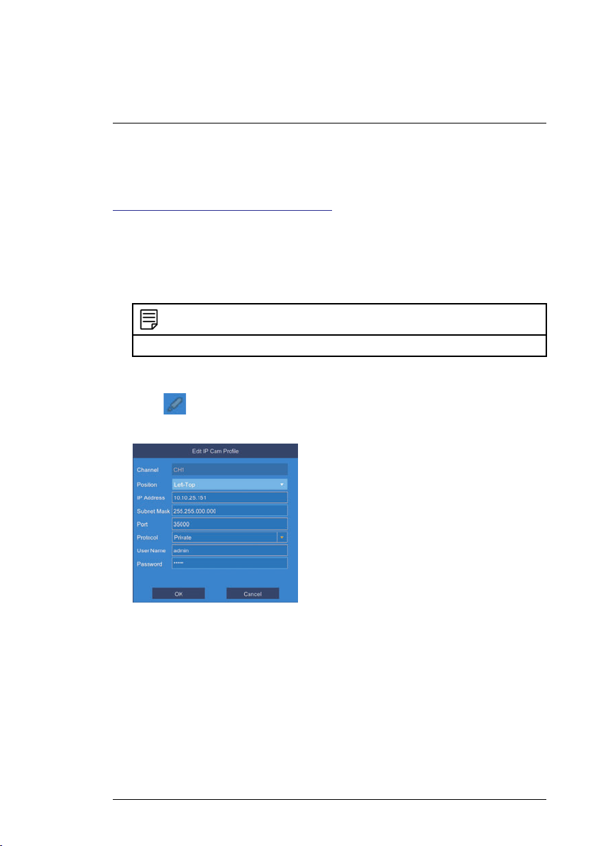
3. Under Settings, click Display to open the IP Camera tab.
4. Click
attributes appear.
5. Under Protocol, select ONVIF.
6. Click OK to save changes.
7.1 Controlling the PTZ camera
To access the PTZ controls:
• Right-click on the live viewing area for the PTZ camera to open the Quick
Menu, then click PTZ.
OR
#LX400020; r.41770/42005; en-US
next to the connected PTZ camera you want to edit. The camera
22
7
Controlling the PTZ camera with LNK Series NVRs
• Hover the mouse near the top of the live viewing area for the PTZ camera
to reveal the Mini Menu, then click
NOTE
If prompted, enter the user name (default: admin) and your secure password.
.
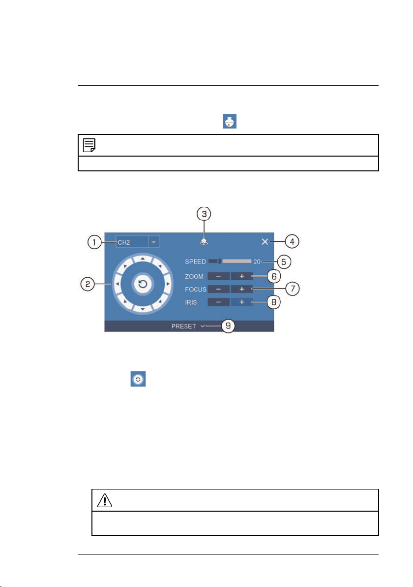
To use the PTZ controls:
1. Channel: Select the channel of the PTZ camera you want to control.
2. Navigation Controls: Click the directional arrows to move the PTZ cam-
era. Click
to begin autopan (PTZ camera pans around automatically).
3. Start Cruise: Cycles between preset viewing points automatically.
4. Close PTZ Controls
5. Speed: Set the speed of the PTZ camera’s movement.
6. Zoom: Click –/+ to zoom in or out.
7. Focus: Click –/+ to adjust the focus.
8. Iris: Click –/+ to set the iris. Adjusting the camera’s iris settings allow you
to control the amount of light that enters the camera’s lens. The higher the
iris value, the greater the amount of light that enters the camera’s lens.
CAUTION
Adjust the camera’s iris settings to match the environment where the camera is installed. Too much light exposure might result in a very bright camera image.
#LX400020; r.41770/42005; en-US
23
7
Controlling the PTZ camera with LNK Series NVRs
9. Preset: Click to access preset settings. For details on setting presets, see
7.1.1 Setting PTZ Presets, page 24
7.1.1 Setting PTZ Presets
Access the PTZ control menu to set preset viewing points for the PTZ. This is
helpful for saving frequently-monitored areas for quick viewing. Once you
have saved a few preset viewing points, you can start a PTZ cruise to switch
between preset points automatically by clicking
.
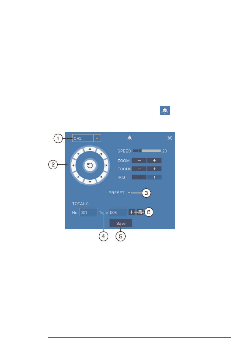
To set PTZ presets:
1. Select the channel for the PTZ camera you want to set presets for.
2. Use the directional arrows to move the PTZ camera to the desired view for
the preset.
3. Click the arrow next to PRESET to reveal preset controls.
4. In the field next to Time, enter an amount of time in seconds. This will determine how long the PTZ camera looks at the preset area before switching to the next preset in a cruise.
5. Click Save to confirm the current preset point.
#LX400020; r.41770/42005; en-US
24
7
Controlling the PTZ camera with LNK Series NVRs
6. Click + to move to the next preset number in the No. field. Repeat for as
many preset points as you wish to add.
NOTE
• Each preset viewing area you add to the system must have a unique ID number
(No.). Using the same ID number as an existing preset will result in the old preset
being overwritten.
• To cycle through preset viewing points automatically, click
Cruise. Ensure you have enabled cruise on the selected PTZ camera (see 7.1
Controlling the PTZ camera, page 22 for details).
• Click
to delete a preset.
to start PTZ
#LX400020; r.41770/42005; en-US
25

8
Technical Specifications
Image Sensor 1/3", 2.1MP CMOS (LNZ32P12)
1/2.7", 2.1MP CMOS (LNZ32P12S)
Video Format NTSC / PAL
Effective Pixels 1920 (H) x 1080 (V)
Resolution Up to 1080p
Range 360° Pan (Endless); 0–90° Tilt (Auto-Flip)
Pan/Tilt Speed Max 300°/Sec Pan; Max 200°/Sec Tilt.
Zoom
Min. Illumination 0.05 Lux in Color; 0.005 Lux in Black and White
Lens / Lens Type Auto Focus / 5.1 – 61.2mm F1.6 – F2.3
Field of View (Horizontal) 4° ~ 51° (LNZ32P12)
Scan System
Synchronization
Iris Auto Iris
S / N Ratio >55dB (AGC Off)
Termination
Power Requirement PoE+ (Power over Ethernet, Class 4)
Power Consumption Max. 750mA
Operating Temperature Range 14°F ~ 140°F / -10°C ~ 60°C (LNZ32P12)
Operating Humidity Range
Indoor/Outdoor Both (IP66)
Weight (Camera Alone)
Weight (Camera & Wall Mount)
12x Optical Zoom & 16x Digital Zoom
5° ~ 60° (LNZ32P12S)
Progressive
Internal
RJ45 10 M / 100M Ethernet
1
; 24V AC
-22°F ~ 140°F / -30°C ~ 60°C (LNZ32P12S)
Within 90%RH
2
4.0lbs / 1.8kg
5.7lbs / 2.6kg
1. Compatible with all Lorex HD NVRs except for LNR200 & LNR300 Series.
2. Not intended for submersion in water. Installation in a sheltered location recommended.
#LX400020; r.41770/42005; en-US
26
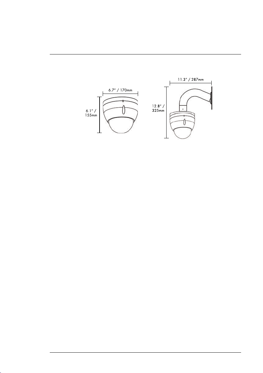
8
Technical Specifications
8.1 Dimensions
#LX400020; r.41770/42005; en-US
27
 Loading...