

Page 1
Instruction Manual
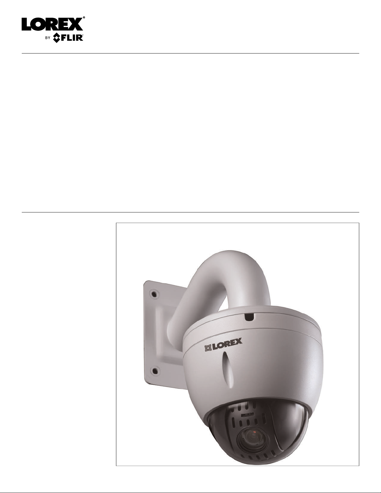
LNZ32P12 12X Network
PTZ Camera Series
LNZ32P12_SERIES_MANUAL_TRILINGUAL_R2
Page 2
Thank you for purchasing this product. Lorex Corporation is committed to providing our customers with a
high quality, reliable security solution.
This manual refers to the following models:
LNZ32P12
LNZ32P12S
For the latest online manual, downloads and product updates, and to learn about our complete line of
accessory products, please visit our website at:
www.lorextechnology.com
WARNING
RISK OF ELECTRIC SHOCK
DO NOT OPEN
WARNING: TO REDUCE THE RISKOF ELECTRIC SHOCK DO NOT REMOVE
COVER. NO USER SERVICEABLE PARTS INSIDE.
REFER SERVICING TO QUALIFIED SERVICE PERSONNEL.
The lightning flash with arrowhead symbol, within an equilateral
triangle, is intended to alert the user to the presence of uninsulated
"dangerous voltage" within the product’s enclosure that may be of
sufficient magnitude to constitute a risk of electric shock.
The exclamation point within an equilateral triangle is intended to
alert the user to the presence of important operating and
maintenance (servicing) instructions in the literature accompanying
the appliance.
WARNING: TO PREVENT FIRE OR SHOCK HAZARD, DO NOT EXPOSE THIS UNIT
TO RAIN OR MOISTURE.
CAUTION: TO PREVENT ELECTRIC SHOCK, MATCH WIDE BLADE OF THE PLUG
TO THE WIDE SLOT AND FULLY INSERT.
#LX400020; r.35429/35429; en-US
iv
Page 3

Table of contents
1 Safety Instructions ..............................................................................1
2 Getting Started....................................................................................2
3 Connecting the Camera........................................................................3
3.1 Option 1: Connecting the Camera to an NVR .................................... 3
3.2 Connecting Cameras to the Local Area Network (LAN) .......................3
4 Installation .........................................................................................7
4.1 Installation Tips and Warnings .......................................................7
4.2 Installation (Indoor/Outdoor)..........................................................7
5 Controlling the PTZ Camera with an NVR.............................................. 13
5.1 Controlling a PTZ Camera (Local NVR) ......................................... 13
5.2 Advanced PTZ Controls ............................................................. 14
5.2.1 Presets ........................................................................ 15
5.2.2 Tours ........................................................................... 15
5.2.3 Pattern......................................................................... 16
5.2.4 Auto Scan .................................................................... 16
6 Technical Specifications..................................................................... 18
6.1 Dimensions ............................................................................. 18
7 Troubleshooting ................................................................................ 19
8 Resetting the Camera ........................................................................ 20
#LX400020; r.35429/35429; en-US
v
Page 4

1
Safety Instructions
• Read this guide carefully and keep it for future reference.
• Follow all instructions for safe use of the product and handle with care.
• Use the camera within given temperature, humidity, and voltage levels noted in the
Technical Specifications.
• Camera is rated for outdoor use and is weatherproof when properly installed. Camera
is not intended for submersion in water. Installation under a sheltered environment is
recommended.
• Do not disassemble the camera.
• Do not point the camera directly towards the sun or a source of intense light.
• Use only the supplied regulated power supply. Use of a non-regulated, non-conforming
power supply can damage this product and voids the warranty.
• Make sure to install the camera in a location that can support the camera weight. If
mounting the camera on a drywall surface, you must drill at least 2 of the mounting
screws through a wooden stud. See 4.2 Installation (Indoor/Outdoor), page 7 for complete installation instructions.
• Make sure there are no live electrical cables in the area where you plan to mount the
camera.
• Periodic cleaning may be required. Use a damp cloth only. Do not use anything other
than water to clean the dome cover, as chemicals such as acetone can permanently
damage the plastic.
#LX400020; r.35429/35429; en-US
1
Page 5
2
Getting Started
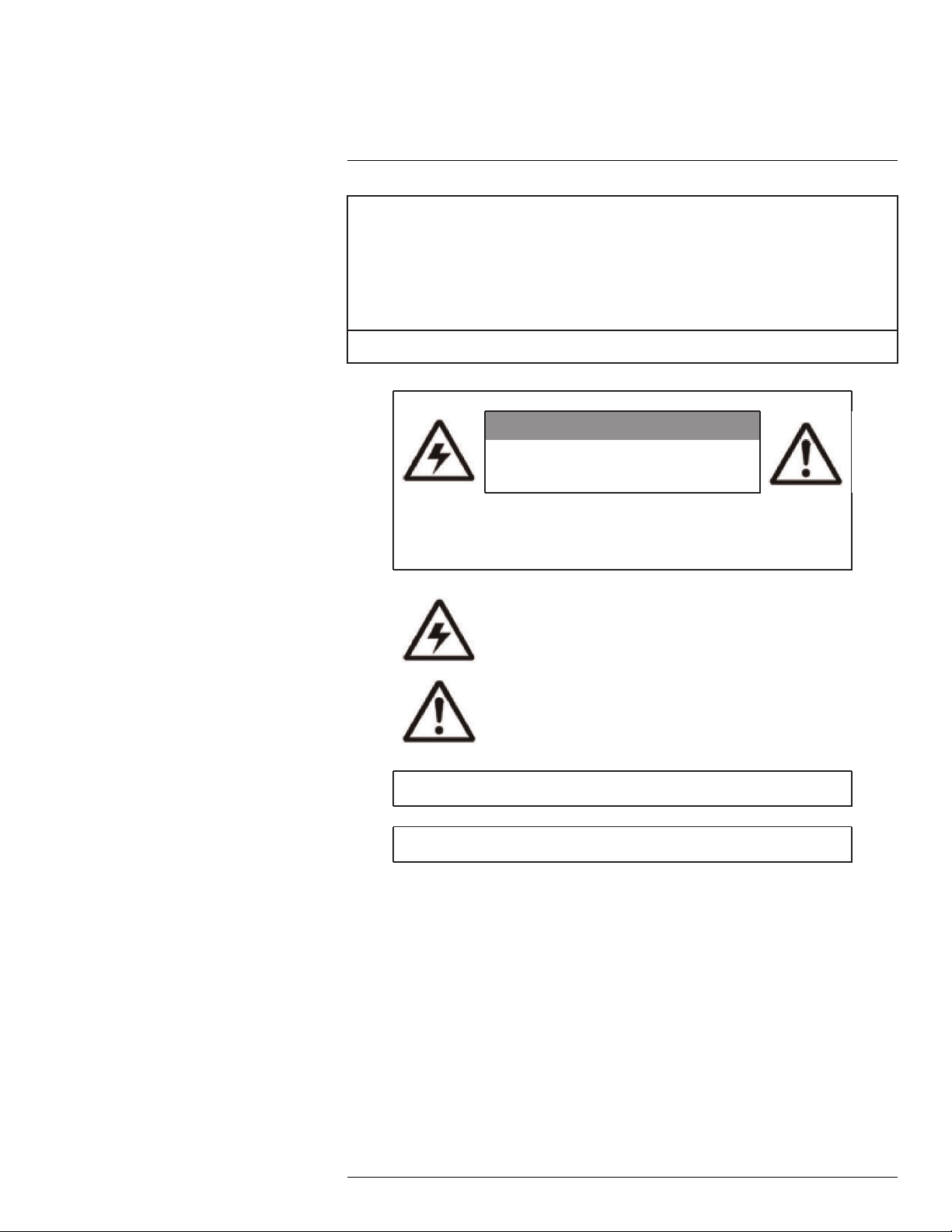
The system comes with the following components:
PTZ Camera Wall Mount
100ft (30.5m) Cat5e UL
Compliant Ethernet Extension
Cable
4x O-Rings
Power Adapter
4x Allen Bolts
Pendant Cap
Mounting Screws
& Anchors
Allen Key
Mounting Template
#LX400020; r.35429/35429; en-US
Instruction Manual
2
Page 6
3
Connecting the Camera
NOTE
It is recommended to connect the camera to your NVR and test the PTZ controls before permanent installation. For instructions on how to set up PTZ controls, see 5 Controlling the PTZ Camera with an NVR,
page 13.
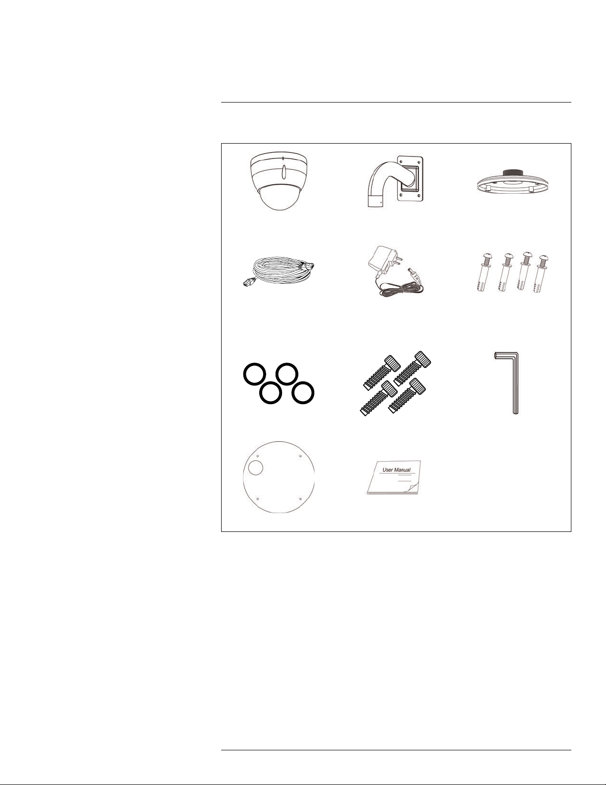
3.1 Option 1: Connecting the Camera to an NVR
1. Connect the PoE+ connector on the camera cable to the included Ethernet extension
cable.
2. Connect the Ethernet extension cable to one of the PoE+ ports on the back panel of
your NVR.
NOTE
You can use up to a 300ft (91m) CAT5e Ethernet cable to connect the camera to your NVR. The camera
is compatible with all Lorex HD NVRs except for LNR200 & LNR300 Series. For the most up-to-date list
of compatible recorders, visit www.lorextechnology.com/support.
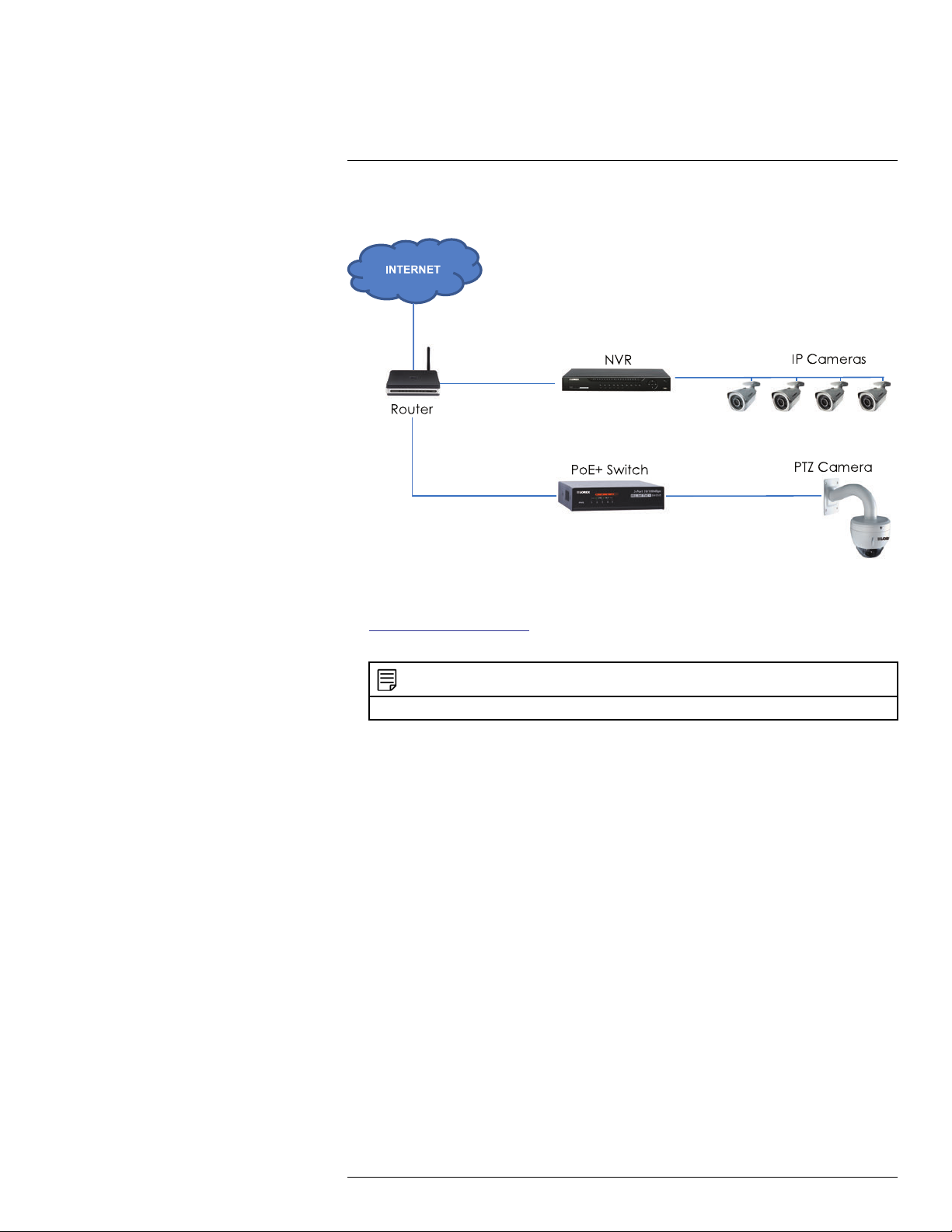
3.2 Connecting Cameras to the Local Area Network (LAN)
For flexibility, you may also connect the camera to the same Local Area Network (LAN) as
the NVR. This is accomplished by connecting the camera to the same router as the NVR.
For these installations, an external PoE+ switch (sold separately) or power adapter (included) must be used to provide power to the camera. You also must add the camera on
the NVR before it will show a picture on the monitor or be recorded by the NVR.
What is PoE+?
PoE (Power over Ethernet) is a technology that allows Ethernet cables to carry electrical
power to connected devices. High-powered devices such as PTZ cameras use PoE+ (also
known as PoE class 4 or IEEE 802.3at), which provides more power to connected devices
than standard PoE. Compatible NVRs use integrated PoE+ ports to provide power and
PTZ commands to the camera, as well as video connection to the NVR. PoE+ ports will
provide up to 30W to each connected device, whereas standard PoE (class 3) ports only
provide up to 15W. In order to use this PoE+ rated camera without the included power
adapter, you must connect it directly to a compatible NVR (compatible with all Lorex HD
NVRs except for LNR200 & LNR300 Series. For the most up-to-date list of compatible recorders, visit www.lorextechnology.com/support) or a PoE+ switch on the same network
as the NVR. PoE+ switches are available for purchase on www.lorextechnology.com (mod-
el #: ACCLPS241B).
Complete the following steps to connect the camera to the NVR over the LAN.
#LX400020; r.35429/35429; en-US
3
Page 7
3
Connecting the Camera
Step 1 of 2 — Option A: Connecting the camera to your local network using an optional PoE+ switch:
1. Connect an Ethernet cable of up to 300ft (91m) rated CAT5e or higher (not included)
from the LAN port on an external PoE+ switch (sold separately on
www.lorextechnology.com) to your router. Connect the power cable to the PoE+ switch
and to a power outlet or surge protector.
NOTE
Terminology may vary depending on the model of PoE+ switch you have.
2. Connect the camera to the PoE+ switch using the included Ethernet cable (or a CAT5e
Ethernet cable of up to 300ft (91m)). The PoE+ switch will provide power and video
transmission the same way as your NVR.
#LX400020; r.35429/35429; en-US
4
Page 8
3
Connecting the Camera
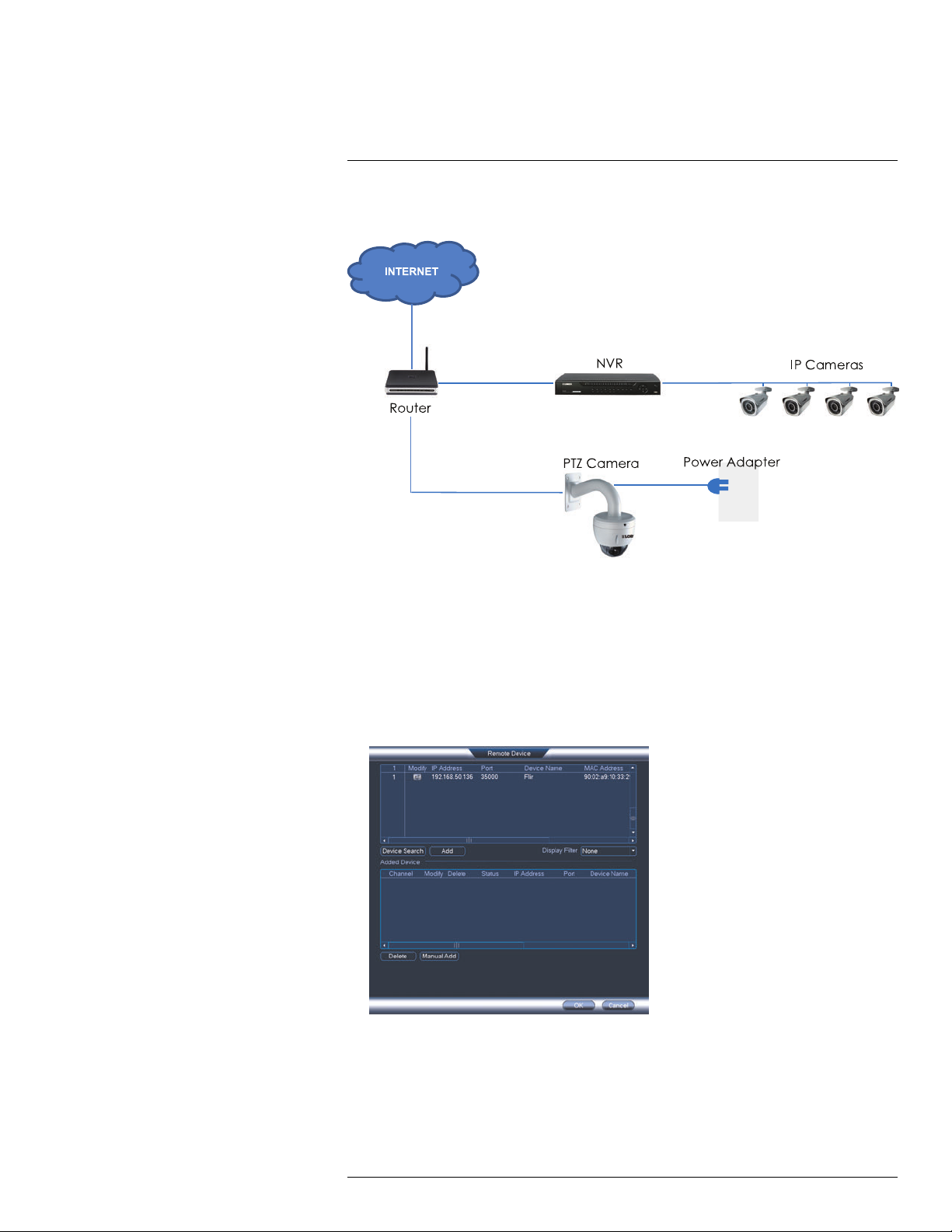
Step 1 of 2 — Option B: Connecting the camera to your local network using power
adapters:
1. Connect the camera to the included power adapter.
2. Connect the camera to a router in the same network as your NVR using the included
Ethernet cable (or an Ethernet cable of up to 300ft (91m) rated CAT5e or higher).
Step 2 of 2: Add the camera to your NVR:
1. Right-click and select Device Search .
2. Log in using the admin account (default User Name: admin; default Password:
000000).
3. Click Device Search. The system searches the network for compatible cameras.
4. Check the camera(s) you would like to add.
#LX400020; r.35429/35429; en-US
5
Page 9
3
Connecting the Camera
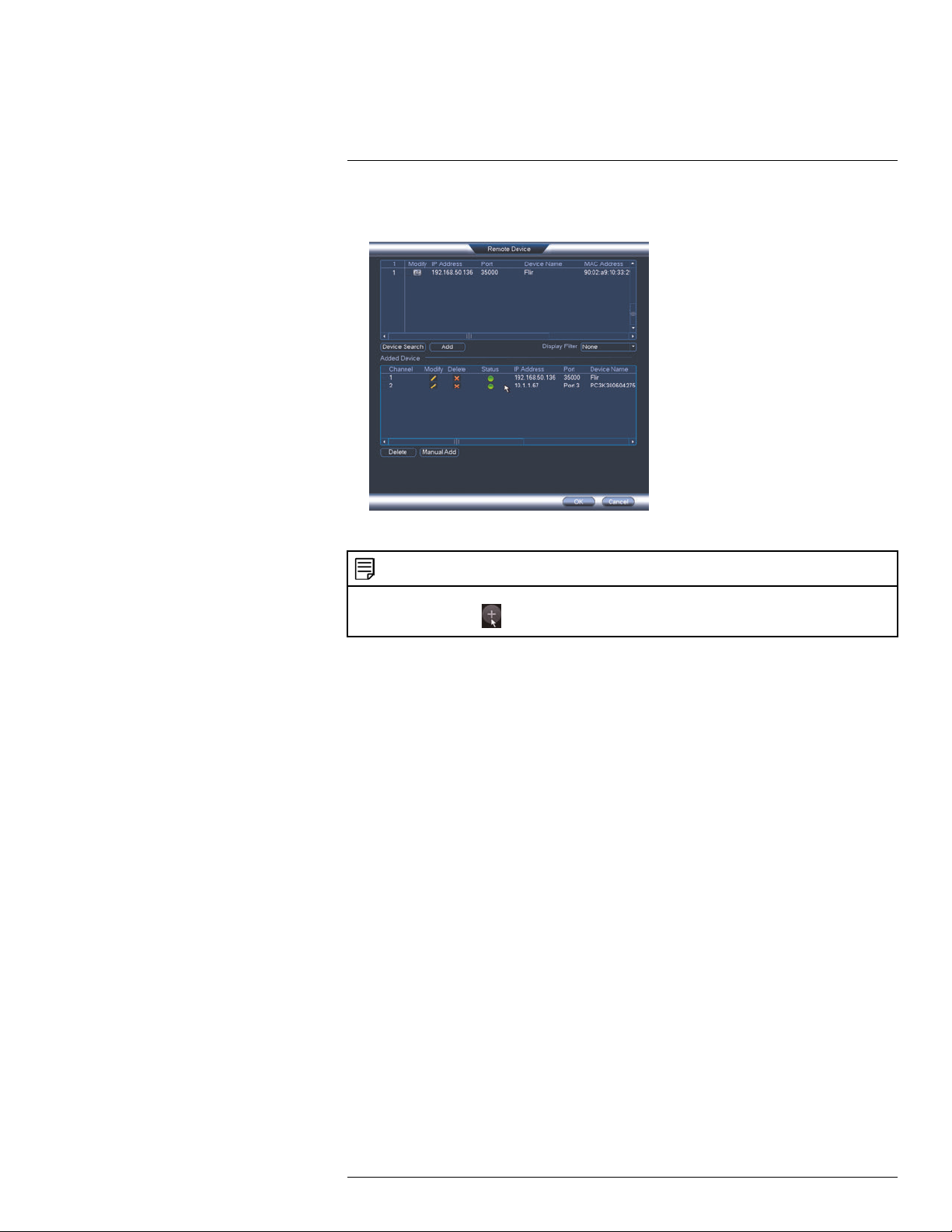
5. Click Add. The Status indicator turns green to show the camera is successfully
connected.
6. Click OK to save changes.
NOTE
You can also add a camera to a specific channel by hovering the mouse over an empty channel in split-
screen view and clicking
. Then double-click the camera you would like to add and right click to exit.
#LX400020; r.35429/35429; en-US
6
Page 10

4
Installation
4.1 Installation Tips and Warnings
WARNING
Make sure to install the camera in a location that can support the camera weight. If mounting the camera
on a drywall surface, you must drill the mounting screws through a wooden stud. See 4.2 Installation (Indoor/Outdoor), page 7 for full installation instructions.
• Camera is rated for outdoor use. It is recommended to install the camera in a sheltered
area, such as under the eaves on a roof.
• It is recommended to install the camera as high up as possible to get the best possible
image.
• Camera is capable of seeing in low light conditions (0.05 Lux), but it cannot see in total
darkness. It is recommended to install the camera where there is some ambient light (e.
g. street lighting or starlight, moonlight, etc.) or leave some lighting on in the area where
the camera is installed.
• Mount the camera where the lens is away from direct and intense sunlight.
• Plan your cable wiring so that it does not interfere with power lines or telephone lines.
• Ensure you adhere to local building codes.
• Ensure that the camera wiring is not exposed or easily cut.
• Mount the camera in an area that is visible but out of reach.
NOTE
This camera is suitable for wall and ceiling mounting.
4.2 Installation (Indoor/Outdoor)
To install the camera on a wall:
CAUTION
Make sure to disconnect power before installing the camera. Camera will begin moving immediately when
power is connected.
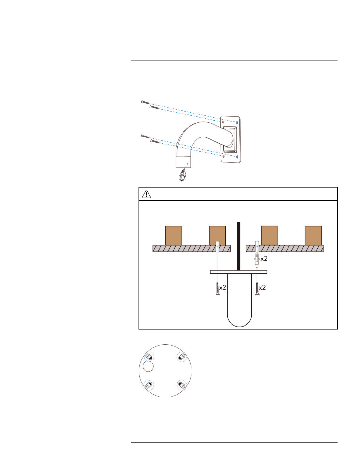
1. Mark holes for the mounting screws (x4) and cables through the wall mount bracket.
Drill where marked.
2. Pull the Ethernet cable from your NVR, PoE+ switch or router through the hole in the
mounting surface.
#LX400020; r.35429/35429; en-US
7
Page 11
Installation4
3. Pull the Ethernet cable through the wall mount bracket. Firmly attach the wall mount
bracket to the wall using the included mounting screws (x4) and the included anchors
(x4) if needed.
WARNING
Make sure to install the wall mount bracket in a location that can support the camera’s weight. If
mounting the camera on a drywall surface, you must drill at least 2 of the mounting screws through a
wooden stud to ensure a stable mount. See the diagram below for details.
4. Remove plastic film from the screw holes on the bottom of the camera.
#LX400020; r.35429/35429; en-US
8
Page 12
Installation4
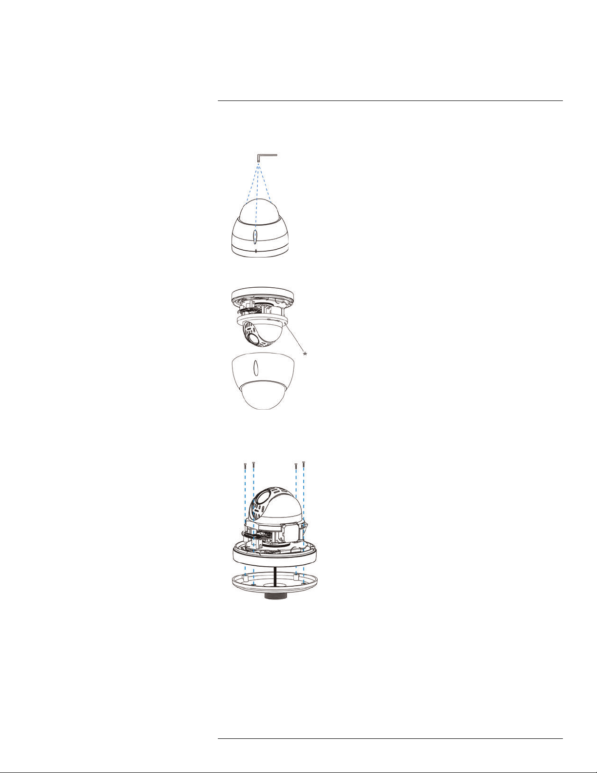
5. Use the included Allen key to loosen the dome cover screws (x3). Remove the dome
cover.
6. Remove the foam ring* around the camera module.
7. Pull the camera cables through the hole in the pendant cap. Use the included Allen
bolts (x4) to attach the PTZ camera base firmly to the pendant cap. Tighten using the
included Allen key.
#LX400020; r.35429/35429; en-US
9
Page 13
Installation4
8. Re-attach the dome cover, ensuring that the rubber O-ring around the camera base is
in place and the alignment arrow* on the dome cover lines up with the camera base.
9. Tighten the dome cover screws (x3) using the included Allen key.
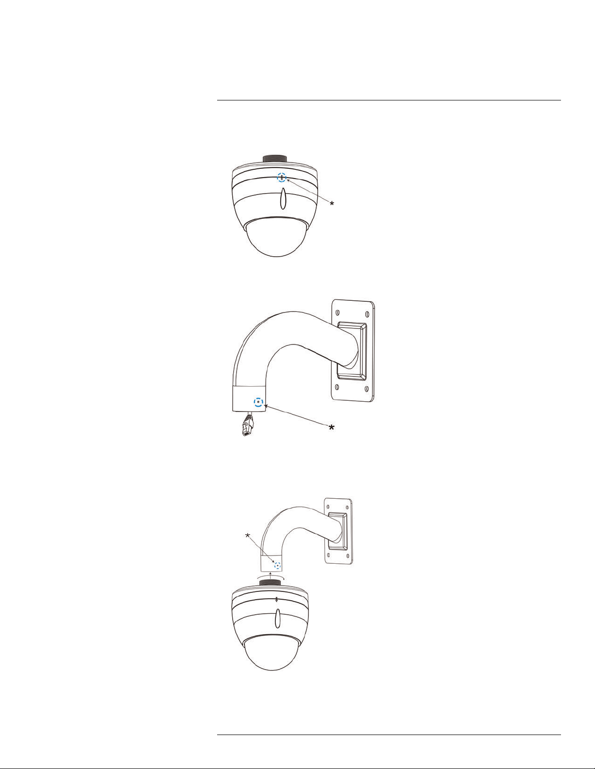
10. Loosen the security screw* on the wall mount bracket.
11. Connect the camera to the cabling in the wall mount bracket. See 3 Connecting the
Camera, page 3 for full connection instructions.
12. Twist the pendant cap onto the wall mount bracket. Tighten the security screw* on the
wall mount bracket.
13. Remove protective vinyl sheet from the dome cover once installation is completed.
#LX400020; r.35429/35429; en-US
10
Page 14
Installation4
To install the camera on a ceiling:
CAUTION
• Make sure to disconnect power before installing the camera. Camera will begin moving immediately
when power is connected.
• Make sure to install the camera in a location that can support the camera weight.
1. Remove plastic film from the screw holes on the bottom of the camera.
2. Use the included mounting template to mark holes for the mounting screws and cables
if needed. Drill where marked.
NOTE
If you run the cables along the mounting surface, you must run the cable through the cable notch on
the base of the camera. This will keep the camera base flush to the surface when mounted.
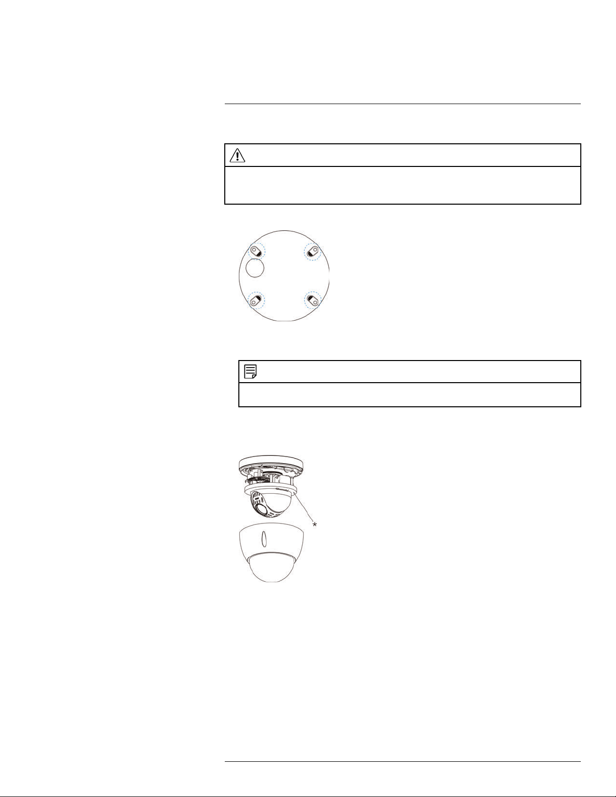
3. Use the included Allen key to loosen the dome cover screws (x3). Remove the dome
cover.
4. Remove the foam ring* around the camera module.
5. Connect the camera to the cabling in the ceiling. See 3 Connecting the Camera, page
3 for full connection instructions.
#LX400020; r.35429/35429; en-US
11
Page 15
Installation4
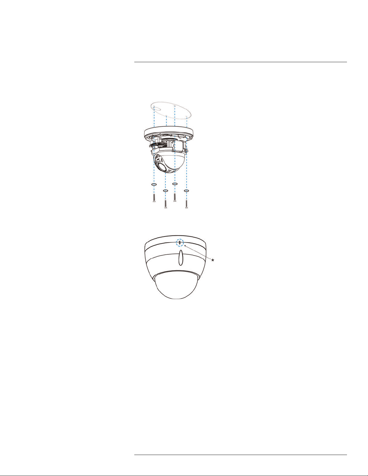
6. Push one of the included O-rings (x4) onto each of the included mounting screws (x4).
Attach the PTZ camera firmly to the ceiling using the included mounting screws until
the O-rings are flush against the camera base. Use the included anchors if needed.
7. Re-attach the dome cover, ensuring that the rubber O-ring around the camera base is
in place and the alignment arrow* on the dome cover lines up with the camera base.
8. Tighten the dome cover screws using the included Allen key.
9. Remove protective vinyl sheet from the dome cover once installation is completed.
#LX400020; r.35429/35429; en-US
12
Page 16
5
Controlling the PTZ Camera with an NVR
The camera can accept PTZ commands directly through the Ethernet cable. There is no
need to run special wiring to control the movement of the PTZ camera.
NOTE
For the latest list of compatible NVRs, please visit www.lorextechnology.com/support.
To connect a PTZ camera to the system:
1. Connect the camera to your NVR as detail in 3 Connecting the Camera, page 3.
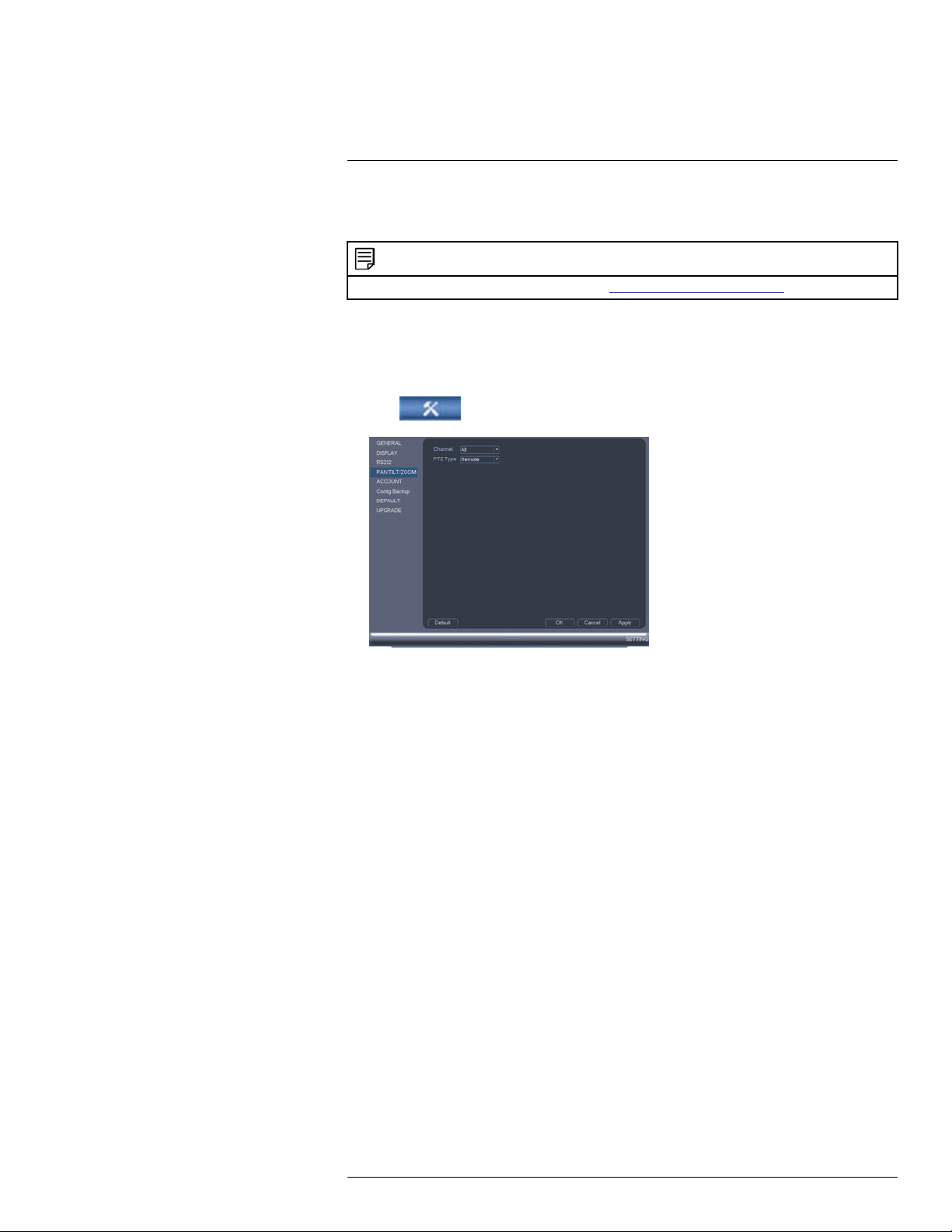
2. Right-click and click Main Menu. Enter the system user name (default: admin) and
password (default: 000000) if prompted.
3. Click
4. Under Channel, select the channel your PTZ camera is connected to.
5. Under PTZ Type, select Remote.
6. Click OK. You can now control your PTZ camera using the system.
5.1 Controlling a PTZ Camera (Local NVR)
1. In Live View, double-click the channel that has the PTZ camera connected to open in
full-screen.
2. Right-click and click PTZ. Enter the system user name and password if prompted. The
PTZ menu opens.
3. Use the on-screen PTZ controls to control the camera.
>Setting>Pan/Tilt/Zoom.
#LX400020; r.35429/35429; en-US
13
Page 17

5
Controlling the PTZ Camera with an NVR
PTZ Controls
1. Direction keys: Click to pan and tilt the camera. Click SIT to stop the current action.
2. Mouse PTZ: Click to activate mouse PTZ mode. In mouse PTZ mode:
• Click and drag to move the camera.
• Use the scroll wheel to zoom in and out.
• Right-click to exit and return to normal PTZ controls.
3. Zoom/Focus/Iris: Click +/- to adjust the zoom, focus, and iris.
4. Advanced controls: Click to open advanced PTZ controls.
5. Speed: Enter a PTZ speed between 1 (slowest) and 8 (fastest).
5.2 Advanced PTZ Controls
Advanced PTZ controls can be used to save camera positions and cycle through various
positions, and automate camera actions.
To open advanced PTZ controls:
• Click the arrow in the PTZ control window to open advanced controls.
Advanced PTZ controls overview:
1. No.: Select the number of the action you want to perform.
2. Not supported.
3. PTZ camera menu: Click to open the camera’s OSD menu. This menu is for advanced
users only.
4. Preset: Click to call the selected preset.
#LX400020; r.35429/35429; en-US
14
Page 18
5
Controlling the PTZ Camera with an NVR
5. Autopan: Click to start autopan. During autopan, the camera will continuously pan
360°.
6. Tour: Click to run the selected tour.
7. Not supported.
8. Pattern: Click to run the selected pattern.
9. Not supported
10. Auto scan: Click to run the selected autoscan.
11.
: Click to open the PAN/TILT/ZOOM menu, where you can set up Presets, Tours,
Patterns, and Auto Scans.
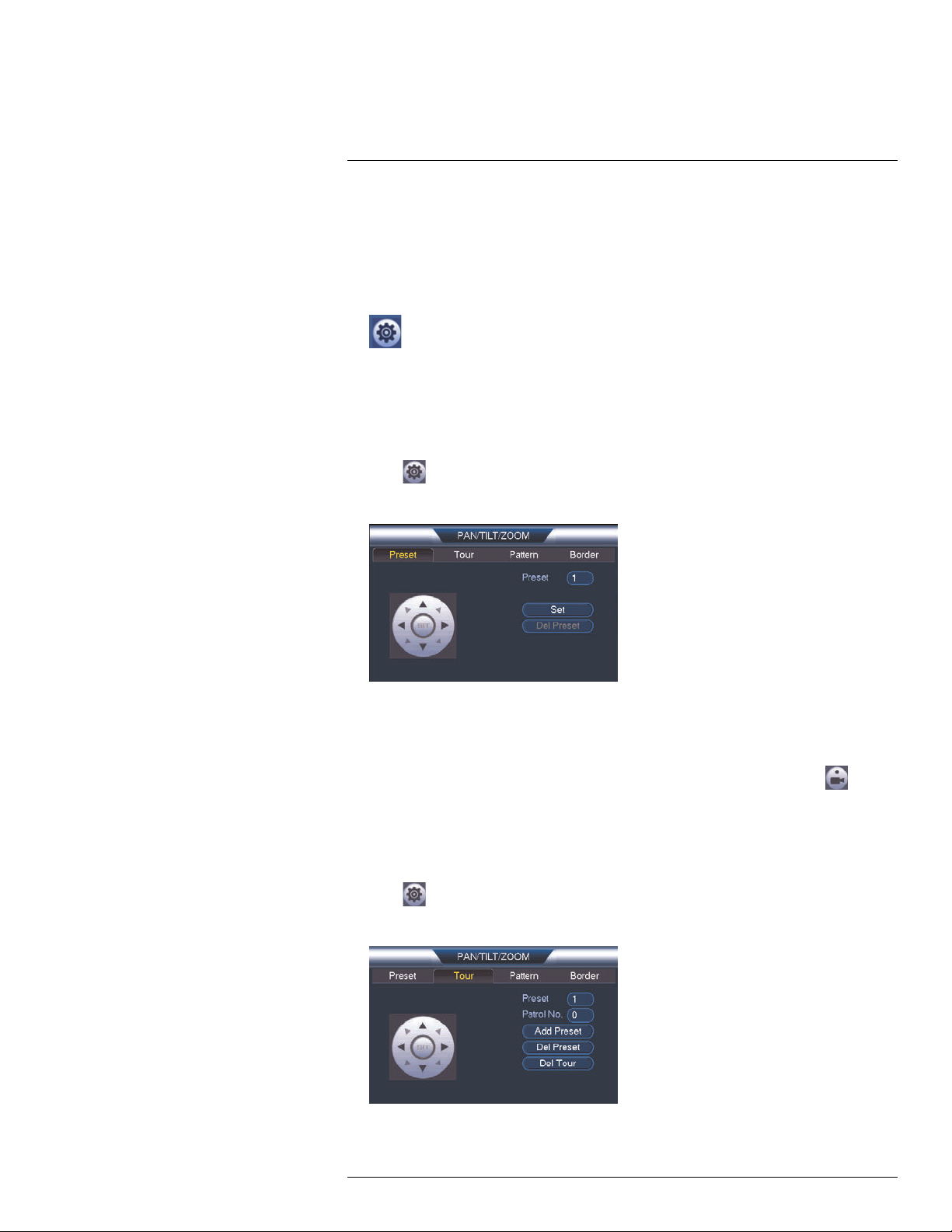
5.2.1 Presets
Presets will save a camera position for quick retrieval.
To add presets:
1. Click
to open the PAN/TILT/ZOOM menu.
2. Click the Preset tab.
3. Enter the number of the preset you want to create under Preset.
4. Move the camera to the desired position and click Set.
To go to a preset:
• Under No., select the number of the preset you would like to go to and click
.
5.2.2 Tours
Tours will cycle through a set of presets.
To create a tour:
1. Click
to open the PAN/TILT/ZOOM menu.
2. Click the Tour tab.
3. Under Patrol No., select the tour you would like to configure.
#LX400020; r.35429/35429; en-US
15
Page 19
5
Controlling the PTZ Camera with an NVR
4. Under Preset, select a preset you would like to add to the tour.
5. Click Add Preset.
6. Repeat steps 4 and 5 to add additional presets to the tour.
NOTE
Click Del Tour to clear all presets from a tour.
To run a tour:
• Under No., select the number of the tour you would like to go to and click
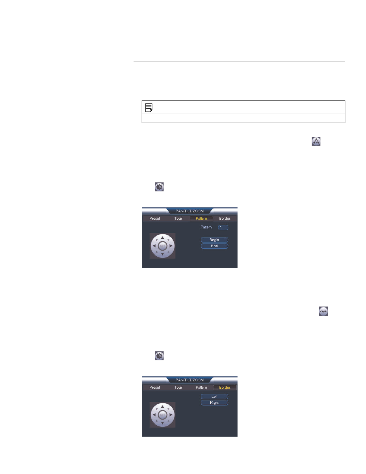
5.2.3 Pattern
Patterns automatically cycle the camera between two positions.
To create a pattern:
1. Click
to open the PAN/TILT/ZOOM menu.
2. Click the Pattern tab.
3. Under Pattern, enter the pattern you would like to configure.
4. Move the camera into the desired start position and click Begin.
5. Move the camera into the desired end position and click End.
To run a pattern:
• Under No., select the number of the pattern you would like to go to and click
.
.
5.2.4 Auto Scan
An auto scan automatically cycles between a left and right point.
To create a new auto scan:
1. Click
to open the PAN/TILT/ZOOM menu.
2. Click the Border tab.
#LX400020; r.35429/35429; en-US
16
Page 20

5
Controlling the PTZ Camera with an NVR
3. Move the camera into the desired left position and click Left.
4. Move the camera into the desired right position and click Right.
To run an auto scan:
• Click
.
#LX400020; r.35429/35429; en-US
17
Page 21
6
Technical Specifications
Image Sensor 1/3", 2.1MP CMOS (LNZ32P12)
1/2.7", 2.1MP CMOS (LNZ32P12S)
Video Format NTSC / PAL
Effective Pixels 1920 (H) x 1080 (V)
Resolution Up to 1080p
Range 360° Pan (Endless); 0–90° Tilt (Auto-Flip)
Pan/Tilt Speed Max 300°/Sec Pan; Max 200°/Sec Tilt.
Zoom
Min. Illumination
Lens / Lens Type Auto Focus / 5.1 – 61.2mm F1.6 – F2.3
Field of View (Horizontal) 4° ~ 51° (LNZ32P12)
Scan System Progressive
Synchronization Internal
Iris Auto Iris
S / N Ratio >55dB (AGC Off)
Termination RJ45 10 M / 100M Ethernet
Power Requirement PoE+ (Power over Ethernet, Class 4)
Power Consumption Max. 750mA
Operating Temperature Range 14°F ~ 140°F / -10°C ~ 60°C (LNZ32P12)
Operating Humidity Range
Indoor/Outdoor Both (IP66)
Weight (Camera Alone)
Weight (Camera & Wall Mount)
12x Optical Zoom & 16x Digital Zoom
0.05 Lux in Color; 0.005 Lux in Black and White
5° ~ 60° (LNZ32P12S)
-22°F ~ 140°F / -30°C ~ 60°C (LNZ32P12S)
Within 90%RH
2
4.0lbs / 1.8kg
5.7lbs / 2.6kg
1
; 24V AC
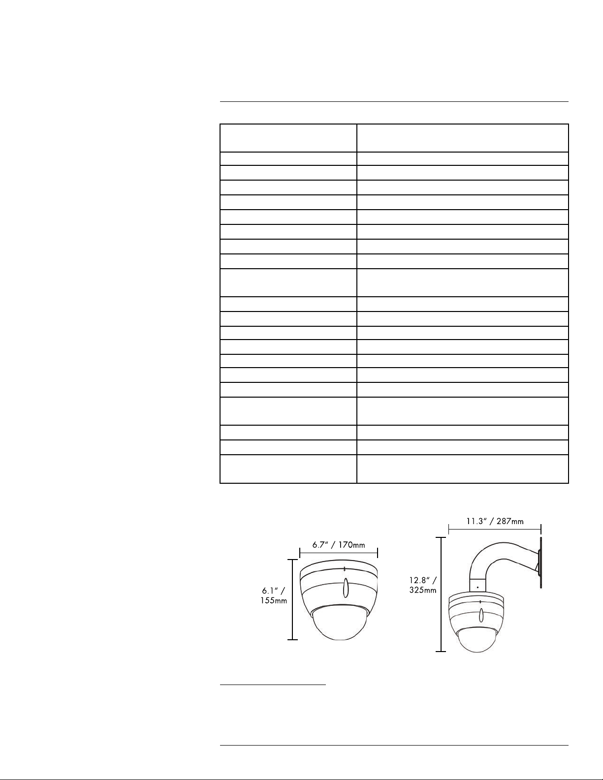
6.1 Dimensions
1. Compatible with all Lorex HD NVRs except for LNR200 & LNR300 Series.
2. Not intended for submersion in water. Installation in a sheltered location recommended.
#LX400020; r.35429/35429; en-US
18
Page 22

7
Troubleshooting
There is no picture at night.
• Camera is capable of seeing in extremely low light conditions (0.05 Lux), but it cannot
see in total darkness. It is recommended to install the camera where there is some ambient light (e.g. street lighting, starlight, moonlight, etc.) or leave a light on in the area
where the camera is installed.
No image at startup.
• The camera may take up to 1 minute to power up after being connected to the NVR.
Wait 2 minutes before following steps below.
• Check to ensure your camera is properly connected (see 3 Connecting the Camera,
page 3).
• If you are using a PoE switch, it must be PoE+ rated (PoE class 4). Standard PoE
switches are not adequate to power the camera. PoE+ switches are available for purchase on www.lorextechnology.com (model #: ACCLPS241B).
• If you are not using PoE+, you must connect the camera to the included 24V AC power
adapter. Do not use other power adapters with this product, as this will void the
warranty.
• Ensure the camera is connected to a router on the same network as the NVR.
• If the camera is connected to the LAN, you must search your network for cameras using
the NVR. See your NVR’s instruction manual for details.
• Make sure that the cable run is within the limitations specified in 3 Connecting the Cam-
era, page 3. All Ethernet cables must be rated CAT5e or higher.
• If using the power adapter, connect the power adapter to a different outlet.
• Ethernet cable may be damaged or not connected properly. Check your cable run or try
a different cable.
• Reset the camera to factory default settings. See 8 Resetting the Camera, page 20 for
details
No image or camera image is unclear.
• Dome cover is dirty. Clean the dome cover with a soft, slightly damp cloth. Do not use
anything other than water to clean the dome cover, as chemicals such as acetone can
permanently damage the plastic.
Image is distorted.
• Image may become unclear when camera is tilted too close to the camera base (e.g.
pointed parallel to the ceiling). Tilt the camera using NVR or FLIR Cloud™ Client PTZ
controls.
Image is too bright.
• Ensure your camera isn’t pointed directly at a source of light (e.g. sun or spot light).
• Check your NVR’s brightness and contrast settings.
• Move your camera to a different location.
Image is too dark.
• Check your NVR’s brightness and contrast settings.
• Move your camera to a different location.
NVR motion detection is constantly triggering.
• Turn off motion detection on the channel the PTZ camera is connected to. NVRs use
video motion detection, which means they detect motion by looking for changes between frames (images) in the video. If the camera is moving, the NVR will detect this as
motion.
#LX400020; r.35429/35429; en-US
19
Page 23
8
Resetting the Camera
The camera features a hard reset button that is used to reset all camera settings back to
their default values. This is useful in case you want to revert camera image settings back
to their default values.
To reset the camera:
1. Connect the camera as detailed in 3 Connecting the Camera. Make sure the camera is
powered on.
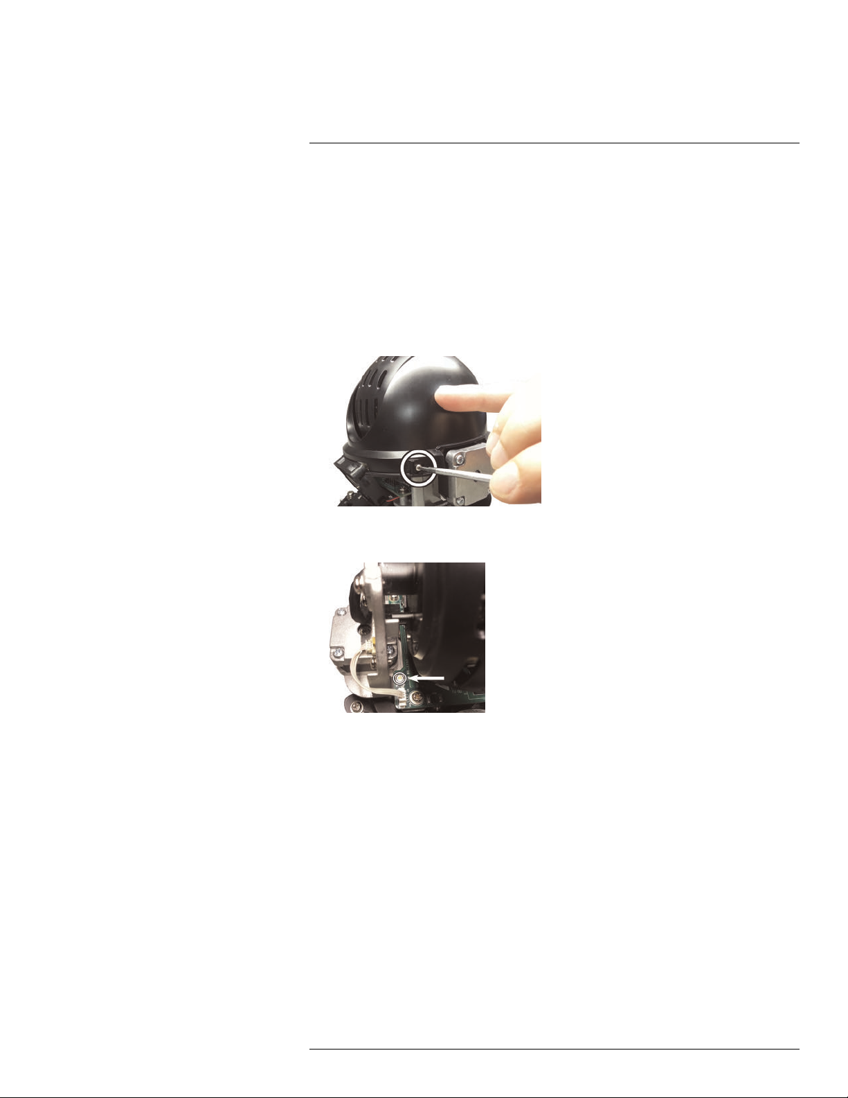
2. Use the included Allen key to loosen the dome cover screws (x3). Remove the dome
cover.
3. Use a Phillips screwdriver (not included) to remove the camera module cover screws
(x2). Lift the black camera module cover off of the camera.
4. Press and hold the reset button below the camera module for at least 10 seconds to
reset the camera to default settings.
#LX400020; r.35429/35429; en-US
20
Page 24

Website
last page
www.lorextechnology.com
Copyright
© 2016, Lorex Corporation
All rights reserved worldwide. Names and marks appearing herein are either registered trademarks or trademarks of Lorex Corporation and/or its subsidiaries. All
other trademarks, trade names or company names referenced herein are used for identification only and are the property of their respective owners.
Legal disclaimer
As our product is subject to continuous improvement, Lorex Corporation & subsidiaries reserve the right to modify product design, specifications & prices without
notice and without incurring any obligation.E&OE.
Publ. No.: LX400020
Commit:
Head: 35429
Language: en-US
Modified: 2016-05-06
Formatted: 2016-05-06
35429
Page 25

Manuel d’utilisation
Série de caméras réseau
PTZ LNZ32P12 12X
Page 26

Merci d’avoir acheté ce produit. Lorex Corporation s’engage à fournir à nos clients une solution de
sécurité fiable et de haute qualité.
Ce manuel fait référence au modèle suivant :
LNZ32P12
LNZ32P12S
Pour consulter en ligne le plus récent manuel, les téléchargements et les mises à jour du produit, et pour
en savoir plus sur notre gamme complète d’accessoires, visitez notre site Web au :
www.lorextechnology.com
AVERTISSEMENT
RISQUE D’ÉLECTROCUTION
NE PAS OUVRIR
AVERTISSEMENT : NE PAS RETIRER LE COUVERCLE AFIN DE RÉDUIRE LE
RISQUE DE DÉCHARGES ÉLECTRIQUES. AUCUNE PIÈCE INTERNE NE
NÉCESSITE D’ENTRETIEN.
SE RÉFÉRER À UN TECHNICIEN QUALIFIÉ.
Le symbole de l’éclair fléché dans un triangle équilatéral est destiné
à alerter l’utilisateur de la présence d’une « tension dangereuse »
non isolée dans le boîtier du produit pouvant être d’amplitude
suffisante pour constituer un risque de décharge électrique.
Le point d’exclamation dans un triangle équilatéral est destiné à
alerter l’utilisateur de la présence d’importantes instructions
d’utilisation et de maintenance (entretien) dans la documentation qui
accompagne l’appareil.
AVERTISSEMENT : POUR PRÉVENIR TOUT RISQUE D’INCENDIE OU
D’ÉLECTROCUTION, N’EXPOSEZ PAS CETAPPAREIL À LA PLUIE OU L’HUMIDITÉ.
MISE EN GARDE : POUR ÉVITER LES DÉCHARGES ÉLECTRIQUES, JUMELEZ LA
LAME LARGE DE LA FICHE À LA FENTE LARGE ET INSÉREZ COMPLÈTEMENT.
#LX400020; r. 2.0/35424/35424; fr-CA
iv
Page 27

Tables des matières
1 Mesures de sécurité ............................................................................1
2 Mise en route...................................................................................... 2
3 Brancher la caméra .............................................................................3
3.1 Option 1 : Branchement de la caméra à un NVR................................ 3
3.2 Connexion des caméras au réseau local (LAN) .................................3
4 Installation .........................................................................................7
4.1 Conseils et avertissements d’installation ..........................................7
4.2 Installation (intérieur/extérieur)....................................................... 7
5 Contrôle de la caméra PTZ avec un NVR............................................... 13
5.1 Contrôle d’une caméra PTZ (NVR local) ........................................ 13
5.2 Commandes avancées PTZ ........................................................ 14
5.2.1 préréglages .................................................................. 15
5.2.2 Visites guidées .............................................................. 15
5.2.3 Motif............................................................................ 16
5.2.4 Balayage automatique..................................................... 16
6 Spécifications techniques .................................................................. 18
6.1 Dimensions ............................................................................. 18
7 Dépannage ....................................................................................... 19
8 Réinitialisation de la caméra............................................................... 21
#LX400020; r. 2.0/35424/35424; fr-CA
v
Page 28

1
Mesures de sécurité
• Lire attentivement ce guide et le garder pour consultation ultérieure
• Suivre toutes les instructions pour une bonne utilisation et manipuler avec attention
• Utiliser la caméra à la température spécifiée, au taux d’humidité et au niveau de tension
affiché dans les spécifications techniques.
• La caméra est conçue pour un usage extérieur et est résistante aux intempéries lors-
qu’elle est bien installée. La caméra n’est pas conçue pour être immergée dans l’eau.
L’installation est recommandée dans un endroit couvert.
• Ne pas démonter la caméra.
• Ne pas pointer votre caméra vers le soleil ou une source intense de lumière.
• Utiliser seulement l’alimentation régulée fournie. L’utilisation d’une alimentation non ré-
gulée et non conforme peut endommager ce produit et annuler la garantie.
• S’assurer d’installer la caméra dans un endroit pouvant supporter le poids de la camé-
ra. Si l’appareil est installé sur une surface de plaques de plâtre, vous devez visser au
moins deux des vis de montage à travers un montant de bois. Consulter 4.2 Installation
(intérieur/extérieur), page 7 afin d’obtenir les directives d’installation complètes.
• S’assurer qu’il n’y ait pas de câbles électriques sous tension à l’endroit où vous pré-
voyez fixer la caméra.
• Un nettoyage périodique peut s’avérer nécessaire. Utiliser un linge humide seulement.
Ne pas utiliser autre chose que de l’eau pour nettoyer le couvercle du dôme, étant
donné que les produits chimiques tels que l’acétone peuvent endommager le plastique
de manière permanente.
#LX400020; r. 2.0/35424/35424; fr-CA
1
Page 29

2
Mise en route
Le système est livré avec les éléments suivants :
Caméra PTZ
100 pi (30,5 m) Cat5e UL
Câble de rallonge Ethernet
conforme
Anneaux d’attache x 4 Boulons Allen x 4 Clé Allen
Support mural Montage suspendu
Bloc d’alimentation
Vis de montage
et ancrages
Modèle d’assemblage
#LX400020; r. 2.0/35424/35424; fr-CA
Manuel d’utilisation
2
Page 30

3
Brancher la caméra
REMARQUE
Il est recommandé de brancher la caméra à votre NVR et de tester les contrôles PTZ avant l’installation
permanente. Pour plus d’informations sur la configuration des commandes PTZ, voir 5 Contrôle de la ca-
méra PTZ avec un NVR, page 13.
3.1 Option 1 : Branchement de la caméra à un NVR
1. Brancher le connecteur PoE+ sur le câble de caméra au câble de rallonge Ethernet
inclus.
2. Brancher le câble de rallonge Ethernet à l’un des ports PoE+ sur le panneau arrière de
votre NVR.
REMARQUE
Vous pouvez utiliser un câble Ethernet certifié CAT5e jusqu’à 300 pi (91 m) pour brancher la caméra à votre NVR. La caméra est Compatible avec toute la série Lorex HD NVR sauf pour les séries LNR200 et LNR300. Pour consulter la liste la plus récente des enregistreurs compatibles, visitez le
www.lorextechnology.com/support.
3.2 Connexion des caméras au réseau local (LAN)
Pour plus de flexibilité, vous pouvez également connecter la caméra au même réseau local (LAN) que le NVR. C’est réalisé en connectant la caméra au même routeur que le
NVR. Pour ces installations, un commutateur externe PoE (vendu séparément) ou un
adaptateur d’alimentation (inclus) doit être utilisé pour procurer du courant à la caméra.
Vous devez aussi ajouter la caméra sur le NVR avant qu’elle montre une image sur le moniteur ou qu’elle soit enregistrée par le NVR.
Qu’est ce que PoE+?
PoE (Power over Ethernet) est une technologie qui permet aux câbles Ethernet d’amener
l’alimentation aux dispositifs branchés. Les dispositifs de haute puissance tels que les caméras PTZ utilisent PoE+ (également connu sous le nom de PoE catégorie 4 ou
IEEE 802.3at), qui fournit plus de puissance aux dispositifs connectés que le PoE standard. Les NVR compatibles utilisent les ports PoE+ pour fournir l’alimentation et les
commandes PTZ à la caméra, ainsi que les connexions vidéos au NVR. Les ports PoE+
fourniront jusqu’à 30W à chaque dispositif connecté, tandis que les ports PoE standard
(catégorie 3) peuvent seulement fournir jusqu’à 15W. Afin d’utiliser cette caméra certifiée
PoE+ sans l’adaptateur d’alimentation fourni, vous devez le connecter directement à un
NVR compatible (Compatible avec toute la série Lorex HD NVR sauf pour les séries LNR200 et LNR300. Pour consulter la liste la plus récente des enregistreurs compatibles, visitez le www.lorextechnology.com/support) ou un commutateur PoE+ sur le même
réseau que le NVR. Les commutateurs PoE+ sont offerts sur www.lorextechnology.com
(nº de modèle : ACCLPS241B).
Procéder comme suit pour connecter la caméra au NVR par le réseau LAN.
#LX400020; r. 2.0/35424/35424; fr-CA
3
Page 31

3
Brancher la caméra
Étape 1 de 2 --- Option A : Connexion de la caméra à votre réseau local en utilisant
un commutateur PoE+ facultatif :
1. Brancher un câble Ethernet certifié CAT5e jusqu’à 300 pi (91 m) ou supérieur (non inclus) de votre port LAN sur un commutateur externe PoE+ (vendu séparément sur
www.lorextechnology.com) à votre routeur. Brancher le câble d’alimentation au
commutateur PoE et dans une prise de courant ou un parasurtenseur.
REMARQUE
La terminologie peut varier selon le modèle de commutateur PoE+ que vous utilisez.
2. Brancher la caméra au commutateur PoE+ à l’aide du câble Ethernet inclus (ou un
câble Ethernet CAT5e jusqu’à 300 pi (91 m)). Le commutateur PoE+ peut procurer l’alimentation et la transmission vidéo de la même manière que votre NVR.
#LX400020; r. 2.0/35424/35424; fr-CA
4
Page 32

3
Brancher la caméra
Étape 1 de 2 --- Option B : Connexion de la caméra à votre réseau local en utilisant
les adaptateurs d’alimentation :
1. Brancher le bloc d’alimentation inclus à la caméra.
2. Brancher la caméra à un routeur dans le même réseau que le NVR en utilisant le câble
Ethernet inclus (ou un câble Ethernet certifié CAT5e jusqu’à 300 pi (91 m) ou
supérieur).
Étape 2 de 2 : Ajout de la caméra au NVR :
1. Cliquer à droite et sélectionner Rechercher un appareil.
2. Se connecter avec le compte d’administrateur (nom d’utilisateur par défaut : admin;
mot de passe par défaut : 000000).
3. Cliquer sur Recherche dispositif. Le système cherche les caméras prises en charge
sur le réseau.
4. Cocher la/les caméra(s) que vous souhaitez ajouter.
#LX400020; r. 2.0/35424/35424; fr-CA
5
Page 33

3
Brancher la caméra
5. Cliquer sur Ajouter. L’indicateur de statut devient vert si la caméra est bien connectée.
6. Cliquer sur OK pour sauvegarder les changements.
REMARQUE
Vous pouvez aussi ajouter une caméra à un canal spécifique en passant la souris sur un canal vide en
vue d’écran partagé et en cliquant sur
ter et cliquer avec le bouton droit de la souris pour sortir.
. Ensuite double-cliquer sur la caméra que vous voudriez ajou-
#LX400020; r. 2.0/35424/35424; fr-CA
6
Page 34

4
Installation
4.1 Conseils et avertissements d’installation
AVERTISSEMENT
S’assurer d’installer la caméra dans un endroit pouvant supporter le poids de la caméra. Si l’appareil est
installé sur une surface de cloison sèche, vous devez visser les deux vis de montage à travers un montant de bois. Consulter 4.2 Installation (intérieur/extérieur), page 7 afin d’obtenir les directives d’installation complètes.
• La caméra est conçue pour être utilisée à l’extérieur. Il est recommandé d’installer la
caméra dans un endroit couvert, par exemple sous l’avant-toit de la toiture.
• Il est recommandé d’installer la caméra aussi haut que possible pour obtenir la meil-
leure image possible.
• La caméra a la capacité de voir dans des conditions d’éclairage extrêmement faible
(0,05 Lux), mais ne peut pas voir dans l’obscurité totale. Il est recommandé d’installer
la caméra dans un lieu avec un peu de lumière ambiante (par ex. : éclairage de rue ou
lumière des étoiles, lumière de la lune, etc.) ou laisser un peu d’éclairage là où la caméra est installée.
• Fixer la caméra à un endroit où la lentille sera loin de la lumière du soleil directe et
intense.
• Planifier l’installation des câbles pour que cela n’interfère pas avec les lignes de cou-
rant ou les lignes téléphoniques.
• S’assurer de respecter le code du bâtiment local.
• S’assurer que le câble de la caméra ne soit pas exposé ou coupé facilement.
• Fixer la caméra dans un lieu visible, mais hors de portée.
REMARQUE
Cette caméra est conçue pour être fixée à un mur ou à un plafond.
4.2 Installation (intérieur/extérieur)
Pour installer la caméra au mur :
ATTENTION
S’assurer de débrancher l’alimentation avant d’installer la caméra. La caméra commence immédiatement
à bouger lorsque le bloc d’alimentation est branché.
1. Faire des marques pour les trous de vis de montage (4 x) et passer les câbles par le
support de fixation murale. Percer aux endroits marqués.
2. Tirer le câble Ethernet de votre NVR, commutateur PoE+ ou routeur à travers le trou situé dans la surface de montage.
#LX400020; r. 2.0/35424/35424; fr-CA
7
Page 35

Installation4
3. Passer le câble Ethernet à travers le support de la fixation murale. Fixer le support mural solidement au mur en utilisant les vis de montage fournies (4 x) et les ancrages inclus (4 x), si nécessaire.
AVERTISSEMENT
S’assurer d’installer le support mural à un endroit pouvant supporter le poids de la caméra. Si la ca-
méra est installée sur une surface de plaques de plâtre, vous devez visser au moins deux des vis de
montage à travers un montant de bois. Consulter le schéma ci-dessous pour obtenir plus de détails.
4. Retirer la pellicule de plastique des trous de vis de la partie inférieure de la caméra.
#LX400020; r. 2.0/35424/35424; fr-CA
8
Page 36

Installation4
5. Utiliser la clé Allen fournie pour dévisser les vis du couvercle du dôme (x3). Retirer le
couvercle du dôme.
6. Retirer la bague de mousse* autour du module de caméra.
7. Passer les câbles de la caméra par le trou du montage suspendu. Utiliser les boulons
Allen (x4) afin de fixer la base de la caméra PTZ solidement au montage suspendu.
Serrer fermement à l’aide de la clé Allen incluse.
#LX400020; r. 2.0/35424/35424; fr-CA
9
Page 37

Installation4
8. Remettre le couvercle en forme de dôme en s’assurant que le joint torique en caoutchouc autour de la base de la caméra est en place et que la flèche d’alignement* du
couvercle en dôme est vis-à-vis la base de la caméra.
9. Serrer fermement les vis du couvercle en dôme (3 x) à l’aide de la clé Allen incluse.
10. Desserrer la vis de sécurité* sur le support de montage mural.
11. Brancher la caméra au câblage dans le support de montage mural. Consulter 3 Bran-
cher la caméra, page 3 afin d’obtenir les directives d’installation complètes.
12. Tourner le montage suspendu sur le support de montage mural. Serrer fermement la
vis de sécurité* sur le support de montage mural.
13. Retirer le film de protection en vinyle du couvercle du dôme une fois l’installation
terminée.
#LX400020; r. 2.0/35424/35424; fr-CA
10
Page 38

Installation4
Pour installer la caméra au plafond :
ATTENTION
• S’assurer de débrancher l’alimentation avant d’installer la caméra. La caméra commence immédiatement à bouger lorsque le bloc d’alimentation est branché.
• S’assurer d’installer la caméra dans un endroit pouvant supporter le poids de la caméra.
1. Retirer la pellicule de plastique des trous de vis de la partie inférieure de la caméra.
2. Si nécessaire, utilisez le gabarit de montage (inclus) afin de marquer l’emplacement
des trous des vis de montage et des câbles. Percer aux endroits marqués.
REMARQUE
Si vous passez les câbles le long de la surface de montage, vous devez passer le câble dans l’encoche de câble sur la base de la caméra. Cela gardera la caméra à niveau sur la surface, lorsque
montée.
3. Utiliser la clé Allen fournie pour dévisser les vis du couvercle du dôme (x3). Retirer le
couvercle du dôme.
4. Retirer la bague de mousse* autour du module de caméra.
5. Brancher la caméra au câblage dans le plafond. Consulter 3 Brancher la caméra, page
3 afin d’obtenir les directives d’installation complètes.
#LX400020; r. 2.0/35424/35424; fr-CA
11
Page 39

Installation4
6. Enfoncer chaque joint torique inclus (x4) sur chacune des vis de montage incluses
(x4). Fixer la caméra PTZ fermement au plafond en utilisant les vis de montage incluses jusqu’à ce que les joints toriques soient à plat contre la base de la caméra. Utiliser
les ancrages si nécessaire.
7. Remettre le couvercle en forme de dôme en s’assurant que le joint torique en caoutchouc autour de la base de la caméra est en place et que la flèche d’alignement* du
couvercle en dôme est vis-à-vis la base de la caméra.
8. Serrer fermement les vis du couvercle en dôme à l’aide de la clé Allen incluse.
9. Retirer le film de protection en vinyle du couvercle du dôme une fois l’installation
terminée.
#LX400020; r. 2.0/35424/35424; fr-CA
12
Page 40

5
Contrôle de la caméra PTZ avec un NVR
La caméra peut accepter des commandes PTZ directement par le câble Ethernet. Il n’est
pas nécessaire de passer un câblage spécial pour contrôler le mouvement de la caméra
PTZ.
REMARQUE
Pour la liste la plus récente des NVR compatibles, veuillez consulter www.lorextechnology.com/support.
Pour connecter une caméra PTZ au système :
1. Connecter la caméra à votre NVR conformément à 3 Brancher la caméra, page 3.
2. Cliquer sur le bouton droit, puis cliquer sur Main Menu. Saisir le nom d’utilisateur du
système (par défaut : admin) et le mot de passe (par défaut : 000000) si demandé.
3. Cliquer
4. Sous Channel, sélectionner le canal où sera branchée votre caméra PTZ.
5. Sous PTZ Type, sélectionner Remote.
6. Cliquer sur OK. Vous pouvez maintenant contrôler votre caméra PTZ en utilisant le
système.
5.1 Contrôle d’une caméra PTZ (NVR local)
1. Dans Vue en direct, double cliquer sur le canal auquel une caméra PTZ est connectée
pour l’ouvrir en mode plein écran.
2. Cliquer avec le bouton droit de la souris et cliquer PTZ. Si demandé, entrez le nom d’utilisateur et le mot de passe du système. Le menu PTZ s’ouvre.
3. Utiliser les contrôles PTZ à l’écran pour contrôler la caméra.
>Setting>Pan/Tilt/Zoom.
#LX400020; r. 2.0/35424/35424; fr-CA
13
Page 41

5
Contrôle de la caméra PTZ avec un NVR
Contrôles PTZ
1. Touches de navigation: Cliquer pour faire tourner et basculer la caméra. Cliquer sur
SIT pour arrêter l’activité actuelle.
2. Souris PTZ: Cliquer pour activer le mode souris PTZ. En mode souris PTZ :
• Cliquer-glisser pour contrôler la caméra.
• Utiliser la roulette de défilement afin de faire un zoom avant et arrière.
• Cliquer à droite pour sortir et retourner aux contrôles PTZ normaux.
3. Zoom/Mise au point/Iris: Cliquer sur +/- afin d’ajuster le zoom, la mise au point et
l’iris.
4. Contrôles avancés: Appuyer pour ouvrir les contrôles PTZ avancés.
5. Vitesse: Entrer une vitesse PTZ entre 1 (plus lent) et 8 (plus rapide).
5.2 Commandes avancées PTZ
Les contrôles PTZ avancés peuvent être utilisés pour sauvegarder des positions de la caméra et pour passer entre diverses positions de caméra, ainsi que pour automatiser les
actions de la caméra.
Pour ouvrir les contrôles PTZ avancés :
• Cliquer sur la flèche dans la fenêtre de contrôle PTZ afin d’ouvrir les contrôles avancés.
Aperçu des contrôles PTZ avancés :
1. Numéro : Sélectionner le nombre d’actions que vous désirez réaliser.
2. Non compatible.
#LX400020; r. 2.0/35424/35424; fr-CA
14
Page 42

5
Contrôle de la caméra PTZ avec un NVR
3. Menu caméra PTZ: Cliquer pour ouvrir le menu à l’écran de la caméra. Ce menu
concerne seulement les utilisateurs avancés
4. Prérégler : Cliquer pour activer le préréglage sélectionné.
5. Autopanoramique : Cliquer pour démarrer un panoramique. Pendant le panoramique
automatique, la caméra tournera sans arrêt sur 360°.
6. Tournée : Cliquer pour démarrer la visite guidée sélectionnée.
7. Non pris en charge.
8. Modèle : Cliquer pour exécuter le motif sélectionné.
9. Non compatible
10. Balayage automatique : Cliquer pour exécuter l’autobalayage sélectionné.
11.
: Cliquer pour ouvrir le menu PAN/TILT/ZOOM , où il est possible de configurer
les préréglages, les tournées, les modèles et les balayages automatiques.
5.2.1 préréglages
Les préréglages sauvegarderont la position de la caméra pour pouvoir y revenir
rapidement.
Pour ajouter des préréglages :
1. Cliquer
pour ouvrir le menu PAN/TILT/ZOOM
2. Cliquer sur l’onglet Préréglages.
3. Saisir le numéro du préréglage que vous voulez créer sous Préréglage.
4. Déplacez la caméra vers la position désirée et cliquer sur Régler.
Pour accéder à un préréglage :
• Sous Nº sélectionnez le numéro du préréglage auquel vous voulez accéder, puis cli-
quer sur
.
5.2.2 Visites guidées
Les visites guidées passeront par un ensemble de préréglages.
Pour créer une visite guidée :
1. Cliquer
#LX400020; r. 2.0/35424/35424; fr-CA
pour ouvrir le menu PAN/TILT/ZOOM
15
Page 43

5
Contrôle de la caméra PTZ avec un NVR
2. cliquer sur l’ongletTournée.
3. Sous Nº de patrouille, sélectionnez la tournée que vous voulez configurer.
4. Sous Préréglages, sélectionnez un préréglage que vous voulez ajouter à la tournée.
5. Cliquer sur Ajoutez préréglage.
6. Répétez les étapes 4 et 5 afin d’ajouter d’autres préréglages à la tournée.
REMARQUE
Cliquer sur Supprimer tournée pour éliminer tous les préréglages d’une tournée.
Pour effectuer une visite guidée :
• Sous Nº, sélectionnez le numéro de la tournée à laquelle vous voulez accéder et Cli-
quer sur
.
5.2.3 Motif
Les motifs font automatiquement fluctuer la caméra entre deux positions.
Pour créer un motif :
1. Cliquer
pour ouvrir le menu PAN/TILT/ZOOM
2. Cliquer sur l’onglet Modèle.
3. Sous Modèles, saisissez le modèle que vous voulez configurer.
4. Déplacez la caméra vers la position initiale désirée, puis Cliquer sur Début.
5. Déplacez la caméra vers la position finale désirée, puis Cliquer sur Fin.
Pour exécuter un motif :
• Sous Nº, sélectionnez le numéro du modèle auquel vous voulez accéder, puis Cliquer
sur
.
5.2.4 Balayage automatique
Un balayage automatique réalise automatiquement un balayage de gauche à droite.
#LX400020; r. 2.0/35424/35424; fr-CA
16
Page 44

5
Contrôle de la caméra PTZ avec un NVR
Pour créer un nouveau balayage automatique :
1. Cliquer
pour ouvrir le menu PAN/TILT/ZOOM
2. Cliquer sur l’onglet Frontières.
3. Déplacez la caméra vers la gauche à la position désirée, puis Cliquer sur Gauche.
4. Déplacez la caméra vers la droite à la position désirée, puis Cliquer sur Droite.
Pour démarrer un balayage automatique :
• Cliquer sur
.
#LX400020; r. 2.0/35424/35424; fr-CA
17
Page 45

6
Spécifications techniques
Capteur d’images 1/3 po CMOS 2,1 MP (LNZ32P12)
1/2,7 po CMOS 2,1 MP (LNZ32P12S)
Format vidéo NTSC / PAL
Pixels effectifs 1920 (H) x 1080 (V)
Résolution Jusqu’à 1080 p
de fonctionnement Vue panoramique à 360 ° (infini); inclinaison de 0 à 90 ° (ren-
Vue panoramique/vitesse d’inclinaison Max 300 °/sec (pan); max 200 °/sec (inclinaison)
Zoom Zoom optique 12 x et zoom numérique 16 x
Illumination min. 0,05 Lux en couleur; 0,005 Lux en noir et blanc
Lentille et type de lentille Mise au point automatique / 5,1 – 61,2 mm F1.6 – F2.3
Champ de vision (horizontal) 4° ~ 51° (LNZ32P12)
Système de balayage Progressif
Synchronisation
Iris Diaphragme automatique
Rapport S/B >55 dB (CAG désactivé)
Connecteur Câble Ethernet RJ45 10M/100M
Tension requise PoE+ (alimentation Ethernet, classe 4)
Consommation d’électricité
Plage de température de
fonctionnement
Taux d’humidité de fonctionnement Dans les limites de 90 % d’humidité relative
Intérieur/extérieur Les deux (IP66)
Poids (caméra)
Poids (caméra et montage mural)
versement automatique)
5° ~ 60° (LNZ32P12S)
Interne
1
, 24 V c.a.
Max. 750mA
14°F ~ 140°F/-10°C ~ 60°C (LNZ32P12)
-22°F ~ 140°F/-30°C ~ 60°C (LNZ32P12S)
2
4,0 lb/1,8 kg
5,7 lb/2,6 kg
6.1 Dimensions
1. Compatible avec toute la série Lorex HD NVR sauf pour les séries LNR 200 et LNR 300.
2. Ne pas immerger dans l’eau. Installation recommandée dans un emplacement couvert.
#LX400020; r. 2.0/35424/35424; fr-CA
18
Page 46

7
Dépannage
Il n’y a pas d’image la nuit.
• La caméra a la capacité de voir dans des conditions d’éclairage extrêmement faible
(0,05 Lux), mais ne peut pas voir dans l’obscurité totale. Il est recommandé d’installer
la caméra dans un lieu avec un peu de lumière ambiante (par ex : éclairage de rue, lumière des étoiles, lumière de la lune, etc.) ou laisser une lumière allumée là où la caméra est installée.
Pas d’image au démarrage.
• L’allumage de la caméra peut prendre jusqu’à une minute après avoir connecté celle-ci
au NVR. Attendre 2 minutes avant d’effectuer les étapes ci-dessous.
• Vérifier que la caméra est correctement connectée (voir 3 Brancher la caméra, page 3).
• Si vous utilisez un commutateur PoE, il doit être certifié PoE+ (PoE catégorie 4). Les
commutateurs PoE standard ne sont pas appropriés pour alimenter la caméra. Les
commutateurs PoE+ sont disponibles à l’achat sur www.lorextechnology.com (n° de
modèle : ACCLPS241B).
• Si vous n’utilisez pas PoE+, vous devez connecter la caméra sur l’adaptateur d’alimen-
tation 24V c.a. inclus. Ne pas utiliser d’autres blocs d’alimentation avec ce produit, cela
annulerait la garantie.
• S’assurer que la caméra est connectée à un routeur sur le même réseau que le NVR.
• Si la caméra est connectée au LAN, vous devez rechercher dans votre réseau les ca-
méras qui utilisent le NVR. Voir le manuel d’instruction de votre NVR pour plus de
renseignements.
• S’assurer que le câble est dans les limites spécifiées dans 3 Brancher la caméra, page
3 Tous les câbles Ethernet doivent être certifiés CAT5e ou supérieur.
• Si vous utilisez l’adaptateur d’alimentation, brancher l’adaptateur d’alimentation sur
une prise différente.
• Le câble Ethernet est peut-être endommagé ou n’est pas connecté correctement. Véri-
fier votre câble ou essayer un autre câble.
• Restaurer les paramètres par défaut de la caméra. Consulter 8 Réinitialisation de la ca-
méra, page 21 pour plus de détails.
Pas d’image ou une image trouble de la caméra.
• Le couvercle du dôme est sale. Nettoyez le couvercle du dôme avec un tissu doux et lé-
gèrement humide. Ne pas utiliser autre chose que de l’eau pour nettoyer le couvercle
du dôme, étant donné que les produits chimiques tels que l’acétone peuvent endommager le plastique de manière permanente.
L’image est déformée.
• L’image peut devenir trouble quand la caméra est inclinée trop près de la base de la ca-
méra (par ex : pointée parallèlement au plafond). Incliner la caméra en utilisant les
contrôles Client FLIR Cloud™ PTZ ou NVR.
L’image est trop claire.
• S’assurer que votre caméra ne pointe pas vers une source lumineuse (p. ex. soleil,
projecteur).
• Vérifier les paramètres de luminosité et de contraste du NVR
• Pointer votre caméra à un autre endroit.
L’image est trop sombre.
• Vérifier les paramètres de luminosité et de contraste du NVR
• Pointer votre caméra à un autre endroit.
La détection de mouvement du NVR est constamment déclenchée.
#LX400020; r. 2.0/35424/35424; fr-CA
19
Page 47

7
Dépannage
• Éteindre le détecteur de mouvement sur le canal où la caméra PTZ est connectée. Les
NVR utilisent la détection de mouvement vidéo, ce qui veut dire qu’ils détectent les
mouvements en cherchant des changements entre chaque image par seconde (images) de la vidéo. Si la caméra est en mouvement, le NVR détectera cela comme un
mouvement.
#LX400020; r. 2.0/35424/35424; fr-CA
20
Page 48

8
Réinitialisation de la caméra
La caméra est équipée d’un bouton de réinitialisation qui permet de réinitialiser tous les
paramètres de la caméra, afin de revenir aux valeurs par défaut. Ceci est utile pour rétablir
les réglages d’image de la caméra aux valeurs par défaut.
Pour réinitialiser la caméra :
1. Brancher la caméra comme indiqué sur 3 Brancher la caméra. S’assurer que la caméra est allumée.
2. Utiliser la clé Allen fournie pour dévisser les vis du couvercle du dôme (x3). Retirer le
couvercle du dôme.
3. Utiliser un tournevis Phillips (non inclus) pour retirer le module de la caméra vis de
couvercle (x2). Soulever le couvercle noir du module de la caméra hors de la caméra.
4. Appuyer et maintenir enfoncé le bouton de réinitialisation sous le module de caméra
pendant au moins 10 sec. afin de réinitialiser la caméra aux paramètres par défaut.
#LX400020; r. 2.0/35424/35424; fr-CA
21
Page 49

Site Web
last page
www.lorextechnology.com
Droits dauteur
© 2016, Lorex Corporation
Tous droits réservés dans le monde entier. Les noms et les marques figurant sur ce site Web sont des marques déposées ou des marques commerciales de Lorex
Corporation et/ou de ses filiales. Toutes les autres marques, et tous les autres noms commerciaux ou noms de société mentionnés dans ce site Web sont utilisé(e)s
pour les seules fins didentification et sont la propriété de leurs propriétaires respectifs.
Mentions légales
Étant donné que notre produit est soumis à une amélioration continue, Lorex Corporation et ses filiales se réservent le droit de modifier la conception, les
spécifications et les prix de ce produit sans préavis et sans encourir aucune obligation. E&OE.
Publ. No.: LX400020
Release: 2.0
Commit:
Head: 35424
Language: fr-CA
Modified: 2016-05-04
Formatted: 2016-05-04
35424
Page 50

Manual de instrucciones
Serie de cámaras PTZ de
red de 12X LNZ32P12
Page 51

Gracias por adquirir este producto. Lorex Corporation está comprometido a proporcionar a nuestros
clientes una solución de seguridad de alta calidad y confiable.
Este manual se refiere al siguiente modelo:
LNZ32P12
LNZ32P12S
Para obtener el último manual en línea, descargas y actualizaciones de productos, y para aprender sobre
nuestra línea completa de accesorios, visite nuestro sitio web en:
www.lorextechnology.com
ADVERTENCIA
RIESGO DE CHOQUE
ELÉCTRICO
NO ABRIR
ADVERTENCIA: PARA REDUCIR EL RIESGO DE DESCARGA ELÉCTRICA, NO
QUITE LA TAPA. NO CONTIENE PARTES SUJETAS A MANTENIMIENTO.
EL SERVICIO DE MANTENIMIENTO DEBE ESTAR A CARGO DE PERSONAL
CALIFICADO.
El símbolo del rayo con la punta en flecha dentro de un triángulo
equilátero pretende alertar al usuario sobre la presencia de un
"voltaje peligroso" sin aislación dentro de la carcasa del producto,
que puede ser de tal magnitud que suponga un riesgo de choque
eléctrico.
El signo de exclamación dentro de un triángulo equilátero pretende
alertar al usuario sobre la presencia de instrucciones de
mantenimiento (servicio) y operación importantes en la literatura que
acompaña al dispositivo.
ADVERTENCIA: PARA EVITAR EL PELIGRO DE INCENDIO O CHOQUE, NO
EXPONGA ESTA UNIDAD A LA LLUVIA O LA HUMEDAD.
PRECAUCIÓN: PARA EVITAR CHOQUES ELÉCTRICOS, CONECTE LA PATA
ANCHA DEL ENCHUFE A LA RANURA ANCHA E INSÉRTELA COMPLETAMENTE.
#LX400020; r. 2.0/35425/35425; es-MX
iv
Page 52

Tabla de contenido
1 Instrucciones de seguridad ..................................................................1
2 Instrucciones iniciales .........................................................................2
3 Cómo conectar la cámara.....................................................................3
3.1 Opción 1: Conexión de la cámara a un NVR .....................................3
3.2 Conexión de cámaras a la red de área local (LAN) .............................3
4 Instalación..........................................................................................7
4.1 Consejos y advertencias de instalación ...........................................7
4.2 Instalación (interiores/exteriores).................................................... 7
5 Control de la cámara PTZ con una NVR ................................................ 13
5.1 Control de una cámara PTZ (NVR local) ........................................ 13
5.2 Controles de PTZ avanzados ...................................................... 14
5.2.1 Predefiniciones.............................................................. 15
5.2.2 Recorridos.................................................................... 15
5.2.3 Patrón.......................................................................... 16
5.2.4 Lector automático .......................................................... 16
6 Especificaciones técnicas .................................................................. 18
6.1 Dimensiones............................................................................ 18
7 Resolución de problemas ................................................................... 19
8 Cómo restablecer la cámara ............................................................... 21
#LX400020; r. 2.0/35425/35425; es-MX
v
Page 53

1
Instrucciones de seguridad
• Lea esta guía con cuidado y guárdela para referencias futuras.
• Siga todas las instrucciones para el uso seguro del producto y manipúlelo con cuidado.
• Use la cámara dentro de la temperatura indicada, la humedad y los niveles de voltaje
indicados en las Especificaciones técnicas.
• La cámara está diseñada para uso en exteriores y es resistente a la intemperie cuando
está instalada correctamente. La cámara no está diseñada para sumergirse en agua.
Se recomienda su instalación en un ambiente resguardado.
• No desarme la cámara.
• No apunte la cámara directamente hacia el sol o fuentes de luz intensa.
• Use solamente la fuente de alimentación regulada proporcionada. El uso de una fuente
de alimentación no conforme y no regulada puede dañar este producto y anula la
garantía.
• Asegúrese de instalar la cámara en una ubicación que pueda resistir el peso de la cá-
mara. Si instala la cámara en una superficie de yeso, debe perforar por lo menos 2 de
los tornillos de montaje a través de una viga de madera. Consulte 4.2 Instalación (inte-
riores/exteriores), página 7 para obtener las instrucciones de instalación completas.
• Asegúrese de que no haya cables eléctricos con corriente en el área donde planea ins-
talar la cámara.
• Es posible que se requiera una limpieza periódica. Utilice solamente un paño humede-
cido. No utilice nada que no sea agua para limpiar la cubierta tipo domo, ya que los
productos químicos tales como la acetona pueden dañar permanentemente el plástico.
#LX400020; r. 2.0/35425/35425; es-MX
1
Page 54

2
Instrucciones iniciales
El sistema viene con los siguientes componentes:
Camera PTZ
100 ft (30.5 m) Cat5e UL
Cable de extensión de Ethernet
compatible
4 juntas tóricas 4 pernos Allen
Soporte de pared Tapa colgante
Adaptador de corriente
Tornillos de montaje
y taquetes
Llave Allen
Plantilla de montaje
#LX400020; r. 2.0/35425/35425; es-MX
Manual de instrucciones
2
Page 55

3
Cómo conectar la cámara
NOTA
Se recomienda conectar la cámara a su NVR y probar los controles PTZ antes de una instalación permanente. Para obtener las instrucciones sobre cómo configurar los controles PTZ, consulte 5 Control de la
cámara PTZ con una NVR, página 13.
3.1 Opción 1: Conexión de la cámara a un NVR
1. Conecte el conector PoE+ del cable de la cámara al cable de extensión Ethernet
incluido.
2. Conecte el cable de extensión Ethernet a uno de los puertos PoE+ que están en el panel trasero de la NVR.
NOTA
Puede utilizar hasta un cable Ethernet CAT5e 300 pies (91 m) para conectar la cámara a su NVR. La cámara está compatible con todos los NVR HD de Lorex, excepto las series LNR200 y LNR300. Para obtener la lista más actualizada de grabadores compatibles, visite www.lorextechnology.com/support.
3.2 Conexión de cámaras a la red de área local (LAN)
Para una mayor flexibilidad, también puede conectar la cámara a la misma red de área local (LAN), como la NVR. Esto se logra mediante la conexión de la cámara al mismo enrutador de la NVR. Para estas instalaciones, debe usarse un interruptor externo PoE+ (se
vende por separado) o el adaptador de corriente (incluido) para proveer de energía a la
cámara. También debe agregar la cámara en la NVR antes de que esta muestre una imagen en el monitor o que la NVR grabe.
¿Qué es PoE+?
PoE (alimentación a través de Ethernet) es una tecnología que permite a los cables Ethernet transportar energía eléctrica a los dispositivos conectados. Los dispositivos de alta
potencia, tales como cámaras PTZ, utilizan PoE+ (también conocido como PoE clase 4 o
IEEE 802.3at), que proporciona más energía a los dispositivos conectados que PoE estándar. Los NVR compatibles usan puertos PoE+ integrados para proporcionar energía y
comandos PTZ a la cámara, así como la conexión de vídeo al NVR. Los puertos PoE+
proporcionarán hasta 30 W para cada dispositivo conectado, mientras que los puertos
PoE estándar (clase 3) solo proporcionan hasta 15 W. Para utilizar esta cámara con calificación PoE+ sin el adaptador de corriente incluido, debe conectarlo directamente a un
NVR compatible (compatible con todos los NVR HD de Lorex, excepto las series LNR200
y LNR300. Para obtener la lista más actualizada de grabadores compatibles, visite www.
lorextechnology.com/support) o a un interruptor PoE+ de la misma red que el NVR. Los interruptores PoE+ están disponibles para su compra en www.lorextechnology.com (modelo
n.º: ACCLPS241B).
Siga los pasos a continuación para conectar la cámara a la NVR a través de LAN.
#LX400020; r. 2.0/35425/35425; es-MX
3
Page 56

3
Cómo conectar la cámara
Paso 1 de 2, opción A: Conexión de la cámara a la red local mediante un interruptor
PoE+ opcional:
1. Conecte un cable Ethernet con clasificación hasta 300 pies (91 m) CAT5e o superior
(no incluido) desde el puerto LAN del interruptor externo PoE+ (se vende por separado en www.lorextechnology.com) hasta el enrutador. Conecte el cable de alimentación
al interruptor PoE+ y a una conexión eléctrica o regulador de tensión.
NOTA
La terminología puede variar según el modelo de interruptor PoE+ que tenga.
2. Conecte la cámara al interruptor PoE+ mediante el cable Ethernet incluido (o un cable
Ethernet CAT5e de hasta 300 pies (91 m)). El interruptor PoE+ proporcionará energía
y transmisión de video de la misma forma que lo hace su NVR.
#LX400020; r. 2.0/35425/35425; es-MX
4
Page 57

3
Cómo conectar la cámara
Paso 1 de 2, opción B: Conexión de la cámara a la red local usando adaptadores
de corriente:
1. Conecte la cámara al adaptador de corriente incluido.
2. Conecte la cámara a un enrutador que esté en la misma red que la NVR mediante el
cable Ethernet incluido (o un cable Ethernet de hasta 300 pies (91 m) con clasificación
CAT5e o superior).
Paso 2 de 2: Agregue la cámara a su NVR:
1. Haga clic derecho y seleccione Buscar dispositivo.
2. Inicie sesión usando la cuenta de admin (Nombre de usuario predeterminado: admin;
Contraseña predeterminada: 000000).
3. Haga clic en Buscar dispositivo. El sistema busca en la red las cámaras compatibles.
4. Marque las cámaras que desea agregar.
#LX400020; r. 2.0/35425/35425; es-MX
5
Page 58

3
Cómo conectar la cámara
5. Haga clic en Agregar. El indicador de estado se torna verde para mostrar que la cámara ha sido conectada exitosamente.
6. Haga clic en OK para guardar los cambios.
NOTA
También puede añadir una cámara a un canal específico, con solo pasar el ratón sobre un canal vacío en
la vista de pantalla dividida y hacer clic en
haga clic derecho para salir.
. Luego, haga doble clic en la cámara que desee agregar y
#LX400020; r. 2.0/35425/35425; es-MX
6
Page 59

4
Instalación
4.1 Consejos y advertencias de instalación
ADVERTENCIA
Asegúrese de instalar la cámara en una ubicación que pueda resistir el peso de la cámara. Si instala la
cámara en una superficie de yeso, debe perforar los tornillos de montaje a través de una viga de madera.
Consulte 4.2 Instalación (interiores/exteriores), página 7 para obtener las instrucciones de instalación
completas.
• La cámara está diseñada para uso en exteriores. Se recomienda instalar la cámara en
un área resguardada, como debajo del alero del techo.
• Se recomienda instalar la cámara lo más alto posible para obtener la mejor imagen
posible.
• La cámara es capaz de captar imágenes en condiciones de luz baja (0.05 Lux) pero no
puede captar imágenes en la oscuridad total. Se recomienda instalar la cámara donde
haya algo de luz ambiental (p. ej., luz de la calle, las estrellas, la luna, etc.) o puede dejar alguna luz encendida en el área donde se instale la cámara.
• Monte la cámara en lugares donde el lente esté lejos de la luz solar directa e intensa.
• Planee su cableado para que no interfiera con las líneas eléctricas o las líneas
telefónicas.
• Asegúrese de cumplir con los códigos de la construcción locales.
• Asegúrese de que el cableado de la cámara no esté expuesto o que se pueda cortar
con facilidad.
• Monte la cámara en un área que sea visible pero que esté fuera del alcance.
NOTA
Esta cámara es adecuada solamente para montaje sobre pared y techo.
4.2 Instalación (interiores/exteriores)
Para instalar la cámara en una pared:
ATENCIÓN
Asegúrese de desconectar la energía antes de instalar la cámara. La cámara empezará a moverse de inmediato cuando se conecte la corriente.
1. Marque los orificios para los tornillos de montaje (4) y para los cables a través del soporte de montaje de pared Perfore donde marcó.
2. Pase el cable Ethernet de la NVR, el interruptor PoE+ o el enrutador a través del orificio de la superficie de montaje.
#LX400020; r. 2.0/35425/35425; es-MX
7
Page 60

4
Instalación
3. Pase el cable Ethernet a través del soporte de montaje de pared. Para ajustar firmemente el soporte de montaje de pared a la pared, utilice los tornillos de montaje (4) y
los anclajes (4) incluidos, si es necesario.
ADVERTENCIA
Asegúrese de instalar la cámara en una ubicación que pueda resistir el peso de la cámara. Si insta-
la la cámara en una superficie de yeso, debe perforar por lo menos 2 de los tornillos de montaje a
través de una viga de madera pasa asegurar una instalación estable. Consulte el siguiente diagrama
para obtener detalles.
4. Retire la película de plástico de los orificios de los tornillos en la parte inferior de la
cámara.
#LX400020; r. 2.0/35425/35425; es-MX
8
Page 61

4
Instalación
5. Use la llave Allen incluida para aflojar los tornillos de la cubierta del domo (x3). Retire
la cubierta del domo.
6. Retire el anillo de espuma* que rodea el módulo de la cámara.
7. Pase los cables de la cámara a través del orificio de la tapa colgante. Utilice los pernos
Allen (x4) para ajustar firmemente la base de la cámara PTZ a la tapa colgante. Utilice
la llave Allen incluida para ajustar.
#LX400020; r. 2.0/35425/35425; es-MX
9
Page 62

4
Instalación
8. Reajuste la cubierta del domo y asegúrese de que la junta tórica de goma que rodea
la base de la cámara esté en el lugar y que la flecha de alineación* en la cubierta del
domo se alinee con la base de la cámara.
9. Utilice la llave Allen incluida para ajustar los tornillos de la cubierta del domo (x3).
10. Afloje el tornillo de seguridad* en el soporte de montaje de pared.
11. Conecte la cámara al cableado del soporte de montaje. Consulte3 Cómo conectar la
cámara, página 3 para obtener las instrucciones de conexión completas.
12. Gire la tapa colgante hacia el soporte de montaje de pared. Ajuste el tornillo de seguridad* en el soporte de montaje de pared.
13. Retire la lámina protectora de vinilo de la cubierta del domo una vez que se complete
la instalación.
#LX400020; r. 2.0/35425/35425; es-MX
10
Page 63

4
Instalación
Para instalar la cámara en el techo:
ATENCIÓN
• Asegúrese de desconectar la energía antes de instalar la cámara. La cámara empezará a moverse
de inmediato cuando se conecte la corriente.
• Asegúrese de instalar la cámara en una ubicación que pueda resistir el peso de la cámara.
1. Retire la película de plástico de los orificios de los tornillos en la parte inferior de la
cámara.
2. Use la plantilla de montaje incluida para marcar los orificios donde colocará los tornillos de montaje y los cables si es necesario. Perfore donde marcó.
NOTA
Si pasa los cables a lo largo de la superficie de montaje, debe pasarlos a través de la ranura para el
cable en la base de la cámara. Esto hará que la base de la cámara quede al ras de la superficie
cuando esté montada.
3. Use la llave Allen incluida para aflojar los tornillos de la cubierta del domo (x3). Retire
la cubierta del domo.
4. Retire el anillo de espuma* que rodea el módulo de la cámara.
5. Conecte la cámara al cableado del techo. Consulte3 Cómo conectar la cámara, página 3 para obtener las instrucciones de conexión completas.
#LX400020; r. 2.0/35425/35425; es-MX
11
Page 64

4
Instalación
6. Empuje una de las juntas tóricas (x4) incluidas hacia cada uno de los tornillos de montaje incluidos (x4). Para ajustar firmemente la cámara PTZ al techo utilice los tornillos
de montaje incluidos hasta que las juntas tóricas queden al ras de la base de la cámara. Use los anclajes incluidos según sea necesario.
7. Reajuste la cubierta del domo y asegúrese de que la junta tórica de goma que rodea
la base de la cámara esté en el lugar y que la flecha de alineación* en la cubierta del
domo se alinee con la base de la cámara.
8. Utilice la llave Allen incluida para ajustar los tornillos de la cubierta del domo.
9. Retire la lámina protectora de vinilo de la cubierta del domo una vez que se complete
la instalación.
#LX400020; r. 2.0/35425/35425; es-MX
12
Page 65

5
Control de la cámara PTZ con una NVR
La cámara puede admitir comandos PTZ directamente a través del cable Ethernet. No es
necesario tender un cableado especial para controlar el movimiento a la cámara PTZ.
NOTA
Para acceder a la lista de las últimas cámaras compatibles con NVR, visite
www.lorextechnology.com/support.
Para conectar una cámara de PTZ al sistema:
1. Conecte la cámara a la NVR como se detalla en 3 Cómo conectar la cámara, página 3.
2. Haga clic con el botón derecho y luego haga clic en Menú principal. Ingrese el nombre de usuario del sistema (predeterminado: admin) y la contraseña (predeterminada:
000000) si se le solicita.
3. Haga clic en
4. Debajo de Canal, seleccione el canal al que esté conectada su cámara PTZ.
5. En Tipo de PTZ, seleccione Remoto.
6. Haga clic en Aceptar. Ahora puede controlar su cámara PTZ con el sistema.
5.1 Control de una cámara PTZ (NVR local)
1. En la visualización en vivo, haga doble clic en el canal al que está conectada la cámara PTZ para abrir en modo de pantalla completa.
2. Haga clic derecho y luego haga clic en PTZ. Ingrese el nombre de usuario del sistema
y la contraseña si se le solicita. Se abrirá el menú PTZ.
3. Utilice los controles de PTZ de la pantalla para controlar la cámara.
>Ajustes>Panorámica/Inclinación/Zoom.
#LX400020; r. 2.0/35425/35425; es-MX
13
Page 66

5
Control de la cámara PTZ con una NVR
Controles de PTZ
1. Teclas de dirección: Haga clic para desplazar e inclinar la cámara. Haga clic en SIT
para detener la acción actual.
2. PTZ por mouse: Haga clic para activar el modo PTZ por mouse. En modo PTZ por
mouse:
• Haga clic y arrastre para mover la cámara.
• Utilice la rueda de desplazamiento para acercar y alejar.
• Haga clic derecho para salir y regresar a los controles PTZ normales.
3. Zoom/Enfoque/Iris: Haga clic en +/- para ajustar el zoom, enfoque e iris.
4. Controles avanzados: Haga clic para abrir los controles PTZ avanzados.
5. Velocidad: Ingrese una velocidad de PTZ entre 1 (la más lenta) y 8 (la más rápida).
5.2 Controles de PTZ avanzados
Los controles de PTZ avanzados pueden utilizarse para guardar las posiciones de la cámara y cambiar entre varias posiciones, y automatizar las acciones de la cámara.
Para abrir los controles de PTZ avanzados:
• Haga clic en la flecha en la ventana de control de PTZ para abrir los controles
avanzados.
Descripción de los controles de PTZ avanzados:
1. N.º: Seleccione el número de la acción que desea realizar.
2. No compatible.
#LX400020; r. 2.0/35425/35425; es-MX
14
Page 67

5
Control de la cámara PTZ con una NVR
3. Menú de la cámara PTZ: Haga clic para abrir el menú OSD de la cámara. Este menú
es solo para usuarios avanzados.
4. Predefinir: Haga clic para establecer la predefinición seleccionada.
5. Modo panorámico automático: Haga clic en iniciar modo panorámico automático.
Durante el modo panorámico automático, la cámara girará continuamente en 360°.
6. Recorrido: Haga clic para ejecutar el recorrido seleccionado.
7. No compatible.
8. Patrón: Haga clic en ejecutar el patrón seleccionado.
9. No compatible
10. Lector automático: Haga clic en ejecutar el lector automático seleccionado.
11.
: Haga clic para abrir el menú PAN/TILT/ZOOM, donde puede configurar los
ajustes preestablecidos, los recorridos, los patrones y los análisis automáticos.
5.2.1 Predefiniciones
Las predefiniciones guardarán una posición de la cámara para poder recuperarla
rápidamente.
Para agregar las predefiniciones:
1. Haga clic
para abrir el menú VISTA PANORÁMICA/INCLINADA/ZOOM.
2. Haga clic en la pestaña Predefinir.
3. Ingrese el número de predefiniciones que desea crear debajo de Predefinir.
4. Mueva la cámara hacia la posición deseada y haga clic en Definir.
Para ir a un preestablecido:
• En n.°, seleccione el número de predefiniciones al que desearía acceder y haga clic en
.
5.2.2 Recorridos
Los recorridos se desplazarán a través de un conjunto de predefiniciones.
Para crear un recorrido:
1. Haga clic
#LX400020; r. 2.0/35425/35425; es-MX
para abrir el menú VISTA PANORÁMICA/INCLINADA/ZOOM.
15
Page 68

5
Control de la cámara PTZ con una NVR
2. Haga clic en la pestaña Recorrido.
3. En N.° de patrulla, seleccione el recorrido que desea configurar.
4. En Predefinir, seleccione la predefinición que desearía agregar al recorrido.
5. Haga clic en Agregar predefinición.
6. Repita los pasos 4 y 5 para agregar las predefiniciones adicionales al recorrido.
NOTA
Haga clic en Eliminar recorrido para eliminar todos las predefiniciones de un recorrido.
Para ejecutar un recorrido:
• Debajo de No., seleccione el número de recorrido que desearía realizar y haga clic en
.
5.2.3 Patrón
Los patrones intercambian automáticamente las dos posiciones de la cámara.
Para crear un patrón:
1. Haga clic
para abrir el menú VISTA PANORÁMICA/INCLINADA/ZOOM.
2. Haga clic en la pestaña Patrón.
3. En Patrón, ingrese el patrón que desea configurar.
4. Mueva la cámara hacia la posición deseada y haga clic en Comenzar.
5. Mueva la cámara hacia la posición deseada y haga clic en Finalizar.
Para ejecutar un patrón:
• Debajo de n.°, seleccione el número de patrón que desearía realizar y haga clic en
5.2.4 Lector automático
El lector automático cambia automáticamente entre los puntos derecho e izquierdo.
#LX400020; r. 2.0/35425/35425; es-MX
.
16
Page 69

5
Control de la cámara PTZ con una NVR
Para crear un lector automático nuevo:
1. Haga clic
para abrir el menú VISTA PANORÁMICA/INCLINADA/ZOOM.
2. Haga clic en la pestaña Borde.
3. Mueva la cámara hacia la posición izquierda deseada y haga clic en Izquierda.
4. Mueva la cámara hacia la posición derecha deseada y haga clic en Derecha.
Para ejecutar un lector automático:
• Haga clic en
.
#LX400020; r. 2.0/35425/35425; es-MX
17
Page 70

6
Especificaciones técnicas
Sensor de imagen 1/3 in, 2.1 MP CMOS (LNZ32P12)
1/2.7 in, 2.1 MP CMOS (LNZ32P12S)
Formato de video NTSC / PAL
Píxeles efectivos 1920(H) x 1080 (V)
Resolución Hasta 1080p
Rango 360° Pan (infinito); 0–90° inclinación (orientación automática)
Velocidad de panorámica/inclinación Máx. 300º/seg en panorámica; máx. 200º/seg en inclinación
Zoom Zoom óptico de 12x y zoom digital de 16x
Iluminación mín. 0.05 Lux en color; 0.005 Lux en blanco y negro
Lente/tipo de lente Enfoque automático/ 5.1 – 61.2 mm F1.6 – F2.3
campo de visualización (horizontal) 4° ~ 51° (LNZ32P12)
5° ~ 60° (LNZ32P12S)
Sistema de escáner
Sincronización Interno
Iris Iris automático
Relación señal-ruido >55 dB (AGC desactivado)
Terminación RJ45 10 M/100M Ethernet
Requerimiento de corriente
Consumo de energía Máx. 750mA
Intervalo de temperatura de operación 14 °F ~ 140 °F/-10 °C ~ 60 °C (LNZ32P12)
Intervalo de humedad de operación dentro de 90 % HR
Interiores/Exteriores Ambos (IP66)
Peso (solo la cámara)
Peso (cámara y soporte de pared)
Progresivo
PoE+ (alimentación a través de Ethernet, Clase 4)
-22 °F ~ 140 °F/-30 °C ~ 60 °C (LNZ32P12S)
2
4,0 lb/1,8 kg
5,7 lb / 2,6 kg
1
; 24 VCA
6.1 Dimensiones
1. Compatible con todos los NVR HD de Lorex, excepto las series LNR200 y LNR300.
2. No están diseñadas para sumergirse en el agua. Se recomienda la instalación en una ubicación resguardada.
#LX400020; r. 2.0/35425/35425; es-MX
18
Page 71

7
Resolución de problemas
No aparece ninguna imagen de noche.
• La cámara es capaz de captar imágenes en condiciones de luz extremadamente baja
(0.05 Lux) pero no puede captar imágenes en la oscuridad total. Se recomienda instalar la cámara donde haya algo de luz ambiental (p. ej., luz de la calle, las estrellas, la luna, etc.) o puede dejar una luz encendida en el área donde se instale la cámara.
No aparece ninguna imagen al encender la cámara.
• La cámara podría tardar hasta 1 minuto en encenderse después de haber sido conec-
tada a la NVR. Espere dos minutos antes de continuar con los pasos siguientes.
• Verifique que su cámara esté conectada correctamente (consulte 3 Cómo conectar la
cámara, página 3).
• Si utiliza un interruptor PoE, puede ser de clasificación PoE+ (PoE clase 4). Los inte-
rruptores PoE estándares no son adecuados para alimentar la cámara. Los interruptores PoE+ están disponibles para su compra en www.lorextechnology.com (n.° de
modelo: ACCLPS241B).
• Si no utiliza PoE+, debe conectar la cámara al adaptador de corriente de 24 VCA inclui-
do. No use otros adaptadores de corriente con este producto ya que se anulará la
garantía.
• Asegúrese de que la cámara esté conectada a un enrutador en la misma red que la
NVR.
• Si la cámara se conecta a la LAN (red de área local), debe buscar su red para las cá-
maras utilizando la NVR. Para obtener más detalles, consulte el manual de instrucciones de la NVR.
• Asegúrese de que el tendido del cable esté dentro de las limitaciones especificadas en
3 Cómo conectar la cámara, página 3. La clasificación de todos los cables Ethernet debe ser CAT5e o superior.
• Si utiliza el adaptador de corriente, conéctelo a un tomacorriente diferente.
• Los cables Ethernet pueden estar dañados o mal conectados. Verifique el tendido del
cable o pruebe un cable diferente.
• Reinicie la cámara con los ajustes predefinidos de fábrica. Consulte 8 Cómo restable-
cer la cámara, página 21 para obtener más información.
No hay imagen o la imagen de la cámara es poco clara.
• La cubierta del domo está sucia. Limpie la cubierta tipo domo con un paño suave y lige-
ramente húmedo. No utilice nada que no sea agua para limpiar la cubierta tipo domo,
ya que los productos químicos tales como la acetona pueden dañar permanentemente
el plástico.
La imagen está distorsionada.
• La imagen puede volverse poco clara si la cámara se inclina demasiado cerca de la ba-
se (p. ej. si apunta paralelamente al techo). Inclinación de la cámara con la NVR o los
controles FLIR Cloud™ Client PTZ.
La imagen se ve muy brillante.
• Asegúrese de que la cámara no esté apuntada directamente hacia una fuente de luz (p.
ej., el sol o un punto de luz).
• Verifique la configuración de brillo y contraste de la NVR.
• Mueva la cámara hacia una ubicación diferente.
La imagen se ve muy oscura.
• Verifique la configuración de brillo y contraste de la NVR.
• Mueva la cámara hacia una ubicación diferente.
La detección de movimiento de NVR se activa constantemente.
#LX400020; r. 2.0/35425/35425; es-MX
19
Page 72

7
Resolución de problemas
• Apague la detección de movimiento en el canal al cual la cámara PTZ está conectada.
La NVR usa la detección de movimiento de video, lo que significa que detectan movimiento mediante la búsqueda de cambios entre fotogramas (imágenes) en el video. Si
la cámara se mueve, la NVR detectará esto como movimiento.
#LX400020; r. 2.0/35425/35425; es-MX
20
Page 73

8
Cómo restablecer la cámara
La cámara incluye un botón de reinicio que se utiliza para restablecer todas las configuraciones de la cámara de vuelta a sus valores predeterminados. Esto es útil en caso de que
desee revertir la configuración de imagen de la cámara a sus valores predeterminados.
Para restablecer la cámara:
1. Conecte la cámara como se detalla en 3 Cómo conectar la cámara. Asegúrese de que
la cámara esté encendida.
2. Use la llave Allen incluida para aflojar los tornillos de la cubierta del domo (x3). Retire
la cubierta del domo.
3. Use un destornillador Phillips (no incluido) para quitar los tornillos de la cubierta del
módulo de la cámara (x2). Quite el módulo de la cubierta negra de la cámara.
4. Presione y mantenga presionado el botón para restablecer que está debajo del módulo de la cámara durante 10 segundos como mínimo para restablecer la cámara a la
configuración predeterminada.
#LX400020; r. 2.0/35425/35425; es-MX
21
Page 74

Sitio Web
last page
www.lorextechnology.com
Derechos de Autor
© 2016, Lorex Corporation
Todos los derechos reservados en el mundo entero. Los nombres y las marcas que aparecen aquí son ya sea marcas registradas o marcas comerciales de Lorex
Corporation y/o de sus subsidiarias. Todas las demás marcas comerciales, nombres de fábrica o nombres de empresas a las cuales aquí se hace referencia se
utilizan solamente con fines de identificación y pertenecen exclusivamente a sus respectivos propietarios.
Salvedad Legal
Debido a que nuestro producto está sujeto a mejoras continuas, Lorex Corporation y sus subsidiarias se reservan el derecho de modificar el diseño del producto, las
especificaciones y los precios sin previo aviso y sin incurrir en obligación alguna. E&OE.
Publ. No.: LX400020
Release: 2.0
Commit:
Head: 35425
Language: es-MX
Modified: 2016-05-04
Formatted: 2016-05-04
35425
 Loading...