

Lorex LNR600 Series Instruction Manual

Instruction Manual
LNR600 Series


Instruction Manual
LNR600 Series
#LX400078; r.36882/36882; en-US
iii
Thank you for purchasing this product. Lorex Corporation is committed to providing our customers with a
high quality, reliable security solution.
This manual refers to the following models:
LNR608 (8-channel)
LNR616 (16–channel)
LNR632 (32–channel)
For the latest online manual, downloads and product updates, and to learn about our complete line of
accessory products, please visit our website at:
www.lorextechnology.com
WARNING
RISK OF ELECTRIC SHOCK
DO NOT OPEN
WARNING: TO REDUCE THE RISK OF ELECTRIC SHOCK DO NOT REMOVE
COVER. NO USER SERVICEABLE PARTS INSIDE.
REFER SERVICING TO QUALIFIED SERVICE PERSONNEL.
The lightning flash with arrowhead symbol, within an equilateral
triangle, is intended to alert the user to the presence of uninsulated
"dangerous voltage" within the product’s enclosure that may be of
sufficient magnitude to constitute a risk of electric shock.
The exclamation point within an equilateral triangle is intended to
alert the user to the presence of important operating and
maintenance (servicing) instructions in the literature accompanying
the appliance.
WARNING: TO PREVENT FIRE OR SHOCK HAZARD, DO NOT EXPOSE THIS UNIT
TO RAIN OR MOISTURE.
CAUTION: TO PREVENT ELECTRIC SHOCK, MATCH WIDE BLADE OF THE PLUG
TO THE WIDE SLOT AND FULLY INSERT.
#LX400078; r.36882/36882; en-US
iv

Table of contents
1 Important Safeguards ...... ....... ....... ....... ................ ....... ....... ....... ....... ...1
1.1 General Precautions .............................. ....... .............................. .1
1.2 Installation...... ....... ....... ....... ....... ................ ....... ....... ....... ....... ...1
1.3 Service ....... ....... ....... ....... .............................. ....... ....... ............. 3
1.4 Use......... ....... ....... ....... .............................. ....... ....... ................ 3
2 Getting Started (LNR600 Series) .. ....... ....... ....... ....... ....................... ......4
3 Front Panel (LNR600 Series) ....... ......... ....... ....... ....... ....... ....... ..............5
4 Rear Panel (LNR600 Series)............. ....... ....... ....... ....... ......................... 6
5 Basic Setup (LNR600 Series) .................... ....... ....... .............................. 7
5.1 Step 1: Connect the IP Cameras .................... ....... ....... ....... ....... .... 7
5.2 Step 2: Connect the Mouse...... ....... ....... ....... .............................. .. 7
5.3 Step 3: Connect the Ethernet Cable .... ....... ....................... ....... ....... 7
5.4 Step 4: Connect the Monitor...... ....... ..................................... ....... .8
5.5 Step 5: Connect the Power Adapter to Power the NVR .... .................... 8
5.6 Step 6: Upgrade Firmware to Latest Version (if Available) ...... ..............8
5.7 Step 7: Verify Camera Image ..................................... ....... ............. 9
5.8 Step 8: Set the Time... ....... ....... ....... ....... ................ ....... ....... ....... 9
5.9 Default System Password & Port Numbers ... ....... ....... ....... ....... ........9
5.10 Quick Access to System Information .. ....... .............................. ....... .9
5.11 Connecting Cameras to the Local Area Network (LAN) ..................... 10
6 Mouse Control ............................ ....... ..................................... ....... ... 13
7 Remote Control ...... ....... ....... .............................. ....... ....... ....... .......... 14
7.1 Setting the Remote Control Address ............... ....... ....... ....... ....... .. 15
8 Using the System . ....... ................ ....... ....... ....... ....... .......................... 16
8.1 On-Screen Display .. ....... ....... ....................... ....... ....... ....... ........ 16
8.2 Using the Quick Menu................................. ....... ....... ....... .......... 17
8.3 Adjusting Camera Image Settings.. ....... ....... ....... .......................... 17
8.4 Using the Navigation Bar .. ..................................... ....... .............. 19
8.5 Using the Camera Toolbar .... ....... ....... .............................. ....... ... 19
8.5.1 Using Instant Playback . ....... .............................. ....... ....... 20
8.5.2 Using Digital Zoom in Live Display ... ....... ....... ....... ............. 20
8.5.3 Using Real-time Backup . ....... ....... .............................. ..... 20
8.6 Using the Virtual Keyboard. ....... ..................................... ....... ...... 21
8.7 Adjusting Camera Zoom & Focus ....... ................ ....... ....... ....... ..... 21
9 Setting The Time ............................. ....... ....... .............................. ...... 23
10 Recording.. ....... ....... ....... ....... .............................. ....... ...................... 24
10.1 Video Recording Types ...... ....... ....... ................ ....... ....... ....... ..... 24
10.2 Main Stream and Sub Stream...... ....... ....... .............................. .... 24
10.3 Setting up Scheduled or Manual Recording ...... ....... ....... ................ 24
10.4 Configuring Hard Drive Overwrite .... ....... ................ ....... ....... ....... . 25
11 Search (Playback) ........ ....... ....... ....... ....... ..................................... .... 26
11.1 Playing Back Video from the Hard Drive....... ....... ....................... .... 26
11.2 Playback Controls .. ................ ....... ....... ....... ....... ....................... 27
11.3 Playing Back from a USB Drive ....... ....... ....... ................ ....... ....... . 27
11.4 Using Smart Search . ....... .............................. ....... ..................... 28
12 Backup.................. ....... ....... .............................. ....... ....... ....... .......... 29
12.1 Formatting the USB Thumb Drive . ....... ....... .............................. .... 29
12.2 Backing up Video..... ....... ..................................... ....... .............. 30
12.3 Using Video Clip Backup .... ....... ....... ....... ....................... ....... ..... 30
#LX400078; r.36882/36882; en-US
v

Table of contents
12.4 Viewing Backup Files..... ....... ..................................... ....... ....... .. 31
12.4.1 Viewing Backup Files on PC ....... ....... ....... ......... ....... ....... . 31
12.4.2 Viewing Backup Files on Mac .................... ....... ....... ....... .. 34
13 Managing Passwords and User Accounts........................... ....... ....... .... 37
13.1 Changing Passwords.......................... ....... ................................ 37
13.2 Adding Users .................... ....... ....... ....... ....... ....................... .... 37
13.3 Modifying Users ..... ..................................... ....... ...................... 38
13.4 Deleting Users ... ....... ................ ....... ....... ....... ....... ................... 38
13.5 Account Groups ..... .............................. ....... ....... ...................... 39
13.6 Adding Groups .... ....... .............................. ....... ....... .................. 39
13.7 Modifying Groups ..... ....... ..................................... ....... ....... ...... 40
13.8 Deleting Groups .......... ....... ....... .............................. ....... .......... 40
14 Using the Main Menu .... ....... ....... .............................. ....... ....... ........... 41
14.1 Camera .................... ....... ....... ....... ....... .............................. .... 41
14.1.1 Remote Device .... ....... ....... ....... ....... .............................. 41
14.1.2 Viewing Camera Status ...... ................ ....... ....... ....... ....... . 42
14.1.3 Viewing Camera Firmware Versions ....... ............................ 42
14.1.4 Upgrading Camera Firmware .. ................ ....... ....... ....... ..... 42
14.1.5 Recording................ ....... ....... .............................. ....... .. 43
14.1.6 Configuring Recording Quality .................................... ...... 43
14.1.7 Configuring Snapshot Recording Settings. ....... ................ .... 45
14.1.8 Configuring Video Overlay Settings .................................... 46
14.1.9 Creating Custom Channel Names ........... ....... ....... ....... ...... 47
14.2 Info ................ ....... ....... ....... ....... .............................. ....... ....... 48
14.2.1 HDD Info ................ ....... .............................. ....... ....... ... 48
14.2.2 Record Info ......................... ....... ................................... 49
14.2.3 Version ... ....... ....... ....... ..................................... ....... .... 49
14.2.4 Event Info ............... ....... ....... ..................................... ... 50
14.2.5 Online Users .. ................ ....... ....... ....... ....... ................... 50
14.2.6 Load...................... ....... ....... ....... ................................. 51
14.2.7 Test. ..................................... ....... ................................ 51
14.2.8 BPS ...... ................ ....... ....... ....... ....... .......................... 51
14.2.9 Log .... ....... ....... ....... ....... ................ ....... ....... ....... ....... . 52
14.3 Setting......... ....... ....... .............................. ....... ....... ....... .......... 52
14.3.1 Network .... ....... .............................. ....... ....... ....... ....... .. 53
14.3.2 Selecting DHCP or Static IP Address (TCP/IP) . ....... .............. 53
14.3.3 Configuring System Ports (Connection)..... ....... ....... ....... ..... 53
14.3.4 Configuring DDNS Settings ......................... ....... .............. 54
14.3.5 Configuring Email Alerts .... ....... ....... .............................. .. 55
14.3.6 Configuring Switch Settings (Advanced)..... ....... .................. 56
14.3.7 Event...... ....... ....... ....... ....... .............................. ....... .... 57
14.3.8 Configuring Motion Detection................ ....... ..................... 57
14.3.9 Configuring Video Loss Settings ...... ....... ....................... .... 59
14.3.10 Configuring Tampering Settings............ ....... ...................... 60
14.3.11 Configuring Alarm Input Devices................... ....... ....... ....... 61
14.3.12 Controlling Alarm Output Devices ........ .............................. 62
14.3.13 Configuring Hard Drive Warnings.......... ....... ....... ....... ....... . 63
14.3.14 Configuring Network Warnings ............. ....... ....... ............... 63
14.3.15 Storage.......... ....... ....... ....... ....... .............................. .... 64
14.3.16 Configuring the Video Recording Schedule........................ .. 64
#LX400078; r.36882/36882; en-US
vi

Table of contents
14.3.17 Configuring Pre-Recording ............. ....... ....... ....... ....... ...... 65
14.3.18 Configuring the Snapshot Schedule ............................ ....... 66
14.3.19 Configuring Hard Drive Groups (Advanced) ............... ....... ... 66
14.3.20 Configuring Holidays... ....... ....... ....... ................ ....... ....... . 68
14.3.21 Formatting the Hard Drive ............. ....... ............................ 69
14.3.22 Configuring Hard Drive Type. ....... ....... ....... ....................... 70
14.3.23 Setting up Hard Drive Mirroring (Advanced) . ....... ....... .......... 70
14.3.24 Configuring General System Settings ..... ....... ..................... 71
14.3.25 Setting the Monitor Resolution (Display) .............................. 72
14.3.26 Saving Your System Configuration to a USB Thumb
Drive ...... ....... ....... ....... ..................................... ....... .... 73
14.3.27 Setting the System to Factory Defaults.............. ....... ........... 74
14.3.28 Upgrading Firmware from USB.. ....... ....... ....... ....... ............ 76
14.4 Shutdown..................................... ....... .................................... 77
15 Connecting to Your System Over the Internet on PC or Mac ....... ....... ...... 78
15.1 System Requirements............................. ....... ....... ..................... 78
15.2 Step 1 of 3: Connect your System to Your Router ............................. 78
15.3 Step 2 of 3: Obtain the system’s Device ID...... ................................ 79
15.4 Step 3 of 3: Connect to the System Over the Internet .... ....... ....... ...... 79
16 Using FLIR Cloud™ Client for PC or Mac .... ....... .............................. ..... 83
16.1 Home Page ............. ....... ..................................... ....... ....... ...... 83
16.2 Live View ...... ....... ....... .............................. ....... ....... ....... ....... .. 83
16.2.1 Live View Controls .............................. ....... ..................... 84
16.2.2 Opening Live View in Multiple Monitors .... ....... ....... ....... ...... 85
16.3 Controlling PTZ Cameras ....... ....................... ....... ....... ....... ........ 86
16.3.1 PTZ Presets ................ ....... ..................................... ...... 87
16.3.2 PTZ Tours... ....... ....... ....... ....... ................ ....... ....... ....... . 88
16.3.3 PTZ Pattern ... ....... ....... ....... ................ ....... ....... ....... ..... 89
16.3.4 PTZ Scan ......... ....... ..................................... ....... ....... .. 90
16.3.5 PTZ Pan................. ....... ....... .............................. ....... ... 90
16.4 Playback. ....... .............................. ....... .................................... 90
16.5 Playback Controls .. ................ ....... ....... ....... ....... ....................... 92
16.6 Downloading Video to your Computer Hard Drive. ......... ....... ....... ..... 93
16.7 Alarm ...................... ....... ....... ....... ....... ................ ....... ....... ..... 94
16.8 Log..... ....... ....... ..................................... ....... ......................... 95
16.9 E-map ...................... ....... ....... ....... ....... .............................. .... 96
16.10 Devices .. ....... ....... ....... .............................. ....... ....... ............... 98
16.11 Device Config ............... ....... ....... ....... ................ ....... ....... ....... . 99
16.12 Alarm CFG .. ....... ....... ....... ....... .............................. ....... ........... 99
16.13 Tour & Task .... ..................................... ....... ........................... 102
16.14 Account ................................ ....... ..................................... .... 103
16.14.1 Managing User Accounts.................................... ....... .... 103
16.14.2 Managing Roles... ....... ..................................... ....... ..... 105
16.15 General ...... ....... ....... ....... ....... ..................................... ....... .. 106
16.15.1 Basic..................... ....... ....... ....... ............................... 106
16.15.2 File ................. ....... ..................................... ....... ....... 106
16.15.3 Alarm Prompt ................................ ....... ....................... 107
16.15.4 Version . ....... ..................................... ....... ....... ....... .... 108
17 Connecting to your System Using Smartphone or Tablet Apps... ........... 109
17.1 FLIR Secure™ ............... ....... ....... ....... ....... ............................ 109
#LX400078; r.36882/36882; en-US
vii

Table of contents
17.1.1 Connect to Your Mobile Device Using FLIR Secure™..... ...... 109
17.1.2 iPhone................. ....... ....... ....... ................ ....... ....... ... 110
17.1.3 Android Phone .. ....................... ....... ....... ....... ....... ....... 119
18 DDNS Setup (Advanced) ...... .............................. ....... ....... ................ 129
18.1 Accessing your System within a Local Network (LAN)................... .. 129
18.1.1 Step 1 of 3: Connect your System to Your Router ......... ....... 129
18.1.2 Step 2 of 3: Obtain the System’s Local IP Address ............... 130
18.1.3 Step 3 of 3: Connect to the System’s Local IP
Address .. ....... ....... ....... ....... ..................................... .. 130
18.2 DDNS Setup—Access your System Remotely over the
Internet.......................... ....... ....... .............................. ....... .... 132
18.2.1 Step 1 of 4: Port Forwarding ..... ....... ....... ....... ....... .......... 133
18.2.2 Step 2 of 4: Create a DDNS Account .. .............................. 133
18.2.3 Step 3 of 4: Enable DDNS on the System . ....... ....... ....... .... 137
18.2.4 Step 4 of 4: Connect to the System’s DDNS Address ........ ... 137
19 Connecting a PTZ Camera (LNR600 Series) ....... ....................... ....... ... 141
19.1 Controlling a PTZ Camera (Local NVR) .... ....... ....... ....... .............. 141
19.2 Advanced PTZ Controls ............................... ....... ....... ....... ....... 142
19.2.1 Presets .. ....... ....... ....... ....... ................ ....... ....... ....... ... 142
19.2.2 Tours .. ....... ....... ....... ....... ................ ....... ....... ....... ...... 143
19.2.3 Pattern............... ....... ....... ....... ....... ............................ 143
19.2.4 Auto Scan .. ..................................... ....... .................... 144
20 LNR600 Series Hard Drive Installation... ....... ....... .............................. . 145
20.1 Installing a Hard Drive .. ....... ....... ....... ....... .............................. .. 145
20.2 Removing the Hard Drive..... ..................................... ....... ......... 146
20.3 Formatting Hard Drives ........ ....... ....... ....... ............................... 147
21 Recording Audio ........................ ....... ....... ....... ....... ....................... .. 149
21.1 Step 1 of 2: Connecting an audio-capable camera ......................... 149
21.2 Step 2 of 2: Configuring audio recording .... .................................. 150
22 Troubleshooting ......................... ....... ....... ....... ....... ....................... .. 151
23 LNR600 Series System Specifications. ....... ....... ................ ....... ....... ... 153
23.1 System ....... ..................................... ....... .............................. 153
23.2 Inputs/Outputs ................. ....... ....... ....... ....................... ....... ... 153
23.3 Display ...... ....... ....... ....... ....... ................ ....... ....... ....... ....... ... 153
23.4 Recording .............................. ....... ....... ....................... ....... ... 153
23.5 Playback and Backup .......... ....... ....... ....... ....... ........................ 154
23.6 Storage & Archive................. ....... ....... ....... ....... ................ ...... 154
23.7 Connectivity....................... ....... ....... .............................. ....... . 154
23.8 General ...... ....... ....... ....... ....... ..................................... ....... .. 154
23.9 Recording Resolution (Pixels) & Maximum Speed (FPS — Frames
per second) ....... ................ ....... ....... ....... ............................... 155
24 Notices......... ....... ....... ....... ....... ................ ....... ....... ....... ....... .......... 156
24.1 FCC/IC Notice........................ ....... ..................................... .... 156
24.2 Modification................. ....... ....... .............................. ....... ....... 156
24.3 ROHS ................................ ....... ....... ....... ....... ................ ...... 156
#LX400078; r.36882/36882; en-US
viii
1
Important Safeguards
In addition to the careful attention devoted to quality standards in the manufacturing process of your product, safety is a major factor in the design of every instrument. However,
safety is your responsibility too. This sheet lists important information that will help to ensure your enjoyment and proper use of the product and accessory equipment. Please read
them carefully before operating and using your product.
1.1 General Precautions
1. All warnings and instructions in this manual should be followed.
2. Remove the plug from the outlet before cleaning. Do not use liquid aerosol detergents.
Use a water-dampened cloth for cleaning.
3. Do not use this product in humid or wet places.
4. Keep enough space around the product for ventilation. Slots and openings in the storage cabinet should not be blocked.
5. It is highly recommended to connect the product to a surge protector to protect from
damage caused by electrical surges. It is also recommended to connect the product to
an uninterruptible power supply (UPS), which has an internal battery that will keep the
product running in the event of a power outage.
CAUTION
Maintain electrical safety. Power line operated equipment or accessories connected to this product
should bear the UL listing mark or CSA certification mark on the accessory itself and should not be modified so as to defeat the safety features. This will help avoid any potential hazard from electrical shock or
fire. If in doubt, contact qualified service personnel.
1.2 Installation
1. Read and Follow Instructions - All the safety and operating instructions should be
read before the product is operated. Follow all operating instructions.
2. Retain Instructions - The safety and operating instructions should be retained for future reference.
3. Heed Warnings - Comply with all warnings on the product and in the operating
instructions.
4. Polarization - Do not defeat the safety purpose of the polarized or grounding-type
plug.
A polarized plug has two blades with one wider than the other.
A grounding type plug has two blades and a third grounding prong.
The wide blade or the third prong are provided for your safety.
If the provided plug does not fit into your outlet, consult an electrician for replacement
of the obsolete outlet.
#LX400078; r.36882/36882; en-US
1

1
Important Safeguards
5. Power Sources - This product should be operated only from the type of power source
indicated on the marking label. If you are not sure of the type of power supplied to your
location, consult your video dealer or local power company. For products intended to
operate from battery power, or other sources, refer to the operating instructions.
6. Overloading - Do not overload wall outlets or extension cords as this can result in the
risk of fire or electric shock. Overloaded AC outlets, extension cords, frayed power
cords, damaged or cracked wire insulation, and broken plugs are dangerous. They
may result in a shock or fire hazard. Periodically examine the cord, and if its appearance indicates damage or deteriorated insulation, have it replaced by your service
technician.
7. Power-Cord Protection - Power supply cords should be routed so that they are not
likely to be walked on or pinched by items placed upon or against them. Pay particular
attention to cords at plugs, convenience receptacles, and the point where they exit
from the product.
8. Surge Protectors - It is highly recommended that the product be connected to a
surge protector. Doing so will protect the product from damage caused by power
surges. Surge protectors should bear the UL listing mark or CSA certification mark.
9. Uninterruptible Power Supplies (UPS) - Because this product is designed for continuous, 24/7 operation, it is recommended that you connect the product to an uninterruptible power supply. An uninterruptible power supply has an internal battery that will
keep the product running in the event of a power outage. Uninterruptible power supplies should bear the UL listing mark or CSA certification mark.
10. Ventilation - Slots and openings in the case are provided for ventilation to ensure reliable operation of the product and to protect it from overheating. These openings must
not be blocked or covered. The openings should never be blocked by placing the product on a bed, sofa, rug, or other similar surface. This product should never be placed
near or over a radiator or heat register. This product should not be placed in a built-in
installation such as a bookcase or rack unless proper ventilation is provided and the
product manufacturer’s instructions have been followed.
11. Attachments - Do not use attachments unless recommended by the product manufacturer as they may cause a hazard.
12. Water and Moisture - Do not use this product near water — for example, near a bath
tub, wash bowl, kitchen sink or laundry tub, in a wet basement, near a swimming pool
and the like.
13. Heat - The product should be situated away from heat sources such as radiators, heat
registers, stoves, or other products (including amplifiers) that produce heat.
14. Accessories - Do not place this product on an unstable cart, stand, tripod, or table.
The product may fall, causing serious damage to the product. Use this product only
with a cart, stand, tripod, bracket, or table recommended by the manufacturer or sold
with the product. Any mounting of the product should follow the manufacturer’s instructions and use a mounting accessory recommended by the manufacturer.
15. Camera Extension Cables – Check the rating of your extension cable(s) to verify
compliance with your local authority regulations prior to installation.
16. Mounting - The cameras provided with this system should be mounted only as instructed in this guide or the instructions that came with your cameras, using the provided mounting brackets.
#LX400078; r.36882/36882; en-US
2

1
Important Safeguards
17. Camera Installation - Cameras are not intended for submersion in water. Not all cameras can be installed outdoors. Check your camera environmental rating to confirm if
they can be installed outdoors. When installing cameras outdoors, installation in a
sheltered area is required.
1.3 Service
1. Servicing - Do not attempt to service this product yourself, as opening or removing
covers may expose you to dangerous voltage or other hazards. Refer all servicing to
qualified service personnel.
2. Conditions Requiring Service - Unplug this product from the wall outlet and refer
servicing to qualified service personnel under the following conditions:
• When the power supply cord or plug is damaged.
• If liquid has been spilled or objects have fallen into the product.
• If the product has been exposed to rain or water.
• If the product has been dropped or the cabinet has been damaged
• If the product does not operate normally by following the operating instructions. Ad-
just only those controls that are covered by the operating instructions. Improper adjustment of other controls may result in damage and will often require extensive
work by a qualified technician to restore the product to its normal operation.
• When the product exhibits a distinct change in performance. This indicates a need
for service.
3. Replacement Parts - When replacement parts are required, have the service technician verify that the replacements used have the same safety characteristics as the original parts. Use of replacements specified by the product manufacturer can prevent fire,
electric shock, or other hazards.
4. Safety Check - Upon completion of any service or repairs to this product, ask the
service technician to perform safety checks recommended by the manufacturer to determine that the product is in safe operating condition.
1.4 Use
1. Cleaning - Unplug the product from the wall outlet before cleaning. Do not use liquid
cleaners or aerosol cleaners. Use a damp cloth for cleaning.
2. Product and Cart Combination - When product is installed on a cart, product and
cart combination should be moved with care. Quick stops, excessive force, and uneven surfaces may cause the product and cart combination to overturn.
3. Object and Liquid Entry - Never push objects of any kind into this product through
openings as they may touch dangerous voltage points or “short-out” parts that could
result in a fire or electric shock. Never spill liquid of any kind on the product.
4. Lightning - For added protection of this product during a lightning storm, or when it is
left unattended and unused for long periods of time, unplug it from the wall outlet and
disconnect the antenna or cable system. This will prevent damage to the product due
to lightning and power line surges.
#LX400078; r.36882/36882; en-US
3

2
Getting Started (LNR600 Series)
The system comes with the following components:
NVR (Network Video Recorder) AC power cable
USB mouse Ethernet cable HDMI cable
Quick start guides
Hard drive size, number of channels, and camera configuration may vary by model. Please
refer to your package for specific details. Check your package to confirm that you have received the complete system, including all components shown above.
Remote control
(may not be exactly as shown)
#LX400078; r.36882/36882; en-US
4

3
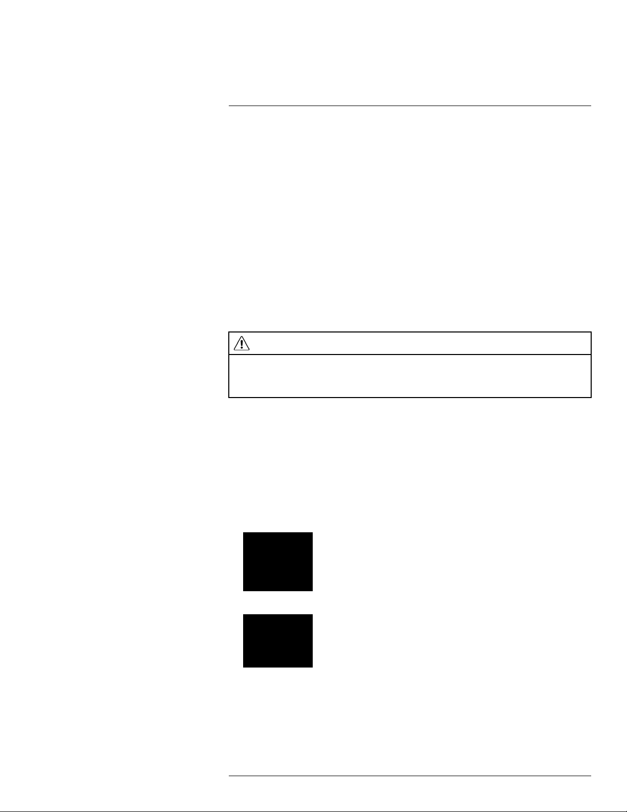
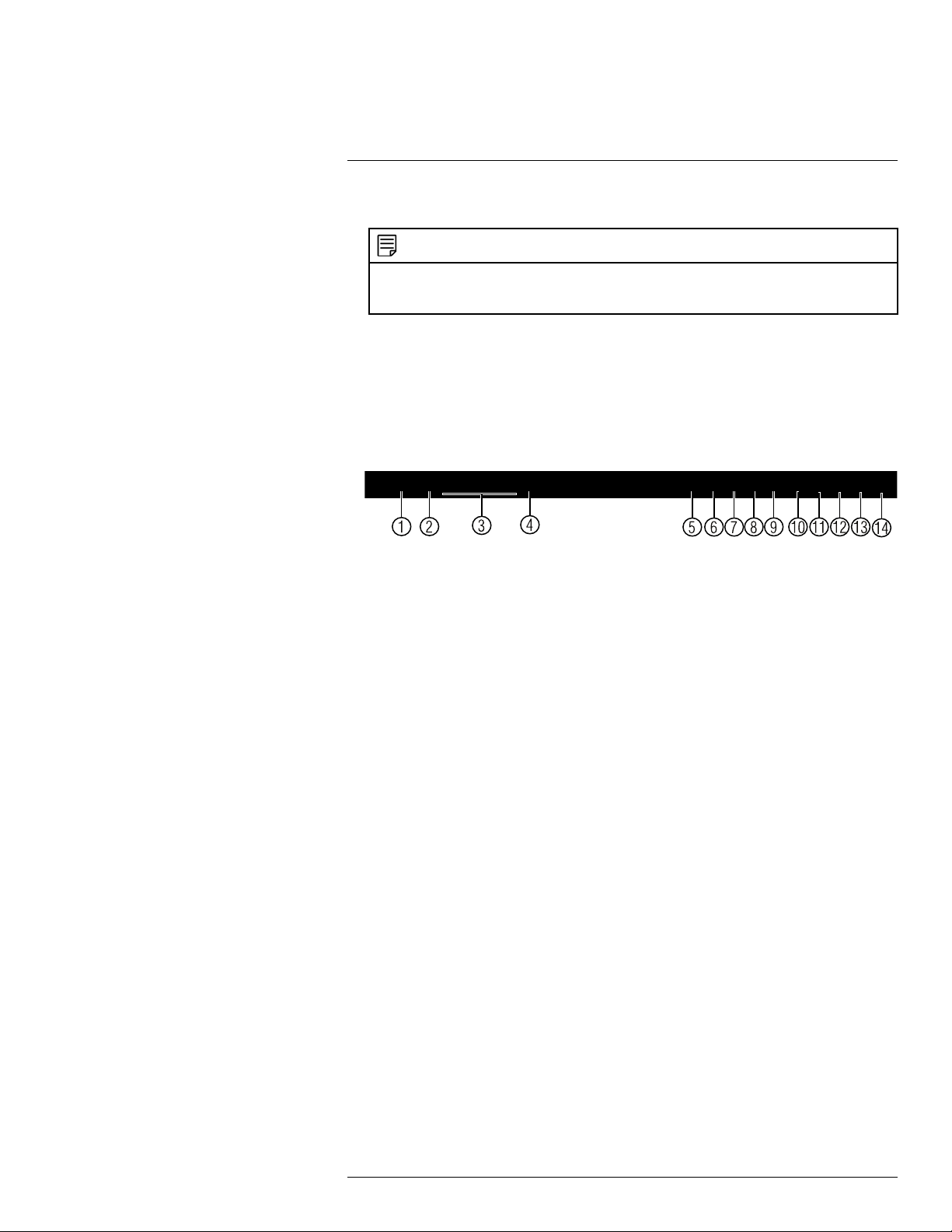
Front Panel (LNR600 Series)
1. IR receiver and LED indicators: IR receiver for the remote control. Keep the IR receiver clear from obstructions.
• Channel Indicators: Glow when camera is connected to the corresponding
channel.
• NET: Glows when network is in normal state. Turns off for network error.
• HDD: Glows to indicate hard drive is in normal state. Turns off when there is a hard
drive error.
• PWR: Glows to indicate the recorder is on.
2. Playback buttons:
•
Previous file: Press to skip to the previous video file on the system.
Next file: Press to skip to the next video file on the system.
•
Slow: Press to slow playback / decrease playback speed.
•
Fast: Press to speed up playback / increase playback speed.
•
Play backwards: Press to play video backwards / pause video.
•
Play: Press to play video / pause video.
•
3. SHIFT: During text input, press to switch input types.
4. REC: Press to open manual recording controls.
5. FN: Performs special functions in some menus.
6. ESC: In menus, press to go back / exit menus. In playback, press to return to live view.
7. Directional buttons:
•
• Directional buttons: Press to move cursor in menus. In live view, press up to
8. USB port: Connect a USB mouse (included) or connect a USB thumb drive (not included) for data backup or firmware upgrades.
9. Power button: Press and hold to power off the system (system password required).
Press to power the system back on.
: From live view, press once to open the System Information screen. In menus,
press to confirm menu options.
change split screen layout; press left / right to select channels when single-channel
mode is selected.
#LX400078; r.36882/36882; en-US
5
4
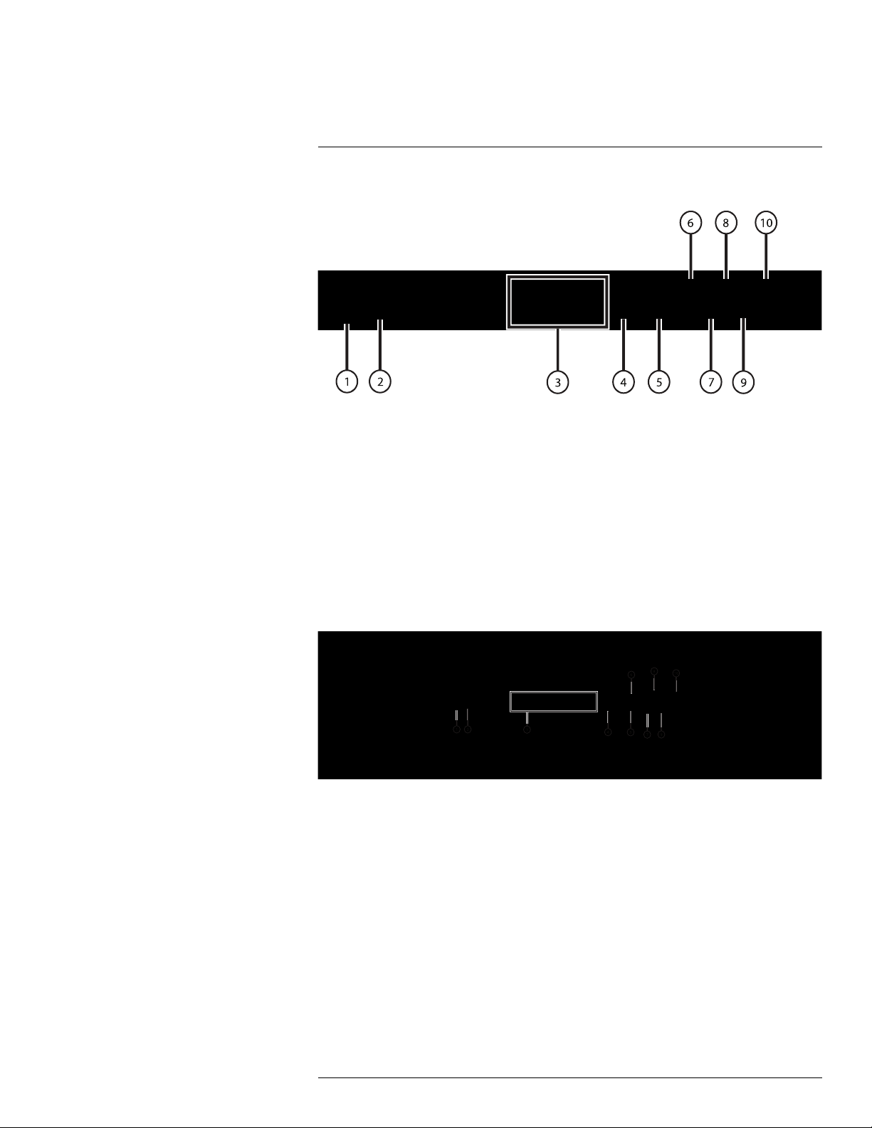
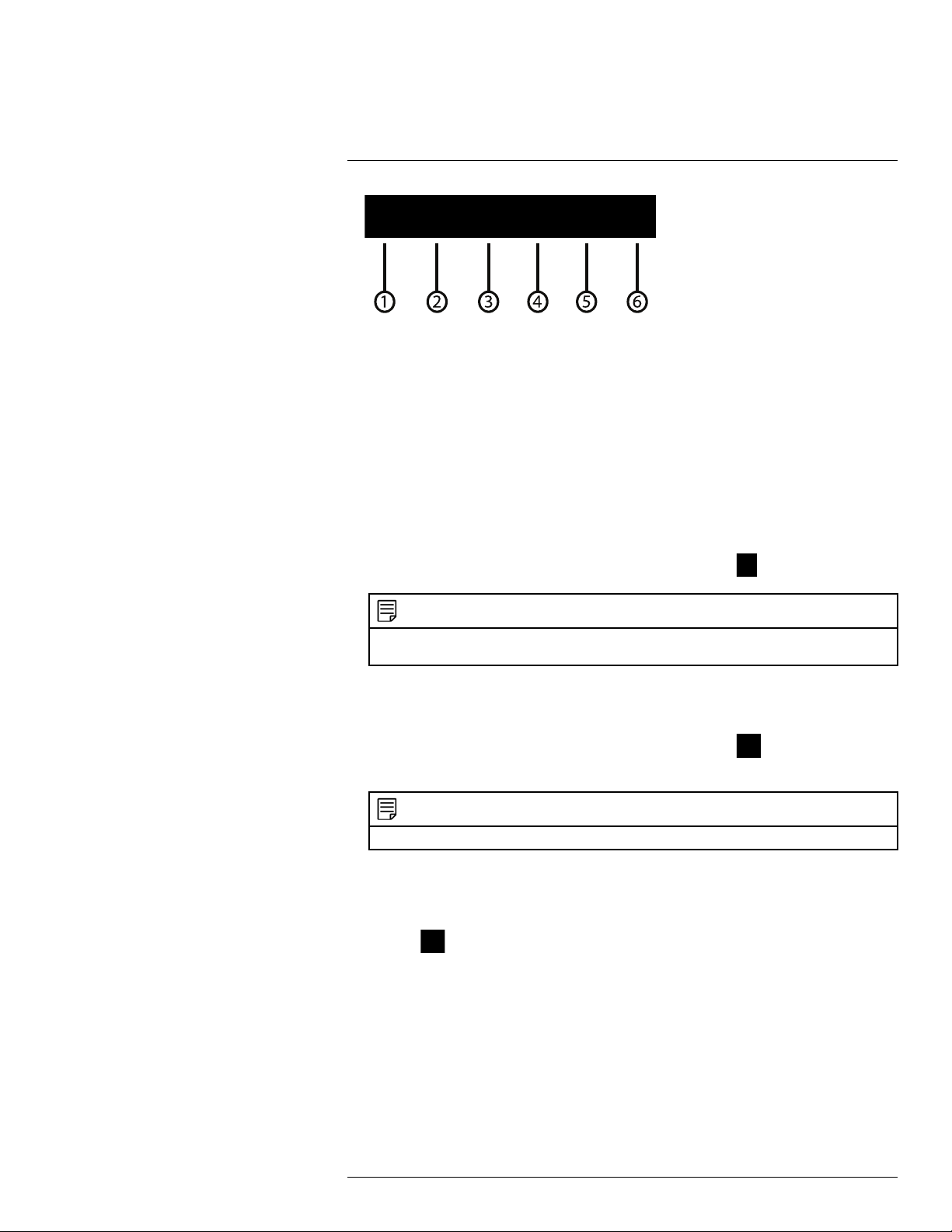
Rear Panel (LNR600 Series)
LNR608 (8-channel)
1. Power input: Connect the included AC power cable.
2. On / Off switch: Turns the NVR on or off.
3. PoE Ports: Connect IP cameras. Integrated PoE (Power Over Ethernet) ports provide
power to cameras and video connection to NVR.
4. LAN: Connect a CAT 5 RJ45 Ethernet cable for local and remote connectivity.
5. VGA: Connect a VGA monitor (not included) to view the system interface.
6. Audio IN/Audio OUT: Service only; not supported.
7. HDMI: Connect to an HDMI monitor or TV (not included) to view the system interface.
8. RS232: Service only; not supported.
9. USB port: Connect a USB mouse (included) or connect a USB thumb drive (not included) for data backup or firmware upgrades.
10. Alarm block: Connect alarm/sensor devices (not included).
LNR616 (16–channel) / LNR632 (32–channel)
1. Power input: Connect the included AC power cable.
2. On / Off switch: Turns the NVR on or off.
3. PoE Ports: Connect IP cameras. Integrated PoE (Power Over Ethernet) ports provide
power to cameras and video connection to NVR.
4. Alarm block: Connect alarm/sensor devices (not included).
5. HDMI: Connect to an HDMI monitor or TV (not included) to view the system interface.
6. VGA: Connect a VGA monitor (not included) to view the system interface.
7. USB port: Connect a USB mouse (included) or connect a USB thumb drive (not included) for data backup or firmware upgrades.
8. RS232: Service only; not supported.
9. LAN: Connect a CAT 5 RJ45 Ethernet cable for local and remote connectivity.
10. Audio IN/Audio OUT: Service only; not supported.
#LX400078; r.36882/36882; en-US
6
5
Basic Setup (LNR600 Series)
5.1 Step 1: Connect the IP Cameras
Option 1: Direct Connection to NVR
• Connect cameras to the PoE Ports on the rear panel of the NVR using Cat5e or higher
grade Ethernet cable. The cameras will appear on the NVR without any additional configuration when the system starts up.
NOTE
Compatible with Lorex HD IP cameras. For a list of compatible cameras, please visit
www.lorextechnology.com/support
Option 2: Connect Cameras to Local Network
You can also connect your IP cameras to your local network for flexible installations. For
details, see 5.11 Connecting Cameras to the Local Area Network (LAN).
5.2 Step 2: Connect the Mouse
• Connect a USB mouse (included) to one of the USB ports.
5.3 Step 3: Connect the Ethernet Cable
• Connect an Ethernet cable (included) to the LAN port on the rear panel of the system.
Connect the other end of the Ethernet cable to a router on your network.
#LX400078; r.36882/36882; en-US
7

5
Basic Setup (LNR600 Series)
5.4 Step 4: Connect the Monitor
• Connect the included HDMI cable from the HDMI port to the TVor monitor
(recommended).
OR
• Connect a VGA cable (not included) from the VGA port to the monitor.
1. VGA port.
2. HDMI port.
5.5 Step 5: Connect the Power Adapter to Power the NVR
• Connect the included AC power adapter to the NVR and connect the other end to a
power outlet or surge protector. Then turn the power switch to l to power on the NVR.
At startup, the system performs a basic system check and runs an initial loading sequence.
After a few moments, the system loads a live display view.
5.6 Step 6: Upgrade Firmware to Latest Version (if Available)
If a firmware upgrade is available, you will be asked to install it once the system starts up.
It is required to upgrade your system firmware and client software or mobile apps to the latest version to enable remote connection to the system.
#LX400078; r.36882/36882; en-US
8
5
Basic Setup (LNR600 Series)
If a firmware upgrade is available:
1. After startup, a notification will appear asking you to upgrade the firmware. Click OK to
upgrade.
2. Enter the system user name (default: admin) and password (default: 000000) and
click OK. Wait for the firmware update to complete. The system will restart once the
firmware has been upgraded.
WARNING
DO NOT POWER OFF THE SYSTEM OR DISCONNECT THE POWER CABLE DURING FIRMWARE INSTALLATION
5.7 Step 7: Verify Camera Image
• Power on the cameras, and then verify the camera video quality before mounting the
cameras to a permanent location.
• Mount the cameras under a sheltered location. Always verify the outdoor rating of your
camera before installing it in a permanent location.
5.8 Step 8: Set the Time
• Set the system time and date for accurate video time stamps. Videos with inaccurate
times may not be valid as surveillance evidence.
• For details on setting the system time, see 9 Setting The Time, page 23.
5.9 Default System Password & Port Numbers
CAUTION
By default, the system user name is admin and the password is 000000. It is essential that you create
your own password. For details, see 13 Managing Passwords and User Accounts, page 37.
The system requires a user name and password to log in to the system remotely using a
computer. After logging on remotely the first time through FLIR Cloud™, you will be asked
to create a custom password for the system.
Local system and remote connectivity (LAN & Internet) user name and password:
• Username: admin
• Password: 000000
Default ports for DDNS remote access:
• Port 80 (HTTP port)
• Port 35000 (Client port)
5.10 Quick Access to System Information
To quickly open a window that displays vital system information:
• Right-click to open the Quick Menu and click Info. Enter the system user name (default:
admin) and password (default: 000000).
OR
• Press the
button on the front panel.
OR
• Press the ENTER button on the remote control.
#LX400078; r.36882/36882; en-US
9
5
Basic Setup (LNR600 Series)
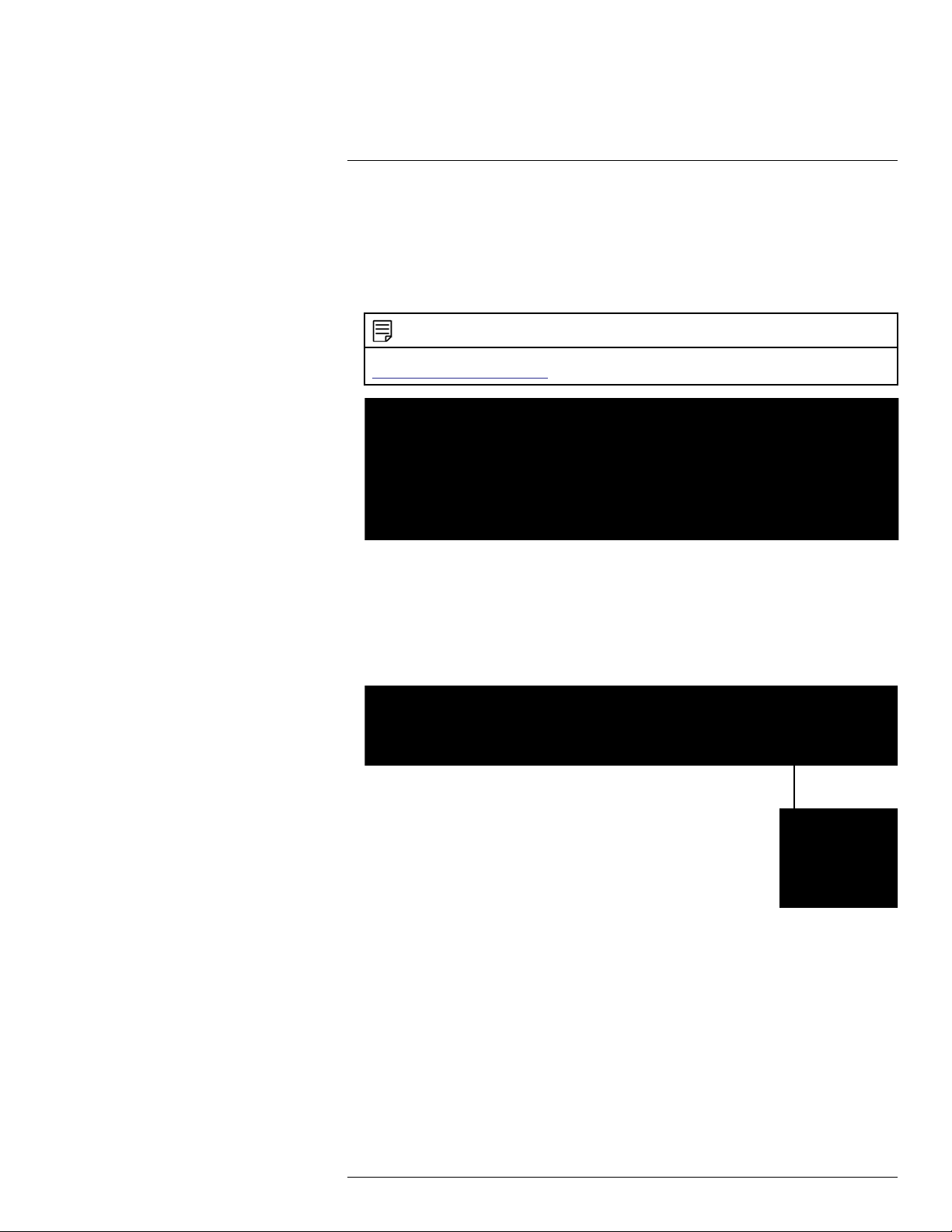
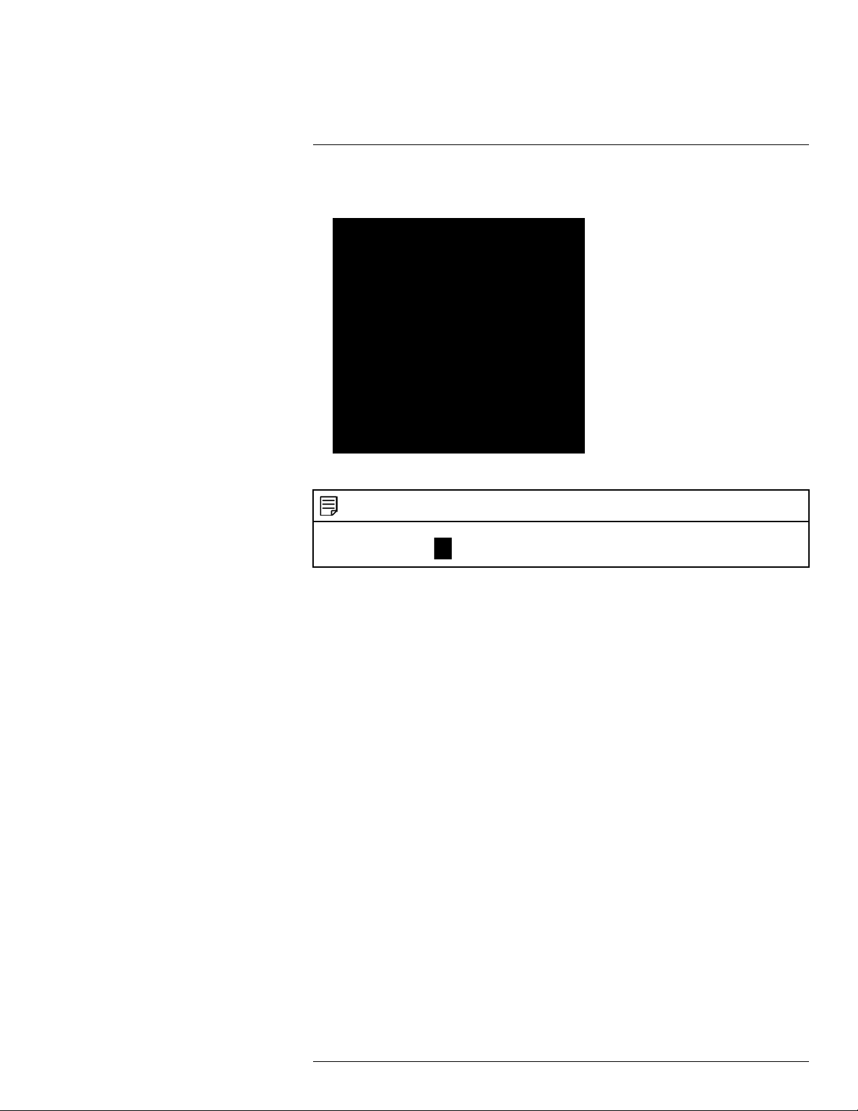
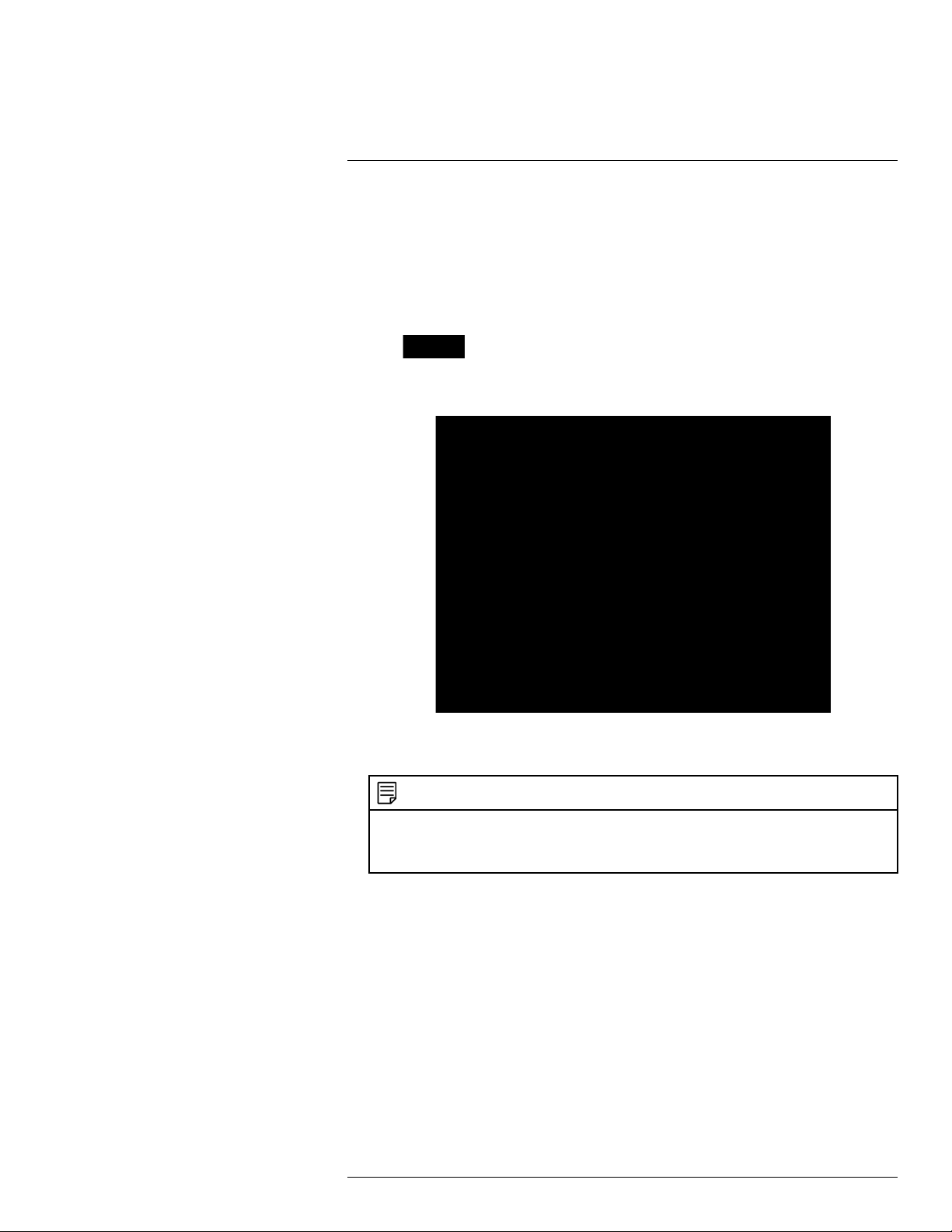
INFO Screen:
NOTE
The QR code shown in the System Info screen can be scanned during mobile setup to enter the system’s
Device ID.
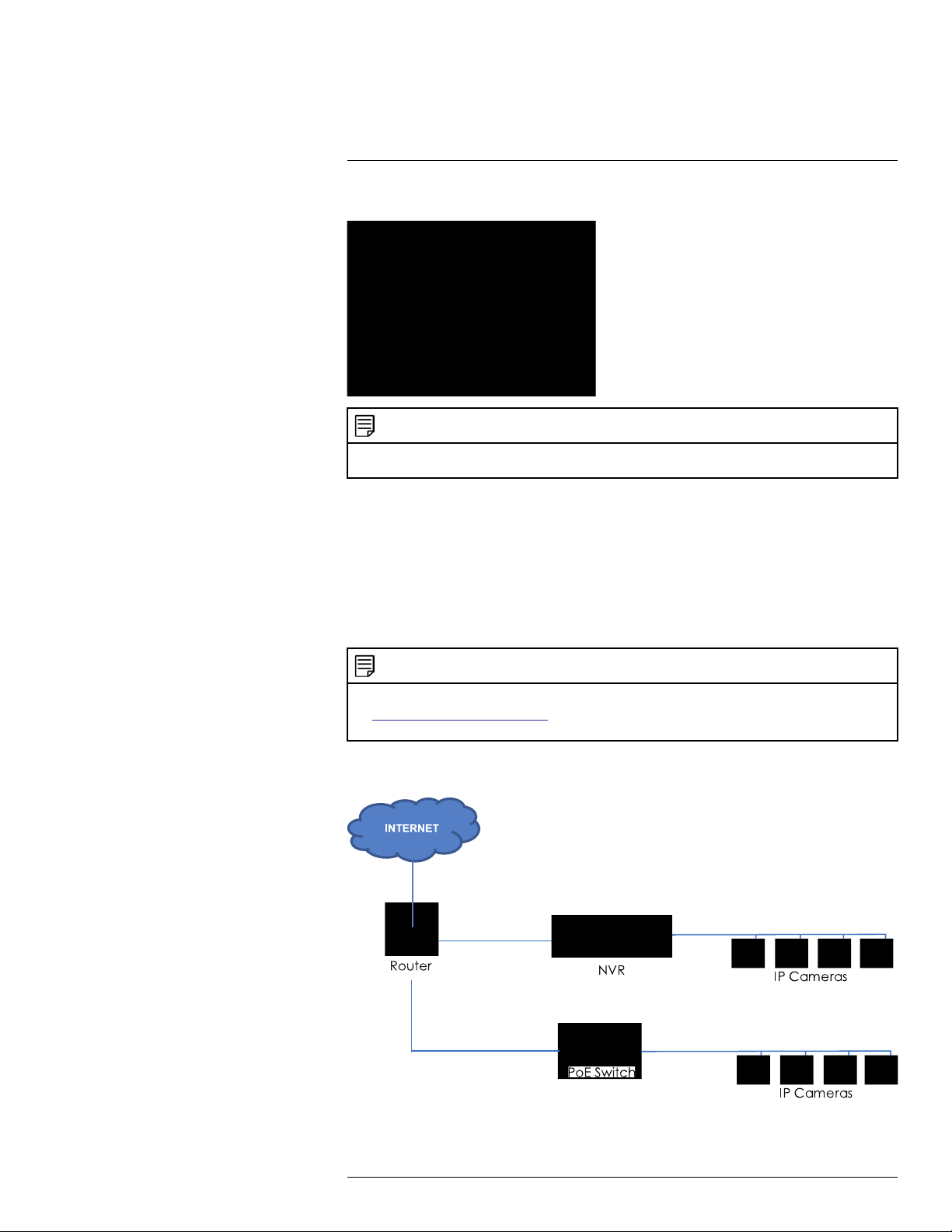
5.11 Connecting Cameras to the Local Area Network (LAN)
For flexibility, you may also connect IP cameras to the same Local Area Network (LAN) as
the NVR. This is accomplished by connecting the cameras to the same router as the NVR.
For these installations, an external PoE switch (sold separately) or power adapter (sold
separately) must be used to provide power to each IP camera. You also must add the cameras on the NVR before they will show a picture on the monitor or be recorded by the NVR.
Follow the steps below to connect the cameras to the NVR over the LAN.
NOTE
• Compatible with Lorex HD IP cameras. For a list of compatible cameras, please visit
www.lorextechnology.com/support.
• Camera and NVR images in this section are used for illustration only.
Step 1 of 2 — Option A: Connecting cameras to your local network using a PoE
switch:
#LX400078; r.36882/36882; en-US
10
5
Basic Setup (LNR600 Series)
1. Connect an Ethernet cable from the LAN port on an external PoE switch (sold separately on www.lorextechnology.com) to your router using a CAT5e or higher Ethernet
cable. Connect the power cable to the PoE switch and to a power outlet or surge
protector.
NOTE
Terminology may vary depending on the model of PoE switch you have.
2. Connect the IP cameras to the PoE switch using the Ethernet extension cables. The
PoE switch will provide power and video transmission the same way as your NVR.
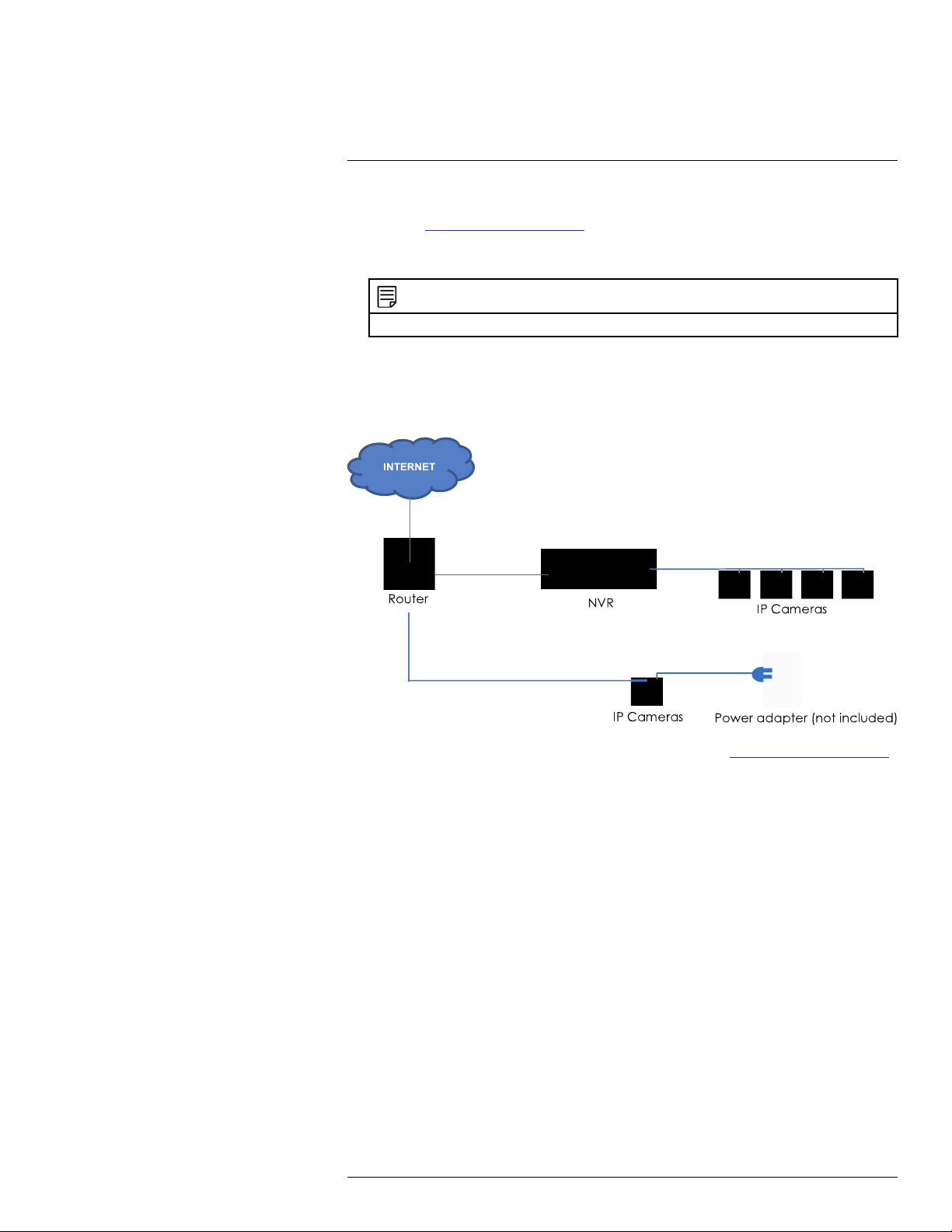
Step 1 of 2 — Option B: Connecting cameras to your local network using power
adapters:
1. Connect each camera to a compatible power adapter (visit www.lorextechnology.com
for compatible power adapters for your cameras).
2. Connect the camera to your router using a CAT5e or higher Ethernet cable.
Step 2 of 2: Add the cameras to your NVR:
1. Right-click and select Device Search.
2. Log in using the admin account (default User Name: admin; default password:
000000).
3. Click Device Search. The system searches the network for compatible cameras.
4. Check the camera(s) you would like to add.
#LX400078; r.36882/36882; en-US
11
5
Basic Setup (LNR600 Series)
5. Click Add. The Status indicator turns green to show the camera is successfully
connected.
6. Click OK to save changes.
NOTE
You can also add a camera to a specific channel by hovering the mouse over an empty channel in split-
screen view and clicking
. Then double-click the camera you would like to add and right click to exit.
#LX400078; r.36882/36882; en-US
12
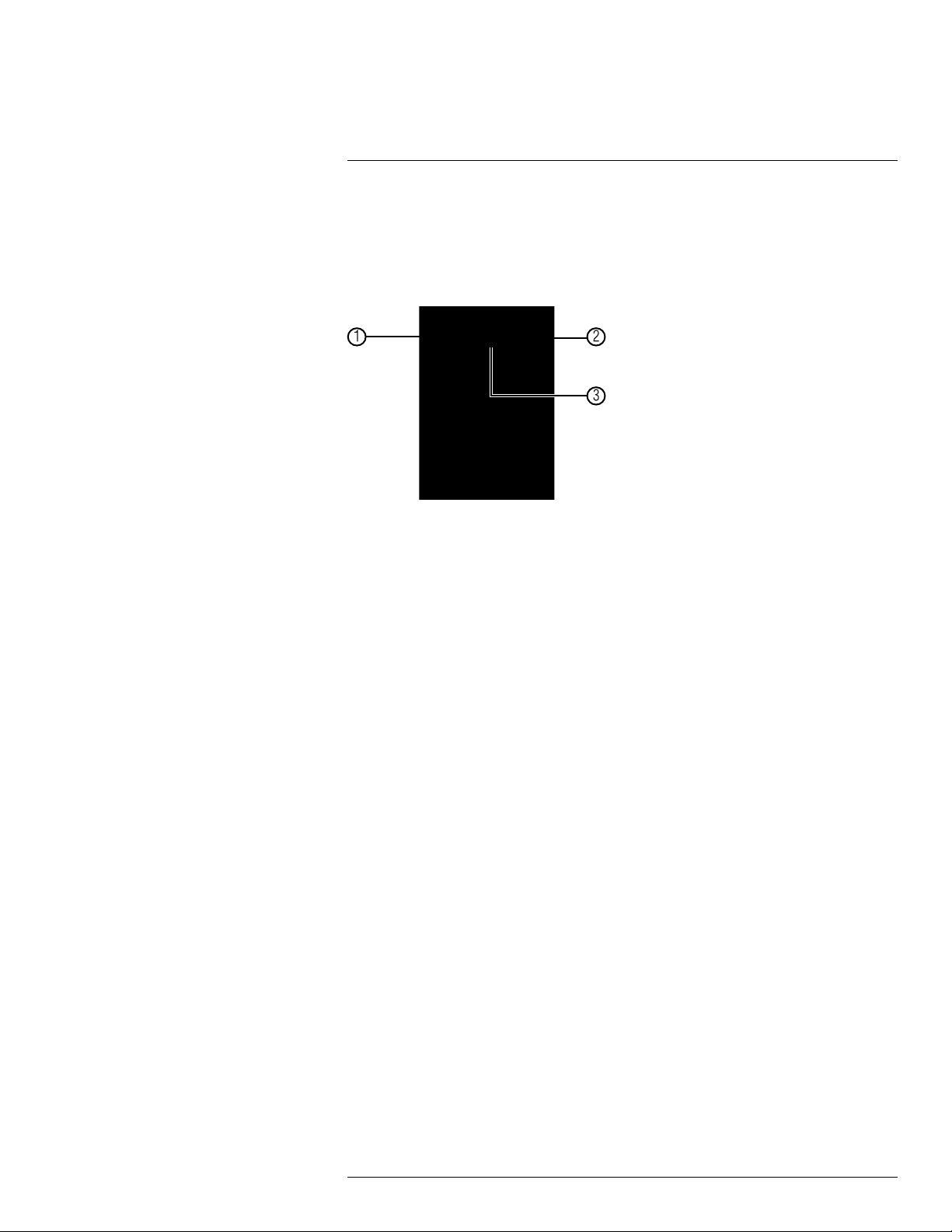
6
Mouse Control
The mouse is the primary control device for the system. To connect a USB mouse:
• Connect a USB mouse to the USB port on the front or rear panel.
• In live view, hover the mouse cursor over the bottom of the screen to open the Naviga-
tion Bar. Move the mouse cursor away from the bottom of the screen to close the navigation bar.
1. Left-button:
• In live view, while in a split-screen display mode, click an individual channel to view
it in full-screen. Click again to return to the split-screen display mode.
• While navigating menus, click to open a menu option.
2. Right-button:
• During live view, right-click anywhere on the screen to open the Quick Menu.
• Within system menus, right-click to exit menus.
3. Scroll wheel: In live view, use the scroll wheel to zoom in/out.
#LX400078; r.36882/36882; en-US
13
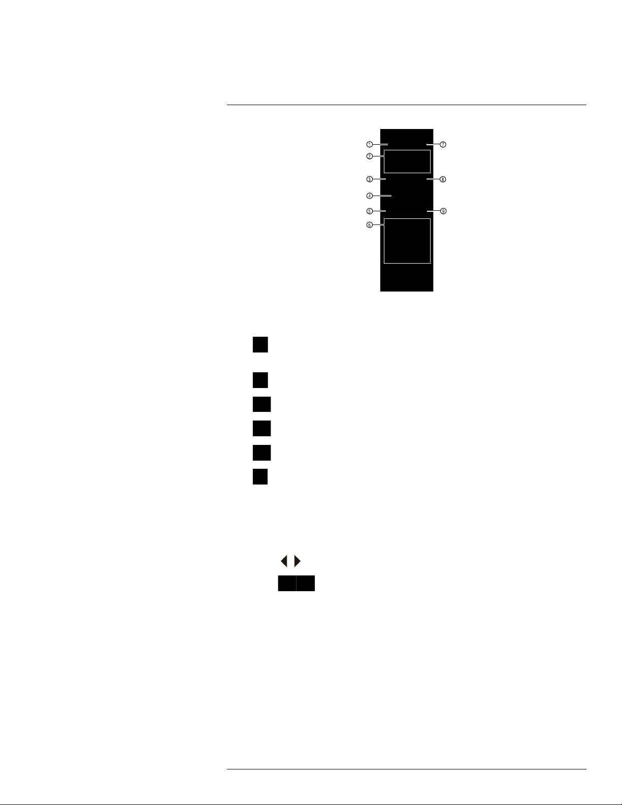
7
Remote Control
1. Power: Press and hold to power off the system. Press to power on.
2. Playback controls:
Pause/Play: In live view, press to enter playback mode. Press to play/pause
•
playback.
Reverse: Press to reverse playback/pause playback.
•
•
•
•
•
3. Esc: In menus, press to go back / exit menus. In playback, press to return to live view.
4. Directional keys:
• Enter: Press once to open the System Information screen. Press to confirm menu
• Press
• Press
5. Mult: Press to switch between full-screen and split-screen layouts.
6. Number keys:
• 1~0: In live view, press to open channels in full-screen.
• In menus, press to input numbers or text input.
• Shift: Press to change input types.
7. Add: Configure remote control address. See below for details.
8. Rec: Press to open manual record menu.
9. Fn: Press to perform special functions in some menus.
Fast: Press to increase playback speed.
Next: Press to skip to next video.
Previous: Press to skip to previous video.
Slow: Press for slow playback.
selections.
to move the menu cursor.
to change menu options.
#LX400078; r.36882/36882; en-US
14
7
Remote Control
7.1 Setting the Remote Control Address
If you have more than one system, you can set up your remote control to pair with a specific system.
To set the remote control address:
1. Right-click and click Main Menu. Enter the system user name (default: admin) and
password (default: 000000).
2. Click
and then click Setting>General>General.
3. Under Device No., enter the address number you would like to assign to the remote
control.
4. Click OK.
5. Using the remote control, press Add. Then enter the address number and press Enter.
NOTE
When entering the address number using the remote, make sure that you press three digits. A single-digit number should be preceded by two zeros. A two-digit number should be preceded by one
zero. For example, if you entered 8 as the Device No., you have to press Add then 008 on the
remote.
#LX400078; r.36882/36882; en-US
15
8
Using the System
Use the system’s graphical on-screen display to navigate menus and configure options
and settings.
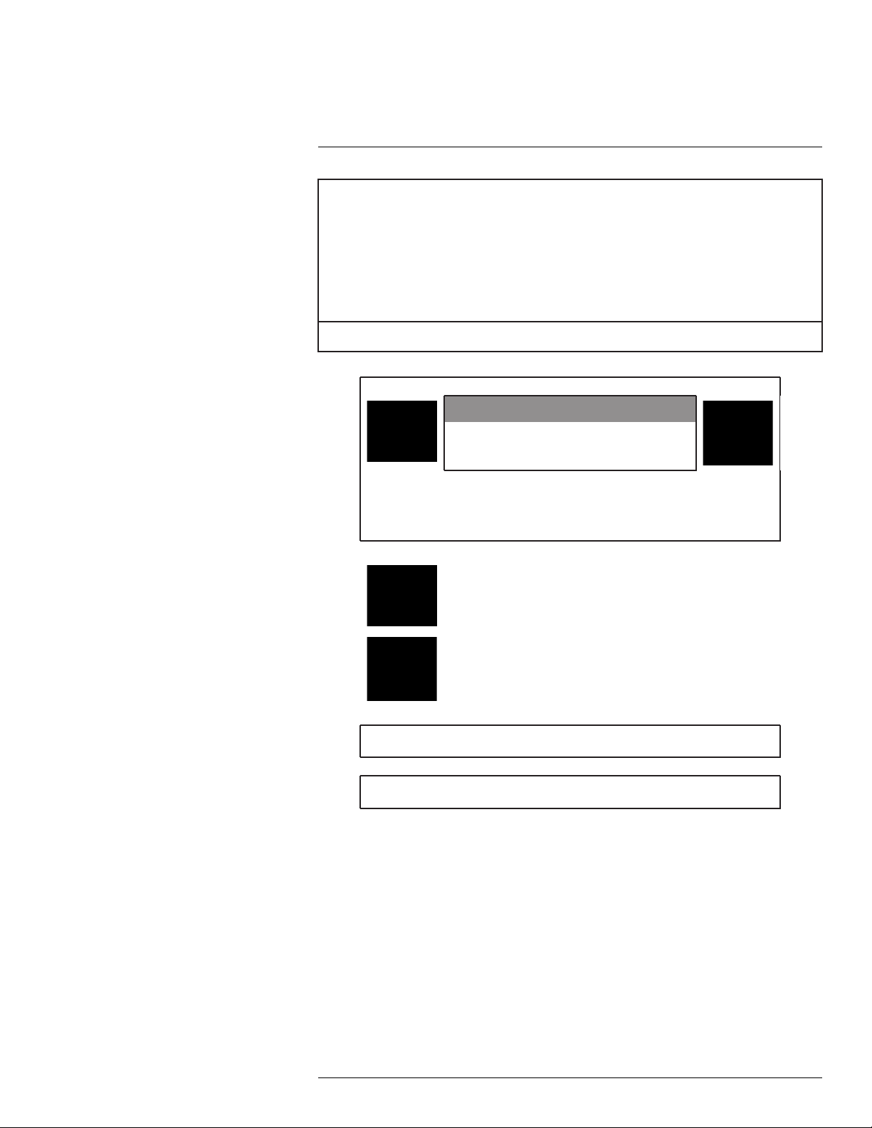
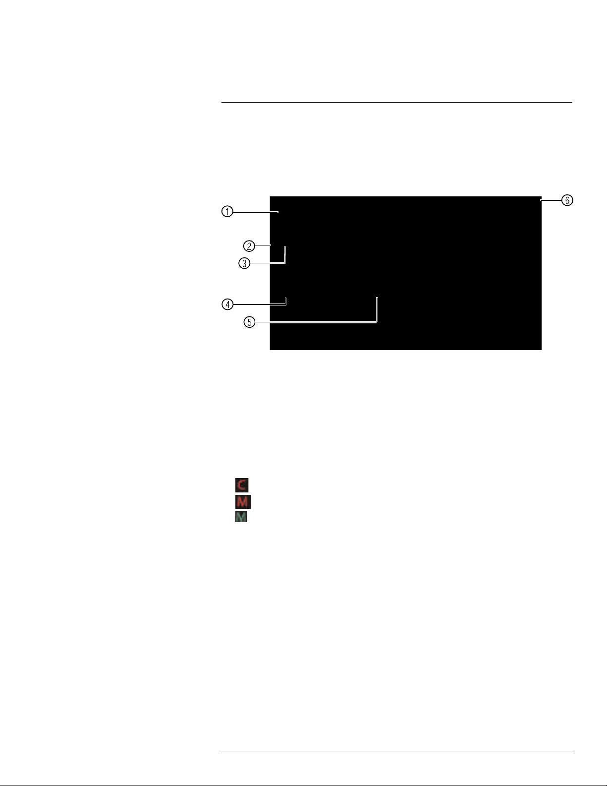
8.1 On-Screen Display
The system shows the following for all display views:
1. Display area:
• Click on a channel to view in full-screen; click again to return to split screen.
• Right-click to open the Quick Menu.
• Hover the mouse cursor over the bottom of the screen to open the Navigation Bar.
Move the mouse cursor away from the bottom of the screen to close the navigation
bar.
• Move the mouse to the top of a channel to view the Camera Toolbar.
• Click-and-drag cameras to rearrange the channel display. This does not affect the
channels each camera is connected or recording to.
2. Channel name
3.
: Camera is continuously recording.
4.
: Motion has been detected and video is recording.
5.
: Motion has been detected but video is not recording.
6. Date & time: Current system date and time. For details on setting the date and time,
see 9 Setting The Time, page 23.
#LX400078; r.36882/36882; en-US
16

8
Using the System
8.2 Using the Quick Menu
The Quick menu gives you access to the system’s key functions. To access the Quick
Menu, right-click the screen during live view.
The Quick Menu has the following options:
• View: Select a camera in full-screen or select a multi-channel display.
• Pan/Tilt/Zoom: Access controls for PTZ cameras (not included).
• Fish Eye: Access controls for Fish Eye cameras (not included).
• AutoFocus: Access zoom/focus controls for auto-focus cameras (not included).
• Camera Setting: Configure image settings for cameras.
• Info: Opens the system information window.
• Sequence: Click to start/stop sequence mode.
In sequence mode, the system will automatically cycle through connected cameras
every few seconds. A
will appear to show that sequence mode is on.
Click the icon to pause sequence mode on the channel that is currently shown (icon
changes to
). Click again to resume sequence mode. Right-click and select Se-
quence to return to normal viewing mode.
• Disable Beep: Disable beeping alarms.
• Search: Search/playback recorded video. See 11 Search (Playback), page 26
• Manual Control: Click Record to open the Record menu to select manual recording
options. See 10.3 Setting up Scheduled or Manual Recording, page 24. Click Alarm
Output to control alarm output devices (not included).
• Device Search: Open the Device Search menu to manage IP cameras over the local
network.
• Main Menu: Open the Main Menu. See 14 Using the Main Menu, page 41.
8.3 Adjusting Camera Image Settings
Use the Camera Setting menu to adjust image settings for your cameras.
To adjust image settings:
1. Right-click on the channel you would like to configure and select Camera Setting. Enter the system password if prompted.
#LX400078; r.36882/36882; en-US
17
8
Using the System
2. Configure the following settings as needed:
NOTE
The settings listed below are only shown if they are supported on the selected camera. Some camera
models do not support all settings.
• Mirror: Select Enable to flip the image horizontally.
• Flip: Select Flip 180° to flip the image vertically, or select No Flip for the default ori-
entation. You can also select the options, Clockwise 90° or Anticlockwise 90°.
• Corridor Mode: Not supported.
• 3D NR: Select Enable to turn on the camera’s noise reduction feature. Noise reduc-
tion will ensure a cleaner image, especially at night, and may reduce the amount of
disk space required to store video.
• Backlight Mode: Select one of the following:
◦ Backlight Mode: Adjusts the lighting levels in the picture so you can see objects
in the foreground if there is a strong light source behind them.
◦ WDR: The camera compensates for changes in brightness across the image to
enhance the picture quality of both light and dark areas.
◦ HLC: The camera dims the brightest areas of the image to make them clearer.
◦ Off: Disable this function.
• Scene Mode: This mode allows you to adjust white balance levels for the camera.
Select Auto for the camera to automatically adjust the white balance. Select Sunny
or Night to use preset white balance levels. Select Customized to manually set
blue and red levels.
• Day&Night: This setting sets the camera’s day/night mode. Select Color for the
camera to use color mode at all times. Select Auto for the camera to automatically
determine whether to use color or black and white mode. Select Black&White for
the camera to use black and white mode at all times.
NOTE
It is recommended to select Auto mode, as using Color mode may impact the camera’s performance at night.
• Saturation: Adjust the vibrancy of colors in the image.
• Brightness: Adjust the image brightness.
• Contrast: Adjust the image contrast.
• Hue: Adjust the color hue of the image.
#LX400078; r.36882/36882; en-US
18
8
Using the System
3. Click OK to save changes.
NOTE
You must save changes to apply settings changes. It is recommended to adjust one setting at a time
so you can see the results of each change. Click Default to reset the camera to default image
settings.
8.4 Using the Navigation Bar
The Navigation Bar gives quick access to certain functions and menus.
To open the Navigation bar:
• In live view, hover the mouse cursor over the bottom of the screen to open the Navigation Bar. Move the mouse cursor away from the bottom of the screen to close the navigation bar. The Navigation Bar has the following options:
1. Main Menu.
2. Collapse.
3. Select display layout.
4. Sequence Control: Click to start/stop sequence mode.
5. PTZ: Click to open PTZ controls.
6. Camera: Click to open camera image settings.
7. Search: Search and playback recorded video. See 16.4 Playback, page 90.
8. Alarm Status: View alarms in progress. See 14.2.4 Event Info, page 50.
9. Channel Info: Click to access status information about connected cameras.
10. Remote Device Search: Manage IP cameras over the network.
11. Network: Configure network settings for your system. See 14.3.1 Network, page 53.
12. HDD Manager: Manage hard drives connected to the system. See 14.3.21 Format-
ting the Hard Drive, page 69.
13. USB Manager: Click to access options for connected USB thumb drives (not in-
cluded). You can backup video, logs, or system configurations and install firmware
upgrades.
14. System Upgrade: Check for firmware upgrades. The system must be connected to
the Internet to check for or receive updates.
8.5 Using the Camera Toolbar
The Camera Toolbar is used to perform actions on a specific channel.
To access the Camera Toolbar:
• Move the mouse to the top of the channel display. The Camera Toolbar has the following options:
#LX400078; r.36882/36882; en-US
19
8
Using the System
1. Instant Playback.
2. Zoom.
3. Real-time Backup.
4. Snapshot.
5. Audio Talk.
6. Remote Device.
8.5.1 Using Instant Playback
Instant Playback is used to playback the last 5~60 minutes of video from the selected
channel. You can also access Quick Playback in split-screen mode, while still viewing live
video from the other channels.
To use Instant Playback:
1. Move your mouse to the top of the channel display and click
NOTE
By default, the system will begin playback from 5 minutes ago. You can increase this to up to 60 minutes using the Instant Playback setting in Main Menu>Setting>General.
.
2. Right-click to exit Instant Playback.
8.5.2 Using Digital Zoom in Live Display
1. Move your mouse to the top of the channel display and click
to activate digital
zoom. A check mark will appear in the icon to indicate digital zoom is activated.
NOTE
You may activate digital zoom in multiple channels at the same time.
2. Click and drag inside the channel to zoom in.
• Click and drag to pan the zoom area.
• Right-click to zoom out and select a new zoom area.
• Click
to disable digital zoom. Note that the channel will remain at the same
zoom level until you right-click inside it.
8.5.3 Using Real-time Backup
Real-time backup allows you to save footage from the live display to a USB thumb drive
(not included) or external hard drive (not included).
To use Real-time Backup:
1. Insert the USB thumb drive or external hard drive into one of the USB ports on the
system.
#LX400078; r.36882/36882; en-US
20
8
Using the System
2. Move your mouse to the top of the channel display and click to start Real-time
Backup.
3. Click
If the system prompts you to log in, you will need to click
logging in.
again to end Real-time Backup. The file is saved to your USB device.
NOTE
again to start Real-time Backup after
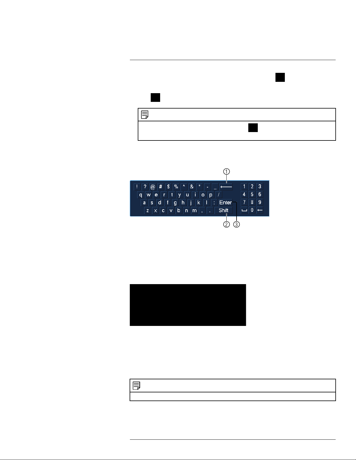
8.6 Using the Virtual Keyboard
The Virtual Keyboard is used to input text or numeric values in certain menus.
1. Backspace.
2. Enter capital letters.
3. Confirm entry.
8.7 Adjusting Camera Zoom & Focus
Auto-focus cameras (not included) have a motorized lens. The motorized lens allows you
to control the zoom and focus settings using the menus on your system.
To adjust the camera’s zoom focus:
1. Click on the channel where the motorized lens camera is connected.
2. Right-click and then click AutoFocus. Log into the system using the admin account
(default user name is admin and password is 000000).
3. Adjust the zoom and focus using the following options:
• Use the sliders to adjust the Zoom or Focus settings for the camera.
NOTE
Hover the mouse over the sliders and use the mouse wheel to adjust by 1% at a time.
• Click the AutoFocus button to automatically focus the camera at the current zoom
level.
• Click Reset to return the camera to the default zoom and focus levels.
#LX400078; r.36882/36882; en-US
21

8
Using the System
• Click Refresh to refresh the settings shown on the system if someone has used the
manual lens controls on the camera.
4. Right-click to exit and save changes.
#LX400078; r.36882/36882; en-US
22
 Loading...