

Page 1

www.lorextechnology.com
REMOTE SURVEILLANCE
INTERNET CAMERA
INSTRUCTION MANUAL
English Version 3.0
MODELS:
LN SERIES
Copyright © 2010 Lorex Technology Inc.
www.lorextechnology.com
Page 2
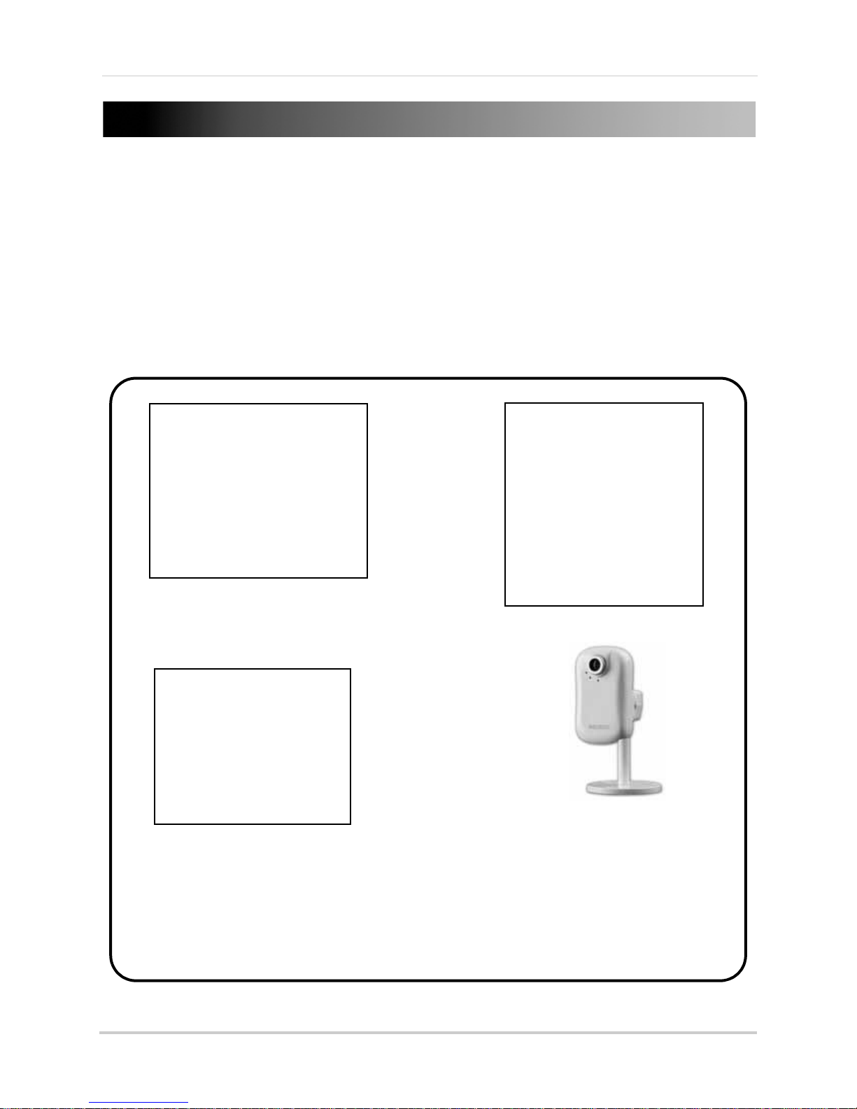
Thank you for purchasing the Lorex Remote Surveillance Internet Easy-Connect Camera.
This manual refers to the following models:
• LNE1001, LNE1001i: Wired, Easy Connect, Internet Camera
• LNE3003, LNE3003i: Wired/Wireless, Day/Night, Easy Connect, Internet Camera
• LNZ4001,LNE4001i:
Wired/Wireless, Day/Night, Pan/Tilt, Easy Connect, Internet Camera
To learn more about this product and to learn about our complete range of accessory
products, please visit our website at:
www.lorextechnology.com
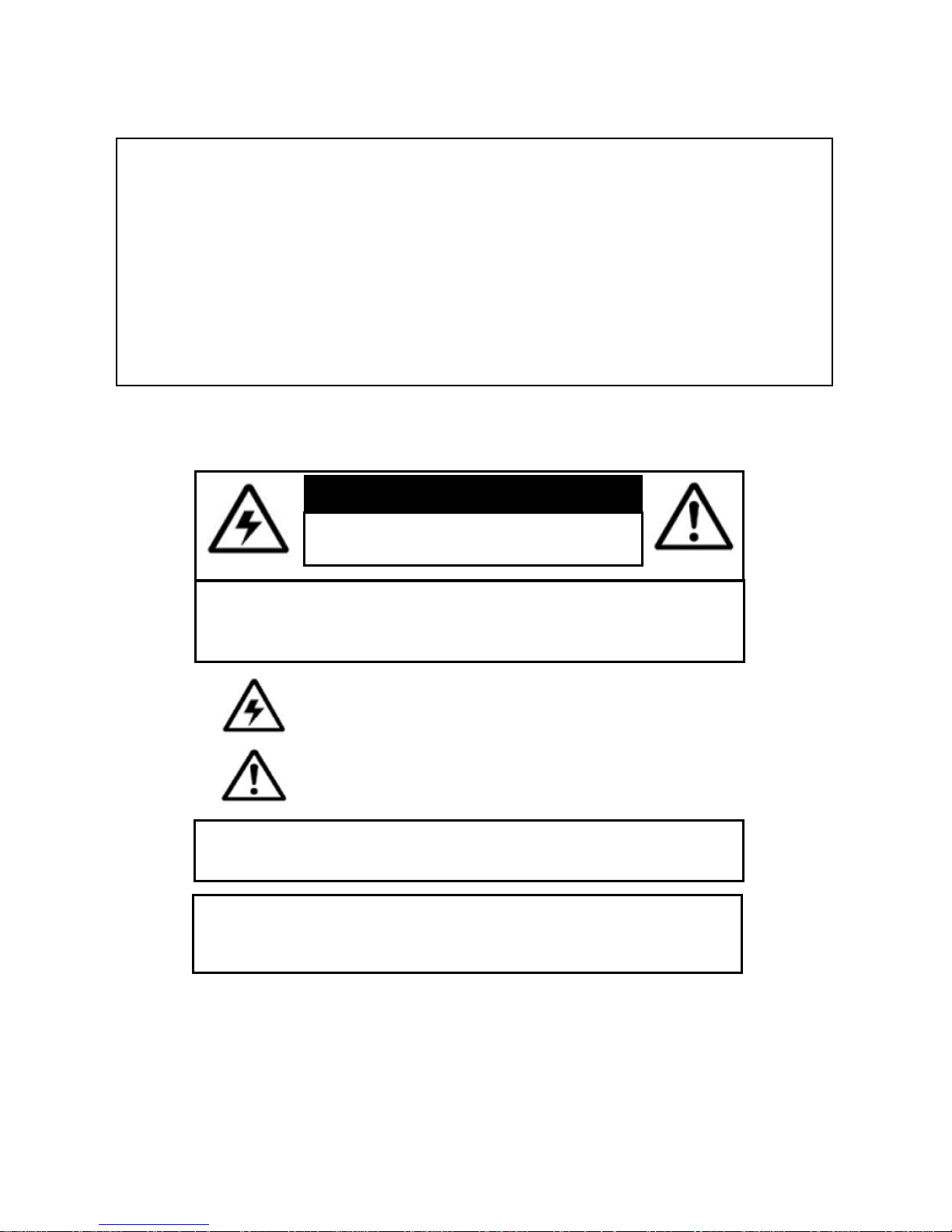
CAUTION
RISK OF ELECTRIC SHOCK
DO NOT OPEN
CAUTION: TO REDUCE THE RICK OF ELECTRIC SHOCK DO NOT
REMOVE COVER. NO USER SERVICABLE PARTS INSIDE.
REFER SERVICING TO QUALIFIED SERVICE PERSONNEL.
The lightning flash with arrowhead symbol, within an equilateral
triangle, is intended to alert the user to the presence of uninsulated
"dangerous voltage" within the products ' enclosure that may be of
sufficient magnitude to constitute a risk of electric shock
The exclamation point within an equilateral triangle is intended to
alert the user to the presence of important operating and
maintenance (servicing) instructions in the literature accompanying
the appliance.
WARNING: TO PREVENT FIRE OR SHOCK HAZARD, DO NOT
EXPOSE THIS UNIT TO RAIN OR MOISTURE.
CAUTION: TO PREVENT ELECTRIC SHOCK, MATCH WIDE BLADE
OF THE PLUG TO THE WIDE SLOT AND FULLY INSERT.
Page 3

NEED HELP?
CONTACT US FIRST
DO NOT R E T U R N THIS PRODUCT TO TH E STORE
Please make sure to register your product at www.lorextechnology.com to receive product updates and information
3 EASY WAYS TO CONTACT US:
Online:
Pr o du c t S u pp o rt i s a va i l ab l e 2 4 /7 in c l ud i ng p ro d uc t
in f or m a ti o n, u s er ma n u al s , q u i ck st a r t u p g u id e s a nd FA Q’s
at www.lorextechnology.com/support
To o r d er ac c es s o ri e s, v i si t
www.lorextechnology.com
By Email:
Te ch n i ca l S u pp o r t ( for te c hn i c al / in s t al l at i o n i ss u e s)
support@lorex c o r p.com
Cu s to m er C ar e ( f o r w ar r a nt y a n d a c ce s so r y sa l es )
customerservice@lorexcorp. c o m
Cu s to m er F ee d ba c k
info@lorex c o r p.com
By Phone:
NORTH AMERICA:
CUSTOMER SERVICE: 1-888-425-6739 (1-888-42-LOREX)
TECH SUPPORT: 1-877-755-6739 (1-877-75-LOREX)
MEXICO: 1-866-427-6739
INTERNATIONAL: +800-425-6739-0
(Ex am ple : Fr om th e U K, dia l 00 in st ea d o f +)
Ve rs i o n 8 - Ap ri l 27 2 0 1 0
Page 4

NECESITA AYUDA
VOUS AVEZ BESOIN
D’AIDE?
COMUNÍQUESE PRIMERO
CON NOSOTROS
NO DEVUELVA ESTE PRODUCTO A LA TIENDA
Cerció rese de p or fa vor coloc ar s u pro ducto en www.
lorexc ctv.co m/reg istr ation par a rec ibir actu alizaciones y la inform ación del prod ucto
3 maner as s encillas de comun icar se
co n no sotros:
www
En línea:
apoyo al producto disponi ble 24/7 incluyendo información
del prod ucto, manuales para el usuario, guías de inicio
rápido y preguntas más frecuentes en
www.lorextechnology.com/support
Para col ocar pedidos de accesorios, visite
www.lorextechnology.com
CONTACTEZ-NOUS
D’ABORD
NE RETOURNEZ PAS CE PRODUIT AU MAGASIN
Veu illez vei ller à en regis trer votr e produit à www.
lorexc ctv.co m/reg istr ation pou r rec evoir des mises à
jour e t l’infor matio n de prod uit
3 façon s fa ciles de nous con tacter:
www
En ligne:
le suppo rt des produits est disponible 24 heures sur 24, 7
jours su r 7, y compris les inf ormations sur les produits, les
guides d e l’utilisateur, les guides de d émarrage rapide et
les foires à questions
www.lorextechnology.com/support
Pour com mander des accessoires, visitez
www.lorextechnology.com
Por Correo Electrónico:
soporte técnico (para asuntos técnicos/la instalación)
support@lorexcorp.com
O
servicio al cliente (respecto a la garantía y a la venta
de acces orios)
customerservice@lorexcorp.com
Comentar ios de cliente
info@lorexcorp.com
Por Teléfono:
L’AMÉRIQUE DU NORD:
ATENCIÓN AL CLIENTE: 1-888-425-6739 (1-888-42-LOREX)
SOPORTE TÉCNICO: 1-877-755-6739 (1-877-75-LOREX)
MEXICO: 1-866-427-6739
INTERNACIONAL: +800-425-6739-0
(Ejemplo: Desde el Reino Unido, marque el 00 en lugar del +)
sus opiniones son bienvenidas en
info@lorexcorp.com
para colocar pedidos de accesorios, visite
Par Courriel:
support technique (pour les questions techniques et
d’instal lation) support@lorexcorp.com
OU
service à la clientèle (pour les questions de garantie
et les v entes d’accessoires)
customerservice@lorexcorp.com
Commenta ires des clients
info@lorexcorp.com
Par Téléphone:
NORTE AMÉRICA:
SERVICE À LA CLIENTÈLE: 1-888-425-6739 (1-888-42-LOREX)
SUPPORT TECHNIQUE: 1-877-755-6739 (1-877-75-LOREX)
MEXICO: 1-866-427-6739
INTERNATIONAL: +800-425-6739-0
(Exemple: À partir du Royaume-Uni, composez 00 au lieu de +)
nous serions heureux de recevoir vos
commentaires à info@lorexcorp.com pour
commander des accessoires, visitez
www.lorextechnology.com
www.lorextechnology.com
Ve rs i o n 8 - Ap ri l 27 2 0 1 0
Page 5

B E F O R E Y O U S T A R T
THIS PRODUCT MAY REQUIRE PROFESSIONAL INSTALLATION
LOREX IS COMMITTED TO FULFILLING YOUR SECURITY NEEDS
• We have developed user friendly products and documentation.
Please read the Quick Start Guide and User Manual before you
install this product.
• Consumer Guides and Video Tutorials are available on our web
site at www.lorextechnology.com/support
• If you require further installation assistance, please visit
www.lorextechnology.com/installation or contact a
professional installer.
• Please refer to the “Need Help” insert for technical support and
customer care information.
• Please note that once the components of this product have been
unsealed, you cannot return this product directly to the store
without the original packaging.
April 27 2010 R3
www.lorexcctv.com
Page 6

AVANT DE
A N T E S D E
COMMENCER
CE PRODUIT POURRAIT EXIGER UNE
INSTALLATION PROFESSIONNELLE
LOREX S’ENGAGE À SATISFAIRE
VOS BESOINS SÉCURITAIRES
• Veuillez lire le guide de démarrage rapide et le
mode d’emploi avant d’installer ce produit.
• Les guides du consommateur et les séances
de tutorat vidéo sont disponibles sur l’Internet en
visitant www.lorextechnology.com/support
• Si vous avez besoin de l’aide pour l’installation,
E M P E Z A R
ESTE PRODUCTO PUEDE EXIGIR UNA
INSTALACIÓN PROFESIONAL
LOREX SE COMPROMETE A SATISFACER
SUS NECESIDADES EN SEGURIDAD
• Favor de leer la guía de instalación rápida y la
guía del usuario antes de instalar este producto.
• Puede conseguir las guías del consumidor y
los cursos en enseñanza video sobre el Internet
visitando www.lorexcctv.com/support
• Si necesita ayuda para la instalación, visite
veuillez visiter www.lorextechnology.com/installation
ou contactez un spécialiste en installation
• Veuillez référer à l’insert “Need Help” pour
ob¬tenir de l’information sur le service à la cli-
entèle et le support technique
• Veuillez constater qu’une fois que les
com¬posantes de ce produit ont été retirées de
l’emballage, vous ne pourrez plus retourner ce
produit directement au magasin.
www.lorextechnology.com/installation o contacte un
especialista en instalaciones
• Favor de referir al documento “Need Help” para
obtener información acerca del servicio al cliente
y al soporte técnico
• Favor de notar que una vez que los compo-
nentes de este producto han sido removidos del
embalaje, no podrá devolver este producto di-
rectamente a la tienda
www.lorextechnology.com
April 27 2010 R3
Page 7
Important Safeguards
In addition to the careful attention devoted to quality standards in the manufacturing process of
your video product, safety is a major factor in the design of every instrument. However, safety is
your responsibility too. This sheet lists important information that will help to assure your
enjoyment and proper use of the video product and accessory equipment. Please read them
carefully before operating and using your video product.
Installation
1. Read and Follow Instructions - All the safety and
operating instructions should be read before the
video product is operated. Follow all operating
instructions.
2. Retain Instructions - The safety and operating
instructions should be retained for future reference.
3. Heed Warnings - Comply with all warnings on the
video product and in the operating instructions.
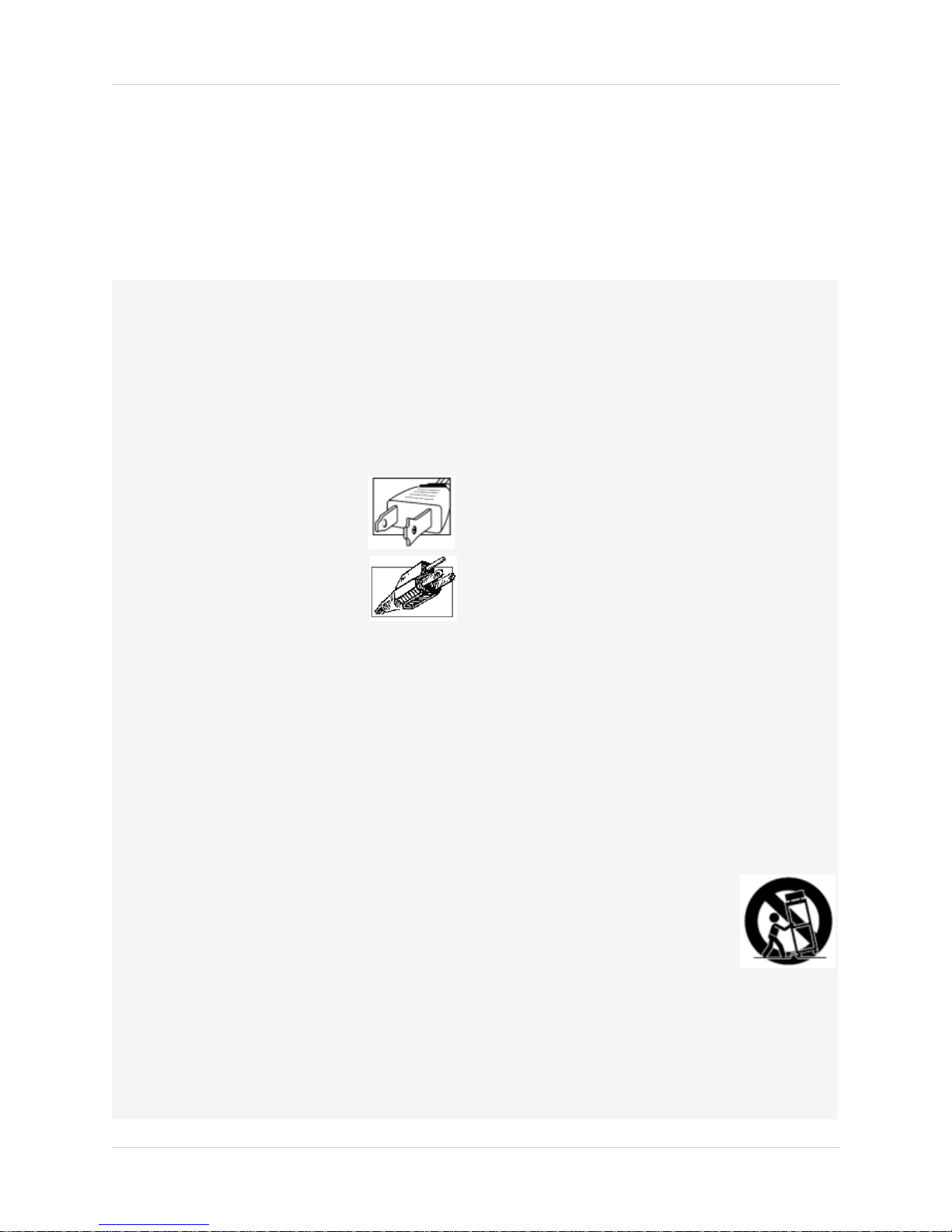
4. Polarization - Do not defeat the
safety purpose of the polarized or
grounding-type plug.
A polarized plug has two blades
with one wider than the other.
A grounding type plug has two
blades and a third grounding prong.
The wide blade or the third prong
are provided for your safety.
If the provided plug does not fit into your outlet,
consult an electrician for replacement of the
obsolete outlet.
5. Power Sources - This video product should be
operated only from the type of power source
indicated on the marking label. If you are not sure of
the type of power supply to your location, consult
your video dealer or local power company. For video
products intended to operate from battery power, or
other sources, refer to the operating instructions.
6. Overloading - Do not overload wall outlets of
extension cords as this can result in the risk of fire
or electric shock. Overloaded AC outlets, extension
cords, frayed power cords, damaged or cracked wire
insulation, and broken plugs are dangerous. They
may result in a shock or fire hazard. Periodically
examine the cord, and if its appearance indicates
damage or deteriorated insulation, have it replaced
by your service technician.
7. Power Cord Protection - Power supply cords should
be routed so that they are not likely to be walked on
or pinched by items placed upon or against them,
paying particular attention to cords at plugs,
convenience receptacles, and the point where they
exit from the video product.
8. Ventilation - Slots and openings in the case are
provided for ventilation to ensure reliable operation
of the video product and to protect it from
overheating. These openings must not be blocked or
covered. The openings should never be blocked by
placing the video equipment on a bed, sofa, rug, or
other similar surface. This video product should
never be placed near or over a radiator or heat
register. This video product should not be placed in a
built-in installation such as a bookcase or rack
unless proper ventilation is provided or the video
product manufacturer’s instructions have been
followed.
9. Attachments - Do not use attachments unless
recommended by the video product manufacturer as
they may cause a hazard.
10. Camera Extension Cables – Check the rating of
your extension cable(s) to verify compliance with
your local authority regulations prior to installation.
11. Water and Moisture - Do not use this video product
near water. For example, near a bath tub, wash
bowl, kitchen sink or laundry tub, in a wet
basement, near a swimming pool and the like.
Caution
operated equipment or accessories connected to
this unit should bear the UL listing mark of CSA
certification mark on the accessory itself and should
not be modified so as to defeat the safety features.
This will help avoid any potential hazard from
electrical shock or fire. If in doubt, contact qualified
service personnel.
12. Accessories - Do not place this
video equipment on an unstable
cart, stand, tripod, or table. The
video equipment may fall, causing
serious damage to the video
product. Use this video product
only with a cart, stand, tripod,
bracket, or table recommended by the
manufacturer or sold with the video product. Any
mounting of the product should follow the
manufacturer’s instructions and use a mounting
accessory recommended by the manufacturer.
: Maintain electrical safety. Powerline
iii
Page 8

Service
13. Servicing - Do not attempt to service this video
equipment yourself as opening or removing covers
may expose you to dangerous voltage or other
hazards. Refer all servicing to qualified service
personnel.
14. Conditions Requiring Service - Unplug this video
product from the wall outlet and refer servicing to
qualified service personnel under the following
conditions:
• When the power supply cord or plug is damaged.
• If liquid has been spilled or objects have fallen into
the video product.
• If the video product has been exposed to rain or
water.
• If the video product does not operate normally by
following the operating instructions. Adjust only
those controls that are covered by the operating
instructions. Improper adjustment of other controls
may result in damage and will often require
extensive work by a qualified technician to restore
the video product to its normal operation.
• If the video product has been dropped or the cabinet
has been damaged.
• When the video product exhibits a distinct change
in performance. This indicates a need for service.
Use
19. Cleaning - Unplug the video product from the wall
outlet before cleaning. Do not use liquid cleaners or
aerosol cleaners. Use a damp cloth for cleaning.
20. Product and Cart Combination - Video and cart
combination should be moved with care. Quick
stops, excessive force, and uneven surfaces may
cause the video product and car combination to
overturn.
21. Object and Liquid Entry - Never push objects for
any kind into this video product through openings as
they may touch dangerous voltage points or
“short-out” parts that could result in a fire or
electric shock. Never spill liquid of any kind on the
video product.
22. Lightning - For added protection for this video
product during a lightning storm, or when it is left
unattended and unused for long periods of time,
unplug it from the wall outlet and disconnect the
antenna or cable system. This will prevent damage
to the video product due to lightning and power line
surges.
15. Replacement Parts - When replacement parts are
required, have the service technician verify that the
replacements used have the same safety
characteristics as the original parts. Use of
replacements specified by the video product
manufacturer can prevent fire, electric shock or
other hazards.
16. Safety Check - Upon completion of any service or
repairs to this video product, ask the service
technician to perform safety checks recommended
by the manufacturer to determine that the video
product is in safe operating condition.
17. Wall or Ceiling Mounting - The cameras provided
with this system should be mounted to a wall or
ceiling only as instructed in this guide, using the
provided mounting brackets.
18. Heat - The product should be situated away from
heat sources such as radiators, heat registers,
stoves, or other products (including amplifiers) that
produce heat.
iv
Page 9

General Precautions
FCC CLASS B NOTICE
Note
This equipment has been tested and found to comply with the limits for a Class B digital device, pursuant to
Part 15 of the FCC Rules. These limits are designed to provide reasonable protection against harmful
interference in a residential installation. This equipment generates, uses, and can radiate radio frequency
energy and, if not in-stalled and used in accordance with the instruction, may cause harmful interference to
radio communications.
However, there is no guarantee that interference will not occur in a particular installation. If this equipment
does cause harmful interference to radio or television reception (which can be determined by turning the
equipment on and off), the user is encouraged to try to correct the interference by one or more of the following
measures:
• Reorient or relocate the receiving antenna
• Increase the separation between the equipment and receiver
• Connect the equipment into an outlet on a circuit different from that to which the receiver is
connected
• Consult the dealer or an experienced radio or television technician for assistance
1. All warnings and instructions in this manual should be followed.
2. Remove the plug from the outlet before cleaning.
water dampened cloth for cleaning.
3. Do not use this unit in humid or wet places.
4. Keep enough space around the unit for ventilation. Slots and openings in the storage cabinet
should
not be blocked.
5. During lightning storms, or when the unit is not used for a long time, disconnect the power
suppl
y, antenna, and cables to protect the unit from electrical surge.
Do not use liquid aerosol detergents. Use a
This equipment has been certified and found to comply with the limits regulated by FCC, EMC, and
LVD. There
fore, it is designated to provide reasonable protection against interference and will not
cause interference with other appliance usage.
However, it is imperative that the user follows this manuals guideline
to avoid improper usage
which may result in damage to the unit, electrical shock and fire hazard injury
In order to improve the feature functions and quality of this product,
the specifications are subject
to change without notice from time to time.
v
Page 10

INDUSTRY CANADA STATEMENT
This device complies with RSS-210 of the Industry Canada Rules. Operation is
subject to the following two conditions:
1. This device may not cause interference.
2. This device must accept any interference, including interference that may cause
undesired operation of the device.
This device has been designed to operate with an antenna having a maximum gain of
2.17 dBi.
Antenna having a higher gain is strictly prohibited per regulations of Industry
Canada. The required antenna impedance is 50 ohms.
To reduce potential radio interference to other users, the antenna type and its gain
should be so chosen that the EIRP is not more than required for successful
communication.
IMPORTANT NOTE:
IC Radiation Exposure Statement:
This equipment complies with IC radiation exposure limits set forth for an
uncontrolled environment. This equipment should be installed and operated with
minimum distance 20 cm between the radiator & your body.
vi
Page 11

LNE1001 Features
• Wired connectivity
®
• Remote Easy Connect (Yoics™ and MSN
• 10x digital zoom
• Supports VGA (640x480) resolution, 30 frames per second (real
time)
• Web browser support: Internet Explorer, Firefox, Safari for
viewing on PC or Mac
• Supports MJPEG
• MPEG4 enhanced compression for efficient video streaming
• Motion event triggers e-mail notification with JPEG image attachment
• Two-way audio via integrated microphone and external speakers (not included)
• 6 channel surveillance application for real time viewing and recording
• Free LOREX DDNS included for remote connection
)
• Secure web management connectivity (password protected)
• Professional grade camera (HTTP event – camera can trigger or be triggered by other LOREX
camera)
• Windows
• iPhone
®
7 compatible
®
and iPad® connectivity
vii
Page 12

LNE3003 Features
• Wired / Wireless IEEE 802.11b/g connectivity for
flexible installation
• Remote Easy Connect (Yoics and MSN)
• 10x Digital Zoom
• Superior low-light performance with
night-vision LEDs
• Supports VGA (640x480) resolution, 30 frames
per second (real time)
• Web browser support: Internet Explorer,
Firefox, Safari, for viewing on PC or Mac
• Supports MJPEG
• MPEG4 enhanced compression for efficient
video streaming
• Motion event triggers e-mail notification with JPEG image attachment
• Two-way audio via integrated microphone and external speakers (not included)
• 6 channel surveillance application for real time viewing and recording
• Free LOREX DDNS included for guaranteed connection
• Secure web management User/Password protection
®
• Windows
• iPhone
7 compatible
®
and iPad® connectivity
viii
Page 13

LNE4001 Features
• Wired/wireless 802.11b/g connectivity for flexible
installation
• Professional grade camera (HTTP Event – camera
can trigger or be triggered by other LOREX camera)
• Pan tilt control via iPhone
• Preset pan tilt tour
• Night vision - 30ft (10m), IR LEDs
• Remote easy connect (Yoics and MSN)
• Secure web management connectivity (password
protected)
• 10 x digital zoom
• MPEG4 enhanced compression for efficient video streaming
• 6-channel surveillance application for viewing and archiving
• Two-way audio via audio input/output (external microphone/speakers needed)
• Crystal clear video quality in VGA (640x480) resolution @ 30 frames per second
• Supports common browsers (Internet Explorer, Firefox, Safari) to be viewed using PC or Mac
• Alarm input/output (camera can be integrated with an alarm system—alarm triggers camera/
motion triggers alarm)
• Motion event triggers e-mail notification with JPEG attachment
• Windows
• iPhone
Windows Vista is a registered trademark of Microsoft Corporation. iPhone and iPod touch are registered trademarks of Apple, Inc. Other
trademarks are the property of Lorex Technology Inc. We reserve the right to change models, configurations or specifications without
notice or liability. Product may not be exactly as shown.
®
7 compatible
®
and iPad® connectivity
ix
Page 14

x
Page 15

TABLE OF CONTENTS
Getting Started . . . . . . . . . . . . . . . . . . . . . . . . . . . . . . . . . . . . . . . . . . . . . . . . . 1
System Requirements . . . . . . . . . . . . . . . . . . . . . . . . . . . . . . . . . . . . . . . . . . . 2
Additional Requirements . . . . . . . . . . . . . . . . . . . . . . . . . . . . . . . . . . . . . . . . . . . . . . . . . . 2
About Yoics . . . . . . . . . . . . . . . . . . . . . . . . . . . . . . . . . . . . . . . . . . . . . . . . . . . . . . . . . . . . . 2
Camera Overview . . . . . . . . . . . . . . . . . . . . . . . . . . . . . . . . . . . . . . . . . . . . . . . 3
LNE1001 Wired, Easy-Connect Internet Camera . . . . . . . . . . . . . . . . . . . . . . . . . . . . . . 3
LNE3003 Wired/Wireless, Day/Night, East-Connect Internet Camera . . . . . . . . . . . . 4
LNZ4001 Wired/Wireless, Day/Night, Pan/Tilt, Easy-Connect Internet Camera . . . . 5
Rear Panel . . . . . . . . . . . . . . . . . . . . . . . . . . . . . . . . . . . . . . . . . . . . . . . . . . . . . 6
LNE1001 . . . . . . . . . . . . . . . . . . . . . . . . . . . . . . . . . . . . . . . . . . . . . . . . . . . . . . . . . . . . . . . 6
LNE3003 Series . . . . . . . . . . . . . . . . . . . . . . . . . . . . . . . . . . . . . . . . . . . . . . . . . . . . . . . . .6
LNZ4001 . . . . . . . . . . . . . . . . . . . . . . . . . . . . . . . . . . . . . . . . . . . . . . . . . . . . . . . . . . . . . . . 7
Setting Up the Camera . . . . . . . . . . . . . . . . . . . . . . . . . . . . . . . . . . . . . . . . . . . 8
Positioning The Camera. . . . . . . . . . . . . . . . . . . . . . . . . . . . . . . . . . . . . . . . . . 9
Installation Warnings . . . . . . . . . . . . . . . . . . . . . . . . . . . . . . . . . . . . . . . . . . . . . . . . . . . . . 9
Night Vision . . . . . . . . . . . . . . . . . . . . . . . . . . . . . . . . . . . . . . . . . . . . . . . . . . . . . . . . . . . . . 9
Mounting the Camera. . . . . . . . . . . . . . . . . . . . . . . . . . . . . . . . . . . . . . . . . . . 10
Connecting the Camera . . . . . . . . . . . . . . . . . . . . . . . . . . . . . . . . . . . . . . . . . 11
Configuring the Camera. . . . . . . . . . . . . . . . . . . . . . . . . . . . . . . . . . . . . . . . . 12
Opening DigiConsole . . . . . . . . . . . . . . . . . . . . . . . . . . . . . . . . . . . . . . . . . . . . . . . . . . . . 12
Finding Your Camera as an UPnP Device (optional) . . . . . . . . . . . . . . . . . . . . . . . . . . . 13
Viewing Your Camera Using a Mac . . . . . . . . . . . . . . . . . . . . . . . . . . . . . . . . . . . . . . . . . 14
Using The Camera. . . . . . . . . . . . . . . . . . . . . . . . . . . . . . . . . . . . . . . . . . . . . . 15
About DigiViewer . . . . . . . . . . . . . . . . . . . . . . . . . . . . . . . . . . . . . . . . . . . . . . . . . . . . . . . 15
Setting Up Local Viewing . . . . . . . . . . . . . . . . . . . . . . . . . . . . . . . . . . . . . . . . . . . . . . . . . 16
Adjusting Focus . . . . . . . . . . . . . . . . . . . . . . . . . . . . . . . . . . . . . . . . . . . . . . . . . . . . . . . .17
Controlling PTZ . . . . . . . . . . . . . . . . . . . . . . . . . . . . . . . . . . . . . . . . . . . . . . . . 18
LNZ4001 . . . . . . . . . . . . . . . . . . . . . . . . . . . . . . . . . . . . . . . . . . . . . . . . . . . . . . . . . . . . . . . . . . . . . . . . . . . . 18
Presets, Tours, and Patrols . . . . . . . . . . . . . . . . . . . . . . . . . . . . . . . . . . . . . . . . . . . . . . 20
A: Setting Presets . . . . . . . . . . . . . . . . . . . . . . . . . . . . . . . . . . . . . . . . . . . . . . . . . . . . . . . . . . . . . . . . . . . . . . . . . . . .20
B: Customizing Tours . . . . . . . . . . . . . . . . . . . . . . . . . . . . . . . . . . . . . . . . . . . . . . . . . . . . . . . . . . . . . . . . . . . . . . . . .21
C: Using Patrols . . . . . . . . . . . . . . . . . . . . . . . . . . . . . . . . . . . . . . . . . . . . . . . . . . . . . . . . . . . . . . . . . . . . . . . . . . . . .23
Using Yoics. . . . . . . . . . . . . . . . . . . . . . . . . . . . . . . . . . . . . . . . . . . . . . . . . . . . 24
Registering with Yoics . . . . . . . . . . . . . . . . . . . . . . . . . . . . . . . . . . . . . . . . . . . . . . . . . . . 24
Registering Your Camera . . . . . . . . . . . . . . . . . . . . . . . . . . . . . . . . . . . . . . . . . . . . . . . . 25
Removing a Camera from Yoics . . . . . . . . . . . . . . . . . . . . . . . . . . . . . . . . . . . . . . . . . . . 27
xi
Page 16

Remote Viewing Using a Web Browser . . . . . . . . . . . . . . . . . . . . . . . . . . . . . . . . . . . . . 29
Setting Up Wireless Connectivity . . . . . . . . . . . . . . . . . . . . . . . . . . . . . . . . . . . . . . . . . . 30
Remote Viewing Using MSN Messenger . . . . . . . . . . . . . . . . . . . . . . . . . . . 31
Creating an MSN Account . . . . . . . . . . . . . . . . . . . . . . . . . . . . . . . . . . . . . . . . . . . . . . . . 31
Download and Install Messenger . . . . . . . . . . . . . . . . . . . . . . . . . . . . . . . . . . . . . . . . . . . . . . . . . . . . . . . 31
Configuring MSN Messenger on Your Camera . . . . . . . . . . . . . . . . . . . . . . . . . . . . . . . 32
Configuring MSN Messenger . . . . . . . . . . . . . . . . . . . . . . . . . . . . . . . . . . . . . . . . . . . . .33
Can’t See the Video? . . . . . . . . . . . . . . . . . . . . . . . . . . . . . . . . . . . . . . . . . . . . . . . . . . . . . . . . . . . . . . . . . . 34
Remote Viewing Using iPhone, iPod touch & iPad . . . . . . . . . . . . . . . . . . . 35
Downloading the App . . . . . . . . . . . . . . . . . . . . . . . . . . . . . . . . . . . . . . . . . . . . . . . . . . . . . . . . . . . . . . . . . . . . . . . . .35
Remote Viewing using the iPhone/ iPod Touch/ iPad . . . . . . . . . . . . . . . . . . . . . . . . . . . . . . . . . . . . . . . 35
Adding a Camera . . . . . . . . . . . . . . . . . . . . . . . . . . . . . . . . . . . . . . . . . . . . . . . . . . . . . . . . . . . . . . . . . . . . . 36
Using Lorex Live 2 / Lorex iMobile . . . . . . . . . . . . . . . . . . . . . . . . . . . . . . . . . . . . . . . . . . . . . . . . . . . . . . 36
Single Channel View . . . . . . . . . . . . . . . . . . . . . . . . . . . . . . . . . . . . . . . . . . . . . . . . . . . . . . . . . . . . . . . . . . . . . . . . . .36
Full Screen View . . . . . . . . . . . . . . . . . . . . . . . . . . . . . . . . . . . . . . . . . . . . . . . . . . . . . . . . . . . . . . . . . . . . . . . . . . . . . 37
Flip View . . . . . . . . . . . . . . . . . . . . . . . . . . . . . . . . . . . . . . . . . . . . . . . . . . . . . . . . . . . . . . . . . . . . . . . . . . . . . . . . . . .37
Mirror View . . . . . . . . . . . . . . . . . . . . . . . . . . . . . . . . . . . . . . . . . . . . . . . . . . . . . . . . . . . . . . . . . . . . . . . . . . . . . . . . . 37
Deleting a camera . . . . . . . . . . . . . . . . . . . . . . . . . . . . . . . . . . . . . . . . . . . . . . . . . . . . . . . . . . . . . . . . . . . . 37
Quick Delete (Optional) . . . . . . . . . . . . . . . . . . . . . . . . . . . . . . . . . . . . . . . . . . . . . . . . . . . . . . . . . . . . . . . . . . . . . . . .37
Advanced Controls . . . . . . . . . . . . . . . . . . . . . . . . . . . . . . . . . . . . . . . . . . . . . . . . . . . . . . . . . . . . . . . . . . . 38
Controlling Multiple Cameras . . . . . . . . . . . . . . . . . . . . . . . . . . . . . . . . . . . . . . . . . . . . . . . . . . . . . . . . . . . . . . . . . . 38
Multiple View . . . . . . . . . . . . . . . . . . . . . . . . . . . . . . . . . . . . . . . . . . . . . . . . . . . . . . . . . . . . . . . . . . . . . . . . . . . . . . . . 38
Scroll View . . . . . . . . . . . . . . . . . . . . . . . . . . . . . . . . . . . . . . . . . . . . . . . . . . . . . . . . . . . . . . . . . . . . . . . . . . . . . . . . . .38
Pan/Tilt Controls . . . . . . . . . . . . . . . . . . . . . . . . . . . . . . . . . . . . . . . . . . . . . . . . . . . . . . . . . . . . . . . . . . . . . 39
Advanced Settings . . . . . . . . . . . . . . . . . . . . . . . . . . . . . . . . . . . . . . . . . . . . . . . . . . . . . . . . . . . . . . . . . . . . 39
Changing streaming protocols (Advanced) . . . . . . . . . . . . . . . . . . . . . . . . . . . . . . . . . . . . . . . . . . . . . . . . 40
Troubleshooting . . . . . . . . . . . . . . . . . . . . . . . . . . . . . . . . . . . . . . . . . . . . . . . . . . . . . . . . . . . . . . . . . . . . . 41
DigiConsole . . . . . . . . . . . . . . . . . . . . . . . . . . . . . . . . . . . . . . . . . . . 43
About DigiConsole . . . . . . . . . . . . . . . . . . . . . . . . . . . . . . . . . . . . . . . . . . . . . . . . . . . . . . 43
System Requirements . . . . . . . . . . . . . . . . . . . . . . . . . . . . . . . . . . . . . . . . . . . . . . . . . . . 43
Using DigiConsole. . . . . . . . . . . . . . . . . . . . . . . . . . . . . . . . . . . . . . . . . . . . . . 44
Home . . . . . . . . . . . . . . . . . . . . . . . . . . . . . . . . . . . . . . . . . . . . . . . . . . . . . . . . . . . . . . . . . 44
Find . . . . . . . . . . . . . . . . . . . . . . . . . . . . . . . . . . . . . . . . . . . . . . . . . . . . . . . . . . . . . . . . . .45
Find Menu Options . . . . . . . . . . . . . . . . . . . . . . . . . . . . . . . . . . . . . . . . . . . . . . . . . . . . . . . . . . . . . . . . . . . 45
Open device in browser . . . . . . . . . . . . . . . . . . . . . . . . . . . . . . . . . . . . . . . . . . . . . . . . . . . . . . . . . . . . . . . . . . . . . . .45
View Live Image . . . . . . . . . . . . . . . . . . . . . . . . . . . . . . . . . . . . . . . . . . . . . . . . . . . . . . . . . . . . . . . . . . . . . . . . . . . . .46
Refresh list of devices . . . . . . . . . . . . . . . . . . . . . . . . . . . . . . . . . . . . . . . . . . . . . . . . . . . . . . . . . . . . . . . . . . . . . . . . 46
Live Video Options . . . . . . . . . . . . . . . . . . . . . . . . . . . . . . . . . . . . . . . . . . . . . . . . . . . . . . . . . . . . . . . . . . . . 47
Open device in browser . . . . . . . . . . . . . . . . . . . . . . . . . . . . . . . . . . . . . . . . . . . . . . . . . . . . . . . . . . . . . . . . . . . . . . .47
Stop Live Video . . . . . . . . . . . . . . . . . . . . . . . . . . . . . . . . . . . . . . . . . . . . . . . . . . . . . . . . . . . . . . . . . . . . . . . . . . . . . . 47
Record Video Image . . . . . . . . . . . . . . . . . . . . . . . . . . . . . . . . . . . . . . . . . . . . . . . . . . . . . . . . . . . . . . . . . . . . . . . . . .47
Mute Audio From Camera . . . . . . . . . . . . . . . . . . . . . . . . . . . . . . . . . . . . . . . . . . . . . . . . . . . . . . . . . . . . . . . . . . . . . 47
Enable microphone . . . . . . . . . . . . . . . . . . . . . . . . . . . . . . . . . . . . . . . . . . . . . . . . . . . . . . . . . . . . . . . . . . . . . . . . . . . 48
Full-screen Mode . . . . . . . . . . . . . . . . . . . . . . . . . . . . . . . . . . . . . . . . . . . . . . . . . . . . . . . . . . . . . . . . . . . . . . . . . . . .48
Refresh the list of devices . . . . . . . . . . . . . . . . . . . . . . . . . . . . . . . . . . . . . . . . . . . . . . . . . . . . . . . . . . . . . . . . . . . . .48
Register . . . . . . . . . . . . . . . . . . . . . . . . . . . . . . . . . . . . . . . . . . . . . . . . . . . . . . . . . . . . . . . . . . . . . . . . . . . . 48
Installing DigiConsole . . . . . . . . . . . . . . . . . . . . . . . . . . . . . . . . . . . . . . . . . . 49
xii
Page 17

Uninstalling DigiConsole . . . . . . . . . . . . . . . . . . . . . . . . . . . . . . . . . . . . . . . . 50
Recording Live Video . . . . . . . . . . . . . . . . . . . . . . . . . . . . . . . . . . . . . . . . . . . 51
Playing Recorded Video . . . . . . . . . . . . . . . . . . . . . . . . . . . . . . . . . . . . . . . . . 52
DigiViewer . . . . . . . . . . . . . . . . . . . . . . . . . . . . . . . . . . . . . . . . . . . . 53
About DigiViewer . . . . . . . . . . . . . . . . . . . . . . . . . . . . . . . . . . . . . . . . . . . . . . . . . . . . . . . 53
Opening DigiViewer . . . . . . . . . . . . . . . . . . . . . . . . . . . . . . . . . . . . . . . . . . . . 54
DigiConsole . . . . . . . . . . . . . . . . . . . . . . . . . . . . . . . . . . . . . . . . . . . . . . . . . . . . . . . . . . . . . . . . . . . . . . . . . . . . . . . . .54
Web browser . . . . . . . . . . . . . . . . . . . . . . . . . . . . . . . . . . . . . . . . . . . . . . . . . . . . . . . . . . . . . . . . . . . . . . . . . . . . . . . . 54
Surveillance . . . . . . . . . . . . . . . . . . . . . . . . . . . . . . . . . . . . . . . . . . . . . . . . . . 55
User . . . . . . . . . . . . . . . . . . . . . . . . . . . . . . . . . . . . . . . . . . . . . . . . . . . . . . . . . . . . . . . . . . 55
Main Display Screen . . . . . . . . . . . . . . . . . . . . . . . . . . . . . . . . . . . . . . . . . . . . . . . . . . . . . 55
Main Menu . . . . . . . . . . . . . . . . . . . . . . . . . . . . . . . . . . . . . . . . . . . . . . . . . . . . . . . . . . . . . 56
Advanced Controls Tool Panel . . . . . . . . . . . . . . . . . . . . . . . . . . . . . . . . . . . . . . . . . . . . 56
Audio . . . . . . . . . . . . . . . . . . . . . . . . . . . . . . . . . . . . . . . . . . . . . . . . . . . . . . . . . . . . . . . . . 56
Still Image Capture Button . . . . . . . . . . . . . . . . . . . . . . . . . . . . . . . . . . . . . . . . . . . . . . . 56
Advanced Controls Toolbar . . . . . . . . . . . . . . . . . . . . . . . . . . . . . . . . . . . . . . . . . . . . . . . 57
Channel Display . . . . . . . . . . . . . . . . . . . . . . . . . . . . . . . . . . . . . . . . . . . . . . . . . . . . . . . . . . . . . . . . . . . . . 57
PTZ . . . . . . . . . . . . . . . . . . . . . . . . . . . . . . . . . . . . . . . . . . . . . . . . . . . . . . . . . . . . . . . . . . . . . . . . . . . . . . . . 57
Picture . . . . . . . . . . . . . . . . . . . . . . . . . . . . . . . . . . . . . . . . . . . . . . . . . . . . . . . . . . . . . . . . . . . . . . . . . . . . . 57
Rotate Image . . . . . . . . . . . . . . . . . . . . . . . . . . . . . . . . . . . . . . . . . . . . . . . . . . . . . . . . . . . . . . . . . . . . . . . . 57
Live Image . . . . . . . . . . . . . . . . . . . . . . . . . . . . . . . . . . . . . . . . . . . . . . . . . . . . . . . . . . . . . 57
Recording Video (PC only, using Internet Explorer) . . . . . . . . . . . . . . . . . . . . . . . . . . . . . . . . . . . . . . . . . 58
Adding Digiviewer as a Trusted Site . . . . . . . . . . . . . . . . . . . . . . . . . . . . . . . . . . . . . . . . . . . . . . . . . . . . . 59
Events. . . . . . . . . . . . . . . . . . . . . . . . . . . . . . . . . . . . . . . . . . . . . . . . . . . . . . . . 61
Motion Events . . . . . . . . . . . . . . . . . . . . . . . . . . . . . . . . . . . . . . . . . . . . . . . . . . . . . . . . . .61
HTTP Events . . . . . . . . . . . . . . . . . . . . . . . . . . . . . . . . . . . . . . . . . . . . . . . . . . . . . . . . . . . 62
Discovery . . . . . . . . . . . . . . . . . . . . . . . . . . . . . . . . . . . . . . . . . . . . . . . . . . . . . . . . . . . . . . 63
UPnP . . . . . . . . . . . . . . . . . . . . . . . . . . . . . . . . . . . . . . . . . . . . . . . . . . . . . . . . . . . . . . . . . . . . . . . . . . . . . . 63
Preset . . . . . . . . . . . . . . . . . . . . . . . . . . . . . . . . . . . . . . . . . . . . . . . . . . . . . . . . . . . . . . . .64
Home Position . . . . . . . . . . . . . . . . . . . . . . . . . . . . . . . . . . . . . . . . . . . . . . . . . . . . . . . . . . . . . . . . . . . . . . . 65
Patrol Control . . . . . . . . . . . . . . . . . . . . . . . . . . . . . . . . . . . . . . . . . . . . . . . . . . . . . . . . . . 66
Alarm Input/Output . . . . . . . . . . . . . . . . . . . . . . . . . . . . . . . . . . . . . . . . . . . . . . . . . . . . . 67
Alarm Input . . . . . . . . . . . . . . . . . . . . . . . . . . . . . . . . . . . . . . . . . . . . . . . . . . . . . . . . . . . . . . . . . . . . . . . . . 67
Alarm Output . . . . . . . . . . . . . . . . . . . . . . . . . . . . . . . . . . . . . . . . . . . . . . . . . . . . . . . . . . . . . . . . . . . . . . . . 68
Settings . . . . . . . . . . . . . . . . . . . . . . . . . . . . . . . . . . . . . . . . . . . . . . . . . . . . . . 69
Preferences . . . . . . . . . . . . . . . . . . . . . . . . . . . . . . . . . . . . . . . . . . . . . . . . . . . . . . . . . . . 70
Device Description . . . . . . . . . . . . . . . . . . . . . . . . . . . . . . . . . . . . . . . . . . . . . . . . . . . . . . . . . . . . . . . . . . . 70
On Screen Display . . . . . . . . . . . . . . . . . . . . . . . . . . . . . . . . . . . . . . . . . . . . . . . . . . . . . . . . . . . . . . . . . . . . 70
Lighting . . . . . . . . . . . . . . . . . . . . . . . . . . . . . . . . . . . . . . . . . . . . . . . . . . . . . . . . . . . . . . . . . . . . . . . . . . . . 71
Device Setup . . . . . . . . . . . . . . . . . . . . . . . . . . . . . . . . . . . . . . . . . . . . . . . . . . . . . . . . . . . 71
Local Network Settings . . . . . . . . . . . . . . . . . . . . . . . . . . . . . . . . . . . . . . . . . . . . . . . . . . . . . . . . . . . . . . . 71
System Clock . . . . . . . . . . . . . . . . . . . . . . . . . . . . . . . . . . . . . . . . . . . . . . . . . . . . . . . . . . . . . . . . . . . . . . . . 72
OPTIONAL: . . . . . . . . . . . . . . . . . . . . . . . . . . . . . . . . . . . . . . . . . . . . . . . . . . . . . . . . . . . . . . . . . . . . . . . . . . . . . . . . . .72
Network Configuration . . . . . . . . . . . . . . . . . . . . . . . . . . . . . . . . . . . . . . . . . . . . . . . . . . . . . . . . . . . . . . . . 73
xiii
Page 18

Remote Access . . . . . . . . . . . . . . . . . . . . . . . . . . . . . . . . . . . . . . . . . . . . . . . . . . . . . . . . .74
Yoics Instant Networking . . . . . . . . . . . . . . . . . . . . . . . . . . . . . . . . . . . . . . . . . . . . . . . . . . . . . . . . . . . . . . 74
MSN Messenger . . . . . . . . . . . . . . . . . . . . . . . . . . . . . . . . . . . . . . . . . . . . . . . . . . . . . . . . . . . . . . . . . . . . . 75
Dynamic DNS . . . . . . . . . . . . . . . . . . . . . . . . . . . . . . . . . . . . . . . . . . . . . . . . . . . . . . . . . . . . . . . . . . . . . . . . 75
Network Services . . . . . . . . . . . . . . . . . . . . . . . . . . . . . . . . . . . . . . . . . . . . . . . . . . . . . . . 76
Outgoing Email Server . . . . . . . . . . . . . . . . . . . . . . . . . . . . . . . . . . . . . . . . . . . . . . . . . . . . . . . . . . . . . . . . 76
Network Recorder Server . . . . . . . . . . . . . . . . . . . . . . . . . . . . . . . . . . . . . . . . . . . . . . . . . . . . . . . . . . . . . 77
Accounts . . . . . . . . . . . . . . . . . . . . . . . . . . . . . . . . . . . . . . . . . . . . . . . . . . . . . . . . . . . . . . 78
Current User Account . . . . . . . . . . . . . . . . . . . . . . . . . . . . . . . . . . . . . . . . . . . . . . . . . . . . . . . . . . . . . . . . . 78
General User Accounts . . . . . . . . . . . . . . . . . . . . . . . . . . . . . . . . . . . . . . . . . . . . . . . . . . . . . . . . . . . . . . . . 79
Anonymous Guest Account . . . . . . . . . . . . . . . . . . . . . . . . . . . . . . . . . . . . . . . . . . . . . . . . . . . . . . . . . . . . 79
Wireless . . . . . . . . . . . . . . . . . . . . . . . . . . . . . . . . . . . . . . . . . . . . . . . . . . . . . . . . . . . . . . 80
Wireless Settings . . . . . . . . . . . . . . . . . . . . . . . . . . . . . . . . . . . . . . . . . . . . . . . . . . . . . . . . . . . . . . . . . . . . 80
Channels . . . . . . . . . . . . . . . . . . . . . . . . . . . . . . . . . . . . . . . . . . . . . . . . . . . . . . . . . . . . . . 81
Remote Cameras and Video Servers . . . . . . . . . . . . . . . . . . . . . . . . . . . . . . . . . . . . . . . . . . . . . . . . . . . . . 81
System . . . . . . . . . . . . . . . . . . . . . . . . . . . . . . . . . . . . . . . . . . . . . . . . . . . . . . . . . . . . . . . . 82
Advanced Parameter Settings . . . . . . . . . . . . . . . . . . . . . . . . . . . . . . . . . . . . . . . . . . . . . . . . . . . . . . . . . . 82
Upgrading Firmware . . . . . . . . . . . . . . . . . . . . . . . . . . . . . . . . . . . . . . . . . . . . . . . . . . . . . . . . . . . . . . . . . . 84
System Log . . . . . . . . . . . . . . . . . . . . . . . . . . . . . . . . . . . . . . . . . . . . . . . . . . . 85
Help . . . . . . . . . . . . . . . . . . . . . . . . . . . . . . . . . . . . . . . . . . . . . . . . . . . . . . . . . 86
Appendix A: Camera Specifications . . . . . . . . . . . . . . . . . . . . . . . . . . . . . . . 87
LNE1001 . . . . . . . . . . . . . . . . . . . . . . . . . . . . . . . . . . . . . . . . . . . . . . . . . . . . . . . . . . . . . .87
LNE3003 . . . . . . . . . . . . . . . . . . . . . . . . . . . . . . . . . . . . . . . . . . . . . . . . . . . . . . . . . . . . . .88
LNZ4001 . . . . . . . . . . . . . . . . . . . . . . . . . . . . . . . . . . . . . . . . . . . . . . . . . . . . . . . . . . . . . . 89
Appendix B: Adding Cameras . . . . . . . . . . . . . . . . . . . . . . . . . . . . . . . . . . . . 90
Setting up Additional Cameras . . . . . . . . . . . . . . . . . . . . . . . . . . . . . . . . . . . . . . . . . . . . 90
Finding the Additional Cameras . . . . . . . . . . . . . . . . . . . . . . . . . . . . . . . . . . . . . . . . . . .90
Port Ranges . . . . . . . . . . . . . . . . . . . . . . . . . . . . . . . . . . . . . . . . . . . . . . . . . . . . . . . . . . . . . . . . . . . . . . . . . 91
Adding Cameras to DigiViewer . . . . . . . . . . . . . . . . . . . . . . . . . . . . . . . . . . . . . . . . . . . . 92
Viewing Cameras . . . . . . . . . . . . . . . . . . . . . . . . . . . . . . . . . . . . . . . . . . . . . . . . . . . . . . . 93
Appendix C: Network Connectivity . . . . . . . . . . . . . . . . . . . . . . . . . . . . . . . . 94
Locating the IP and MAC addresses . . . . . . . . . . . . . . . . . . . . . . . . . . . . . . . . . . . . . . . . 95
Appendix D: Router Port Forwarding. . . . . . . . . . . . . . . . . . . . . . . . . . . . . . 96
Appendix E: Auto Port Forwarding Wizard . . . . . . . . . . . . . . . . . . . . . . . . . 97
Installation . . . . . . . . . . . . . . . . . . . . . . . . . . . . . . . . . . . . . . . . . . . . . . . . . . . . . . . . . . . . 97
Obtaining Your Router Model Number and Version . . . . . . . . . . . . . . . . . . . . . . . . . . . . . . . . . . . . . . . . . . . . . . . .98
Example . . . . . . . . . . . . . . . . . . . . . . . . . . . . . . . . . . . . . . . . . . . . . . . . . . . . . . . . . . . . . . . . . . . . . . . . . . . . . . . . . . . .98
Configuration . . . . . . . . . . . . . . . . . . . . . . . . . . . . . . . . . . . . . . . . . . . . . . . . . . . . . . . . . . 99
Initial Startup: Select language . . . . . . . . . . . . . . . . . . . . . . . . . . . . . . . . . . . . . . . . . . . . . . . . . . . . . . . . . . . . . . . . .99
Step 1: Populate the router database . . . . . . . . . . . . . . . . . . . . . . . . . . . . . . . . . . . . . . . . . . . . . . . . . . . . . . . . . . . .99
Step 2: Enter your router settings . . . . . . . . . . . . . . . . . . . . . . . . . . . . . . . . . . . . . . . . . . . . . . . . . . . . . . . . . . . . . . 100
Step 3: Update the router settings . . . . . . . . . . . . . . . . . . . . . . . . . . . . . . . . . . . . . . . . . . . . . . . . . . . . . . . . . . . . . 101
Step 4: Test your connection . . . . . . . . . . . . . . . . . . . . . . . . . . . . . . . . . . . . . . . . . . . . . . . . . . . . . . . . . . . . . . . . . . 101
Configuring multiple routers . . . . . . . . . . . . . . . . . . . . . . . . . . . . . . . . . . . . . . . . . . . . . . . . . . . . . . . . . . . . . . . . . . 101
Scenario A: Router/Modem combination + Router . . . . . . . . . . . . . . . . . . . . . . . . . . . . . . . . . . . . . . . . . . . . . . . . 102
xiv
Page 19

Scearnio B: Multiple Routers . . . . . . . . . . . . . . . . . . . . . . . . . . . . . . . . . . . . . . . . . . . . . . . . . . . . . . . . . . . . . . . . . 102
Example . . . . . . . . . . . . . . . . . . . . . . . . . . . . . . . . . . . . . . . . . . . . . . . . . . . . . . . . . . . . . . . . . . . . . . . . . . . . . . . . . . .103
Appendix F: Setting Up DDNS Service . . . . . . . . . . . . . . . . . . . . . . . . . . . . 104
Configuring DDNS in DigiViewer . . . . . . . . . . . . . . . . . . . . . . . . . . . . . . . . . . . . . . . . . . 106
Appendix G: Connecting Alarm and Motion Devices . . . . . . . . . . . . . . . . 107
Appendix H: Remote Access with Internet Explorer . . . . . . . . . . . . . . . . 108
Internet Explorer Security Warnings . . . . . . . . . . . . . . . . . . . . . . . . . . . . . . . . . . . . . . 109
Appendix I: Setting Up HTTP Events. . . . . . . . . . . . . . . . . . . . . . . . . . . . . . 110
Example . . . . . . . . . . . . . . . . . . . . . . . . . . . . . . . . . . . . . . . . . . . . . . . . . . . . . . . . . . . . . . 110
Positioning the Cameras . . . . . . . . . . . . . . . . . . . . . . . . . . . . . . . . . . . . . . . . . . . . . . . . . . . . . . . . . . . . . 110
Setting a Preset . . . . . . . . . . . . . . . . . . . . . . . . . . . . . . . . . . . . . . . . . . . . . . . . . . . . . . . . . . . . . . . . . . . . . . . . . . . . 110
Entering HTTP Event Information . . . . . . . . . . . . . . . . . . . . . . . . . . . . . . . . . . . . . . . . . . . . . . . . . . . . . . . . . . . . . . 111
Result . . . . . . . . . . . . . . . . . . . . . . . . . . . . . . . . . . . . . . . . . . . . . . . . . . . . . . . . . . . . . . . . . . . . . . . . . . . . . 112
Appendix J: Rebooting, Resetting, and Recalibrating the Camera . . . . 113
Rebooting the Camera . . . . . . . . . . . . . . . . . . . . . . . . . . . . . . . . . . . . . . . . . . . . . . . . . . 113
Restoring Factory Defaults . . . . . . . . . . . . . . . . . . . . . . . . . . . . . . . . . . . . . . . . . . . . . .113
Resetting the Camera . . . . . . . . . . . . . . . . . . . . . . . . . . . . . . . . . . . . . . . . . . . . . . . . . . 114
Recalibrating the Camera . . . . . . . . . . . . . . . . . . . . . . . . . . . . . . . . . . . . . . . . . . . . . . . 114
Appendix K: Registering, Removing, and Resetting Yoics Services . . . 115
Registering Your Camera . . . . . . . . . . . . . . . . . . . . . . . . . . . . . . . . . . . . . . . . . . . . . . . 115
Removing Yoics Services . . . . . . . . . . . . . . . . . . . . . . . . . . . . . . . . . . . . . . . . . . . . . . . . 118
Removing Services Using DigiViewer . . . . . . . . . . . . . . . . . . . . . . . . . . . . . . . . . . . . . . . . . . . . . . . . . . . 119
Resetting Yoics Services . . . . . . . . . . . . . . . . . . . . . . . . . . . . . . . . . . . . . . . . . . . . . . . . 119
Troubleshooting Camera Registration . . . . . . . . . . . . . . . . . . . . . . . . . . . . . . . . . . . . 120
xv
Page 20

xvi
Page 21
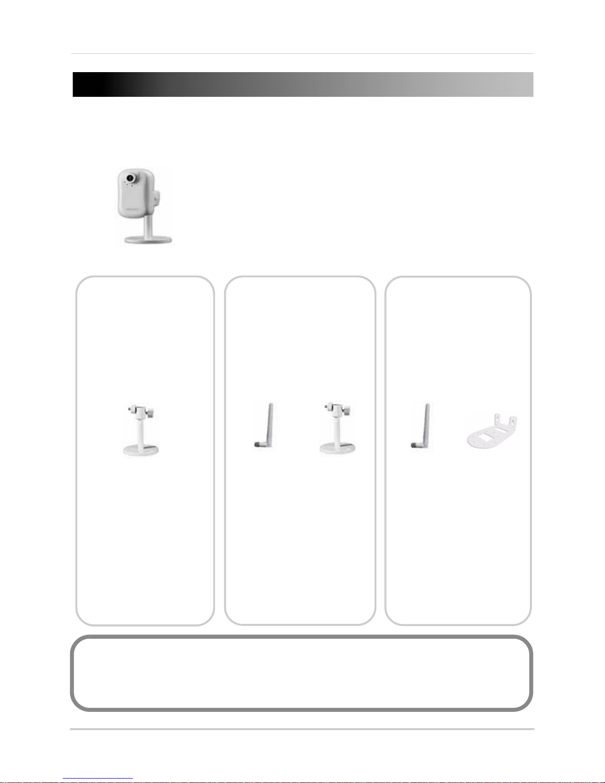
GETTING STARTED
LNE1001 LNE3003 LNZ4001
POWER SUPPLY
QUICKSTART GUIDE
DOCUMENTATION CD
MOUNTING KIT
MOUNTING STAND
ETHERNET CABLE
MOUNTING KIT
WIRELESS
ANTENNA
MOUNTING
STAND
WIRELESS
ANTENNA
MOUNTING
BRACKET
MOUNTING KIT
POWER SUPPLY
POWER SUPPLY
ETHERNET CABLE
QUICKSTART GUIDE
DOCUMENTATION CD
QUICKSTART GUIDE
DOCUMENTATION CD
The system comes with the following components:
ETHERNET CABLE
*CAMERA CONFIGURATION MAY VARY BY MODEL. PLEASE REFER TO YOUR PACKAGE FOR
SPECIFIC DETAILS.
CHECK YOUR PACKAGE TO CONFIRM THAT YOU HAVE RECEIVED THE COMPLETE SYSTEM,
INCLUDING ALL COMPONENTS SHOWN ABOVE.
1
Page 22

SYSTEM REQUIREMENTS
For setup and viewing, the camera requires the following:
• PC running Windows XP/Vista / 7
c OSX 10.4 or later (Viewing only)
• Ma
• Pentium 4 2.4 Ghz or above processor
• 1 GB of memory
• Internet connection
• Web browser: Internet Explorer 7 or later (with Active X), Mozilla Firefox, Safari
NOTE: If you are using a Mac, only certain functions are available on the camera. For details, see “Viewing
Your Camera Using a Mac” on page 14.
Additional Requirements
To view your camera from a remote computer (remote viewing using Yoics), you may need to
install the following:
®
• QuickTime
camera using Yoics. Download QuickTime at www
• QuickTime is also required for use with Web browser
Safari
About Yoics
7 or later: The QuickTime plug-in is required to view streaming video from your
.apple.com/quicktime/download
s other than Internet Explorer, i.e. Firefox,
Yoics is secure, instant networking made easy. This camera is designed to work with Yoics
easy-connect remote access, letting you connect to
www.yoics.com for
NOTE: This manu al re fers to the came ra operating using the Yoics Easy Connect Remote Access service.
Yoics Easy Connect Remote Access service is subject to improvements and changes made by Yoics.
more information on using Yoics.
your camera anywhere, anytime. Visit
2
Page 23
CAMERA OVERVIEW
1
2
3
4
5
6
LNE1001 Wired, Easy-Connect Internet Camera
1. Focus: Manually adjust the focus ring to sharpen the image.
2. Lens: 1/4"
3. Power LED
4. Network Indicator: Pulses blue du
5. Mi
6. Stand:
crophone: Built-in microphone for listen-in audio over the network.
lens with a CMOS image sensor.
Indicator: Lights up solid blue when camera is powered on.
Assembled support stand for the camera.
ring network access.
3
Page 24
Camera Overview
1
2
3
4
5
6
8
7
LNE3003 Wired/Wireless, Day/Night, East-Connect
Internet Camera
1. Focus: Manually adjust the focus ring to sharpen the image.
2. Lens: 1/4"
3. Power LED
4. Network Indicator: Pulses blue du
5. Mi
6. Stand:
7. Infrared LEDs: 6 whit
8. Wireless Antenn
4
crophone: Built-in microphone for listen-in audio over the network.
lens with a CMOS image sensor.
Indicator: Lights up solid blue when camera is powered on.
ring network access.
Assembled support stand for the camera.
e-light LEDs for night vision.
a: Removable wireless antenna.
Page 25
LNZ4001 Wired/Wireless, Day/Night, Pan/Tilt,
1
2
3
4
5
6
7
Easy-Connect Internet Camera
Camera Overview
1. Network Indicator: Pulses blue during network access.
2. Power LED
3. Mi
4. Infrared LEDs: 12
5. Focus: Man
6. Lens: 1/4"
7. Wireless Antenn
crophone: Built-in microphone for listen-in audio over the network.
Indicator: Lights up solid blue when camera is powered on.
IR LEDs for night vision.
ually adjust the focus ring to sharpen the image.
lens with a CMOS image sensor.
a: Removable wireless antenna.
5
Page 26
REAR PANEL
1
2
3
4
1
2
3 4
5
LNE1001
1. Speaker: 3.5 mm audio port for external speakers or other audio devices (not included).
2. Reset:
configuration.
3. LAN:
connect the other end of the network cable to a network router, switch, or active wall port.
4. DC
Using a paper-clip, hold for 10 seconds to reset the camera to its default
Network port. Connect one end of the included network cable to this port, and then
5V: Connect the 5V DC power adapter.
LNE3003 Series
1. DC 5V: Connect the 5V DC power adapter.
2. Reset:
configuration.
3. Speaker: 3.5 mm
4. LAN:
connect the other end of the network cable to a network router, switch, or active wall port.
5. Antenna Connection (SMA): Connect
Using a paper-clip, hold for 10 seconds to reset the camera to its default
audio port for external speakers or other audio devices (not included).
Network port. Connect one end of the included network cable to this port, and then
the wireless antenna—angle at 90°, 180°; rotate 360°.
6
Page 27
Rear Panel
1
2
3
4
5
6
7
LNZ4001
1. Antenna Connection (SMA): Connect the wireless antenna—angle at 90°, 180°; rotate 360°.
2. 12
3. Reset:
4. Audio I
5. Audio O
6. Ethernet: Ne
7. Alarm Bloc
VDC: Connect the 12V DC power adapter.
Using a paper-clip, hold for 10 seconds to reset the camera to its default
configuration.
n: 3.5 mm audio port for an external microphone (not included).
ut: 3.5 mm audio port for external speakers or other audio devices (not included).
twork port. Connect one end of the included network cable to this port, and then
connect the other end of the network cable to a network router, switch, or active wall port.
k: Connection block for external alarm/motion devices (not included).
7
Page 28
SETTING UP THE CAMERA
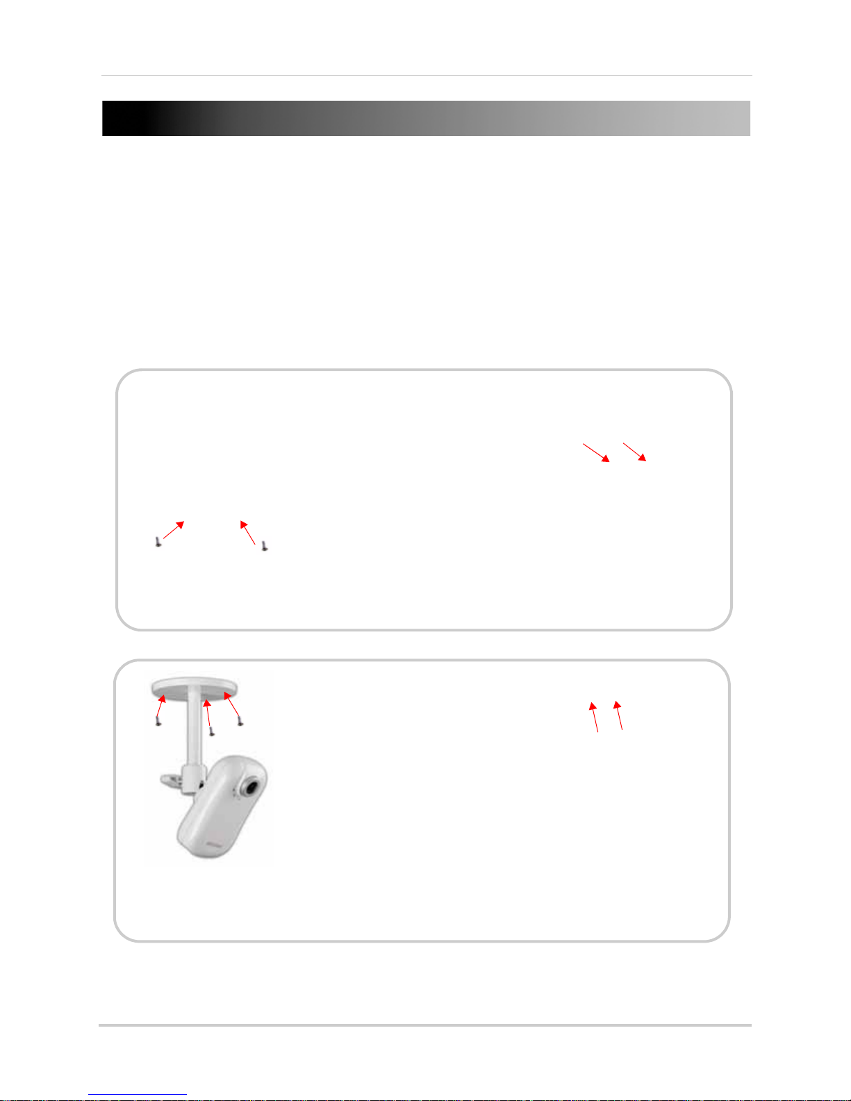
Figure 1.0 Assemble the pedestal
Figure 1.1 Attach pedestal to the camera
Figure 1.2 Attach the antenna to the
camera (LNE3003
/
LNZ4001
only
)
Figure 1.3 Fully assembled camera (from top-right, LNE1001,
LNZ4001, LNE3003)
Basic setup for your network camera.
NOTE: Pedestal assembly refers to LNE1001 and LNE3003 series
To set up the camera:
1. Attach the stand to the base
2. Attach the mounting bracket to the stand.
3. Attach the camera to the completed pedestal. Use the thumb screws to secure the camera
fi
rmly.
4. Attach the wireless antenna to the back of
the camera (LNE3003/LNZ4001 series
only
.
only
).
8
Page 29

POSITIONING THE CAMERA
Before you install the camera, carefully plan where and how it will be positioned.
Installation Warnings
• Select a location for the camera that provides a clear view of the area you want to monitor,
which is free from dust, and is not in line-of-sight to a strong light source or direct sunlight.
• Route the cables so that they are not close to power or telephone lines, transformers,
microwave ovens or other electrical equipment
• Select a location for the camera that has an ambient temperature between 32°F~113°F
(0°C~45°C); Humidity 20-80% relative humidity (non-condensing)
• If you plan to install the camera in a location that has conditions not recommended in this
manual, consult with a professional installer and consider use of a separate camera cover or
housing
• Before starting permanent installation, have another person hold the camera for you while
you verify its performance by observing the image on a monitor
Night Vision
The LNE3003 and LNZ4001 cameras include night
vision LEDs, which provide the camera with the ability
to view images in low light conditions. It is important to
use the provided power adaptor when using the camera
for prolonged
periods in low light conditions.
9
Page 30
MOUNTING THE CAMERA
Wall Mounting
Figure 2.0 Secure camera to bracket
(LNZ4001 Series only)
Figure 2.1 Secure camera and bracket to wall
(LNZ4001 Series)
Figure 2.2 Ceiling mounting
(LNE1001/LNE3003 Series)
Figure 2.3 Secure camera and bracket to ceiling
(LNZ4001 Series)
Ceiling Mounting
The camera can be mounted to walls, ceilings, desks, tables, or other flat surfaces.
To mount the camera to a wall or ceiling:
1. Select a location for the camera. Make sure you are able to drive screws into the surface. If
nec
essary, use the mounting bracket/pedestal to mark holes for drilling.
2. Use the small screws included in the mounting kit to secure the camera to the mounting
only
br
acket (LNZ4001
3. Use the large screws and anchors to secure the camera and bracket/pedestal to the
mounting su
rface (see figure 2.1).
; see figure 2.0).
10
Page 31

CONNECTING THE CAMERA
Figure 3.0 Wired connection (wired connection only needed for initial setup of wireless cameras)
Figure 3.1 Wireless connection
LNZ4001
LNE1001
LNE3003
LNZ4001
LAPTOP
PC
PC
With the camera assembled, you can now connect the power and network cables.
To connect the camera:
1. Connect the included Ethernet cable to the Ether
2. Connect the other end of the Ethernet cable to a network r
net port on the rear panel of the camera.
outer, switch, or active wall port.
NOTE: For a wireless connection, the camera only needs to be wired to your network for initial setup and
configuration. Once the camera is fully setup, you can disconnect the Ethernet cable and connect to your
network wirelessly.
3. Connect the power adapter to the camera.
4. Plug in the power adapter to a power outlet.
11
Page 32

CONFIGURING THE CAMERA
ATTENTION: Before starting the installation, please ensure your computer is connected to the
same local network as the camera and has access to the Internet.
Figure 4.0 DigiConsole main window
With the camera setup and connected, you can now set up local viewing, remote viewing, and
wireless connectivity.
NOTE: It is recommended to install the camera when your computer is wired to the local network. If you
are using the wireless connection on your computer, please connect your computer to your wireless
router using an Ethernet cable (not included).
NOTE: The
Opening DigiConsole
Use DigiConsole to setup your camera.
NOTE: Prior to using DigiConsole, visit www.lorextechnology.com and check for software and firmware
updates. Please refer to the DigiConsole & DigiViewer Software Manual for more information on
upgrading firmware.
To open DigiConsole:
following refers to an installation on Windows Vista. Some steps may differ in Windows XP.
1. Insert the included DigiConsole software CD int
o your CD/DVD-ROM drive. DigiConsole
automatically launches.
2. If a security pop-up window appears, click Unblock and Con
tinue to allow DigiConsole access
to the Internet.
NOTE: If Autorun fails to start, go to Computer (My Computer for Windows XP users) and double-click
the CD-drive to run the application. Follow step 2.
NOTE: Y
record and playback video, you must install DigiConsole to your computer. Please refer to the DigiConsole
& DigiViewer Software Manual for more information on installing DigiConsole.
ou do not need to install DigiConsole to view live video from the camera. However, if you wish to
12
Page 33

3. Click Find to discover Lorex cameras on your network.
Figure 4.1 Select your camera from the list of devices
Figure 4.2 Turn on Network discovery
Figure 4.3 Allow Network discovery
Figure 4.4 Find your camera as a UPnP device
NOTE: If using Windows XP/Vista/7,
it is highly recommended to use
Internet Explorer (PC version) as
your default browser.
Configuring the Camera
4. Double-click the selected camera to launch
5. At the prompt, enter your user name and password (by
on local viewing, see see “Setting Up Local
DigiViewer
in your default browser.
default, admin / admin). For details
Viewing” on page 16.
Finding Your Camera as an UPnP Device (optional)
You can also discover the camera as an UPnP (Universal Plug and Play) device by opening
Network in Vista (My Network Places for Windows XP users).
To discover your UPnP device:
1. Turn on Network discovery and file sharing t
2. Double-click the selected camera icon to launch DigiViewer in your default browser.
o find your camera as an UPnP device.
3. At the prompt, enter your user name and password (by
on local viewing, see “Setting Up Local Viewing” on page 16.
default, admin / admin). For details
13
Page 34

Configuring the Camera
Figure 5.0 DigiViewer in Safari using Mac OS X
Figure 5.1 Double-click your device from the Bonjour list
Figure 5.2 Your device may need to reconnect with the new wireless settings
Default Username: admin
Default Passwod: admin
Viewing Your Camera Using a Mac
If you are using one of the Lorex network cameras with a Mac, you can view your camera using the
Safari web browser.
NOTE: If using a Mac, you will not be able to record live video directly to your Mac.
To view your camera using a Mac:
1. Open Safari. Cl
2. Under Collections, select Bo
ick (Bookmarks button) in the Bookmarks bar.
njour. The Bonjour list opens.
3. Double-click your device from the Bonjour list.
4. Log in using your user name and password and select the box for Safari to remember your
sword. Click Log In. DigiViewer launches in the main Safari window.
pas
NOTE: Safari 4 has different security settings. To ensure login, please select this box if using Safari 4.
NOTE: F
page 24.
or details on viewing your camera from a remote location using a Mac, see “Using Yoics” on
14
Page 35

USING THE CAMERA
Figure 6.0 DigiViewer main screen
1
2
3 4 6
8
5
7
DigiConsole helps you setup and configure your camera. You will use
playback, and further camera configurations.
NOTE: For complete details on DigiViewer functions, see “DigiViewer” on page 53.
DigiViewer
for viewing,
About DigiViewer
DigiViewer is a browser-based remote surveillance software that lets you view, playback, record,
and configure your network camera from a remote location.
1. Main Me
Help.
2. Advanced Control Panel:
once activated from the Advanced Controls Toolbar the bottom of the main window.
3. Audio: Contr
4. Screenshot:
separate browser window. This still image can be saved as a JPG file.
5. Advanced Control Toolbar:
6. Play/Stop: St
7. Record:
8. Main Displ
nu: View or change configuration for Surveillance, Events, Settings, System Log, and
ols the audio on the camera.
Click to capture the currently displayed video image as a still image in a
art/stop the live image.
Record live video onto the local hard disk (Internet Explorer on the PC only).
ay Screen: View streaming live video from the camera in the main window.
Change channel displays, control PTZ cameras, or adjust picture
Adjust channel display, PTZ, Picture, and Rotate Image.
15
Page 36

Using The Camera
ATTENTION: For security reasons, you
should change the default username and
password (admin) for the camera. For
details on changing your user name and
password, see “Accounts” on page 78.
Figure 6.2 Windows Security/Firewall
Figure 6.3 Install ActiveX
Figure 6.1 Select ActiveX Install from the warning bar
Setting Up Local Viewing
With your camera now detected by DigiConsole, you can begin to view live images from your
camera on your local network. When using Internet Explorer, you need to install ActiveX in order
for DigiViewer to run properly; other supported browsers will require QuickTime.
To setup local viewing:
1. With DigiViewer open in your default browser, enter admin in the user
name text field and
admin in the password text field. If using Internet Explorer, you will be prompted to Install
ActiveX Control.
2. Click the warning bar and select Install
3. Click Unblock or Continue in a
ny subsequent security windows (this is only required for initial
Active X Control.
setup).
4. Click In
stall to start the installation. DigiViewer resets and live video streams in your
browser.
16
Page 37

Using The Camera
Figure 6.4 Manual focus ring (LNE3003 shown)
Adjusting Focus
You can manually adjust the focus of the camera.
NOTE: Make sure the camera is powered on and connected to a network
before attempting to adjust the focus.
NOTE: Pl
camera.
To adjust the focus:
1. Open DigiViewer in your default browser, OR double-click the
name of y
NOTE: You can open DigiViewer from DigiConsole or directly in your browser using your camera’s IP
address.
2. Using DigiViewer as a monitor, turn the ring at the lens of the camera back and forth until
image is in focus.
ease remove the clear vinyl cling over the lens before using the
our camera in the Network menu (Start > Network) if you have Windows Vista/7.
17
Page 38

CONTROLLING PTZ
ATTENTION: This section applies to LNZ4001 Series cameras only.
Figure 7.0 PTZ Control pane
1
4
2
3
1. Set: Open Preset and Patrol
Control pane.
2.
-: Zoom out.
3. Navigation: Pan and tilt the
camera.
4.
+: Zoom in.
LNZ4001
To use PTZ (Pan, Tilt, Zoom) functions:
1. Open DigiViewer in your default browser.
2. Log in to your camera using your user name and pass
3. Click at the bottom of the main display screen. The PTZ Control pane appears on the left
side of the main display screen.
4. Use the navigation arrows to position the camera.
NOTE: Zoom will not be saved as part of the preset.
word (by default, admin / admin).
18
Page 39

4. Click SET to open the Preset/Patrol Control pane.
Figure 7.1 Preset / Patrol Control pane
1
4
2
3
1. Set (Preset): Enter a preset number for
the current position of the camera (i.e.
Preset 1).
2. Preset Go: Open the list of presets.
3. Set (Patrol): Open the list of tours.
4. Patrol Go: Activate patrol of the selected
tour.
5. Go Back: Return to the PTZ control
window.
5
Figure 7.2 Preset List
Figure 7.3 Tour List (V=default)
Controlling PTZ
19
Page 40

Controlling PTZ
Figure 7.4 Set a position for the camera and then click Set.
Figure 7.5 In the Preset/Patrol pane, click Set to save the preset.
Figure 7.6 Click OK and repeat steps 1~4.
354° Pan / 125° Tilt
Figure 7.7 Click Preset Go to open list of presets
Presets, Tours, and Patrols
Preset, Tour, and Patrol are advanced features of a PTZ Internet camera. You can use DigiViewer
to access and customized these advanced features.
A: Setting Presets
To set Presets:
1. Use the navigation arrows to position the c
• Click to pan left and right.
•
Click to tilt the camera up and
down.
2. From the PTZ Control pane, click SET
(see
figure 7.4). The PTZ Control pane
displays Preset/Patrol controls.
3. Under Preset, click Set (see figur
7.5).
4. From the prompt, "Applied
S
uccessfully," click OK.
5. Click Go
Back to set a new position
and repeat steps 1~4. You can set up
to 32 positions; each Tour can have up
to 8 positions.
OPTIONAL
6.
: Click Preset Go to view
the list of set presets (i.e. Preset1,
Preset2, etc.). Select a preset from
the list. The camera will reposition
itself to the selected preset.
amera at point where you want to patrol.
e
20
Page 41

B: Customizing Tours
Figure 7.8 Patrol Control menu
To customize a tour:
Controlling PTZ
1. From Digiviewer, click Events and
then click Patrol.
2. Select a Tour Number (e.g. Tour1).
3. Under Tour Position, click the Order drop-down menu an
d select an Order number (first will
be the default position). Order refers to the position in the Position Number List (see figure
7.9).
4. Click the Select Position drop-down
A.
5. Under Waiting Time, enter a time (in seconds—99 sec
pause on the position and then click Set. The position appears in the Preset Position List (see
figure 6.9).
menu and select one of the positions you set in section
onds maximum) for the camera to
21
Page 42

Controlling PTZ
Figure 7.9 Tour positions—Tour position 1 appears as Preset Position 1 in the list (default). Tour position 5 appears as Preset
Position 5 in the list.
6. Repeat the order and position selection until you have completed the tour (each tour can have
up to eight preset positions).
7. Under Tour Name, enter a name for your tour or leave as default (Guardtour1).
8. Click Submit Patrol.
22
Page 43

C: Using Patrols
Figure 7.10 Click Surveillance to return to live viewing and click "Play."
Figure 7.11 Open the PTZ Control pane and click Set.
Figure 7.12 Select a Tour and click Patrol Go.
Use the saved tour data to set an automatic patrol for the PTZ network camera.
To set a patrol:
Controlling PTZ
1. From the DigiViewer main menu, click Surveillance an
d then click .
2. Click , and from the PTZ Control pane click Set (see figur
opens.
e 6.11). The Preset/Patrol pane
3. Under Patrol, click Set, and t
4. Click Patrol Go to start/stop the patrol tour.
hen select the Tour number you saved in section B.
23
Page 44

USING YOICS
Prerequisite: Decide whether you want your camera to connect to Yoics in wired or wireless
mode. If you have a wireless camera, you must connect to your camera in wireless mode
before creating a Yoics account. For details, see “Setting Up Wireless Connectivity” on page 30.
Figure 8.0 DigiViewer settings / registering with Yoics
The camera is designed to work with Yoics easy-connect remote access. Yoics remote viewing
allows you to access your camera from a remote location without needing to configure your
router.
Registering with Yoics
You must connect the camera to the same local network as your computer before registration.
Register for a free Yoics account to view your camera from any remote computer with an Internet
connection, or from a 3G iPhone or iPod touch.
To register with Yoics:
1. From DigiViewer, click Se
2. Under Yoics Instant Networking, click Register this
"Enable Yoics Remote Access & Sharing" is selected. The Lorex Remote Viewing page opens
(http://lorex.yoics.com).
ttings and then click Remote Access.
camera. Ensure the checkbox beside
3. Enter your personal information in the required fields (marked with *) and click Register. You
will be sent an email confirming your registr
entered when registering to login to lorex.yoics.com
24
ation. Use the email address and password you
Page 45

Using Yoics
Figure 8.1 Click "Complete Registration"
Registering Your Camera
Once you have created an account with Yoics, you must register your camera in order to enable
Yoics Easy Connect remote viewing.
To register you camera:
1. In your browser go to http://l
orex.yoics.com and login using your username and password
(from the confirmation email). Click Yes in any security windows.
2. From the Lorex pop-up, click Continue. The
NOTE: Please watch for Yoics pop ups; if the pop up is does not include the LOREX logo, you can click
Remind Me Later to continue with the setup.
Register New Devices page opens.
3. To register the camera for Video Stream Service, enter a name for the camera in the Yoics
Device Name text field and click Register Now. The camera will be registered to your camera
under "My Stuff."
NOTE: Yo
u will see the above camera icon for all camera models (LNE1001, LNE3003, and
LNZ4001).
25
Page 46

Using Yoics
If your camera
does not appear in
the under “My
Stuff,” press F5 on
your keyboard to
refresh the page.
TIP!
Figure 8.4 Completed registration
4. Your camera and will appear under "My Stuff / Cameras / [camera name]."
NOTE: For complete details on registering with Yoics and information on resetting or deleting services,
see “Appendix K: Registering, Removing, and Resetting Yoics Services” on page 115.
5. Double-click your IP camera to view live camera images. Double-click on the camera’s name
to view the feed. When prompted, enter the IP Camera’s
admin).
(
user name (admin) and password
26
Page 47

Using Yoics
Click to open Advanced settings
Click (+) to
expand window
Click Delete Service
Removing a Camera from Yoics
You may need to remove the camera from the Yoics service if you decide to change a wireless
camera into wired camera, or vise versa. Since the wireless cameras (LNZ4001, LNE3003) are
capable of connecting through a wired and wireless connection, you may want to change the way
your camera connects (wired or wireless). Before you change the type of connection of your
camera, you must first remove the camera from the Yoics service.
Removing a device from Yoics is a two step process.
First, you must remove the device fom the
Yoics website. Next, you must reset Yoics within the camera.
Step 1 of 2:
To remove a camera from the Yoics service:
1. Log in to your Yoics account at h
ttp://lorex.yoics.com.
2. Under "My Stuff", click ( ) beside the name of your camera.
• The Advanced Settings options open.
3. Scroll down and click the plus (+) symbol beside Advanced Servic
• The setting window opens and displays a list of connected items.
4. Click De
lete Service.
e Settings.
27
Page 48

Using Yoics
Click here to remove device
Wired
Wireless
In this example, the Mac address with the "20" is the wired connection.
The Mac address with the "21" is the wireless connection.
5. Wait until the "Are You Sure You Wish To Delete This Service" menu box appears. Click Yes,
delete service to remove the connected device.
Step 2 of 2:
To reset the Yoics service in the camera:
1. Log in to the camera through Digiconsole, or click on Start>Network (on Windo
ws Vista/7),
and double-click the name of your camera. Enter the camera’s user name and password to
log in (default username: admin ; default password: admin).
2. Click Sett
3. Under Yoics Instant Networking, click Reset. Pl
ings> Remote Access.
ease allow a few moments for DigiViewer to
update.
• Under Yoics, a message will read "
Yoics is not initialized: Register this camera". Your camera
has now been remove from Yoics service.
Now you may reconnect to your camera in wired or wireless mod
Yoics. For details on connecting to your camera wirelessly, see “Setting Up Wireless Connectivity”
on page 30.
How do I tell which Mac address
is wired or wireless?
Look at the 7th and 8th number of the Mac address. The smaller value will be the wired address.
The larg
er value will be the wireless address. This applies to Lorex LN series cameras only. The
wired and wireless Mac address is also printed on a sticker that is affixed to the camera.
28
e to re-register your camera with
Page 49

Remote Viewing Using a Web Browser
ATTENTION: You will be able
to view live video for 5~10
minutes then the connection
will drop. To refresh the
connection, click the camera
icon again.
Figure 8.6 Remote viewing using a Web browser
ATTENTION: As a security measure, using Yoics remote viewing (PC or mobile) from one
location will disable the option to use the same Yoics ID from a different remote location for
approximately 30 minutes.
To access your device remotely from a web browser:
Using Yoics
1. In your browser, go to http://lorex.yoics.com and
Click Ye
s in the security pop-up window.
log in using your user name and password.
2. Under My Stuff, click the camera you want to view.
3. Enter you user name and passw
ord (by default, admin) to login to your camera.
NOTE: You may need to install QuickTime for the Yoics site. If you have not installed the QuickTime plug-in,
your browser will prompt you to do so now (www.apple.com/quicktime/download).
NOTE: If y
service, you can configure your router to port-forward the incoming Internet connections to the camera.
Use the static IP address or your customized lorexddns.net URL in the address field of your browser to
access your camera. Yoics registration is not required when using this option. For details on setting up
a FREE Lorex DDNS account, see “Appendix F: Setting Up DDNS Service” on page 104. For details on
port-forwarding your router, see “Appendix D: Router Port Forwarding” on page 96.
NOTE: Y
details, see “Remote Viewing Using MSN Messenger” on page 31.
ou have an external (WAN) static IP address or you have registered with the free LOREX DDNS
ou can also use MSN’s Windows Live Messenger as an alternate remote viewing option. For
29
Page 50

Setting Up Wireless Connectivity
ATTENTION: This section is applicable to wireless camera models
only
.
ATTENTION: The cameras are B/G wireless devices. N wireless routers must be in "mixed B &G"
mode (not in N mode) to detect the camera.
Figure 8.7 Enable a wireless connection
Figure 8.8 Select your wireless connection (enter password if necessary)
Figure 8.9 Your device may need to reconnect with the new wireless settings
Prerequisite: Set up the camera through a wired connection. For details, see “Configuring the
Camera” on page 12.
To setup wireless connectivity:
1. From DigiViewer, click Se
ttings and then click Wireless. DigiViewer automatically scans for
any wireless networks.
2. If not already enabled, select Ena
3. From the list of available networks, select the wir
bled from the Wireless Mode drop-down menu.
eless network for the device. If protection/
encryption is enabled on the wireless router, you must enter the network password.
4. Click Subm
it Wireless. Allow DigiViewer a few moments to apply your new connection
settings.
NOTE: Changing wireless settings may require devices to reconnect.
5. Click on Settings>Preferences. Beside "Wireless IP Address", there should be a populated
IP address. This means that the wireless connection has been connected.
6. Disconnect the network cable from the camera.
7. Double-click the camera in the the Windows Network menu (St
art>Network) to launch
DigiViewer in your default browser.
NOTE: If using a Mac, use Bonjour in Safari to auto-detect your camera.
30
Page 51

REMOTE VIEWING USING MSN MESSENGER
Figure 9.0 Create an MSN account for your camera
Figure 9.1 Enter required information
Your Easy-Connect Remote Surveillance Internet Camera can be accessed remotely using MSN’s
Windows Live Messenger™. Remote Viewing through Messenger involves first creating an MSN/
Windows Live account for the camera, configuring your camera in DigiViewer, and adding the
camera as an MSN/Windows Live contact in Messenger.
Creating an MSN Account
The first step in accessing your camera through
Messenger is to set up a new MSN account for the
camera.
To create a new MSN account:
1. In your web browser, go to www.msn.com and
click on Ho
NOTE: You can also register for MSN through
DigiViewer (Settings
Register with MSN).
2. Click Sign up to create a new account strictly
for your Internet Camera.
3. From the "Create A Windows Live ID" page,
ent
er a Windows Live ID (user name) and
password and complete the required personal
information.
NOTE: Both @live.com and @hotmail.com will work
with your Internet camera.
4. Click I accept. With the successful creation of
your new MSN account, you will be taken to
your Hotmail inbox. Use this new MSN/
Windows Live account to access your Internet
Camera through Messenger. For example,
Lorex_Cam_1@hotmail.com.
NOTE: If you have more than one camera on your
network (up to a maximum of 6) and want to view the
cameras using Messenger, you will need to create an
MSN account for each camera.
tmail.
>Remote Access and click
Remote Viewing Using MSN Messenger
Download and Install Messenger
If not already installed on your PC, you can
download Messenger from MSN.com or from
microsoft.com.
31
Page 52

Remote Viewing Using MSN Messenger
Figure 9.2 Enter the MSN address of the camera along with the MSN addresses of allowed users
Configuring MSN Messenger on Your Camera
Once you have registered a new MSN account for your camera, you need to configure your
camera’s network settings to allow you to access it remotely using Messenger.
To configure Messenger on your camera:
1. Open DigiViewer in your default browser.
2. Click Settings and
3. Under MSN Messenger, select Ena
4. Under Account Name, enter your newly created MSN/Windows Live user name. For example,
Lorex_Cam_1@hotmail.com.
5. Under Account password, enter your MSN a
confirm.
6. Under allowed users, enter up to 5 MSN/Windows
one of your active MSN/Hotmail addresses. Separate the addresses with a comma and a
space. For example, tomsmith@hotmail.com, jim_jones@hotmail.com, etc.
7. Click Submit Remote
update.
then click Remote Access.
ble MSN.
ccount password. Re-enter the password to
Live email addresses. Make sure to add
to save your settings. Please allow a few moments for your camera to
32
Page 53

Configuring MSN Messenger
Figure 9.3 Sign in to MSN with an active account
Figure 9.4 Add the camera as a contact
With your camera configured for MSN in DigiViewer, you
can add the camera’s MSN address as one of your
contacts in Windows Live Messenger.
To configure Windows Live Messenger:
1. On your PC, open Messenger
(S
tart
>Programs>Windows Live>Windows Live
Messenger.
2. Sign in to Messenger using an a
Live account. DO NOT use the newly created account
for your Internet camera.
ctive MSN/Windows
Remote Viewing Using MSN Messenger
3. You should immediately receive a prompt from the
addr
ess of your Internet camera. Click OK to add the
camera as a contact.
4. After a few moments, you should receive a message
fr
om the camera address. Click the prompt to view the
camera’s profile.
33
Page 54

Remote Viewing Using MSN Messenger
Figure 9.6 View the contact’s webcam to see live video from your camera (image simulated)
Figure 9.5 Click the prompt to view the profile
5. Click the web-cam icon in the top-left corner of the profile window and select View this
contact’s webcam. After a few moments you will be viewing live video from your camera.
Can’t See the Video?
• Check the you have entered the correct MSN information in DigiViewer
• Do not select "Start a Video Call" —always select View this contact’s webcam
34
Page 55

Remote Viewing Using iPhone, iPod touch & iPad
Select checkbox
Enter your DDNS domain and Account name. (i.e. if your ddns name
is tomsmith.lorexddns.net, enter only tomsmith.)
REMOTE VIEWING USING IPHONE,
IPOD TOUCH & IPAD
System Requirements
1. iPhone/iPod Touch users: Must have OS version 3.1.2 or greater.
2. iPad users: Must run OS version 3.2 or greater.
Compatible cameras
• Lorex LNE1001, LNE3003, and LNZ4001
The iPhone, iPod Touch and iPad are capable of remotely viewing the
this, you will need to download an App onto your device.
• iPhone, iPod Touch Users must download the Lo
• iPad users must download the Lorex iMobile App from the App store.
rex Live 2 App from the App store.
LN series cameras. To do
Downloading the App
You must download the application from the Apple App Store.
NOTE: You must cr
card is required to create an account.
• Launch the App Store applic
• iPod, iPod Touch users: Search for Lorex Live 2
• iPad users: Search for Lorex iMobile.
eate an App Store account before you can download content. A valid credit
ation from your device.
Remote Viewing using the iPhone/ iPod Touch/ iPad
Prerequisites
1. Port forward ports 80
• For details, see “Appendix E: Auto P
2. Create a DDNS account.
• For details, see “Appendix F: Setting Up DDNS Service” on page 104.
3. Enter your DDNS information into your camera.
• Navigate to Settings>Remote Access in Digiviewer.
, 554 and 8070 using the Lorex Auto Port Forwarding Wizard
ort Forwarding Wizard” on page 97.
35
Page 56

Remote Viewing Using iPhone, iPod touch & iPad
Enter a name/location of your
camera.
Starting Lorex Live 2 / Lorex iMobile
• Touch the Lorex Live 2 icon to run the application.
Adding a Camera
After registering for Lorex DDNS, you can add a Lorex LN Series Network Camera to Lorex Live
Mobile.
To add a camera:
1. Open Lorex Live 2.
2. From the Main screen, tap the button in the
top-right corner.
3. Under ID, enter the name or location of your LN
Se
ries Network camera and tap .
For example, “Office,” “Living Room.”
4. Under General, enter the following information and
p :
ta
• URL-DDNS: ent
domain name (i.e. tomsmith.lorexddns.net); you can
also enter your local or external IP address
• PORT: By default, 80. Leave the default port as 80
unless you have manually changed the port in
DigiViewer (only recommended for advanced users)
• USERNAME: enter the user name of your camera
(by default, admin)
• PASSWORD: enter the password of your camera (by default, admin)
• MODEL: Select your camera model (LNE1001, LNE3003, or LNZ4001)
5. Tap and then tap the button to view your camera.
er your complete Lorex DDNS
Using Lorex Live 2 / Lorex iMobile
Single Channel View
• From the Main screen, tap the button to view your
camera.
36
Page 57

Full Screen View
Quick delete.
Delete screen.
• While in Single-Channel view, rotate your
iPhone sideways to change landscape
orientation.
Flip View
• While in Single-Channel view, tap at the
bottom of the screen. The image flips vertically.
Mirror View
• While in Single Channel view, tap at the
bottom of the screen. The image flips
horizontally.
Remote Viewing Using iPhone, iPod touch & iPad
NOTE: You may need to wait a few moments for the im
once. Speed of image processing depends on the status of your network connection.
age to adjust. Tap "Flip" or "Mirror" only
Deleting a camera
To delete a camera:
1. From the Main screen, tap the button.
2. Tap the button .
3. Tap the button.
4. Tap the button.
Quick Delete (Optional)
1. From the Main screen, swipe the tip of your
finger to the left along one of the cameras.
2. Tap the button.
37
Page 58

Remote Viewing Using iPhone, iPod touch & iPad
Attention: Video streaming speed is dependant on your Wifi / 3G connection on
your device. If you stream multiple camera images at once into your iPhone/
iPod Touch/iPad via WiFi / 3G connection, you may experience slow images due
to WiFi/ 3G bandwidth constraints.
Quad View (landscape).
Scroll View
Advanced Controls
Controlling Multiple Cameras
If you have added several cameras (up to 8) to Lorex Live 2/ Lorex iMobile, you can take advantage
of the split-screen and scroll views built into the application.
NOTE: T
he Multiple View and Scroll View buttons will only appear on the Main screen if you you
have two or more cameras connected to Lorex Live Mobile.
Multiple View
Use Multiple View to view your connected cameras in
a quad split-screen view.
1. From the Main Screen, tap the button.
A 4-camera quad split-screen view opens.
2. Rotate your iPhone/iPod Touch/ iPad sideways.
Lor
ex Live 2/ Lorex iMobile will adjust for
landscape orientation.
3. To exit, tap the button.
Scroll View
Use Scroll View to quickly view each connected camera
in single channel view.
To use Scroll View:
1. From the Main screen, tap the
button.
2. Swipe your finger left/right to scroll between
nected cameras.
con
38
Page 59

Pan/Tilt Controls
Pan/Tilt controls.
Settings Menu.
If you are using a Lorex LNZ4001 Network Camera,
you can use the Pan/Tilt controls to use the pan and
tilt functions of the LNZ4001.
To use Pan/Tilt controls:
1. From the Main screen, select your Pan/Tilt
c
amera (i.e. LNZ4001 Network Camera).
2. From the Single Channel view, tap "Pan/Tilt" at
the
bottom of the screen.
3. Tap the arrows to pan the camera left/right and
tilt the c
4. Tap the button to return the camera
to the "Home" position. You must set the
"Home" position
your camera's instruction manual for more
information.
amera up, down, and diagonally.
in DigiViewer. Please refer to
Remote Viewing Using iPhone, iPod touch & iPad
Advanced Settings
Use the advanced settings of Lorex Live 2 / Lorex
iMobile to adjust the image stream and ports of your
connected cameras. These settings are recommended
for advanced users only.
To view advanced settings:
1. From the main screen, select your camera. If
adding a ne
2. Under ID, enter the name or location of your
mera and tap .
ca
3. Under General, select the following information
and
tap to save your changes:
• URL-DDNS: ent
domain name (i.e. tomsmith.lorexddns.net); you
can also enter your local or external IP address .
• Port: By default, 80. Leave the default port as 80 unless you have manually changed the port
in DigiViewer (only recommended for advanced users)
• Username: enter the user name of your camera (default, admin)
• Password: enter the password of your camera (by default, admin)
w camera, tap .
er your complete Lorex DDNS
39
Page 60

Remote Viewing Using iPhone, iPod touch & iPad
Video Streaming drop-down menu
4. Under Streaming Info, enter the following information and tap to save your changes :
• Format: Sel
ect either JPEG or MJPEG (by default, JPEG) - use MJPEG for improved picture
quality, but increased bandwidth consumption.
NOTE: Y
ou must also change the streaming setting on the camera to MJPEG using DigiViewer.
For complete details, please refer to your camera's instruction manual.
• MJPEG: The port
for MJPEG streaming. By default, 8070. If you change this port, you must
also change the port in DigiViewer and forward the port on your router.
• RTSP: The port for MPEG4 streaming. Currently not supported by iPhone.
5. Under Product, enter the following information and tap to save your changes:
mpany: By default, Lorex.
• Co
• Product: By default, IP Camera.
• Model: Select either LNE1001, LNE3003, or LNZ4001 and tap .
6. Tap to exit.
Changing streaming protocols (Advanced)
If you decide to change streaming types (i.e Jpeg to Mjpeg), you must apply the changes within the
Lorex Live 2/ Lorex iMobile application AND within the camera. The image streaming types MUST
BE THE SAME on the camera and in the Lorex Live 2/ Lorex iMobile application.
Tip: Jpeg streaming
consumes less bandwidth.
To change the video streaming protocol in the camera:
1. Connect to your camera.
2. Click on Se
3. In the Vi
4. Click Submit Network to
ttings>Device Setup.
deo Streaming drop-down menu, select the desired video streaming protocol.
save your changes.
40
Page 61

Remote Viewing Using iPhone, iPod touch & iPad
Troubleshooting
Q:
I can't see my cameras.
A: You must forward the ports on your router and register for Lorex's free DDNS service. Port
forwarding and DDNS allows you see your cameras from a remote computer or mobile phone
from anywhere in the world.
If using a PC, please visit www.lorextechnology.
Lorex's Easy Connect Auto Port Forwarding software. Register for Lorex's free DDNS service
(http://lorexddns.net).
If using a Mac, you will have to forward the ports on your
refer to your router's instruction manual for details on port forwarding or contact your ISP if using
a combined modem/router.
I've forwarded the ports on my router and registered for DDNS but I still can't see my cameras.
Q:
A: Enter the complete DDNS domain name in your camera's settings in Lorex Live 2. From the
Main screen, select your camera and tap . Under URL-DDNS, enter your complete Lorex DDNS
domain name. For example, tomsmith.lorexddns.net
com/easyconnect to register and download
router. Every router is different, please
Q:
Where do I find my DDNS domain name?
A: Your DDNS domain name is in the Confirmation Email sent you after registering with Lorex
DDNS.
Quick Delete isn't working
Q:
A: Do not tap a camera then swipe. Simply swipe your finger.
Why do I not see Pan/Tilt in Single Channel view?
Q:
A: You must have a Pan/Tilt camera - such as the LNZ4001 - connected to Lorex Live 2 in order to
see the "Pan/Tilt" button in the single camera view interface.
.
41
Page 62

Remote Viewing Using iPhone, iPod touch & iPad
42
Page 63

DIGICONSOLE
About DigiConsole
DigiConsole is a discovery tool that lets you find Internet cameras on your local network.
System Requirements
The DigiConsole software (included with the IP device) has the following installation
requirements:
Description Requirement
CPU Pentium
Operating
System
Memory 1GB RAM
Video 16 MB of video memory
Network (LAN) 10/100 BaseT Network
Network
(W
AN)
Hard Drive 50 MB - Installation space required
Windows XP
384 Kbps upstream*
*High-speed Internet service is recommended when using DVR Netviewer.
* Additional Hard Drive space required for recording
recording quality settings
®
4 2.4 GHz or above
®
/Vista
. Recorded file size will vary depending on
43
Page 64

USING DIGICONSOLE
Figure 10.0 DigiConsole Main Window
Figure 10.1 DigiConsole functions
You can run DigiConsole from the software CD included with your product. Installing DigiConsole
on your PC lets you record and view live streaming video.
NOTE: Installation necessary to record live video. Mac installation is not currently supported.
To open DigiConsole:
1. Insert your product CD in your CD/DV-ROM drive.
NOTE: If Autorun fails to start, go to Computer (My Computer in Windows XP) and double-click the
CD-drive to run the application. Follow step 2.
2. Double-click the DigiConsole icon.
The DigiConsole main window contains
• Software documentation
• Disc
overy of all IP devices on your network
• Installation of DigiConsole on your PC
• Links to more product information on www.lorextechnology.com
• Warranty and DDNS registration
the following:
Home
DigiConsole consists of the following primary functions:
• HOM
• FIND: Locates all IP products on your network
• REGISTER: Lorex registration and Warranty information
• INSTALL: Installs DigiConsole to the local PC for easy access
44
E: Main screen with links to software documentation and product information
Page 65

Using DigiConsole
Figure 11.0 Find Menu
NOTE: You may need to grant
DigiConsole access to your
network. If necessary, click
Unblock in any Security or
Firewall windows.
Figure 11.1 Open device in browser -- launch DigiViewer
Find
The Find menu lets you discover Lorex IP devices on your network. Click Find to discover
connected Lorex Internet cameras on your network.
NOTE: An IP device must be connected and networked to view live images. You may need to click Find
several times to locate the device.
Find Menu Options
Once you have located a device on your network,
you can access the following options for the
device:
• Open device in browser
View Live Video (only with DigiConsole
•
installed to your PC)
• Refresh the list of devices
To access the menu, right-click the selected
ice.
dev
Open device in browser
View live streaming video from the device using
DigiViewer in your default web browser.
To open your device in a browser:
• Right-click the device and select Open
device in browser. For details on using
DigiViewer, see “DigiViewer” on page 53.
45
Page 66

Using DigiConsole
Figure 11.2 Live streaming in DigiConsole
Figure 11.3 Stop live video warning
View Live Image
NOTE: You must install DigiConsole to your PC in
order to view live video in DigiConsole.
View Live Image displays live video from the IP
device in DigiConsole.
To view live streaming video in DigiConsole:
• Right-click the device and select View Live
Image. It make a few moments for the video
stream to begin.
If you attempt to navigate away from the Find menu
while viewing live video, a dialogue
box will ask you
if you want to cancel the video stream (see Figure
11.3).
• Click OK t
o stop the video stream, or click
Cancel to maintain the video stream while in
a different menu.
Refresh list of devices
Manually refresh the device list if you have
performed firmware updates, added any new
devices, or changed network settings.
To refresh the device list:
• Right-click the device and select Refresh the
li
st of devices
46
Page 67

Live Video Options
Figure 11.4 Live video options
Figure 11.5 Record
Figure 11.6 Recording live video
NOTE: You must install DigiConsole to your PC in
order to view live video in DigiConsole.
With live video playing in DigiConsole, you can
access more options for the IP device.
To view more options, right-click the selected
device
Open device in browser
View live, streaming video from the device using
DigiViewer in your default web browser.
and choose any of the following:
• Open Device in Browser
• Stop Liv
e Video
• Record Video Image
• Mute Audio From Camera
• Enable Microphone
• Full-screen mode
• Refresh the list of devices
Using DigiConsole
To open your device in a browser:
Right-click the device and select Open device
browser. For details on using DigiViewer, see
“DigiViewer” on page 53.
Stop Live Video
Select this option to stop the live video stream in
DigiConsole.
Record Video Image
Select this option to record the live video stream to
your PC as an AVI file. For details,
Live Video” on page 51.
To record live video:
• Right-click the device and select Record
Video Image
To stop recording:
• Right-click the device and select Stop
Record
NOTE: You can only record live video once you have
installed DigiConsole to your PC. Mac installation is
not supported. For more details, see “Installing
DigiConsole” on page 49.
in
see “Recording
ing
Mute Audio From Camera
Select this option to mute the audio feed from the device.
47
Page 68

Using DigiConsole
Figure 11.7 Full-screen video
Figure 11.8 DDNS and warranty information
Enable microphone
Select this option to enable two-way audio.
Two-way audio requires speakers attached to a
camera and a microphone enabled on your PC for
microphone recording.
Full-screen Mode
Select this option to view the live video in
full-screen.
Press ES
C on your keyboard to cancel.
Refresh the list of devices
Manually refresh the device list if you have
performed firmware updates, added any new
devices, or changed network settings.
Register
Click Register for information on how to register your camera for Lorex’s FREE DDNS service;
warranty information is also displayed.
Service” on page 104.
For more details,
see “Appendix F: Setting Up DDNS
48
Page 69

INSTALLING DIGICONSOLE
Figure 12.0 Installing DigiConsole
NOTE: External programs and
components will be installed
during the DigiConsole
installation.
Figure 12.2 DLL Server message upon installation
completion
Figure 12.1 Completing the installation
You can run DigiConsole from the software CD included with your product. However, you can also
choose to install DigiConsole to your PC. Installing DigiConsole allows you to record and playback
live video.
NOTE: Mac installation is not supported.
To install DigiConsole:
1. Click IN
2. Click Next t
STALL to begin installing DigiConsole on your PC.
o continue.
3. Read the License Agreement and click Acc
4. Click Next t
o install DigiConsole to the default directory.
OR
5. Click [...] t
o change the save location; you can also edit the Start Menu name. Click Next to
continue.
6. Click OK in th
e dialogue box to finish the installation. Exit and re-open DigiConsole using the
desktop icon before making further changes.
ept License to continue.
49
Page 70

UNINSTALLING DIGICONSOLE
Figure 13.0 DigiConsole Uninstaller window
Figure 13.1 DigiConsole removal complete
To uninstall DigiConsole:
1. Select Start
2. From the Add or Remove Programs list, select DigiConsole and click Ch
3. In the DigiConsole Uninstaller window, click OK.
NOTE: Your data files and recorded files are not removed when uninstalling DigiConsole. To remove these
files manually, delete the DigiConsole folder on your hard drive.
>Settings>Control Panel>Add or Remove Programs.
ange/Remove.
4. Close the DigiConsole Uninstaller window.
NOTE: You should restart your PC after uninstalling any application.
50
Page 71

RECORDING LIVE VIDEO
Figure 14.0 Recording live video
Figure 14.1 Begin live recording.
F i g u r e 1 4 . 2 A r e d l i g h t n e x t t o t h e d e v i c e
ico n ind icate s liv e record ing.
With DigiConsole installed on your PC, you have the option to record and playback live video.
NOTE: Recording does not include audio.
To record live video:
1. Click Find, and
2. Right-click the camera and select Vie
few moments for the live video to start. You can only record
video once live video is being streamed form the device.
3. Right-click the camera again, and select Record Video.
DigiConsol
NOTE: If you navigate away from the Find menu while recording, a
dialogue window asks you if you want to cancel the video stream.
OK to cancel the video stream and quit recording; click
Click
Cancel to maintain the video stream and continue recording.
To stop recording:
• Right-click the active camera and select Stop Recording
NOTE: By default, recorded video is saved to C:\Documents and
Settings\user\DigiConsole\Video\.
Estimated Recording Times in DigiConsole
(per one camera)
Description Specification
Compression MPEG4
Resolution VGA (480x680)
Time 1 hour = 160 MB
select your camera from the list of devices.
w Live Image. Allow a
e begins recording immediately.
:
1 day = 4 GB
1 week = 28 GB
51
Page 72

PLAYING RECORDED VIDEO
Figure 15.0 Playing recorded video
Figure 15.1 Expand the device tree
Figure 15.2 Select a file for playback
Once you have recorded live video, you can access the video from DigiConsole.
NOTE: You must have DigiConsole installed on your PC in order to record and playback live video.
NOTE: P
Home page of DigiConsole.
layback in Windows Media Player requires the Xvid codec. A link to Xvid can be found on the
To playback recorded video:
1. Click PLAYBACK at
The Playback menu opens with the columns Device,
Time, and Size.
2. Under Device, expand the device trees to view the
ecorded video files for specific IP devices on your
r
network. You can also expand All Devices to view all the
recorded video files from all the devices at once.
3. Double-click a selected file to open the file in your
ault media player (e.g. Windows Media Player™, VLC).
def
OR
4. Select a file and then right-click to select one of the
fo
llowing:
• Play Back Recorded Video: Vid
default media player.
• Open Recorded Video Folder: Recorded video folder
opens in Windows Explorer (
Settings\user\DigiConsole\Video\)
playback or manage the file as you wish.
the top of the DigiConsole window.
eo file plays in your
C:\Documents and
for you to
52
Page 73

DIGIVIEWER
About DigiViewer
DigiViewer software is a browser-based application that lets you view live video, control, and
configure IP devices on your network from a compatible Web browser.
NOTE: DigiViewer is not installed to the local PC.
System Requirements
Description Requirement
CPU 2.4 GHz Pentium
Operating System Windows XP/Vista; Mac OS 10.4 or greater (viewing only)
Browser Internet Explorer 7 or greater; Firefox 2 or greater; Safari 2 or greater
Media Player ActiveX (Internet Explorer); QuickTime (Firefox, Safari)
Memory 1 GB RAM (more than 1 GB recommended)
Video 16 MB of video memory
HDD 2 GB of free space
Network (LAN) 10/100 Base-T Network
Network (WAN) 384 Kbps upstream*
®
4 or above
53
Page 74

OPENING DIGIVIEWER
Figure 16.0 DigiViewer main screen
Figu re 16 .1 En ter th e IP A ddre ss in your b rowser
Figure 16.2 Login to your device
You can open DigiViewer by two methods: from DigiConsole or from a Web browser. For initial
use, we recommend opening DigiViewer through DigiConsole.
To open DigiViewer:
DigiConsole
1. Launch DigiConsole from the software CD included
with your product (or from the Desktop or Start Menu
if installed on your local PC).
2. From the DigiConsole main window, click Find to
over IP devices on your network.
disc
3. Double-click your camera from the device list.
DigiView
Explorer 7 or later recommended).
4. Log in using your user name and password (by
def
er opens in your default browser (Internet
ault, admin / admin).
Web browser
• Open a Web browser (Internet Explorer
recommended—ActiveX required with Internet
Explorer) and enter the IP Address of your device in
the browser’s address bar.
• Local Access: Use DigiConsole to locate the IP Address
of your device. The IP Address is next to the device name
in the list of discovered items in the Find menu.
• Remote Access:
URL
54
Use the External IP address or DDNS
Page 75

SURVEILLANCE
Figure 17.0 DigiViewer main window / Surveillance main window
3
5
8
2
1
4
6 7
9
DigiViewer streams live video in Surveillance mode. If you select other DigiViewer options, such
as Settings or Events, click Surveillance to return to live viewing.
The DigiViewer main window consists of a main menu
advanced controls toolbar.
on the left panel, live video image, and
1. User:
2. Main Displ
3. Main Me
4. Advanced Control Panel: Sho
5. Audio:
6. Snapshot: Click t
7. Advanced Controls Toolbar:
8. Liv
9. Record:
The currently logged in user—admin, general, or guest.
ay Screen: Shows live video from connected a connected camera(s).
nu: Select from Surveillance (live viewing), Events, Settings, System Log, and Help.
Click to turn audio from the camera ON/OFF.
o take a screenshot of the image in the main display screen.
e Image: Click to start/stop the live image.
Click to start/stop recording the live image (Using Internet Explorer on the PC only) .
User
There are three user levels in DigiViewer: admin (administrator), general user, and guest. For
details on managing users and passwords, see “Accounts” on page 78.
Main Display Screen
Displays live streaming video from the camera as well as option menus.
ws Image options, channel displays, or PTZ controls.
Select Channel Display, PTZ, picture options, or rotate image.
55
Page 76

Surveillance
Figure 17.1 Channel Displays
Figure 17.2 PTZ Controls
Figure 17.3 Image Sliders
Main Menu
The Main Menu consists of the following:
• Surv
• Events: Configuration settings for Motion Detection
• Settings: Configuration settings for the IP Device
• System Log: View the list of events, actions, operations of DigiViewer
• Help: Displays support and contact information
eillance: Live Viewing; always click Surveillance to return to Live Viewing
NOTE:
limited to Surveillance and Help.
Complete Main Menu only available when logged in as the Administrator. General users are
See
Accounts
for more details.
Advanced Controls Tool Panel
Change channel displays, control PTZ cameras, or adjust picture once activated from the
Advanced Controls Toolbar the bottom of the main window.
See Figures 7.4 ~ 7.6.
Audio
Controls the Audio on the IP Device (on Audio Enabled devices only.
Please refer to the Hardware Manual for the specific model).
Still Image Capture Button
Click to capture the currently displayed video image as a still image in a separate
browser window. This still image can be saved as a JPG file.
To save a still image:
1.Right-click anywhere on the image and select Save Picture
2.From the Save As window, select a save location, file name, and click Save.
As.
56
Page 77

Advanced Controls Toolbar
Click to activate Advanced Controls at the bottom of the main window:
Channel Display
View Single-Screen, Quad, and Six-channel displays.
Click to view Full-Screen. Click to change channels automatically in
Sequence mode.
PTZ
Control movement and presets of a PTZ camera. For more details, see “Controlling
PTZ” on page 18.
Picture
Surveillance
Use the sliders to adjust Brightness, Contrast, Hue and Saturation. Click the text to
set to default (i.e. click "Brightness" to set to default)
Rotate Image
Rotates the live video in 90° clockwise increments (Internet Explorer with ActiveX
only).
Live Image
Click to start live video.
NOTE: You must c lick to start live video after viewing Settings, Events, Logs, or Help.
Click to stop live video and show a still image. Click again to resume playback.
NOTE: When returning to Surveillance mode, you may need to click to resume live viewing.
57
Page 78

Recording Video (PC only, using Internet Explorer)
Browse for Folder window
Record button
The Record button turns red
during recording.
20100706
Year
Month
Date
NOTE: You may need to install a DivX codec (not included) if
the video does not play properly.
To record video:
1. Click the (Record) button.
• A Browse for Folder window opens.
NOTE:
pressing the Record button.
If you have configured a camera setting, you must press the (Play) button before
2. Select a save directory on the hard drive and click OK.
• Video begins to record on your hard drive.
3. Click the (Record) button to stop the recording.
Viewing the video
1. Double-click the folder where you have saved the
by the year, month and date.
2. Double-click the desired file to play the video.
video. The video is stored in a folder named
58
Page 79

Surveillance
Adding Digiviewer as a Trusted Site
If you cannot see the recorded folder on your computer, you may have to add Digiviewer to a
"Trusted Sites" list in Internet Explorer. After adding Digiviewer to the Trusted Sites list, you will
be able to view the recorded file on your computer.
To add Digiviewer as a Trusted Site on Internet Explorer:
1. Connect to the camera using Internet Explorer.
2. Click To
ols>Internet Options.
3. Click the Security t
ab and then click (Trusted Sites).
59
Page 80

Surveillance
• The Trusted Sites window opens.
4. Click Add and then click Close to add the website.
5. Close Internet Explorer, and re-login to your camera.
After you have added the Digiviewer address into Internet Exp
be able to see the recorded videos on your computer.
lorer’s "Trusted Site" list, you will
60
Page 81

EVENTS
Figure 18.0 Events menu (by default, Motion Events menu)
Use the Events menu to configure options and settings for Motion Events, HTTP Events, PTZ
options, and Alarm input/output.
NOTE: PTZ and alarm input/output is applicable to LNZ4001 Series models
To open the Event menu:
only
.
Events
• Click Ev
ents in the DigiViewer main window.
Motion Events
Use the Motion Events menu to configure motion detection and email notification.
To enable motion detection:
1. Under Motion Event Trigger, select Enabl
2. Under Motion Sensing configure the following:
• Mo
tion Sensitivity: Enter a numeric range for motion sensitivity from 0 (no sensitivity) ~ 100
(very high sensitivity). By default, motion sensitivity is set to 90.
• Motion Threshold: Enter a value to increase or decrease the threshold before motion is
detected. The smaller the value, the more sensitive motion detecting.
• Motion Interval: Enter how many minutes in between the camera should send out motion
e-mail alerts.
3. Click Submit Motion t
NOTE: You must enter SMTP information in order to send an email alert. For details, see “Outgoing Email
Server” on page 76.
o save your settings.
e Motion Detection.
To enable email alerts:
1. Under E-Mail Notification, select Ena
2.
Optional
3. Enter the recipient address in the "To" field; subject and
4. Click Submit Motion.
: Select Attach graphic image if you want to attach a JPEG to the email.
ble.
body text are optional.
61
Page 82

Events
Figure 18.1 HTTP Event menu
NOTE: Check the FTP box to send the snapshot image to an FTP server. Enter the filename prefix in the
text field. Your FTP server needs to be setup separately. Enter the FTP server login information in
Settings
on page 77.
>Network Services>Network Recorder Server. For details, see “Network Recorder Server”
HTTP Events
Use the HTTP Event menu to configure HTTP Events on your networked camera. With HTTP
Events enabled, your Internet camera can be triggered by motion or a triggered 12V alarm from
another camera. The camera can trigger an HTTP server, a 12 volt alarm sensor, or another
camera for a pre-configured action. For more details, see “Appendix I: Setting Up HTTP Events”
on page 110.
To enable HTTP Events:
1. Under General HTTP Event, select Enable HTTP event.
2. Under URL, enter the IP add
followed by /cgi-bin/operator/ptzset. For example, 192.168.0.122:81/cgi-bin/operator/ptzset
3. Enter the Port number, user ID and passwo
4. OPTIONAL: If
using a proxy server, enter the proxy server name, port, user name, and
password in the fields.
5. Under Alarm Sending Event, select E
6. Select E
nable Alarm Motion Detection.
7. Enter the following parameter: gotoser
gotoserverpresetname=Preset1. Make sure you enter the preset name EXACTLY as it appears
in the Preset list (Settings
8. Select E
nable Alarm input.
9. Enter the following parameter: gotoser
gotoserverpresetname=Preset2.
10. Click Sub
62
mit HTTP Event to save your settings.
ress/DDNS domain of the target camera or network device
rd of the target camera.
nable Alarm Sending Event.
verpresetname=[Preset#]. For example,
>Preset).
verpresetname=[Preset#]. For example,
Page 83

Events
Figure 18.2 Discovery menu
Discovery
Use the Discovery menu to allow discovery of your network devices using Bonjour and UPnP
(Universal Plug and Play). By default, Bonjour and UPnP are enabled on the camera.
If you are using one of the Lorex network cameras with a Mac, Bonjour will allow you to connect
to y
our camera using DigiViewer in Safari. For details on detecting and viewing your camera using
a Mac, see “Viewing Your Camera Using a Mac” on page 14.
NOTE: You will not be able to record live video directly to your Mac.
To enable/disable Bonjour:
1. Under Bonjour, select En
able Bonjour.
2. If desired, enter a new name for your device in the Device Name field. This will be the name of
yo
ur device on your network.
3. Click Submit Discovery
to save your settings.
UPnP
By default, your network camera has UPnP enabled. This allows you to connect to your camera
from the Network menu in Windows Vista / My Network Places in Windows XP.
NOTE: You must turn on Network Discovery in Windows in order to discover and connect to devices on
your network. For details, see “Finding Your Camera as an UPnP De
To enable/disable UPnP:
1. Under UPnP, select/deselect Ena
2. Click Submit Discovery
NOTE: UPnP can be used instead of DigiConsole to discover your camera and launch DigiViewer.
to save your settings.
ble (default).
vice (optional)” on page 13.
63
Page 84

Events
ATTENTION: This section is applicable to LNZ4001 camera models
only
.
Figure 18.3 Preset menu
Preset
Use the Preset menu to configure up to 32 presets on a PTZ Internet camera.
NOTE: You must have at least one saved preset on the camera in order to use the Preset menu. For
details on setting presets, see “Events” on page 61.
To view a preset position:
• From the drop-down menu, select one of your presets. Click Pr
eset GO to position the camera
to this preset
To calibrate the camera:
• Click Cali
NOTE: For more details on resetting and calibrating the camera, see APPENDIX
bration to reset the camera to the default position
To rename a preset:
1. Select a preset from the drop-down menu and click Preset Go.
2. In the Preset Pos. Name field, enter a new name for the preset and click Set. The ne
name is added sequentially to the Preset List, but the old preset is not deleted.
To delete a preset:
• Select one of the presets from the list and click Delete.
NOTE: The preset is immediately deleted. This step cannot be undone.
NOTE: The ne
on your PTZ camera and delete Preset2. When you add another preset, that new preset will be Preset2,
not Preset11.
64
xt preset added will replace the previously deleted preset. For example, you have 10 presets
w preset
Page 85

Events
2
1
Figure 18.4 Setting the Home Position
Home Position
The Home Position is the position that the camera will automatically take when the camera is
powered on.
To set the Home Position:
1. Enter a preset from the list in the Preset Pos. Name fi
2. Select the box beside Home and click Set. The ne
w Home Position will appear in the Home
Pos. Name field at the top of the menu.
eld.
65
Page 86

Patrol Control
Figure 18.5 Patrol Control menu
Figure 18.6 Saved Patrol Tour
You can set up to four patrol tours composed of up to eight preset positions. The camera will move
to the programmed positions sequentially.
To set a patrol tour:
1. Select a Tour Number (e.g. Tour1).
2. Under Tour Position, select an O
rder number
from the Order drop-down menu (first will be
the default position). Order refers to the
position in the Position Number List (see
figure 6.9).
3. Select a pr
eset position from the Select Pos.
drop-down menu.
4. Under Waiting Time, enter a tim
e (from 1~99
seconds) for the camera to pause on the
position. Select the box to make the tour your
default patrol tour.
5. Click Set. The position
appears in the Preset
Position List (see figure 6.9).
6. Repeat steps 1~5 until you have completed
the t
our (each tour can have up to 8
positions).
7. Under Tour Name, enter a name for your tour or leave as default (Guard Tour 1).
8. Click Submit Patrol.
Please allow a few moments for the PTZ camera to update with the new
patrol tour.
66
Page 87

Events
ATTENTION: This section is applicable to LNZ4001 camera models
only
.
Figure 18.7 Alarm input
Ground
Alarm
SENSOR
Figure 18.8 Alarm input
Alarm Input/Output
Configure Alarm Input settings for an external alarm/sensor (not included) and Alarm Output
settings for an external alarm light/siren (not included).
Alarm Input
To configure alarm input settings:
1. Connect a 12V external alarm sensor (i.e.
motion
block on the rear panel of the camera.
2. Open DigiViewer and click Events
Input/Output.
3. Under Alarm Input, select the box, Enable
Sensor Input 1.
4. Under Trigger Condition, select Hi
Normally Open circuit (NO) or Low, for a
Normally Closed circuit (NC).
5. Under Camera Move, select a pr
Select Pos. drop-down menu. When an external alarm or sensor is triggered, the PTZ camera
will turn to the position of the selected preset.
sensor), to the Input ports of the alarm
>Alarm
gh for a
eset from the
6. Click Subm
it In/Output to save your settings.
67
Page 88

Events
Figure 18.9 Alarm output
Ground
Alarm
SIREN
Figure 18.10 Alarm output
Alarm Output
To configure alarm output settings:
1. Connect an external alarm, such as light or
en, to the two right ports of the alarm block
sir
on the rear panel of the camera.
2. Open DigiViewer and click Events
Input/Output.
3. Under Alarm Output, select the box, Al
output.
4. Under Digital Output, select Hi
Normally Open circuit (NO) or Low, for a
Normally Closed circuit (NC).
NOTE: Trigger Condition will always be Alarm.
5. Under alarm, select the following:
• Mo
tion detection: the external alarm (light, siren) will be triggered when motion is detected
by the camera
• Alarm input: the external alarm (light, siren) will be triggered when the connected alarm
sensor is triggered
• Select both if desired
>Alarm
arm
gh for a
6. Under Alarm duration, select 1~6
0 seconds, or OFF. The longer the duration, the longer the
light/siren will be active.
NOTE: Effective period is set to always by default.
7. Click Submit In/Output to save your settings.
68
Page 89

SETTINGS
Figure 19.0 Settings menu
The Settings Screen controls the options and configurations for the camera.
To open the Settings menu:
Settings
• Click Settings
in the DigiViewer main window
The Settings menu consists of the following options (click to open the related sub-menu):
• Prefer
IR Sensor (by default, the Settings menu is also the Preferences menu)
• Device Setup: Configure network settings and adjust the system clock
• Remote Access: Configure settings for remote viewing through DDNS, MSN, or Yoics
• Network Services: Configure the Outgoing Email Server and the FTP recording server
• Accounts: Enter user names and passwords for five users and one guest user for the device
• Wireless: Configure settings for wireless networking (LNE3003 and LNZ4001 Series
• Channels: Configure settings for up to 6 Internet cameras and video servers
• System: Advanced parameter settings including camera restart, factory defaults, and
firmware upgrade
ences: View device network information, configure On Screen display, and configure
only
)
69
Page 90

Settings
Figure 19.1 Preferences menu
LOT 2 09-05-22 08:24:10
Figure 19.2 OSD with text and time
Preferences
Open the Preferences sub-menu to view network information for your device, as well as settings
for the on-screen display and lighting.
Device Description
The Device Description menu lists the following important information about your camera:
• De
scription: IP Device name
• MAC Address: The physical address of your camera on your local network
• IP Address: The network address of your camera
• Wireless IP Address: The wireless network address of your camera (LNE3003/LNZ4001 only)
• Firmware: The firmware number presently on your camera
On Screen Display
To configure OSD options:
1. Select Ena
appear on the Surveillance main screen during
live viewing.
2. Select Show Time. If
appear on the Surveillance main screen during
live viewing. The date and time appear in the
following format: YY-MM-DD; HH:MM:SS.
3. Under OSD Display Text, enter an 8-character
te
xt/title/name to be displayed on the Video
Display screen. For example, Cam 1, PTZ 2,
Hall, Door 3, etc.
NOTE: Make sure the On-Screen Display is disabled
before entering new OSD Display Text.
4. Click Submit Preferences. Please allow a few
moments for your camera to update.
ble OSD. If selected, the OSD will
selected, the time will
70
Page 91

Lighting
Figure 20.0 Device setup menu
• Local Area Network
(MPEG4-640x480)
• Internet/LAN (MPEG 4-640x480)
[default]
• High Speed (MPEG
4-640x480-CBR)
• Slow Internet (MPEG
4-320x240)Internet/LAN
(MJPEG-640x480)
• High Speed (MJPEG - 320x240)
• Slow Internet (MJPEG - 160x120)
To configure lighting settings:
Settings
1. Under Illuminator control, select AUTO, ON, or OFF fr
control the night vision LEDs around the lens. By default, the camera is set to Auto.
2. Under Mode, select Outdoor, Indo
the night vision LEDs. By default, the camera is set to Indoor 60 Hz.
NOTE: With the IR Sensor set to auto, you can still set the mode to Outdoor, Indoor 50 Hz, or Indoor 60 Hz.
3. Click Submit Preferences. Please allow a few moments for your camera to update.
or 50 Hz, or Indoor 60 Hz. This option controls the mode of
om the drop-down menu. This option
Device Setup
The Device Setup menu controls the Internal Networking Information for the IP Device.
To open the Device Setup menu:
• Click Settings
>Device Setup
Local Network Settings
To configure local network settings:
1. Under Device Hostname, enter a name for your device. This will be the name of your device
on
your local network.
2. Under Video Streaming, select the video quality for your network configuration:
3. Click Submit Network.
Please allow a few moments for your camera to update.
71
Page 92

Settings
Figure 20.1 Set time on the device to the local time on your PC
System Clock
You may need to change the time zone depending on your region, and daylight savings (DST)
settings. You must manually configure your camera when your daylight savings settings change.
To configure the system clock:
1. Select the box to enable/disable Network Time Protocol (NTP). NTP automatically sets the
sys
tem clock using a Network Time Server. By default, the NTP server is enabled.
NOTE: The Network Time Protocol (NTP) is a protocol for synchronizing the clocks of computer systems
to a central time server.
2. Under NTP Server Address, enter the address of the NTP Server. The default setting is
ntp.lorexddns.net, however any other NTP server can be used if desired.
3. Under Time Zone, select the time zone to the local time from the drop down menu (GMT -12
GMT+0 ~ GMT +12).
4. De-select the checkbox beside "Use Network Time Protocol to set the system Clock." and
then
re-select the checkbox to save your settings.
OPTIONAL:
1. Click Set System Time, to set the time on the camera to the local time on your PC. This will
disable the NTP server.
2. Click OK in the c
onfirmation window. Please allow a few moments for your camera to update.
~
72
Page 93

Network Configuration
Figure 20.2 Network Configuration menu
ATTENTION: If using multiple cameras, each camera must have a unique Web port and an
RTSP port. You MUST forward (open) the new ports on your router. For more details, see
“Appendix D: Router Port Forwarding” on page 96.
Use the Lorex Auto Port Forwarding Wizard to simplify the port forwarding process. For
details, see “Appendix E: Auto Port Forwarding Wizard” on page 97.
To configure network options:
1. If desired, change the following ports:
• IP Port
• IP Port (RTSP): The IP Port used for live video streaming (RTSP) from the IP Device (by default,
554)
• mjpeg: The network port for MJPEG transmission (by default, 8070)
• 3gp: Not in use.
• Mp4 : Not in use.
(Web): The Web Port used for web browser access (HTTP) (by default, 80)
Settings
2. By default, your camera is set to use DHCP to set a network address. Leave the box selected
t
o use DHCP—go to step 4. If you deselect the box to enter static network information, go to
step 3.
3. OPTIONAL—enter your network information in the following fields:
• IP Address:
The numeric address assigned to the IP Device.
• Network Mask & Gateway: The numeric addresses assigned to the Network Router.
• Name Server 1 & 2: The external IP address of the Name Server. The Name Server is a
machine on a network that enables a hostname to be resolved into an IP address. (i.e.
www.lorextechnology.com translates to IP Address 207.97.199.227)
NOTE: Contact your Internet Service Provider for the IP address of your DNS server.
4. Click Submit Network to save your settings. Please allow a few moments for your camera to
update.
NOTE: Incorrect changes to the network settings will prevent the device from communicating, and may
require a Hardware Reset to resolve. For details, see “Appendix J: Rebooting, Re
the Camera” on page 113.
setting, and Recalibrating
73
Page 94

Settings
Figure 21.0 Remote Access menu
Remote Access
Use the Remote Access Menu to configure remote viewing settings for your device through Yoics,
MSN, or Lorex DDNS.
To open the Remote Access menu:
• Click Settings
>Remote Access
Yoics Instant Networking
By default, your Internet camera is enabled with Yoics Easy-Connect Remote Viewing.
To configure Yoics Instant Networking:
1. Select Ena
2. If you have not yet registered your camera, click Register this
registering your camera with Yoics, see
3. Click Submit Remote
update.
NOTE: For more information on Yoics Easy Connect Remote Viewing, see “Using Yoics” on page 24.
NOTE: Y
Registering, Removing, and Resetting Yoics Services” on page 115.
ble Yoics Remote Access & Sharing.
camera. For details on
to save your settings. Please allow a few moments for your camera to
ou can also remove Yoics remote access service from this menu. For details, see “Appendix K:
74
Page 95

MSN Messenger
Figure 21.1 Enter the MSN address of the camera along with the MSN addresses of allowed users
Figure 21.2 Enter DDNS information
Port forward ports 80, 554, 8070
before configuring Dynamic DNS
(DDNS) settings. For details, see
“Appendix D: Router Port
Forwarding” on page 96.
Your Easy-Connect Remote Surveillance Internet Camera can be accessed remotely using
Windows Live Messenger.
To configure your camera for remote viewing with MSN:
Settings
4. Under MSN Messenger, select the box, Ena
ble MSN.
5. Under Account Name, enter your newly created MSN/Windows Live user name. For example,
Lorex_Cam_1@hotmail.com.
6. Under Account password, enter your MSN a
ccount password. Re-enter the password to
confirm.
7. Under allowed users, enter up to 5 MSN/Windows
Live email addresses. Make sure to add
one of your active MSN/Hotmail addresses. Separate the addresses with a comma and a
space. For example, tomsmith@hotmail.com, jim_jones@hotmail.com, etc.
8. Click Submit Remote
to save your settings. Please allow a few moments for your camera to
update.
NOTE: For complete details on setting up remote viewing through MSN, see “Remote Viewing Using
MSN Messenger” on page 31.
Dynamic DNS
You can also access your camera remotely using Lorex’s free DDNS service.
NOTE: If you have yet registered for Lorex DDNS, click Register with DDNS Service at the bottom of the
Remote Access screen.
To configure DDNS settings:
1. Select the box, Enable
2. Under DDNS Domain, enter your do
Lorex Dynamic DNS service.
main name for the free Lorex DDNS service. This
information can be found in the email received after a successful registration.
3. Under account name, enter the user name y
ou need to login at http://lorexddns.net—This
information can be found in the email received after a successful registration.
4. Click Submit Remote t
NOTE: For more details, see “Appendix F: Setting Up DDNS Service” on page 104.
o save your settings.
75
Page 96

Settings
Figure 22.0 Network Services menu
Network Services
The Network Services Menu controls the External Networking Information for the camera (used
for Remote Access).
To open the Network Services menu:
• Click Settings
>Network Services.
Outgoing Email Server
Configure the Outgoing Email Server to receive Motion notifications through email.
Prerequisites:
1. Create a DDNS account, and enter the DDNS i
(Settings>Remote Access).
• For details on creating a DDNS account, see “
page 104.
2. Configure motion sensing, and enter the designat
notification, see “Motion Events” on page 61.
nformation into the camera’s DDNS window
Appendix F: Setting Up DDNS Service” on
ed email address that receives the motion
To configure email server options:
1. Select the box Enable outgoi
whenever motion is detected by the camera(s) or an external sensor is triggered. If using
Lorex DDNS, go to step 4. If using your own email server, go to step 2.
2. Under SMTP Server, enter the SMTP server address for the outgoing email account.
3. Under Port, enter the outgoing email port.
NOTE: The port may have to be forwarded on your router.
4. Under From Address, enter the sender’s email address for the outgoing email notification. If
using Lorex DDNS, go to step 7.
5. Under Account Name, enter the user name/ID required for the email server.
6. Under Account Password, enter the password for the email server. Re-enter the password to
c
onfirm.
7. Click Submit Services
update.
8. Click Send test
76
email to verify you have entered the correct network information.
to save your settings. Please allow a few moments for your camera to
ng email messages. This will send an email notification
Page 97

Network Recorder Server
Figure 22.1 FTP server information
To create a folder, insert a
back slash " \". For
example, enter: \video to
create a folder called
"video".
NOTE: This section is for advanced user. Knowledge of FTP servers is required.
NOTE: Y
You can also send snapshots of triggered events to an FTP server.
To configure network recorder server options:
our FTP server must be set up separately.
Settings
1. Select the box Enable s
ending images using FTP.
2. Under FTP server address and path, enter the URL or IP address of the FTP server.
3. Under Account Name, enter the user name t
4. Under Account Password, enter the passwo
This setting must be configured in conjunction with
o access the FTP server.
rd to access the FTP server.
enabling e-mail notification. This allows
e-mail notifications to send motion-triggered images to the FTP server. For details on configuring
motion events, see “Motion Events” on page 61.
77
Page 98

Settings
Figure 23.0 Accounts menu
Accounts
Use the Accounts Menu to control user accounts and access to the camera.
There are three user authorities on the camera:
• Admin: Unr
and password: admin/admin
• General: Access to basic operations, including display controls and settings in Surveillance
mode and Help; user name and password are customizable
• Guest: Access to basic Surveillance (starting/stopping live video) and Help; default user name
and password: guest/guest
To open the Accounts menu:
estricted access to the device including all settings and options; default user name
• Click Settings
>Accounts
Current User Account
Current User Account shows the user name and password of the currently logged-in user. By
default, the administrator (admin) has unrestricted access to all the settings of the device.
NOTE: You can only have
To configure administrator options:
1. Under User Name, enter the new name f
2. Under Password, enter the new password f
password again to confirm.
3. Click Submit Acc
update.
78
one
ounts to save your changes. Please allow a few moments for your camera to
administrator account.
or the administrator (by default, admin).
or the administrator (by default, admin). Enter the
Page 99

Settings
Figure 23.1 Anonymous Guest Account menu
General User Accounts
The General user has limited access to the settings of the server. You can only create five General
User accounts.
To configure general user options:
1. Under User Name, enter the new name f
2. Under Password, enter the n
confirm.
3. Repeat steps 1~2 for the other four general users (if necessary).
4. Click Submit Acc
update.
ounts to save your changes. Please allow a few moments for your camera to
ew password for [General User 1]. Enter the password again to
or [General User 1].
Anonymous Guest Account
Use the Guest account for users that you do not want to access the settings and options of your
camera.
To configure guest options:
1. Under Guest Permissions, select Allow access
view live video from the camera. The guest cannot configure viewing or display options and
does not have access to camera settings and configurations.
NOTE: Any user can access the system if the Guest Account is on.
2. Click Submit Accounts to save your changes. Please allow a few moments for your camera to
update.
to live images. This will allow the guest to
79
Page 100

Wireless
ATTENTION: This section is applicable to LNE3003 and LNZ4001 camera models
only
. The LNE3003
& LNZ4001 are B/G wireless devices. N wireless routers must be in "mixed B/G" mode (not in N mode)
to detect the camera.
Figure 24.0 Wireless menu
Use the Wireless menu to configure wireless networking options for your wireless cameras.
DigiViewer supports OPEN, WEP, WPA, and WPA2 encryptions.
To open the Wireless menu:
• Click Settings
>Wireless
Wireless Settings
To configure wireless settings:
1. Under Wireless Mode, select Enabled
fr
om the drop-down menu. DigiViewer
will scan for available wireless
networks.
2. Select a network from the list. Options
ary depending your wireless
will v
network—these options are
automatically filled in.
• Network Name (ESS
the selected wireless network
• Current Status: Displays Connect/Not
Connected
• Mode: Displays Managed or
Unmanaged depending on your
network
• Authentication: Will display OPEN or
WPA depending on your network
• Encryption: Displays encryption styles
ID): The name of
3. Under WPA/WEP Password, enter the pas
4. Leave the box selected to use DHCP to set the Network Addr
want to set your own static wireless network information, deselect this box and go to step 4.
5. OPTIONAL—ent
• IP Address: The
• Network Mask & Gateway: The numeric addresses assigned to the Network Router
• Name Server 1 & 2: The external IP address of the Name Server. The Name Server is a
machine on a network that enables a hostname to be resolved into an IP address. (i.e.
www.lorex.com translates to IP Address 207.97.199.227)
6. Click S
update.
For more details, see “Setting Up Wireless Connectivity” on page 30.
80
ubmit Wireless to save your settings. Please allow a few moments for your camera to
er your static wireless networking information in the following fields:
wireless IP address for your wireless device
sword required to access your network.
ess (default). Go to step 5. If you
 Loading...