

Page 1

www.lorexcctv.com
REMOTE SURVEILLANCE
INTERNET CAMERA
WIRED, WIRELESS, PAN/TILT, EASY CONNECT
INSTRUCTION MANUAL
English Version 1.0
MODELS:
LNE SERIES
LNE1001, LNE3003,LNZ4001
Copyright © 2009 Lorex Technology Inc.
www.lorexcctv.com
Page 2
Thank you for purchasing the Lorex Remote Surveillance Internet Easy-Connect Camera.
This manual refers to the following models:
• LNE1001: Wired, Easy Connect, Internet Camera
• LNE3003: Wired/Wireless, Day/Night, Easy Connect, Internet Camera
• LNZ4001: Wired/Wireless, Day/Night, Pan/Tilt, Easy Connect, Internet Camera
To learn more about this product and to learn about our complete range of accessory
products, please visit our website at:
www.lorexcctv.com
CAUTION
RISK OF ELECTRIC SHOCK
DO NOT OPEN
CAUTION: TO REDUCE THE RICK OF ELECTRIC SHOCK DO NOT
REMOVE COVER. NO USER SERVICABLE PARTS INSIDE.
REFER SERVICING TO QUALIFIED SERVICE PERSONNEL.
The lightning flash with arrowhead symbol, within an equilateral
triangle, is intended to alert the user to the presence of uninsulated
"dangerous voltage" within the products ' enclosure that may be of
sufficient magnitude to constitute a risk of electric shock
The exclamation point within an equilateral triangle is intended to
alert the user to the presence of important operating and
maintenance (servicing) instructions in the literature accompanying
the appliance.
WARNING: TO PREVENT FIRE OR SHOCK HAZARD, DO NOT
EXPOSE THIS UNIT TO RAIN OR MOISTURE.
CAUTION: TO PREVENT ELECTRIC SHOCK, MATCH WIDE BLADE
OF THE PLUG TO THE WIDE SLOT AND FULLY INSERT.
Page 3
Important Safeguards
In addition to the careful attention devoted to quality standards in the manufacturing process of
your video product, safety is a major factor in the design of every instrument. However, safety is
your responsibility too. This sheet lists important information that will help to assure your
enjoyment and proper use of the video product and accessory equipment. Please read them
carefully before operating and using your video product.
Installation
1. Read and Follow Instructions - All the safety and
operating instructions should be read before the
video product is operated. Follow all operating
instructions.
2. Retain Instructions - The safety and operating
instructions should be retained for future reference.
3. Heed Warnings - Comply with all warnings on the
video product and in the operating instructions.
4. Polarization - Do not defeat the
safety purpose of the polarized or
grounding-type plug.
A polarized plug has two blades
with one wider than the other.
A grounding type plug has two
blades and a third grounding prong.
The wide blade or the third prong
are provided for your safety.
If the provided plug does not fit into your outlet,
consult an electrician for replacement of the
obsolete outlet.
5. Power Sources - This video product should be
operated only from the type of power source
indicated on the marking label. If you are not sure of
the type of power supply to your location, consult
your video dealer or local power company. For video
products intended to operate from battery power, or
other sources, refer to the operating instructions.
6. Overloading - Do not overload wall outlets of
extension cords as this can result in the risk of fire
or electric shock. Overloaded AC outlets, extension
cords, frayed power cords, damaged or cracked wire
insulation, and broken plugs are dangerous. They
may result in a shock or fire hazard. Periodically
examine the cord, and if its appearance indicates
damage or deteriorated insulation, have it replaced
by your service technician.
7. Power Cord Protection - Power supply cords should
be routed so that they are not likely to be walked on
or pinched by items placed upon or against them,
paying particular attention to cords at plugs,
convenience receptacles, and the point where they
exit from the video product.
8. Ventilation - Slots and openings in the case are
provided for ventilation to ensure reliable operation
of the video product and to protect it from
overheating. These openings must not be blocked or
covered. The openings should never be blocked by
placing the video equipment on a bed, sofa, rug, or
other similar surface. This video product should
never be placed near or over a radiator or heat
register. This video product should not be placed in a
built-in installation such as a bookcase or rack
unless proper ventilation is provided or the video
product manufacturer’s instructions have been
followed.
9. Attachments - Do not use attachments unless
recommended by the video product manufacturer as
they may cause a hazard.
10. Camera Extension Cables – Check the rating of
your extension cable(s) to verify compliance with
your local authority regulations prior to installation.
11. Water and Moisture - Do not use this video product
near water. For example, near a bath tub, wash
bowl, kitchen sink or laundry tub, in a wet
basement, near a swimming pool and the like.
Caution
operated equipment or accessories connected to
this unit should bear the UL listing mark of CSA
certification mark on the accessory itself and should
not be modified so as to defeat the safety features.
This will help avoid any potential hazard from
electrical shock or fire. If in doubt, contact qualified
service personnel.
12. Accessories - Do not place this
video equipment on an unstable
cart, stand, tripod, or table. The
video equipment may fall, causing
serious damage to the video
product. Use this video product
only with a cart, stand, tripod,
bracket, or table recommended by the
manufacturer or sold with the video product. Any
mounting of the product should follow the
manufacturer’s instructions and use a mounting
accessory recommended by the manufacturer.
: Maintain electrical safety. Powerline
iii
Page 4

Service
13. Servicing - Do not attempt to service this video
equipment yourself as opening or removing covers
may expose you to dangerous voltage or other
hazards. Refer all servicing to qualified service
personnel.
14. Conditions Requiring Service - Unplug this video
product from the wall outlet and refer servicing to
qualified service personnel under the following
conditions:
• When the power supply cord or plug is damaged.
• If liquid has been spilled or objects have fallen into
the video product.
• If the video product has been exposed to rain or
water.
• If the video product does not operate normally by
following the operating instructions. Adjust only
those controls that are covered by the operating
instructions. Improper adjustment of other controls
may result in damage and will often require
extensive work by a qualified technician to restore
the video product to its normal operation.
• If the video product has been dropped or the cabinet
has been damaged.
• When the video product exhibits a distinct change
in performance. This indicates a need for service.
Use
19. Cleaning - Unplug the video product from the wall
outlet before cleaning. Do not use liquid cleaners or
aerosol cleaners. Use a damp cloth for cleaning.
20. Product and Cart Combination - Video and cart
combination should be moved with care. Quick
stops, excessive force, and uneven surfaces may
cause the video product and car combination to
overturn.
21. Object and Liquid Entry - Never push objects for
any kind into this video product through openings as
they may touch dangerous voltage points or
“short-out” parts that could result in a fire or
electric shock. Never spill liquid of any kind on the
video product.
22. Lightning - For added protection for this video
product during a lightning storm, or when it is left
unattended and unused for long periods of time,
unplug it from the wall outlet and disconnect the
antenna or cable system. This will prevent damage
to the video product due to lightning and power line
surges.
15. Replacement Parts - When replacement parts are
required, have the service technician verify that the
replacements used have the same safety
characteristics as the original parts. Use of
replacements specified by the video product
manufacturer can prevent fire, electric shock or
other hazards.
16. Safety Check - Upon completion of any service or
repairs to this video product, ask the service
technician to perform safety checks recommended
by the manufacturer to determine that the video
product is in safe operating condition.
17. Wall or Ceiling Mounting - The cameras provided
with this system should be mounted to a wall or
ceiling only as instructed in this guide, using the
provided mounting brackets.
18. Heat - The product should be situated away from
heat sources such as radiators, heat registers,
stoves, or other products (including amplifiers) that
produce heat.
iv
Page 5

General Precautions
FCC CLASS B NOTICE
Note
This equipment has been tested and found to comply with the limits for a Class B digital device, pursuant to
Part 15 of the FCC Rules. These limits are designed to provide reasonable protection against harmful
interference in a residential installation. This equipment generates, uses, and can radiate radio frequency
energy and, if not in-stalled and used in accordance with the instruction, may cause harmful interference to
radio communications.
However, there is no guarantee that interference will not occur in a particular installation. If this equipment
does cause harmful interference to radio or television reception (which can be determined by turning the
equipment on and off), the user is encouraged to try to correct the interference by one or more of the following
measures:
• Reorient or relocate the receiving antenna
• Increase the separation between the equipment and receiver
• Connect the equipment into an outlet on a circuit different from that to which the receiver is
connected
• Consult the dealer or an experienced radio or television technician for assistance
1. All warnings and instructions in this manual should be followed.
2. Remove the plug from the outlet before cleaning. Do not use liquid aerosol detergents. Use a
water dampened cloth for cleaning.
3. Do not use this unit in humid or wet places.
4. Keep enough space around the unit for ventilation. Slots and openings in the storage cabinet
should not be blocked.
5. During lightning storms, or when the unit is not used for a long time, disconnect the power
supply, antenna, and cables to protect the unit from electrical surge.
This equipment has been certified and found to comply with the limits regulated by FCC, EMC, and
LVD. Therefore, it is designated to provide reasonable protection against interference and will not
cause interference with other appliance usage.
However, it is imperative that the user follows this manuals guideline to avoid improper usage
which may result in damage to the unit, electrical shock and fire hazard injury
In order to improve the feature functions and quality of this product, the specifications are subject
to change without notice from time to time.
v
Page 6

INDUSTRY CANADA STATEMENT
This device complies with RSS-210 of the Industry Canada Rules. Operation is
subject to the following two conditions:
1. This device may not cause interference.
2. This device must accept any interference, including interference that may cause
undesired operation of the device.
This device has been designed to operate with an antenna having a maximum gain of
2 dBi.
Antenna having a higher gain is strictly prohibited per regulations of Industry
Canada. The required antenna impedance is 50 ohms.
To reduce potential radio interference to other users, the antenna type and its gain
should be so chosen that the EIRP is not more than required for successful
communication.
IMPORTANT NOTE:
IC Radiation Exposure Statement:
This equipment complies with IC radiation exposure limits set forth for an
uncontrolled environment. This equipment should be installed and operated with
minimum distance 20 cm between the radiator & your body.
vi
Page 7
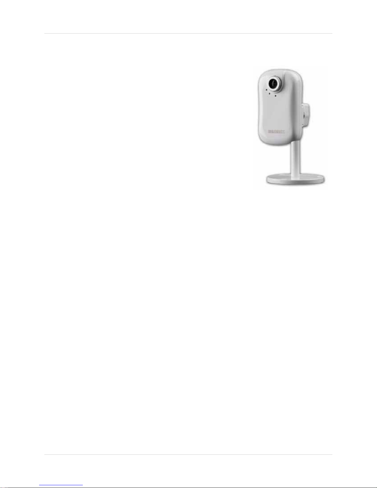
LNE1001 Features
• No networking knowledge required—GUARANTEED!
• Plug in Camera, Run Discovery CD (DigiConsole, included)
• CONNECT
• No DDNS/router configuration required
• Wired connectivity
®
• Remote Easy Connect (Yoics™ and MSN
• 10x digital zoom
• Supports VGA (640x480) resolution, 30 frames per second (real
time)
• Web browser support: Internet Explorer, Firefox, Safari for
viewing on PC or Mac
• Supports MPEG4, MJPEG, 3GPP
• MPEG4 enhanced compression for efficient video streaming
)
• Motion event triggers e-mail notification with JPEG image attachment 3GPP mobile support
(e.g. iPhone
• Two-way audio via integrated microphone and external speakers (not included)
• 6 channel surveillance application for real time viewing and recording
• Free LOREX DDNS included for remote connection
• Secure web management connectivity (password protected)
• Professional grade camera (HTTP event – camera can trigger or be triggered by other LOREX
camera)
• Windows Vista
®
compatible)
®
compatible
It really is that easy!
vii
Page 8
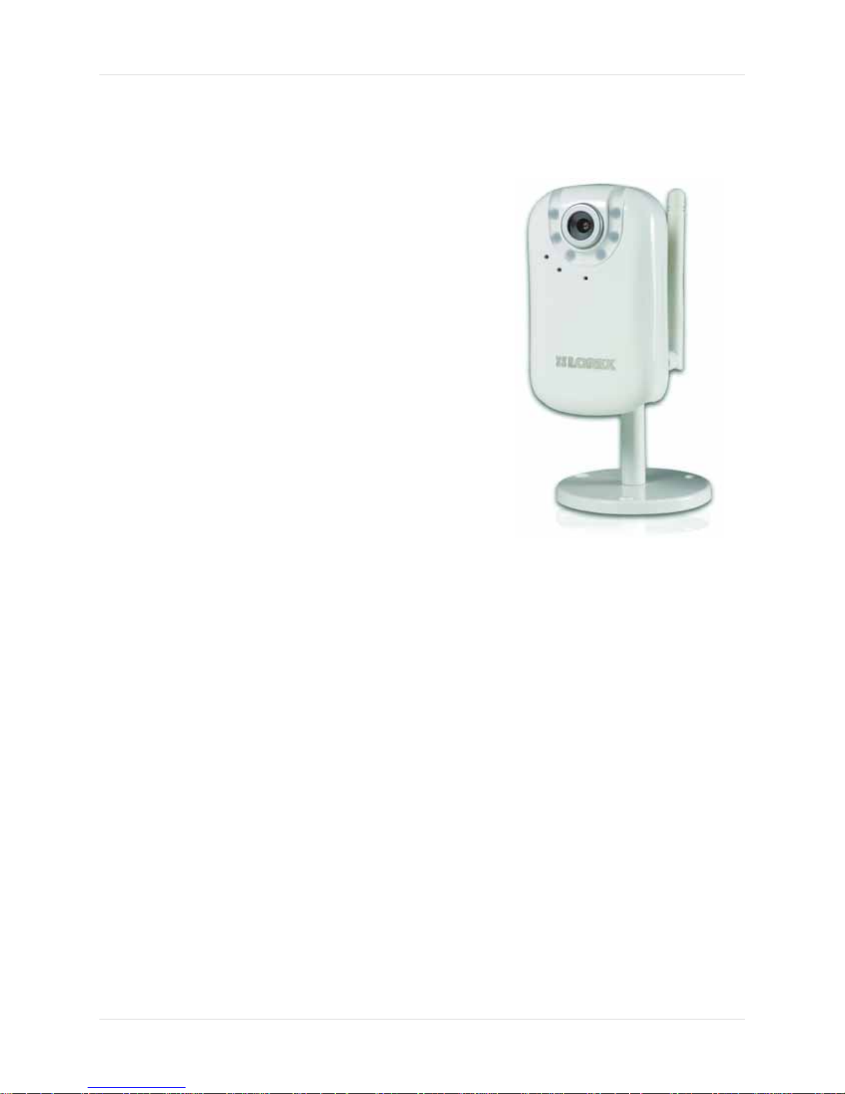
LNE3003 Features
• No Networking Knowledge Required,
GUARANTEED!
• Plug in Camera, Run Discovery CD
(DigiConsole, included)
• CONNECT
• No DDNS/Router Configuration Required
• Wired / Wireless IEEE 802.11b/g connectivity for
flexible installation
• Remote Easy Connect (Yoics and MSN)
• 10x Digital Zoom
• Superior low-light performance with
night-vision LEDs
• Supports VGA (640x480) resolution, 30 frames
per second (real time)
• Web browser support: Internet Explorer,
Firefox, Safari, for viewing on PC or Mac
• Supports MPEG4, MJPEG, 3GPP
• MPEG4 enhanced compression for efficient video streaming
• Motion event triggers e-mail notification with JPEG image attachment
• 3GPP mobile support (e.g. iPhone
• Two-way audio via integrated microphone and external speakers (not included)
• 6 channel surveillance application for real time viewing and recording
• Free LOREX DDNS included for guaranteed connection
• Secure web management User/Password protection
• Windows Vista Compatible
compatible)
It really is that easy!
viii
Page 9

LNE4001 Features
• Wired/wireless 802.11b/g connectivity for flexible
installation
• Professional grade camera (HTTP Event – camera
can trigger or be triggered by other LOREX camera)
• Pan tilt control via iPhone
• Preset pan tilt tour
• Night vision - 30ft (10m), IR LEDs
• Remote easy connect (Yoics and MSN)
• No DDNS/router configuration required
• Secure web management connectivity (password protected)
• No networking knowledge required, GUARANTEED!
• Plug in Camera, Run Discovery CD (DigiConsole, included)
• CONNECT
• 10 x digital zoom
• 6-channel surveillance application for viewing and archiving
• Two-way audio via audio input/output (external microphone/speakers needed)
• Enhanced MPEG4 compression for efficient video streaming
• Crystal clear video quality in VGA (640x480) resolution @ 30 frames per second
• Supports common browsers (Internet Explorer, Firefox, Safari) to be viewed using PC or Mac
• Mobile support (3GPP) iPhone and iPod Touch
• Alarm input/output (camera can be integrated with an alarm system—alarm triggers camera/
motion triggers alarm)
• Motion event triggers e-mail notification with JPEG attachment
• No DDNS/router configuration required
• Windows Vista compatible
®
It really is that easy!
Windows Vista is a registered trademark of Microsoft Corporation. iPhone and iPod touch are registered trademarks of Apple, Inc. Other
trademarks are the property of Lorex Technology Inc. We reserve the right to change models, configurations or specifications without
notice or liability. Product may not be exactly as shown.
ix
Page 10

x
Page 11

TABLE OF CONTENTS
Getting Started . . . . . . . . . . . . . . . . . . . . . . . . . . . . . . . . . . . . . . . . . . . . . . . . . 1
System Requirements . . . . . . . . . . . . . . . . . . . . . . . . . . . . . . . . . . . . . . . . . . . 2
Additional Requirements . . . . . . . . . . . . . . . . . . . . . . . . . . . . . . . . . . . . . . . . . . . . . . . . . . 2
About Yoics . . . . . . . . . . . . . . . . . . . . . . . . . . . . . . . . . . . . . . . . . . . . . . . . . . . . . . . . . . . . . 2
Camera Overview . . . . . . . . . . . . . . . . . . . . . . . . . . . . . . . . . . . . . . . . . . . . . . . 3
LNE1001 Wired, Easy-Connect Internet Camera . . . . . . . . . . . . . . . . . . . . . . . . . . . . . . 3
LNE3003 Wired/Wireless, Day/Night, East-Connect Internet Camera . . . . . . . . . . . . 4
LNZ4001 Wired/Wireless, Day/Night, Pan/Tilt, Easy-Connect Internet Camera . . . . 5
Rear Panel . . . . . . . . . . . . . . . . . . . . . . . . . . . . . . . . . . . . . . . . . . . . . . . . . . . . . 6
LNE1001 . . . . . . . . . . . . . . . . . . . . . . . . . . . . . . . . . . . . . . . . . . . . . . . . . . . . . . . . . . . . . . . 6
LNE3003 Series . . . . . . . . . . . . . . . . . . . . . . . . . . . . . . . . . . . . . . . . . . . . . . . . . . . . . . . . .6
LNZ4001 . . . . . . . . . . . . . . . . . . . . . . . . . . . . . . . . . . . . . . . . . . . . . . . . . . . . . . . . . . . . . . . 7
Setting Up the Camera . . . . . . . . . . . . . . . . . . . . . . . . . . . . . . . . . . . . . . . . . . . 8
Positioning The Camera. . . . . . . . . . . . . . . . . . . . . . . . . . . . . . . . . . . . . . . . . . 9
Installation Warnings . . . . . . . . . . . . . . . . . . . . . . . . . . . . . . . . . . . . . . . . . . . . . . . . . . . . . 9
Night Vision . . . . . . . . . . . . . . . . . . . . . . . . . . . . . . . . . . . . . . . . . . . . . . . . . . . . . . . . . . . . . 9
Mounting the Camera. . . . . . . . . . . . . . . . . . . . . . . . . . . . . . . . . . . . . . . . . . . 10
Connecting the Camera . . . . . . . . . . . . . . . . . . . . . . . . . . . . . . . . . . . . . . . . . 11
Configuring the Camera. . . . . . . . . . . . . . . . . . . . . . . . . . . . . . . . . . . . . . . . . 12
Opening DigiConsole . . . . . . . . . . . . . . . . . . . . . . . . . . . . . . . . . . . . . . . . . . . . . . . . . . . . 12
Finding Your Camera as an UPnP Device (optional) . . . . . . . . . . . . . . . . . . . . . . . . . . . 13
Viewing Your Camera Using a Mac . . . . . . . . . . . . . . . . . . . . . . . . . . . . . . . . . . . . . . . . . 14
Using The Camera. . . . . . . . . . . . . . . . . . . . . . . . . . . . . . . . . . . . . . . . . . . . . . 15
About DigiViewer . . . . . . . . . . . . . . . . . . . . . . . . . . . . . . . . . . . . . . . . . . . . . . . . . . . . . . . 15
Setting Up Local Viewing . . . . . . . . . . . . . . . . . . . . . . . . . . . . . . . . . . . . . . . . . . . . . . . . . 16
Adjusting Focus . . . . . . . . . . . . . . . . . . . . . . . . . . . . . . . . . . . . . . . . . . . . . . . . . . . . . . . .17
Controlling PTZ . . . . . . . . . . . . . . . . . . . . . . . . . . . . . . . . . . . . . . . . . . . . . . . . 18
LNZ4001 . . . . . . . . . . . . . . . . . . . . . . . . . . . . . . . . . . . . . . . . . . . . . . . . . . . . . . . . . . . . . . . . . . . . . . . . . . . . 18
Presets, Tours, and Patrols . . . . . . . . . . . . . . . . . . . . . . . . . . . . . . . . . . . . . . . . . . . . . . 20
A: Setting Presets . . . . . . . . . . . . . . . . . . . . . . . . . . . . . . . . . . . . . . . . . . . . . . . . . . . . . . . . . . . . . . . . . . . . . . . . . . . .20
B: Customizing Tours . . . . . . . . . . . . . . . . . . . . . . . . . . . . . . . . . . . . . . . . . . . . . . . . . . . . . . . . . . . . . . . . . . . . . . . . .21
C: Using Patrols . . . . . . . . . . . . . . . . . . . . . . . . . . . . . . . . . . . . . . . . . . . . . . . . . . . . . . . . . . . . . . . . . . . . . . . . . . . . .23
Using Yoics. . . . . . . . . . . . . . . . . . . . . . . . . . . . . . . . . . . . . . . . . . . . . . . . . . . . 24
Registering with Yoics . . . . . . . . . . . . . . . . . . . . . . . . . . . . . . . . . . . . . . . . . . . . . . . . . . . 24
Registering Your Camera . . . . . . . . . . . . . . . . . . . . . . . . . . . . . . . . . . . . . . . . . . . . . . . . 25
Remote Viewing Using a Web Browser . . . . . . . . . . . . . . . . . . . . . . . . . . . . . . . . . . . . . 27
xi
Page 12

Setting Up Wireless Connectivity . . . . . . . . . . . . . . . . . . . . . . . . . . . . . . . . . . . . . . . . . . 28
Remote Viewing from iPhone and iPod touch . . . . . . . . . . . . . . . . . . . . . . . . . . . . . . . . 29
Remote Viewing Using MSN Messenger . . . . . . . . . . . . . . . . . . . . . . . . . . . 30
Creating an MSN Account . . . . . . . . . . . . . . . . . . . . . . . . . . . . . . . . . . . . . . . . . . . . . . . . 30
Download and Install Messenger . . . . . . . . . . . . . . . . . . . . . . . . . . . . . . . . . . . . . . . . . . . . . . . . . . . . . . . 30
Configuring MSN Messenger on Your Camera . . . . . . . . . . . . . . . . . . . . . . . . . . . . . . . 31
Configuring MSN Messenger . . . . . . . . . . . . . . . . . . . . . . . . . . . . . . . . . . . . . . . . . . . . .31
Can’t See the Video? . . . . . . . . . . . . . . . . . . . . . . . . . . . . . . . . . . . . . . . . . . . . . . . . . . . . . . . . . . . . . . . . . . 32
DigiConsole . . . . . . . . . . . . . . . . . . . . . . . . . . . . . . . . . . . . . . . . . . . 33
About DigiConsole . . . . . . . . . . . . . . . . . . . . . . . . . . . . . . . . . . . . . . . . . . . . . . . . . . . . . . 33
System Requirements . . . . . . . . . . . . . . . . . . . . . . . . . . . . . . . . . . . . . . . . . . . . . . . . . . . 33
Using DigiConsole. . . . . . . . . . . . . . . . . . . . . . . . . . . . . . . . . . . . . . . . . . . . . . 34
Home . . . . . . . . . . . . . . . . . . . . . . . . . . . . . . . . . . . . . . . . . . . . . . . . . . . . . . . . . . . . . . . . . 34
Find . . . . . . . . . . . . . . . . . . . . . . . . . . . . . . . . . . . . . . . . . . . . . . . . . . . . . . . . . . . . . . . . . .35
Find Menu Options . . . . . . . . . . . . . . . . . . . . . . . . . . . . . . . . . . . . . . . . . . . . . . . . . . . . . . . . . . . . . . . . . . . 35
Open device in browser . . . . . . . . . . . . . . . . . . . . . . . . . . . . . . . . . . . . . . . . . . . . . . . . . . . . . . . . . . . . . . . . . . . . . . . 35
View Live Image . . . . . . . . . . . . . . . . . . . . . . . . . . . . . . . . . . . . . . . . . . . . . . . . . . . . . . . . . . . . . . . . . . . . . . . . . . . . .36
Refresh list of devices . . . . . . . . . . . . . . . . . . . . . . . . . . . . . . . . . . . . . . . . . . . . . . . . . . . . . . . . . . . . . . . . . . . . . . . . 36
Live Video Options . . . . . . . . . . . . . . . . . . . . . . . . . . . . . . . . . . . . . . . . . . . . . . . . . . . . . . . . . . . . . . . . . . . . 37
Open device in browser . . . . . . . . . . . . . . . . . . . . . . . . . . . . . . . . . . . . . . . . . . . . . . . . . . . . . . . . . . . . . . . . . . . . . . . 37
Stop Live Video . . . . . . . . . . . . . . . . . . . . . . . . . . . . . . . . . . . . . . . . . . . . . . . . . . . . . . . . . . . . . . . . . . . . . . . . . . . . . . 37
Record Video Image . . . . . . . . . . . . . . . . . . . . . . . . . . . . . . . . . . . . . . . . . . . . . . . . . . . . . . . . . . . . . . . . . . . . . . . . . .37
Mute Audio From Camera . . . . . . . . . . . . . . . . . . . . . . . . . . . . . . . . . . . . . . . . . . . . . . . . . . . . . . . . . . . . . . . . . . . . . 37
Enable microphone . . . . . . . . . . . . . . . . . . . . . . . . . . . . . . . . . . . . . . . . . . . . . . . . . . . . . . . . . . . . . . . . . . . . . . . . . . . 38
Full-screen Mode . . . . . . . . . . . . . . . . . . . . . . . . . . . . . . . . . . . . . . . . . . . . . . . . . . . . . . . . . . . . . . . . . . . . . . . . . . . . 38
Refresh the list of devices . . . . . . . . . . . . . . . . . . . . . . . . . . . . . . . . . . . . . . . . . . . . . . . . . . . . . . . . . . . . . . . . . . . . .38
Register . . . . . . . . . . . . . . . . . . . . . . . . . . . . . . . . . . . . . . . . . . . . . . . . . . . . . . . . . . . . . . . . . . . . . . . . . . . . 38
Installing DigiConsole . . . . . . . . . . . . . . . . . . . . . . . . . . . . . . . . . . . . . . . . . . 39
Uninstalling DigiConsole . . . . . . . . . . . . . . . . . . . . . . . . . . . . . . . . . . . . . . . . 40
Recording Live Video . . . . . . . . . . . . . . . . . . . . . . . . . . . . . . . . . . . . . . . . . . . 41
Playing Recorded Video . . . . . . . . . . . . . . . . . . . . . . . . . . . . . . . . . . . . . . . . . 42
DigiViewer . . . . . . . . . . . . . . . . . . . . . . . . . . . . . . . . . . . . . . . . . . . . 43
About DigiViewer . . . . . . . . . . . . . . . . . . . . . . . . . . . . . . . . . . . . . . . . . . . . . . . . . . . . . . . 43
Opening DigiViewer . . . . . . . . . . . . . . . . . . . . . . . . . . . . . . . . . . . . . . . . . . . . 44
DigiConsole . . . . . . . . . . . . . . . . . . . . . . . . . . . . . . . . . . . . . . . . . . . . . . . . . . . . . . . . . . . . . . . . . . . . . . . . . . . . . . . . .44
Web browser . . . . . . . . . . . . . . . . . . . . . . . . . . . . . . . . . . . . . . . . . . . . . . . . . . . . . . . . . . . . . . . . . . . . . . . . . . . . . . . . 44
Surveillance . . . . . . . . . . . . . . . . . . . . . . . . . . . . . . . . . . . . . . . . . . . . . . . . . . 45
User . . . . . . . . . . . . . . . . . . . . . . . . . . . . . . . . . . . . . . . . . . . . . . . . . . . . . . . . . . . . . . . . . . 45
Main Display Screen . . . . . . . . . . . . . . . . . . . . . . . . . . . . . . . . . . . . . . . . . . . . . . . . . . . . . 45
Main Menu . . . . . . . . . . . . . . . . . . . . . . . . . . . . . . . . . . . . . . . . . . . . . . . . . . . . . . . . . . . . . 46
Advanced Controls Tool Panel . . . . . . . . . . . . . . . . . . . . . . . . . . . . . . . . . . . . . . . . . . . . 46
Audio . . . . . . . . . . . . . . . . . . . . . . . . . . . . . . . . . . . . . . . . . . . . . . . . . . . . . . . . . . . . . . . . . 46
Still Image Capture Button . . . . . . . . . . . . . . . . . . . . . . . . . . . . . . . . . . . . . . . . . . . . . . . 46
Advanced Controls Toolbar . . . . . . . . . . . . . . . . . . . . . . . . . . . . . . . . . . . . . . . . . . . . . . . 47
xii
Page 13

Channel Display . . . . . . . . . . . . . . . . . . . . . . . . . . . . . . . . . . . . . . . . . . . . . . . . . . . . . . . . . . . . . . . . . . . . . 47
PTZ . . . . . . . . . . . . . . . . . . . . . . . . . . . . . . . . . . . . . . . . . . . . . . . . . . . . . . . . . . . . . . . . . . . . . . . . . . . . . . . . 47
Picture . . . . . . . . . . . . . . . . . . . . . . . . . . . . . . . . . . . . . . . . . . . . . . . . . . . . . . . . . . . . . . . . . . . . . . . . . . . . . 47
Rotate Image . . . . . . . . . . . . . . . . . . . . . . . . . . . . . . . . . . . . . . . . . . . . . . . . . . . . . . . . . . . . . . . . . . . . . . . . 47
Live Image . . . . . . . . . . . . . . . . . . . . . . . . . . . . . . . . . . . . . . . . . . . . . . . . . . . . . . . . . . . . . 47
Events. . . . . . . . . . . . . . . . . . . . . . . . . . . . . . . . . . . . . . . . . . . . . . . . . . . . . . . . 48
Motion Events . . . . . . . . . . . . . . . . . . . . . . . . . . . . . . . . . . . . . . . . . . . . . . . . . . . . . . . . . .48
HTTP Events . . . . . . . . . . . . . . . . . . . . . . . . . . . . . . . . . . . . . . . . . . . . . . . . . . . . . . . . . . . 49
Discovery . . . . . . . . . . . . . . . . . . . . . . . . . . . . . . . . . . . . . . . . . . . . . . . . . . . . . . . . . . . . . . 50
UPnP . . . . . . . . . . . . . . . . . . . . . . . . . . . . . . . . . . . . . . . . . . . . . . . . . . . . . . . . . . . . . . . . . . . . . . . . . . . . . . 50
Preset . . . . . . . . . . . . . . . . . . . . . . . . . . . . . . . . . . . . . . . . . . . . . . . . . . . . . . . . . . . . . . . .51
Home Position . . . . . . . . . . . . . . . . . . . . . . . . . . . . . . . . . . . . . . . . . . . . . . . . . . . . . . . . . . . . . . . . . . . . . . . 52
Patrol Control . . . . . . . . . . . . . . . . . . . . . . . . . . . . . . . . . . . . . . . . . . . . . . . . . . . . . . . . . . 53
Alarm Input/Output . . . . . . . . . . . . . . . . . . . . . . . . . . . . . . . . . . . . . . . . . . . . . . . . . . . . . 54
Alarm Input . . . . . . . . . . . . . . . . . . . . . . . . . . . . . . . . . . . . . . . . . . . . . . . . . . . . . . . . . . . . . . . . . . . . . . . . . 54
Alarm Output . . . . . . . . . . . . . . . . . . . . . . . . . . . . . . . . . . . . . . . . . . . . . . . . . . . . . . . . . . . . . . . . . . . . . . . . 55
Settings . . . . . . . . . . . . . . . . . . . . . . . . . . . . . . . . . . . . . . . . . . . . . . . . . . . . . . 56
Preferences . . . . . . . . . . . . . . . . . . . . . . . . . . . . . . . . . . . . . . . . . . . . . . . . . . . . . . . . . . . 57
Device Description . . . . . . . . . . . . . . . . . . . . . . . . . . . . . . . . . . . . . . . . . . . . . . . . . . . . . . . . . . . . . . . . . . . 57
On Screen Display . . . . . . . . . . . . . . . . . . . . . . . . . . . . . . . . . . . . . . . . . . . . . . . . . . . . . . . . . . . . . . . . . . . . 57
Lighting . . . . . . . . . . . . . . . . . . . . . . . . . . . . . . . . . . . . . . . . . . . . . . . . . . . . . . . . . . . . . . . . . . . . . . . . . . . . 58
Device Setup . . . . . . . . . . . . . . . . . . . . . . . . . . . . . . . . . . . . . . . . . . . . . . . . . . . . . . . . . . . 58
Local Network Settings . . . . . . . . . . . . . . . . . . . . . . . . . . . . . . . . . . . . . . . . . . . . . . . . . . . . . . . . . . . . . . . 58
System Clock . . . . . . . . . . . . . . . . . . . . . . . . . . . . . . . . . . . . . . . . . . . . . . . . . . . . . . . . . . . . . . . . . . . . . . . . 59
OPTIONAL: . . . . . . . . . . . . . . . . . . . . . . . . . . . . . . . . . . . . . . . . . . . . . . . . . . . . . . . . . . . . . . . . . . . . . . . . . . . . . . . . . . 59
Network Configuration . . . . . . . . . . . . . . . . . . . . . . . . . . . . . . . . . . . . . . . . . . . . . . . . . . . . . . . . . . . . . . . . 60
Remote Access . . . . . . . . . . . . . . . . . . . . . . . . . . . . . . . . . . . . . . . . . . . . . . . . . . . . . . . . .61
Yoics Instant Networking . . . . . . . . . . . . . . . . . . . . . . . . . . . . . . . . . . . . . . . . . . . . . . . . . . . . . . . . . . . . . . 61
MSN Messenger . . . . . . . . . . . . . . . . . . . . . . . . . . . . . . . . . . . . . . . . . . . . . . . . . . . . . . . . . . . . . . . . . . . . . 62
Dynamic DNS . . . . . . . . . . . . . . . . . . . . . . . . . . . . . . . . . . . . . . . . . . . . . . . . . . . . . . . . . . . . . . . . . . . . . . . . 62
Network Services . . . . . . . . . . . . . . . . . . . . . . . . . . . . . . . . . . . . . . . . . . . . . . . . . . . . . . . 63
Outgoing Email Server . . . . . . . . . . . . . . . . . . . . . . . . . . . . . . . . . . . . . . . . . . . . . . . . . . . . . . . . . . . . . . . . 63
Network Recorder Server . . . . . . . . . . . . . . . . . . . . . . . . . . . . . . . . . . . . . . . . . . . . . . . . . . . . . . . . . . . . . 64
Accounts . . . . . . . . . . . . . . . . . . . . . . . . . . . . . . . . . . . . . . . . . . . . . . . . . . . . . . . . . . . . . . 65
Current User Account . . . . . . . . . . . . . . . . . . . . . . . . . . . . . . . . . . . . . . . . . . . . . . . . . . . . . . . . . . . . . . . . . 65
General User Accounts . . . . . . . . . . . . . . . . . . . . . . . . . . . . . . . . . . . . . . . . . . . . . . . . . . . . . . . . . . . . . . . . 66
Anonymous Guest Account . . . . . . . . . . . . . . . . . . . . . . . . . . . . . . . . . . . . . . . . . . . . . . . . . . . . . . . . . . . . 66
Wireless . . . . . . . . . . . . . . . . . . . . . . . . . . . . . . . . . . . . . . . . . . . . . . . . . . . . . . . . . . . . . . 67
Wireless Settings . . . . . . . . . . . . . . . . . . . . . . . . . . . . . . . . . . . . . . . . . . . . . . . . . . . . . . . . . . . . . . . . . . . . 67
Channels . . . . . . . . . . . . . . . . . . . . . . . . . . . . . . . . . . . . . . . . . . . . . . . . . . . . . . . . . . . . . . 68
Remote Cameras and Video Servers . . . . . . . . . . . . . . . . . . . . . . . . . . . . . . . . . . . . . . . . . . . . . . . . . . . . . 68
System . . . . . . . . . . . . . . . . . . . . . . . . . . . . . . . . . . . . . . . . . . . . . . . . . . . . . . . . . . . . . . . . 69
Advanced Parameter Settings . . . . . . . . . . . . . . . . . . . . . . . . . . . . . . . . . . . . . . . . . . . . . . . . . . . . . . . . . . 69
Upgrading Firmware . . . . . . . . . . . . . . . . . . . . . . . . . . . . . . . . . . . . . . . . . . . . . . . . . . . . . . . . . . . . . . . . . . 69
System Log . . . . . . . . . . . . . . . . . . . . . . . . . . . . . . . . . . . . . . . . . . . . . . . . . . . 70
Help . . . . . . . . . . . . . . . . . . . . . . . . . . . . . . . . . . . . . . . . . . . . . . . . . . . . . . . . . 71
xiii
Page 14

Appendix A: Camera Specifications . . . . . . . . . . . . . . . . . . . . . . . . . . . . . . . 73
LNE1001 . . . . . . . . . . . . . . . . . . . . . . . . . . . . . . . . . . . . . . . . . . . . . . . . . . . . . . . . . . . . . .73
LNE3003 . . . . . . . . . . . . . . . . . . . . . . . . . . . . . . . . . . . . . . . . . . . . . . . . . . . . . . . . . . . . . .74
LNZ4001 . . . . . . . . . . . . . . . . . . . . . . . . . . . . . . . . . . . . . . . . . . . . . . . . . . . . . . . . . . . . . . 75
Appendix B: Adding Cameras . . . . . . . . . . . . . . . . . . . . . . . . . . . . . . . . . . . . 76
Setting up Additional Cameras . . . . . . . . . . . . . . . . . . . . . . . . . . . . . . . . . . . . . . . . . . . . 76
Finding the Additional Cameras . . . . . . . . . . . . . . . . . . . . . . . . . . . . . . . . . . . . . . . . . . .76
Port Ranges . . . . . . . . . . . . . . . . . . . . . . . . . . . . . . . . . . . . . . . . . . . . . . . . . . . . . . . . . . . . . . . . . . . . . . . . . 77
Adding Cameras to DigiViewer . . . . . . . . . . . . . . . . . . . . . . . . . . . . . . . . . . . . . . . . . . . . 78
Viewing Cameras . . . . . . . . . . . . . . . . . . . . . . . . . . . . . . . . . . . . . . . . . . . . . . . . . . . . . . . 79
Appendix C: Network Connectivity . . . . . . . . . . . . . . . . . . . . . . . . . . . . . . . . 80
Locating the IP and MAC addresses . . . . . . . . . . . . . . . . . . . . . . . . . . . . . . . . . . . . . . . . 81
Appendix D: Router Port Forwarding. . . . . . . . . . . . . . . . . . . . . . . . . . . . . . 82
Appendix E: Setting Up DDNS Service . . . . . . . . . . . . . . . . . . . . . . . . . . . . . 83
Configuring DDNS in DigiViewer . . . . . . . . . . . . . . . . . . . . . . . . . . . . . . . . . . . . . . . . . . . 85
Appendix F: Connecting Alarm and Motion Devices. . . . . . . . . . . . . . . . . . 86
Appendix G: Remote Access with Internet Explorer . . . . . . . . . . . . . . . . . 87
Internet Explorer Security Warnings . . . . . . . . . . . . . . . . . . . . . . . . . . . . . . . . . . . . . . . 88
Appendix H: Setting Up HTTP Events . . . . . . . . . . . . . . . . . . . . . . . . . . . . . . 89
Example . . . . . . . . . . . . . . . . . . . . . . . . . . . . . . . . . . . . . . . . . . . . . . . . . . . . . . . . . . . . . . . 89
Positioning the Cameras . . . . . . . . . . . . . . . . . . . . . . . . . . . . . . . . . . . . . . . . . . . . . . . . . . . . . . . . . . . . . . 89
Setting a Preset . . . . . . . . . . . . . . . . . . . . . . . . . . . . . . . . . . . . . . . . . . . . . . . . . . . . . . . . . . . . . . . . . . . . . . . . . . . . .89
Entering HTTP Event Information . . . . . . . . . . . . . . . . . . . . . . . . . . . . . . . . . . . . . . . . . . . . . . . . . . . . . . . . . . . . . . . 90
Result . . . . . . . . . . . . . . . . . . . . . . . . . . . . . . . . . . . . . . . . . . . . . . . . . . . . . . . . . . . . . . . . . . . . . . . . . . . . . . 91
Appendix I: Rebooting, Resetting, and Recalibrating the Camera . . . . . . 92
Rebooting the Camera . . . . . . . . . . . . . . . . . . . . . . . . . . . . . . . . . . . . . . . . . . . . . . . . . . . 92
Restoring Factory Defaults . . . . . . . . . . . . . . . . . . . . . . . . . . . . . . . . . . . . . . . . . . . . . . .92
Resetting the Camera . . . . . . . . . . . . . . . . . . . . . . . . . . . . . . . . . . . . . . . . . . . . . . . . . . . 93
Recalibrating the Camera . . . . . . . . . . . . . . . . . . . . . . . . . . . . . . . . . . . . . . . . . . . . . . . . 93
Appendix J: Registering, Removing, and Resetting Yoics Services . . . . . 94
Registering Your Camera . . . . . . . . . . . . . . . . . . . . . . . . . . . . . . . . . . . . . . . . . . . . . . . . 94
Removing Yoics Services . . . . . . . . . . . . . . . . . . . . . . . . . . . . . . . . . . . . . . . . . . . . . . . . . 97
Removing Services Using DigiViewer . . . . . . . . . . . . . . . . . . . . . . . . . . . . . . . . . . . . . . . . . . . . . . . . . . . . 98
Resetting Yoics Services . . . . . . . . . . . . . . . . . . . . . . . . . . . . . . . . . . . . . . . . . . . . . . . . . 98
Troubleshooting Camera Registration . . . . . . . . . . . . . . . . . . . . . . . . . . . . . . . . . . . . . 99
xiv
Page 15
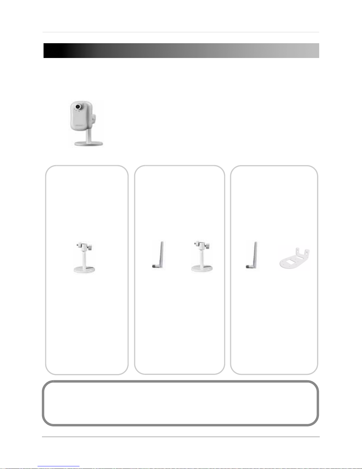
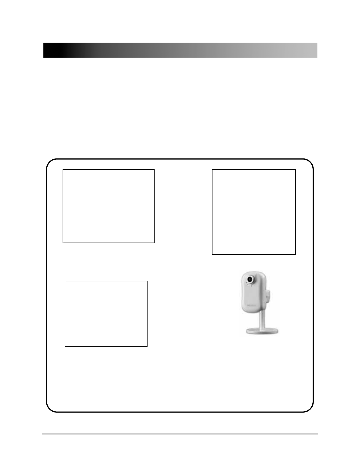
GETTING STARTED
LNE1001 LNE3003 LNZ4001
POWER SUPPLY
QUICKSTART GUIDE
DOCUMENTATION CD
MOUNTING KIT
MOUNTING STAND
ETHERNET CABLE
MOUNTING KIT
WIRELESS
ANTENNA
MOUNTING
STAND
WIRELESS
ANTENNA
MOUNTING
BRACKET
MOUNTING KIT
POWER SUPPLY
POWER SUPPLY
ETHERNET CABLE
QUICKSTART GUIDE
DOCUMENTATION CD
QUICKSTART GUIDE
DOCUMENTATION CD
The system comes with the following components:
ETHERNET CABLE
*CAMERA CONFIGURATION MAY VARY BY MODEL. PLEASE REFER TO YOUR PACKAGE FOR
SPECIFIC DETAILS.
CHECK YOUR PACKAGE TO CONFIRM THAT YOU HAVE RECEIVED THE COMPLETE SYSTEM,
INCLUDING ALL COMPONENTS SHOWN ABOVE.
1
Page 16

SYSTEM REQUIREMENTS
For setup and viewing, the camera requires the following:
• PC running Windows Vista / XP
• Internet
• Web browser: Internet Explorer 7 or later (with Active X), Mozilla Firefox, Safari
NOTE: If you are using a Mac, only certain functions are available on the camera. For details, see “Viewing
Your Camera Using a Mac” on page 14.
Additional Requirements
To view your camera from a remote computer (remote viewing using Yoics), you may need to
install the following:
• QuickTime
camera using Yoics. Download QuickTime at www
• QuickTime is also required for use with Web browser
Safari
About Yoics
Yoics is secure, instant networking made easy. This camera is designed to work with Yoics
easy-connect remote access, letting you connect to
www.yoics.com for
NOTE: This manual refe rs to the camera opera ti ng using the Yoics Easy Connect Remote Access service.
Yoics Easy Connect Remote Access service is subject to improvements and changes made by Yoics.
connection
®
7 or later: The QuickTime plug-in is required to view streaming video from your
.apple.com/quicktime/download
s other than Internet Explorer, i.e. Firefox,
your camera anywhere, anytime. Visit
more information on using Yoics.
2
Page 17
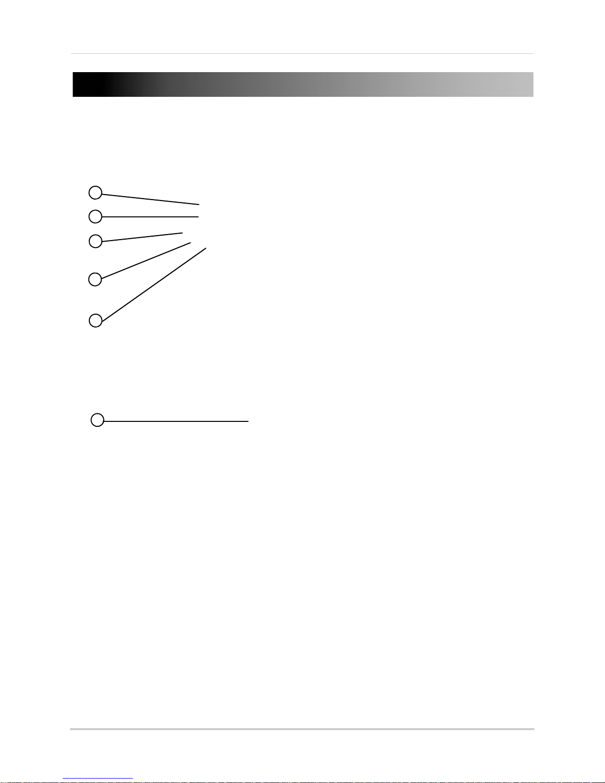
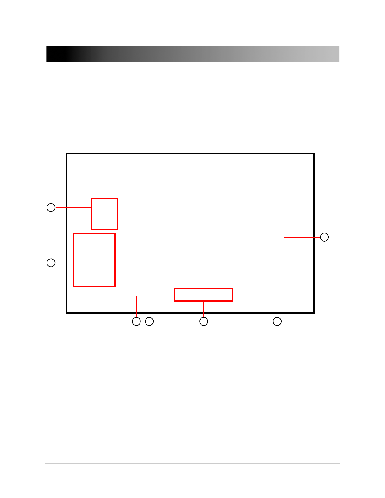
CAMERA OVERVIEW
1
2
3
4
5
6
LNE1001 Wired, Easy-Connect Internet Camera
1. Focus: Manually adjust the focus ring to sharpen the image.
2. Lens: 1/4"
3. Power LED
4. Network Indicator: Pluses blue du
5. Mi
6. Stand:
crophone: Built-in microphone for listen-in audio over the network.
lens with a CMOS image sensor.
Indicator: Lights up solid blue when camera is powered on.
Assembled support stand for the camera.
ring network access.
3
Page 18
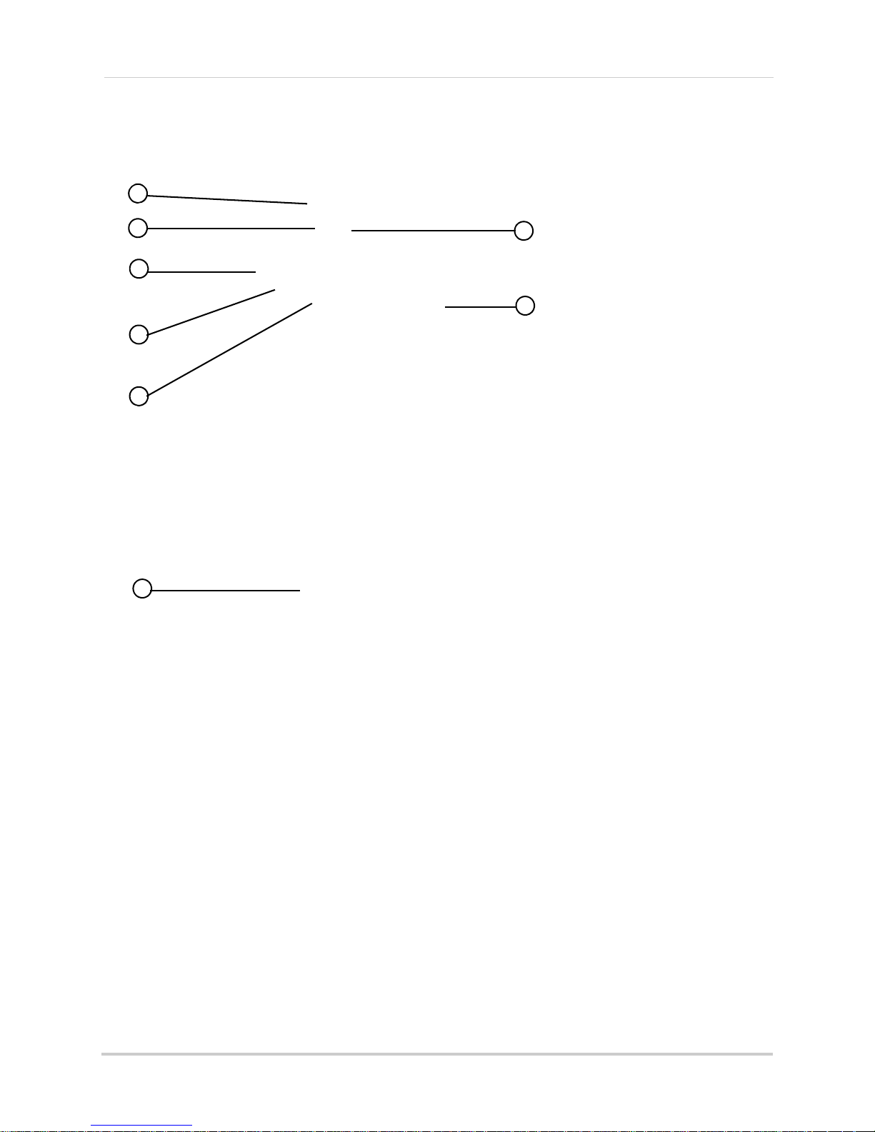
Camera Overview
1
2
3
4
5
6
8
7
LNE3003 Wired/Wireless, Day/Night, East-Connect
Internet Camera
1. Focus: Manually adjust the focus ring to sharpen the image.
2. Lens: 1/4"
3. Power LED
4. Network Indicator: Pluses blue du
5. Mi
6. Stand:
7. Infrared LEDs: 6 whit
8. Wireless Antenn
4
crophone: Built-in microphone for listen-in audio over the network.
lens with a CMOS image sensor.
Indicator: Lights up solid blue when camera is powered on.
ring network access.
Assembled support stand for the camera.
e-light LEDs for night vision.
a: Removable wireless antenna.
Page 19

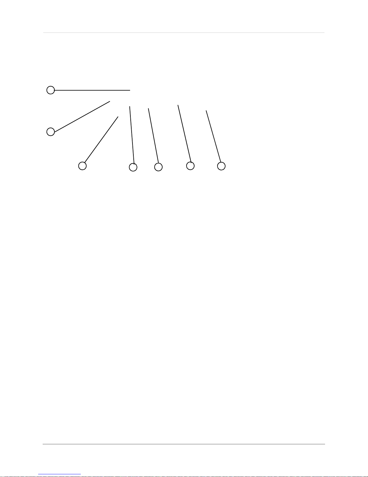
LNZ4001 Wired/Wireless, Day/Night, Pan/Tilt,
1
2
3
4
5
6
7
Easy-Connect Internet Camera
Camera Overview
1. Network Indicator: Pluses blue during network access.
2. Power LED
3. Mi
4. Infrared LEDs: 12
5. Focus: Man
6. Lens: 1/4"
7. Wireless Antenn
crophone: Built-in microphone for listen-in audio over the network.
Indicator: Lights up solid blue when camera is powered on.
IR LEDs for night vision.
ually adjust the focus ring to sharpen the image.
lens with a CMOS image sensor.
a: Removable wireless antenna.
5
Page 20

REAR PANEL
1
2
3
4
1
2
3 4
5
LNE1001
1. Speaker: 3.5 mm audio port for external speakers or other audio devices (not included).
2. Reset:
configuration.
3. LAN:
connect the other end of the network cable to a network router, switch, or active wall port.
4. DC
Using a paper-clip, hold for 10 seconds to reset the camera to its default
Network port. Connect one end of the included network cable to this port, and then
5V: Connect the 5V DC power adapter.
LNE3003 Series
1. DC 5V: Connect the 5V DC power adapter.
2. Reset:
configuration.
3. Speaker: 3.5 mm
4. LAN:
connect the other end of the network cable to a network router, switch, or active wall port.
5. Antenna Connection (SMA): Connect
Using a paper-clip, hold for 10 seconds to reset the camera to its default
audio port for external speakers or other audio devices (not included).
Network port. Connect one end of the included network cable to this port, and then
the wireless antenna—angle at 90°, 180°; rotate 360°.
6
Page 21
Rear Panel
1
2
3
4
5
6
7
LNZ4001
1. Antenna Connection (SMA): Connect the wireless antenna—angle at 90°, 180°; rotate 360°.
2. 12
3. Reset:
4. Audio I
5. Audio O
6. Ethernet: Ne
7. Alarm Bloc
VDC: Connect the 12V DC power adapter.
Using a paper-clip, hold for 10 seconds to reset the camera to its default
configuration.
n: 3.5 mm audio port for an external microphone (not included).
ut: 3.5 mm audio port for external speakers or other audio devices (not included).
twork port. Connect one end of the included network cable to this port, and then
connect the other end of the network cable to a network router, switch, or active wall port.
k: Connection block for external alarm/motion devices (not included).
7
Page 22
SETTING UP THE CAMERA
Figure 1.0 Assemble the pedestal
Figure 1.1 Attach pedestal to the camera
Figure 1.2 Attach the antenna to the
camera (LNE3003
/
LNZ4001
only
)
Figure 1.3 Fully assembled camera (from top-right, LNE1001,
LNZ4001, LNE3003)
Basic setup for your network camera.
NOTE: Pedestal assembly refers to LNE1001 and LNE3003 series
To set up the camera:
1. Attach the stand to the base
2. Attach the mounting bracket to the stand.
3. Attach the camera to the completed pedestal. Use the thumb screws to secure the camera
fi
rmly.
4. Attach the wireless antenna to the back of
the camera (LNE3003/LNZ4001 series
only
.
only
).
8
Page 23

POSITIONING THE CAMERA
Before you install the camera, carefully plan where and how it will be positioned.
Installation Warnings
• Select a location for the camera that provides a clear view of the area you want to monitor,
which is free from dust, and is not in line-of-sight to a strong light source or direct sunlight.
• Route the cables so that they are not close to power or telephone lines, transformers,
microwave ovens or other electrical equipment
• Select a location for the camera that has an ambient temperature between 32°F~113°F
(0°C~45°C); Humidity 20-80% relative humidity (non-condensing)
• If you plan to install the camera in a location that has conditions not recommended in this
manual, consult with a professional installer and consider use of a separate camera cover or
housing
• Before starting permanent installation, have another person hold the camera for you while
you verify its performance by observing the image on a monitor
Night Vision
The LNE3003 and LNZ4001 cameras include night
vision LEDs, which provide the camera with the ability
to view images in low light conditions. It is important to
use the provided power adaptor when using the camera
for prolonged
periods in low light conditions.
9
Page 24
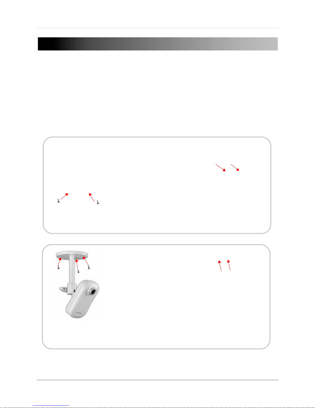
MOUNTING THE CAMERA
Wall Mounting
Figure 2.0 Secure camera to bracket
(LNZ4001 Series only)
Figure 2.1 Secure camera and bracket to wall
(LNZ4001 Series)
Figure 2.2 Ceiling mounting
(LNE1001/LNE3003 Series)
Figure 2.3 Secure camera and bracket to ceiling
(LNZ4001 Series)
Ceiling Mounting
The camera can be mounted to walls, ceilings, desks, tables, or other flat surfaces.
To mount the camera to a wall or ceiling:
1. Select a location for the camera. Make sure you are able to drive screws into the surface. If
nec
essary, use the mounting bracket/pedestal to mark holes for drilling.
2. Use the small screws included in the mounting kit to secure the camera to the mounting
only
br
acket (LNZ4001
3. Use the large screws and anchors to secure the camera and bracket/pedestal to the
mounting su
rface (see figure 2.1).
; see figure 2.0).
10
Page 25
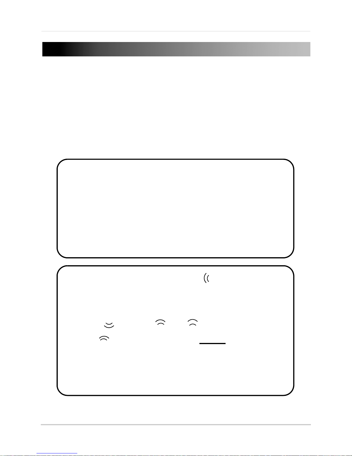
CONNECTING THE CAMERA
Figure 3.0 Wired connection (wired connection only needed for initial setup of wireless cameras)
Figure 3.1 Wireless connection
LNZ4001
LNE1001
LNE3003
LNZ4001
LAPTOP
PC
PC
With the camera assembled, you can now connect the power and network cables.
To connect the camera:
1. Connect the included Ethernet cable to the Ether
2. Connect the other end of the Ethernet cable to a network r
net port on the rear panel of the camera.
outer, switch, or active wall port.
NOTE: For a wireless connection, the camera only needs to be wired to your network for initial setup and
configuration. Once the camera is fully setup, you can disconnect the Ethernet cable and connect to your
network wirelessly.
3. Connect the power adapter to the camera.
4. Plug in the power adapter to a power outlet.
11
Page 26
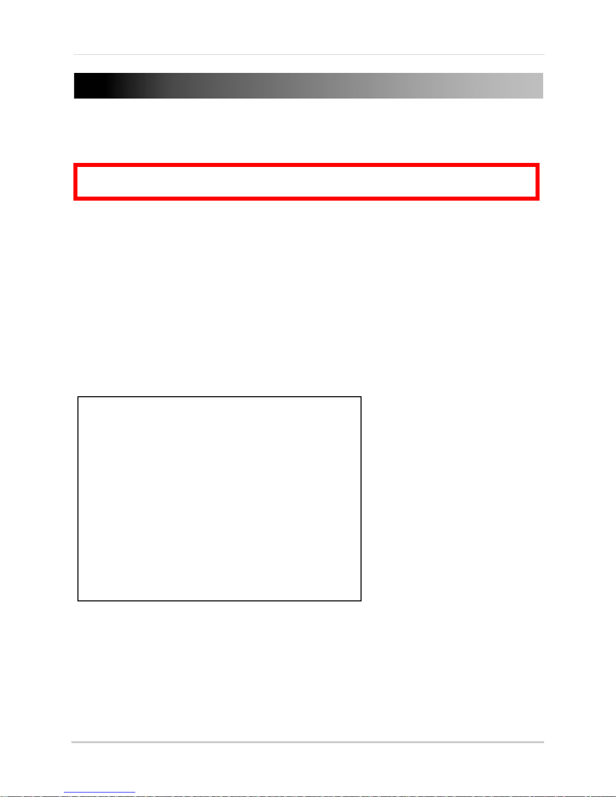
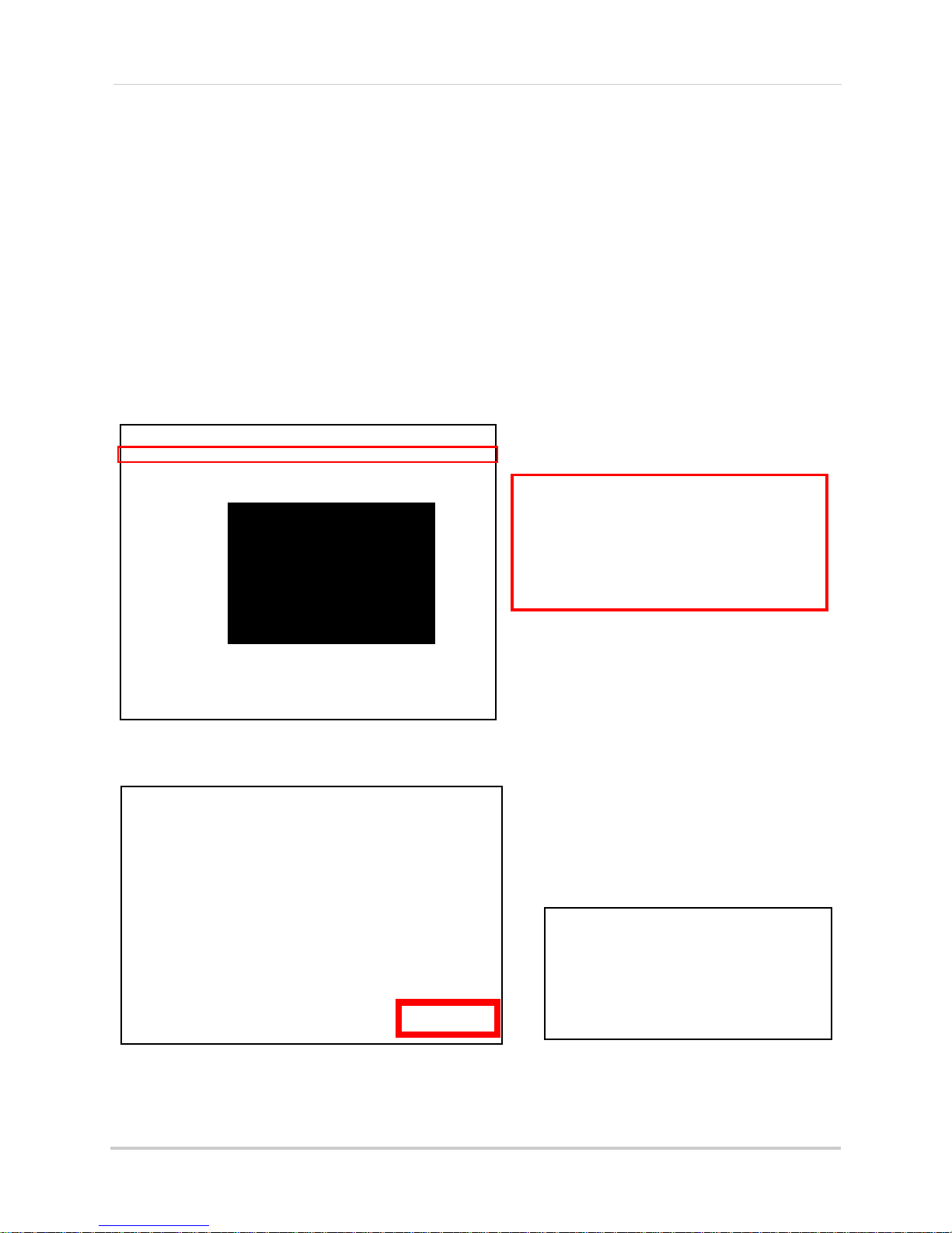
CONFIGURING THE CAMERA
ATTENTION: Before starting the installation, please ensure your computer is connected to the
same local network as the camera and has access to the Internet.
Figure 4.0 DigiConsole main window
With the camera setup and connected, you can now set up local viewing, remote viewing, and
wireless connectivity.
NOTE: It is recommended to install the camera when your computer is wired to the local network. If you
are using the wireless connection on your computer, please connect your computer to your wireless
router using an Ethernet cable (not included).
NOTE: The
Opening DigiConsole
Use DigiConsole to setup your camera.
NOTE: Prior to using DigiConsole, visit www.lorexcctv.com and check for software and firmware updates.
Please refer to the DigiConsole & DigiViewer Software Manual for more information on upgrading
firmware.
To open DigiConsole:
following refers to an installation on Windows Vista. Some steps may differ in Windows XP.
1. Insert the included DigiConsole software CD int
o your CD/DVD-ROM drive. DigiConsole
automatically launches.
2. If a security pop-up window appears, click Unblock and Con
tinue to allow DigiConsole access
to the Internet.
NOTE: If Autorun fails to start, go to Computer (My Computer for Windows XP users) and double-click
the CD-drive to run the application. Follow step 2.
NOTE: Y
record and playback video, you must install DigiConsole to your computer. Please refer to the DigiConsole
& DigiViewer Software Manual for more information on installing DigiConsole.
ou do not need to install DigiConsole to view live video from the camera. However, if you wish to
12
Page 27
3. Click Find to discover Lorex cameras on your network.
Figure 4.1 Select your camera from the list of devices
Figure 4.2 Turn on Network discovery
Figure 4.3 Allow Network discovery
Figure 4.4 Find your camera as a UPnP device
Configuring the Camera
4. Double-click the selected camera to launch
5. At the prompt, enter your user name and password (by
DigiViewer
in your default browser.
default, admin / admin). For details
on local viewing, see see “Setting Up Local Viewing” on page 16.
Finding Your Camera as an UPnP Device (optional)
You can also discover the camera as an UPnP (Universal Plug and Play) device by opening
Network in Vista (My Network Places for Windows XP users).
To discover your UPnP device:
1. Turn on Network discovery and file sharing t
2. Double-click the selected camera icon to launch DigiViewer in your default browser.
o find your camera as an UPnP device.
3. At the prompt, enter your user name and password (by
on local viewing, see “Setting Up Local Viewing” on page 16.
default, admin / admin). For details
13
Page 28
Configuring the Camera
Figure 5.0 DigiViewer in Safari using Mac OS X
Figure 5.1 Double-click your device from the Bonjour list
Figure 5.2 Your device may need to reconnect with the new wireless settings
Viewing Your Camera Using a Mac
If you are using one of the Lorex network cameras with a Mac, you can view your camera using the
Safari web browser.
NOTE: If using a Mac, you will not be able to record live video directly to your Mac.
To view your camera using a Mac:
1. Open Safari. Cl
2. Under Collections, select Bo
ick (Bookmarks button) in the Bookmarks bar.
njour. The Bonjour list opens.
3. Double-click your device from the Bonjour list.
4. Log in using your user name and password and select the box for Safari to remember your
sword. Click Log In. DigiViewer launches in the main Safari window.
pas
NOTE: Safari 4 has different security settings. To ensure login, please select this box if using Safari 4.
NOTE: F
page 24.
14
or details on viewing your camera from a remote location using a Mac, see “Using Yoics” on
Page 29
USING THE CAMERA
Figure 6.0 DigiViewer main screen
1
2
3 4 6
7
5
DigiConsole was used to help you setup and configure your camera. You will use
viewing, playback, and further camera configurations.
NOTE: For complete details on DigiViewer functions, see “DigiViewer” on page 43.
DigiViewer
for
About DigiViewer
DigiViewer is a browser-based remote surveillance software that lets you view, playback, record,
and configure your network camera from a remote location.
1. Main Me
Help.
2. Advanced Control Panel:
once activated from the Advanced Controls Toolbar the bottom of the main window.
3. Audio: Contr
4. Screenshot:
separate browser window. This still image can be saved as a JPG file.
5. Advanced Control Toolbar:
6. Play/Stop: St
7. Main Displ
nu: View or change configuration for Surveillance, Events, Settings, System Log, and
ols the audio on the camera.
Click to capture the currently displayed video image as a still image in a
art/stop the live image.
ay Screen: View streaming live video from the camera in the main window.
Change channel displays, control PTZ cameras, or adjust picture
Adjust channel display, PTZ, Picture, and Rotate Image.
15
Page 30
Using The Camera
ATTENTION: For security reasons, you
should change the default username and
password (admin) for the camera. For
details on changing your user name and
password, see “Accounts” on page 65.
Figure 6.2 Windows Security/Firewall
Figure 6.3 Install ActiveX
Figure 6.1 Select ActiveX Install from the warning bar
Setting Up Local Viewing
With your camera now detected by DigiConsole, you can begin to view live images from your
camera on your local network. When using Internet Explorer, you need to install ActiveX in order
for DigiViewer to run properly; other supported browsers will require QuickTime.
To setup local viewing:
1. With DigiViewer open in your default browser, enter admin in the user
name text field and
admin in the password text field. If using Internet Explorer, you will be prompted to Install
ActiveX Control.
2. Click the warning bar (it turns from yellow to blue) and select Install
3. Click Unblock or Continue in a
ny subsequent security windows (this is only required for initial
Active X Control.
setup).
4. Click In
stall to start the installation. DigiViewer resets and live video streams in your
browser.
16
Page 31

Using The Camera
Figure 6.4 Manual focus ring (LNE3003 shown)
Adjusting Focus
You can manually adjust the focus of the camera.
NOTE: Make sure the camera is powered on and connected to a network
before attempting to adjust the focus.
NOTE: Pl
camera.
To adjust the focus:
1. Open DigiViewer in your default browser.
NOTE: You can open DigiViewer from DigiConsole or directly in your browser using your camera’s IP
address.
2. Using DigiViewer as a monitor, turn the ring at the lens of the camera back and forth until
image is in focus.
ease remove the clear vinyl cling over the lens before using the
17
Page 32

CONTROLLING PTZ
ATTENTION: This section applies to LNZ4001 Series cameras only.
Figure 7.0 PTZ Control pane
1
4
2
3
1. Set: Open Preset and Patrol
Control pane.
2.
-: Zoom out.
3. Navigation: Pan and tilt the
camera.
4.
+: Zoom in.
LNZ4001
To use PTZ functions:
1. Open DigiViewer in your default browser.
2. Log in to your camera using your user name and pass
3. Click at the bottom of the main display screen. The PTZ Control pane appears on the left
side of the main display screen
4. Use the navigation arrows to position the camera.
NOTE: Zoom will not be saved as part of the preset.
word (by default, admin / admin).
18
Page 33

4. Click SET to open the Preset/Patrol Control pane.
Figure 7.1 Preset / Patrol Control pane
1
4
2
3
1. Set (Preset): Enter a preset number for
the current position of the camera (i.e.
Preset 1).
2. Preset Go: Open the list of presets.
3. Set (Patrol): Open the list of tours.
4. Patrol Go: Activate patrol of the selected
tour.
4
Figure 7.2 Preset List
Figure 7.3 Tour List (V=default)
Controlling PTZ
19
Page 34

Controlling PTZ
Figure 7.4 Set a position for the camera and then click Set.
Figure 7.5 In the Preset/Patrol pane, click Set to save the preset.
Figure 7.6 Click OK and repeat steps 1~4.
354° Pan / 125° Tilt
Figure 7.7 Click Preset Go to open list of presets
Presets, Tours, and Patrols
Preset, Tour, and Patrol are advanced features of a PTZ Internet camera. You can use DigiViewer
to access and customized these advanced features.
A: Setting Presets
To set Presets:
1. Use the navigation arrows to position the c
• Click to pan left and right.
•
Click to tilt the camera up and
down.
2. From the PTZ Control pane, click SET
(see
figure 6.4). The PTZ Control pane
displays Preset/Patrol controls.
3. Under Preset, click Set (see figur
6.5).
4. From the prompt, "Applied
S
uccessfully," click OK.
5. Click Go
Back to set a new position
and repeat steps 1~4. You can set up
to 32 positions; each Tour can have up
to 8 positions.
OPTIONAL
6.
: Click Preset Go to view
the list of set presets (i.e. Preset1,
Preset2, etc.). Select a preset from
the list. The camera will reposition
itself to the selected preset.
amera at point where you want to patrol.
e
20
Page 35

B: Customizing Tours
Figure 7.8 Patrol Control menu
To customize a tour:
Controlling PTZ
1. From Digiviewer, click Events and
then click Patrol.
2. Select a Tour Number (e.g. Tour1).
3. Under Tour Position, click the Order drop-down menu an
d select an Order number (first will
be the default position). Order refers to the position in the Position Number List (see figure
7.9).
4. Click the Select Position drop-down
A.
5. Under Waiting Time, enter a time (in seconds—99 sec
pause on the position and then click Set. The position appears in the Preset Position List (see
figure 6.9).
menu and select one of the positions you set in section
onds maximum) for the camera to
21
Page 36

Controlling PTZ
Figure 7.9 Tour positions—Tour position 1 appears as Preset Position 1 in the list (default). Tour position 5 appears as Preset
Position 5 in the list.
6. Repeat the order and position selection until you have completed the tour (each tour can have
up to eight preset positions).
7. Under Tour Name, enter a name for your tour or leave as default (Guardtour1).
8. Click Submit Patrol.
22
Page 37

C: Using Patrols
Figure 7.10 Click Surveillance to return to live viewing and click "Play."
Figure 7.11 Open the PTZ Control pane and click Set.
Figure 7.12 Select a Tour and click Patrol Go.
Use the saved tour data to set an automatic patrol for the PTZ network camera.
To set a patrol:
Controlling PTZ
1. From the DigiViewer main menu, click Surveillance an
d then click .
2. Click , and from the PTZ Control pane click Set (see figur
opens.
e 6.11). The Preset/Patrol pane
3. Under Patrol, click Set, and t
4. Click Patrol Go to start/stop the patrol tour.
hen select the Tour number you saved in section B.
23
Page 38

USING YOICS
Figure 8.0 DigiViewer settings / registering with Yoics
The camera is designed to work with Yoics easy-connect remote access. Yoics remote viewing
allows you to easily access your camera from a remote location without needing to configure your
router. Register with Yoics to view your camera from a remote location anywhere, anytime.
NOTE: QuickTime is required for Yoics Remote Viewing. Download at www.apple.com/quicktime/
download
NOTE: Y
Registering with Yoics
Register for a free Yoics account to view your camera from any remote computer with an Internet
connection, or from a 3G iPhone or iPod touch.
To register with Yoics:
o ic s E as y C on n ec t R e m ot e Ac ce s s s e r vi c e i s s ub j ec t t o i mp r ov e me n t s a n d c ha n g es m a de b y Yo i cs .
1. From DigiViewer, click Se
2. Under Yoics Instant Networking, click Register with
opens (http://lorex.yoics.com).
ttings and then click Remote Access.
Yoics. The Lorex Remote Viewing page
3. Enter your personal information in the required fields (marked with *) and click Register.
You will be sent an email confirming your registration.
entered when registering to login to lorex.yoics.com
24
Use the email address and password you
Page 39

Using Yoics
Figure 8.1 Click "Complete Registration"
Figure 8.2 Register camera for Video Stream Service
Registering Your Camera
Once you have created an account with Yoics, you must register your camera in order to enable
Yoics Easy Connect remote viewing.
You will need to register your camera twi
service (when using a Web browser), and a Camera Viewer service (when viewing from an iPhone
or iPod touch).
To register you camera:
ce. This is to register the camera for a Video Stream
1. In your browser go to http://l
orex.yoics.com and login using your username and password
(from the confirmation email). Click Yes in any security windows.
2. From the Lorex pop-up, click Co
NOTE: Please watch for Yoics pop ups; if the pop up is does not include the LOREX logo, you can click
Remind Me Later to continue with the setup.
mplete Registration. The Register New Devices page opens.
3. To register the camera for Video Stream Service, enter a name for the camera in the Yoics
Device Name text field and click Register Now. Video Stream will both be registered to your
camera under "My Stuff."
25
Page 40

Using Yoics
Figure 8.3 Click Complete Registration for Camera Viewer service
The Video Stream
service appears
under "My Stuff," but
you need to click
Complete
Registration again
and register your
camera for the
Camera Viwer
Service.
If your camera
does not appear in
the under “My
Stuff,” press F5 on
your keyboard to
refresh the page.
TIP!
Figure 8.4 Completed registration
Figure 8.5 Register for Camera Viewer service
4. Following the prompt, click Complete Registration to register the camera for Camera Viewer
service.
5. Enter a name for the camera in the Yoics Device name field and click Register Now. Both
Video Stream and Camera Viewer
services are now registered to your camera and will
appear under under "My Stuff."
6. Under My Stuff, expand your camera and click a service (i.e. Video Stream) to view your
ca
mera.
NOTE: For complete details on registering with Yoics and information on resetting or deleting services,
see “Appendix J: Registering, Removing,
26
and Resetting Yoics Services” on page 94.
Page 41

Remote Viewing Using a Web Browser
ATTENTION: You will be able
to view live video for 5~10
minutes then the connection
will drop. To refresh the
connection, click the camera
icon again.
Figure 8.6 Remote viewing using a Web browser
ATTENTION: As a security measure, using Yoics remote viewing (PC or mobile) from one
location will disable the option to use the same Yoics ID from a different remote location for
approximately 30 minutes.
ATTENTION: If you want to use Yoics Remote Viewing and port forwarding, you must first
register your camera with Yoics. For more information on port forwarding, see “Appendix D:
Router Port Forwarding” on page 82.
To access your device remotely from a web browser:
Using Yoics
1. In your browser, go to http://lorex.yoics.com and
Click Ye
s in the security pop-up window.
log in using your user name and password.
2. Under My Stuff, click the camera you want to view.
3. Enter you user name and passw
ord (by default, admin) to login to your camera.
NOTE: You may need to install QuickTime for the Yoics site. If you have not installed the QuickTime plug-in,
your browser will prompt you to do so now (www.apple.com/quicktime/download).
NOTE: If y
service, you can configure your router to port-forward the incoming Internet connections to the camera.
Use the static IP address or your customized lorexddns.net URL in the address field of your browser to
access your camera. Yoics registration is not required when using this option. For details on setting up
a FREE Lorex DDNS account, see “Appendix E: Setting Up DD
port-forwarding your router, see “Appendix D: Router Port Forwarding” on page 82.
NOTE: Y
details, see “Remote Viewing Using MSN Messenger” on page 30.
ou have an external (WAN) static IP address or you have registered with the free LOREX DDNS
NS Service” on page 83. For details on
ou can also use MSN’s Windows Live Messenger as an alternate remote viewing option. For
27
Page 42

Using Yoics
ATTENTION: This section is applicable to wireless camera models
only
.
Figure 8.7 Enable a wireless connection
Figure 8.8 Select your wireless connection (enter password if
necessary)
Figure 8.9 Your device may need to reconnect with the new wireless settings
Setting Up Wireless Connectivity
With initial setup of the camera complete, you can configure settings in DigiViewer to employ a
wireless network connection.
To setup wireless connectivity:
1. From DigiViewer, click Se
ttings and then click Wireless. DigiViewer automatically scans for
any wireless networks.
2. If not already enabled, select Ena
3. From the list of available networks, select the wir
bled from the Wireless Mode drop-down menu.
eless network for the device. If protection/
encryption is enabled on the wireless router, you must enter the network password.
4. Click Co
NOTE: Changing wireless settings may require devices to reconnect.
nnect. Allow DigiViewer a few moments to apply your new connection settings.
5. Close the browser window.
6. Return to DigiConsole. F
rom the Find menu, right-click your camera and select Refresh the
list of devices (If DigiConsole was closed earlier, run the software again and click Find).
NOTE: The camera should appear twice, with a different IP address (wired and wireless).
7. Disconnect the network cable from the camera.
8. Double-click the camera to launch DigiViewer in your default browser.
NOTE: If using a Mac, use Bonjour in Safari to auto-detect your camera.
28
Page 43

Remote Viewing from iPhone and iPod touch
Figure 8.10 Remote viewing using iPhone or iPod touch
C.
A.
B.
D.
You can use your iPhone or iPod touch to access your camera over Wi-Fi.
NOTE: Compatible with both iPhone 3G and iPhone 3GS.
To access your device remotely from iPhone or iPod touch:
Using Yoics
1. Using Mobile Safari, go to lorex.yoics.com
and login using your Yoics user name and
password.
2. Click the name of the device you want to view.
3. Enter your username and pas
sword (by default, admin) to login to the camera.
29
Page 44

REMOTE VIEWING USING MSN MESSENGER
Figure 9.0 Create an MSN account for your camera
Figure 9.1 Enter required information
Your Easy-Connect Remote Surveillance Internet Camera can be accessed remotely using MSN’s
Windows Live Messenger™. Remote Viewing through Messenger involves first creating an MSN/
Windows Live account for the camera, configuring your camera in DigiViewer, and adding the
camera as an MSN/Windows Live contact in Messenger.
Creating an MSN Account
The first step in accessing your camera through
Messenger is to set up a new MSN account for the
camera.
To create a new MSN account:
1. In your web browser, go to www.msn.com and
click on Ho
NOTE: You can also register for MSN through
DigiViewer (Settings
Register with MSN).
2. Click Sign up to create a new account strictly
for your Internet Camera.
3. From the "Create A Windows Live ID" page,
ent
er a Windows Live ID (user name) and
password and complete the required personal
information.
NOTE: Both @live.com and @hotmail.com will work
with your Internet camera.
4. Click I accept. With the successful creation of
your new MSN account, you will be taken to
your Hotmail inbox. Use this new MSN/
Windows Live account to access your Internet
Camera through Messenger. For example,
Lorex_Cam_1@hotmail.com.
NOTE: If you have more than one camera on your
network (up to a maximum of 6) and want to view the
cameras using Messenger, you will need to create an
MSN account for each camera.
tmail.
>Remote Access and click
Download and Install Messenger
If not already installed on your PC, you can
download Messenger from MSN.com or from
microsoft.com.
30
Page 45

Remote Viewing Using MSN Messenger
Figure 9.2 Enter the MSN address of the camera along with the MSN addresses of allowed users
Figure 9.3 Sign in to MSN with an active account
Configuring MSN Messenger on Your Camera
Once you have registered a new MSN account for your camera, you need to configure your
camera’s network settings to allow you to access it remotely using Messenger.
To configure Messenger on your camera:
1. Open DigiViewer in your default browser.
2. Click Settings and
3. Under MSN Messenger, select Ena
4. Under Account Name, enter your newly created MSN/Windows Live user name. For example,
Lorex_Cam_1@hotmail.com.
5. Under Account password, enter your MSN a
confirm.
6. Under allowed users, enter up to 5 MSN/Windows
one of your active MSN/Hotmail addresses. Separate the addresses with a comma and a
space. For example, tomsmith@hotmail.com, jim_jones@hotmail.com, etc.
7. Click Submit Remote
update.
then click Remote Access.
ble MSN.
ccount password. Re-enter the password to
Live email addresses. Make sure to add
to save your settings. Please allow a few moments for your camera to
Configuring MSN Messenger
With your camera configured for MSN in DigiViewer, you
can add the camera’s MSN address as one of your
contacts in Windows Live Messenger.
To configure Windows Live Messenger:
1. On your PC, open Messenger
(S
tart
>Programs>Windows Live>Windows Live
Messenger.
2. Sign in to Messenger using an a
Live account. DO NOT use the newly created account
for your Internet camera.
ctive MSN/Windows
31
Page 46

Remote Viewing Using MSN Messenger
Figure 9.4 Add the camera as a contact
Figure 9.6 View the contact’s webcam to see live video from your camera (image simulated)
Figure 9.5 Click the prompt to view the profile
3. You should immediately receive a prompt from the
address of your Internet camera. Click OK to add the
camera as a contact.
4. After a few moments, you should receive a message
om the camera address. Click the prompt to view the
fr
camera’s profile.
5. Click the web-cam icon in the top-left corner of the
ofile window and select View this contact’s
pr
webcam. After a few moments you will be viewing live
video from your camera.
Can’t See the Video?
• Check the you have entered the correct MSN information in DigiViewer
• Do not select "Start a Video Call" —always select View this contact’s webcam
32
Page 47

DIGICONSOLE
About DigiConsole
DigiConsole is a discovery tool that lets you find Internet cameras on your local network.
System Requirements
The DigiConsole software (included with the IP device) has the following installation
requirements:
Description Requirement
CPU Pentium
Operating
System
Memory 256 MB RAM (512 Recommended)
Video 16 MB of video memory
Network (LAN) 10/100 BaseT Network
Network
(W
AN)
Hard Drive 50 MB - Installation space required
Windows XP
384 Kbps upstream*
*High-speed Internet service is recommended when using DVR Netviewer.
* Additional Hard Drive space required for recording
recording quality settings
®
4 or above
®
/Vista
. Recorded file size will vary depending on
33
Page 48

USING DIGICONSOLE
Figure 10.0 DigiConsole Main Window
Figure 10.1 DigiConsole functions
You can run DigiConsole from the software CD included with your product. Installing DigiConsole
on your PC lets you record and view live streaming video.
NOTE: Installation necessary to record live video. Mac installation is not currently supported.
To open DigiConsole:
1. Insert your product CD in your CD/DV-ROM drive.
NOTE: If Autorun fails to start, go to Computer (My Computer in Windows XP) and double-click the
CD-drive to run the application. Follow step 2.
2. Double-click the DigiConsole icon.
The DigiConsole main window contains
• Software documentation
• Disc
overy of all IP devices on your network
• Installation of DigiConsole on your PC
• Links to more product information on www.lorexcctv.com
• Warranty and DDNS registration
the following:
Home
DigiConsole consists of the following primary functions:
• HOM
• FIND: Locates all IP products on your network
• REGISTER: Lorex registration and Warranty information
• INSTALL: Installs DigiConsole to the local PC for easy access
34
E: Main screen with links to software documentation and product information
Page 49

Using DigiConsole
Figure 11.0 Find Menu
NOTE: You may need to grant
DigiConsole access to your
network. If necessary, click
Unblock in any Security or
Firewall windows.
Figure 11.1 Open device in browser -- launch DigiViewer
Find
The Find menu lets you discover Lorex IP devices on your network. Click Find to discover
connected Lorex Internet cameras on your network.
NOTE: An IP device must be connected and networked to view live images. You may need to click Find
several times to locate the device.
Find Menu Options
Once you have located a device on your network,
you can access the following options for the
device:
• Open device in browser
View Live Video (only with DigiConsole
•
installed to your PC)
• Refresh the list of devices
To access the menu, right-click the selected
ice.
dev
Open device in browser
View live streaming video from the device using
DigiViewer in your default web browser.
To open your device in a browser:
• Right-click the device and select Open
device in browser. For details on using
DigiViewer, see “DigiViewer” on page 43.
35
Page 50

Using DigiConsole
Figure 11.2 Live streaming in DigiConsole
Figure 11.3 Stop live video warning
View Live Image
NOTE: You must install DigiConsole to your PC in
order to view live video in DigiConsole.
View Live Image displays live video from the IP
device in DigiConsole.
To view live streaming video in DigiConsole:
• Right-click the device and select View Live
Image. It make a few moments for the video
stream to begin.
If you attempt to navigate away from the Find menu
while viewing live video, a dialogue
box will ask you
if you want to cancel the video stream (see Figure
11.3).
• Click OK t
o stop the video stream, or click
Cancel to maintain the video stream while in
a different menu.
Refresh list of devices
Manually refresh the device list if you have
performed firmware updates, added any new
devices, or changed network settings.
To refresh the device list:
• Right-click the device and select Refresh the
li
st of devices
36
Page 51

Live Video Options
Figure 11.4 Live video options
Figure 11.5 Record
Figure 11.6 Recording live video
NOTE: You must install DigiConsole to your PC in
order to view live video in DigiConsole.
With live video playing in DigiConsole, you can
access more options for the IP device.
To view more options, right-click the selected
device
Open device in browser
View live, streaming video from the device using
DigiViewer in your default web browser.
and choose any of the following:
• Open Device in Browser
• Stop Liv
e Video
• Record Video Image
• Mute Audio From Camera
• Enable Microphone
• Full-screen mode
• Refresh the list of devices
Using DigiConsole
To open your device in a browser:
Right-click the device and select Open device
browser. For details on using DigiViewer, see
“DigiViewer” on page 43.
Stop Live Video
Select this option to stop the live video stream in
DigiConsole.
Record Video Image
Select this option to record the live video stream to
your PC as an AVI file. For details,
Live Video” on page 41.
To record live video:
• Right-click the device and select Record
Video Image
To stop recording:
• Right-click the device and select Stop
Record
NOTE: You can only record live video once you have
installed DigiConsole to your PC. Mac installation is
not supported. For more details, see “Installing
DigiConsole” on page 39.
in
see “Recording
ing
Mute Audio From Camera
Select this option to mute the audio feed from the device.
37
Page 52

Using DigiConsole
Figure 11.7 Full-screen video
Figure 11.8 DDNS and warranty information
Enable microphone
Select this option to enable two-way audio.
Two-way audio requires speakers attached to a
camera and a microphone enabled on your PC for
microphone recording.
Full-screen Mode
Select this option to view the live video in
full-screen.
Press ES
C on your keyboard to cancel.
Refresh the list of devices
Manually refresh the device list if you have
performed firmware updates, added any new
devices, or changed network settings.
Register
Click Register for information on how to register your camera for Lorex’s FREE DDNS service;
warranty information is also displayed.
Service” on page 83.
For more details,
see “Appendix E: Setting Up DDNS
38
Page 53

INSTALLING DIGICONSOLE
Figure 12.0 Installing DigiConsole
NOTE: External programs and
components will be installed
during the DigiConsole
installation.
Figure 12.2 DLL Server message upon installation
completion
Figure 12.1 Completing the installation
You can run DigiConsole from the software CD included with your product. However, you can also
choose to install DigiConsole to your PC. Installing DigiConsole allows you to record and playback
live video.
NOTE: Mac installation is not supported.
To install DigiConsole:
1. Click IN
2. Click Next t
STALL to begin installing DigiConsole on your PC.
o continue.
3. Read the License Agreement and click Acc
4. Click Next t
o install DigiConsole to the default directory.
OR
5. Click [...] t
o change the save location; you can also edit the Start Menu name. Click Next to
continue.
6. Click OK in th
e dialogue box to finish the installation. Exit and re-open DigiConsole using the
desktop icon before making further changes.
ept License to continue.
39
Page 54

UNINSTALLING DIGICONSOLE
Figure 13.0 DigiConsole Uninstaller window
Figure 13.1 DigiConsole removal complete
To uninstall DigiConsole:
1. Select Start
2. From the Add or Remove Programs list, select DigiConsole and click Ch
3. In the DigiConsole Uninstaller window, click OK.
NOTE: Your data files and recorded files are not removed when uninstalling DigiConsole. To remove these
files manually, delete the DigiConsole folder on your hard drive.
>Settings>Control Panel>Add or Remove Programs.
ange/Remove.
4. Close the DigiConsole Uninstaller window.
NOTE: You should restart your PC after uninstalling any application.
40
Page 55

RECORDING LIVE VIDEO
Figure 14.0 Recording live video
Figure 14.1 Begin live recording.
F i g u r e 1 4 . 2 A r e d l i g h t n e x t t o t h e d e v i c e
ico n ind icate s liv e record ing.
With DigiConsole installed on your PC, you have the option to record and playback live video.
NOTE: Recording does not include audio.
To record live video:
1. Click Find, and
2. Right-click the camera and select Vie
few moments for the live video to start. You can only record
video once live video is being streamed form the device.
3. Right-click the camera again, and select Record Video.
DigiConsol
NOTE: If you navigate away from the Find menu while recording, a
dialogue window asks you if you want to cancel the video stream.
OK to cancel the video stream and quit recording; click
Click
Cancel to maintain the video stream and continue recording.
To stop recording:
• Right-click the active camera and select Stop Recording
NOTE: By default, recorded video is saved to C:\Documents and
Settings\user\DigiConsole\Video\.
Estimated Recording Times in DigiConsole
(per one camera)
Description Specification
Compression MPEG4
Resolution VGA (480x680)
Time 1 hour = 160 MB
select your camera from the list of devices.
w Live Image. Allow a
e begins recording immediately.
:
1 day = 4 GB
1 week = 28 GB
41
Page 56

PLAYING RECORDED VIDEO
Figure 15.0 Playing recorded video
Figure 15.1 Expand the device tree
Figure 15.2 Select a file for playback
Once you have recorded live video, you can access the video from DigiConsole.
NOTE: You must have DigiConsole installed on your PC in order to record and playback live video.
NOTE: P
Home page of DigiConsole.
layback in Windows Media Player requires the Xvid codec. A link to Xvid can be found on the
To playback recorded video:
1. Click PLAYBACK at
The Playback menu opens with the columns Device,
Time, and Size.
2. Under Device, expand the device trees to view the
ecorded video files for specific IP devices on your
r
network. You can also expand All Devices to view all the
recorded video files from all the devices at once.
3. Double-click a selected file to open the file in your
ault media player (e.g. Windows Media Player™, VLC).
def
OR
4. Select a file and then right-click to select one of the
fo
llowing:
• Play Back Recorded Video: Vid
default media player.
• Open Recorded Video Folder: Recorded video folder
opens in Windows Explorer (
Settings\user\DigiConsole\Video\)
playback or manage the file as you wish.
the top of the DigiConsole window.
eo file plays in your
C:\Documents and
for you to
42
Page 57

DIGIVIEWER
About DigiViewer
DigiViewer software is a browser-based security application that lets you view live video, control,
and configure IP devices on your network from a compatible Web browser.
NOTE: DigiViewer is not installed to the local PC.
System Requirements
Description Requirement
CPU 2.4 GHz Pentium
Operating System Windows XP/Vista; Mac OS 10.4 or greater (viewing only)
Browser Internet Explorer 7 or greater; Firefox 2 or greater; Safari 2 or greater
Media Player ActiveX (Internet Explorer); QuickTime (Firefox, Safari)
Memory 1 GB RAM (more than 1 GB recommended)
Video 16 MB of video memory
HDD 2 GB of free space
Network (LAN) 10/100 Base-T Network
Network (WAN) 384 Kbps upstream*
®
4 or above
43
Page 58

OPENING DIGIVIEWER
Figure 16.0 DigiViewer main screen
Figu re 16 .1 En ter the I P Addre ss in your brow ser
Figure 16.2 Login to your device
You can open DigiViewer by two methods: from DigiConsole or from a Web browser. For initial
use, we recommend opening DigiViewer through DigiConsole.
To open DigiViewer:
DigiConsole
1. Launch DigiConsole from the software CD included
with your product (or from the Desktop or Start Menu
if installed on your local PC).
2. From the DigiConsole main window, click Find to
over IP devices on your network.
disc
3. Double-click your camera from the device list.
DigiView
Explorer 7 or later recommended).
4. Log in using your user name and password (by
def
er opens in your default browser (Internet
ault, admin / admin).
Web browser
• Open a Web browser (Internet Explorer
recommended—ActiveX required with Internet
Explorer) and enter the IP Address of your device in
the browser’s address bar.
• Local Access: Use Dig iConsole to locate the IP Address
of your device. The IP Address is next to the device name
in the list of discovered items in the Find menu.
• Remote Access:
URL
44
Use the External IP address or DDNS
Page 59

SURVEILLANCE
Figure 17.0 DigiViewer main window / Surveillance main window
3
5
8
2
1
4
6 7
DigiViewer streams live video in Surveillance mode. If you select other DigiViewer options, such
as Settings or Events, click Surveillance to return to live viewing.
The DigiViewer main window consists of a main menu
advanced controls toolbar.
on the left panel, live video image, and
1. User:
2. Main Displ
3. Main Me
4. Advanced Control Panel: Sho
5. Audio:
6. Snapshot: Click t
7. Advanced Controls Toolbar:
8. Liv
The currently logged in user—admin, general, or guest.
ay Screen: Shows live video from connected a connected camera(s).
nu: Select from Surveillance (live viewing), Events, Settings, System Log, and Help.
Click to turn audio from the camera ON/OFF.
o take a screenshot of the image in the main display screen.
e Image: Click to start/stop the live image.
User
There are three user authorities in DigiViewer: admin (administrator), general user, and guest.
For details on managing users and passwords, see “Accounts” on page 65.
Main Display Screen
Displays live streaming video from the camera as well as option menus.
ws Image options, channel displays, or PTZ controls.
Select Channel Display, PTZ, picture options, or rotate image.
45
Page 60

Surveillance
Figure 17.1 Channel Displays
Figure 17.2 PTZ Controls
Figure 17.3 Image Sliders
Main Menu
The Main Menu consists of the following:
• Surv
• Events: Configuration settings for Motion Detection
• Settings: Configuration settings for the IP Device
• System Log: View the list of events, actions, operations of DigiViewer
• Help: Displays support and contact information
eillance: Live Viewing; always click Surveillance to return to Live Viewing
NOTE:
limited to Surveillance and Help.
Complete Main Menu only available when logged in as the Administrator. General users are
See
Accounts
for more details.
Advanced Controls Tool Panel
Change channel displays, control PTZ cameras, or adjust picture once activated from the
Advanced Controls Toolbar the bottom of the main window.
See Figures 7.4 ~ 7.6.
Audio
Controls the Audio on the IP Device (on Audio Enabled devices only.
Please refer to the Hardware Manual for the specific model).
Still Image Capture Button
Click to capture the currently displayed video image as a still image in a separate
browser window. This still image can be saved as a JPG file.
To save a still image:
1.Right-click anywhere on the image and select Save Picture
2.From the Save As window, select a save location, file name, and click Save.
As.
46
Page 61

Advanced Controls Toolbar
Click to activate Advanced Controls at the bottom of the main window:
Channel Display
View Single-Screen, Quad, and Six-channel displays.
Click to view Full-Screen. Click to change channels automatically in
Sequence mode.
PTZ
Control movement and presets of a PTZ camera. For more details, see “Controlling
PTZ” on page 18.
Picture
Surveillance
Use the sliders to adjust Brightness, Contrast, Hue and Saturation. Click the text to
set to default (i.e. click "Brightness" to set to default)
Rotate Image
Rotates the live video in 90° clockwise increments (Internet Explorer with ActiveX
only).
Live Image
Click to start live video.
NOTE: You must cli c k to start live video after viewing Settings, Events, Logs, or Help.
Click to stop live video and show a still image. Click again to resume playback.
NOTE: When returning to Surveillance mode, you may need to click to resume live viewing.
47
Page 62

EVENTS
Figure 18.0 Events menu (by default, Motion Events menu)
Use the Events menu to configure options and settings for Motion Events, HTTP Events, PTZ
options, and Alarm input/output.
NOTE: PTZ and alarm input/output is applicable to LNZ4001 Series models
To open the Event menu:
only
.
• Click Ev
ents in the DigiViewer main window.
Motion Events
Use the Motion Events menu to configure motion detection and email notification.
To enable motion detection:
1. Under Motion Event Trigger, select Enabl
2. Under Motion Sensing, enter a numeric range
100 (very high sensitivity). By default, motion sensitivity is set to 90.
3. Click Submit Motion t
NOTE: You must enter SMTP information in order to send an email alert. For details, see “Outgoing Email
Server” on page 63.
To enable email alerts:
1. Under E-Mail Notification, select Ena
2.
Optional
3. Enter the recipient address in the "To" field; subject and
4. Click Submit Motion.
NOTE: Check the FTP box to send the snapshot image to an FTP server. Enter the filename prefix in the
text field. Your FTP server needs to be setup separately. Enter the FTP server login information in
Settings
on page 64.
48
: Select Attach graphic image if you want to attach a JPEG to the email.
>Network Services>Network Recorder Server. For details, see “Network Recorder Server”
o save your settings.
e Motion Detection.
for motion sensitivity from 0 (no sensitivity) ~
ble.
body text are optional.
Page 63

Events
Figure 18.1 HTTP Event menu
HTTP Events
Use the HTTP Event menu to configure HTTP Events on your networked camera. With HTTP
Events enabled, your Internet camera can be triggered by motion or a triggered 12V alarm from
another camera. The camera can trigger an HTTP server, a 12 volt alarm sensor, or another
camera for a pre-configured action. For more details, see “Appendix H: Setting Up HTTP Events”
on page 89.
To enable HTTP Events:
1. Under General HTTP Event, select Enable HTTP event.
2. Under URL, enter the IP add
followed by /cgi-bin/operator/ptzset. For example, 192.168.0.122:81/cgi-bin/operator/ptzset
3. Enter the Port number, user ID and passwo
4. OPTIONAL: If
password in the fields.
5. Under Alarm Sending Event, select E
6. Select E
7. Enter the following parameter: gotoser
gotoserverpresetname=Preset1. Make sure you enter the preset name EXACTLY as it appears
in the Preset list (Settings
8. Select E
9. Enter the following parameter: gotoser
gotoserverpresetname=Preset2.
10. Click Sub
using a proxy server, enter the proxy server name, port, user name, and
nable Alarm Motion Detection.
nable Alarm input.
mit HTTP Event to save your settings.
ress/DDNS domain of the target camera or network device
rd of the target camera.
nable Alarm Sending Event.
verpresetname=[Preset#]. For example,
>Preset).
verpresetname=[Preset#]. For example,
49
Page 64

Events
Figure 18.2 Discovery menu
Discovery
Use the Discovery menu to allow discovery of your network devices using Bonjour and UPnP
(Universal Plug and Play). By default, Bonjour and UPnP are enabled on the camera.
If you are using one of the Lorex network cameras with a Mac, Bonjour will allow you to connect
to y
our camera using DigiViewer in Safari. For details on detecting and viewing your camera using
a Mac, see “Viewing Your Camera Using a Mac” on page 14.
NOTE: You will not be able to record live video directly to your Mac.
To enable/disable Bonjour:
1. Under Bonjour, select En
able Bonjour.
2. If desired, enter a new name for your device in the Device Name field. This will be the name of
yo
ur device on your network.
3. Click Submit Discovery
to save your settings.
UPnP
By default, your network camera has UPnP enabled. This allows you to connect to your camera
from the Network menu in Windows Vista / My Network Places in Windows XP.
NOTE: You must turn on Network Discovery in Windows in order to discover and connect to devices on
your network. For details, see “Finding Your Camera as an UPnP De
To enable/disable UPnP:
1. Under UPnP, select/deselect Ena
2. Click Submit Discovery
NOTE: UPnP can be used instead of DigiConsole to discover your camera and launch DigiViewer.
50
to save your settings.
ble (default).
vice (optional)” on page 13.
Page 65

Preset
ATTENTION: This section is applicable to LNZ4001 camera models
only
.
Figure 18.3 Preset menu
Use the Preset menu to configure up to 32 presets on a PTZ Internet camera.
NOTE: You must have at least one saved preset on the camera in order to use the Preset menu. For
details on setting presets, see “Events” on page 48.
Events
To view a preset position:
• From the drop-down menu, select one of your presets. Click Pr
eset GO to position the camera
to this preset
To calibrate the camera:
• Click Cali
NOTE: For more details on resetting and calibrating the camera, see APPENDIX
bration to reset the camera to the default position
To rename a preset:
1. Select a preset from the drop-down menu and click Preset Go.
2. In the Preset Pos. Name field, enter a new name for the preset and click Set. The ne
name is added sequentially to the Preset List, but the old preset is not deleted.
To delete a preset:
• Select one of the presets from the list and click Delete.
NOTE: The preset is immediately deleted. This step cannot be undone.
NOTE: The ne
on your PTZ camera and delete Preset2. When you add another preset, that new preset will be Preset2,
not Preset11.
xt preset added will replace the previously deleted preset. For example, you have 10 presets
w preset
51
Page 66

Events
2
1
Figure 18.4 Setting the Home Position
Home Position
The Home Position is the position that the camera will automatically take when the camera is
powered on.
To set the Home Position:
1. Enter a preset from the list in the Preset Pos. Name fi
2. Select the box beside Home and click Set. The ne
w Home Position will appear in the Home
Pos. Name field at the top of the menu.
eld.
52
Page 67

Events
Figure 18.5 Patrol Control menu
Figure 18.6 Saved Patrol Tour
Patrol Control
You can set up to four patrol tours composed of up to eight preset positions. The camera will move
to the programmed positions sequentially.
To set a patrol tour:
1. Select a Tour Number (e.g. Tour1).
2. Under Tour Position, select an O
rder number
from the Order drop-down menu (first will be
the default position). Order refers to the
position in the Position Number List (see
figure 6.9).
3. Select a pr
eset position from the Select Pos.
drop-down menu.
4. Under Waiting Time, enter a tim
e (from 1~99
seconds) for the camera to pause on the
position. Select the box to make the tour your
default patrol tour.
5. Click Set. The position
appears in the Preset
Position List (see figure 6.9).
6. Repeat steps 1~5 until you have completed
the t
our (each tour can have up to 8
positions).
7. Under Tour Name, enter a name for your tour or leave as default (Guard Tour 1).
8. Click Submit Patrol.
Please allow a few moments for the PTZ camera to update with the new
patrol tour.
53
Page 68

Events
ATTENTION: This section is applicable to LNZ4001 camera models
only
.
Figure 18.7 Alarm input
Ground
Alarm
SENSOR
Figure 18.8 Alarm input
Alarm Input/Output
Configure Alarm Input settings for an external alarm/sensor (not included) and Alarm Output
settings for an external alarm light/siren (not included).
Alarm Input
To configure alarm input settings:
1. Connect a 12V external alarm sensor (i.e.
motion
block on the rear panel of the camera.
2. Open DigiViewer and click Events
Input/Output.
3. Under Alarm Input, select the box, Enable
Sensor Input 1.
4. Under Trigger Condition, select Hi
Normally Open circuit (NO) or Low, for a
Normally Closed circuit (NC).
5. Under Camera Move, select a pr
Select Pos. drop-down menu. When an external alarm or sensor is triggered, the PTZ camera
will turn to the position of the selected preset.
sensor), to the Input ports of the alarm
>Alarm
gh for a
eset from the
6. Click Subm
54
it In/Output to save your settings.
Page 69

Alarm Output
Figure 18.9 Alarm output
Ground
Alarm
SIREN
Figure 18.10 Alarm output
To configure alarm output settings:
1. Connect an external alarm, such as light or
en, to the two right ports of the alarm block
sir
on the rear panel of the camera.
2. Open DigiViewer and click Events
Input/Output.
3. Under Alarm Output, select the box, Al
output.
4. Under Digital Output, select Hi
Normally Open circuit (NO) or Low, for a
Normally Closed circuit (NC).
NOTE: Trigger Condition will always be Alarm.
5. Under alarm, select the following:
• Mo
tion detection: the external alarm (light, siren) will be triggered when motion is detected
by the camera
• Alarm input: the external alarm (light, siren) will be triggered when the connected alarm
sensor is triggered
• Select both if desired
>Alarm
arm
gh for a
Events
6. Under Alarm duration, select 1~6
0 seconds, or OFF. The longer the duration, the longer the
light/siren will be active.
NOTE: Effective period is set to always by default.
7. Click Submit In/Output to save your settings.
55
Page 70

SETTINGS
Figure 19.0 Settings menu
The Settings Screen controls the options and configurations for the camera.
To open the Settings menu:
• Click Settings
in the DigiViewer main window
The Settings menu consists of the following options (click to open the related sub-menu):
• Prefer
IR Sensor (by default, the Settings menu is also the Preferences menu)
• Device Setup: Configure network settings and adjust the system clock
• Remote Access: Configure settings for remote viewing through DDNS, MSN, or Yoics
• Network Services: Configure the Outgoing Email Server and the FTP recording server
• Accounts: Enter user names and passwords for five users and one guest user for the device
• Wireless: Configure settings for wireless networking (LNE3003 and LNZ4001 Series
• Channels: Configure settings for up to 6 Internet cameras and video servers
• System: Advanced parameter settings including camera restart, factory defaults, and
firmware upgrade
56
ences: View device network information, configure On Screen display, and configure
only
)
Page 71

Settings
Figure 19.1 Preferences menu
LOT 2 09-05-22 08:24:10
Figure 19.2 OSD with text and time
Preferences
Open the Preferences sub-menu to view network information for your device, as well as settings
for the on-screen display and lighting.
Device Description
The Device Description menu lists the following important information about your camera:
• De
scription: IP Device name
• MAC Address: The physical address of your camera on your local network
• IP Address: The network address of your camera
• Wireless IP Address: The wireless network address of your camera (LNE3003/LNZ4001 only)
• Firmware: The firmware number presently on your camera
On Screen Display
To configure OSD options:
1. Select Ena
appear on the Surveillance main screen during
live viewing.
2. Select Show Time. If
appear on the Surveillance main screen during
live viewing. The date and time appear in the
following format: YY-MM-DD; HH:MM:SS.
3. Under OSD Display Text, enter an 8-character
te
xt/title/name to be displayed on the Video
Display screen. For example, Cam 1, PTZ 2,
Hall, Door 3, etc.
NOTE: Make sure the On-Screen Display is disabled
before entering new OSD Display Text.
4. Click Submit Preferences. Please allow a few
moments for your camera to update.
ble OSD. If selected, the OSD will
selected, the time will
57
Page 72

Settings
Figure 20.0 Device setup menu
• Local Area Network
(MPEG4-640x480)
• Internet/LAN (MPEG 4-640x480)
[default]
• High Speed (MPEG
4-640x480-CBR)
• Slow Internet (MPEG
4-320x240)Internet/LAN
(MJPEG-640x480)
• High Speed (MJPEG - 320x240)
• Slow Internet (MJPEG - 160x120)
Lighting
To configure lighting settings:
1. Under Illuminator control, select AUTO, ON, or OFF fr
control the night vision LEDs around the lens. By default, the camera is set to Auto.
2. Under Mode, select Outdoor, Indo
the night vision LEDs. By default, the camera is set to Indoor 60 Hz.
NOTE: With the IR Sensor set to auto, you can still set the mode to Outdoor, Indoor 50 Hz, or Indoor 60 Hz.
3. Click Submit Preferences. Please allow a few moments for your camera to update.
or 50 Hz, or Indoor 60 Hz. This option controls the mode of
om the drop-down menu. This option
Device Setup
The Device Setup menu controls the Internal Networking Information for the IP Device.
To open the Device Setup menu:
• Click Settings
>Device Setup
Local Network Settings
To configure local network settings:
1. Under Device Hostname, enter a name for your device. This will be the name of your device
on
your local network.
2. Under Video Streaming, select the video quality for your network configuration:
3. Click Submit Network.
58
Please allow a few moments for your camera to update.
Page 73

Settings
Figure 20.1 Set time on the device to the local time on your PC
System Clock
To configure the system clock:
1. Select the box to enable/disable Network Time Protocol (NTP). NTP automatically sets the
tem clock using a Network Time Server. By default, the NTP server is enabled.
sys
NOTE: The Network Time Protocol (NTP) is a protocol for synchronizing the clocks of computer systems
to a central time server.
2. Under NTP Server Address, enter the address of the NTP Server. The default setting is
ntp.lorexddns.net, however any other NTP server can be used if desired.
3. Under Time Zone, select the time zone to the local time from the drop down menu (GMT -12
GMT+0 ~ GMT +12).
4. Click Submit Network. Please allow a few moments for your camera to update.
OPTIONAL:
1. Click Set System Time, to set the time on the camera to the local time on your PC. This will
disable the NTP server.
2. Click OK in the c
onfirmation window. Please allow a few moments for your camera to update.
~
59
Page 74

Settings
Figure 20.2 Network Configuration menu
ATTENTION: If using multiple cameras, each camera must have a unique Web port and an
RTSP port. You MUST forward (open) the new ports on your router. For more details, see
“Appendix D: Router Port Forwarding” on page 82. Also, please view Lorex’s Port Forwarding
Guide on our support page for information on how to port forward ports on your router.
Network Configuration
To configure network options:
1. If desired, change the following ports:
• IP Port
• IP Port (RTSP): The IP Port used for live video streaming (RTSP) from the IP Device (by default,
554)
• mjpeg: The network port for MJPEG transmission (by default, 8070)
• 3gp: The network port used for streaming to a mobile phone (by default, 8554).
(Web): The Web Port used for web browser access (HTTP) (by default, 80)
2. By default, your camera is set to use DHCP to set a network address. Leave the box selected
o use DHCP—go to step 4. If you deselect the box to enter static network information, go to
t
step 3.
3. OPTIONAL—enter your network information in the following fields:
• IP Address:
The numeric address assigned to the IP Device.
• Network Mask & Gateway: The numeric addresses assigned to the Network Router.
• Name Server 1 & 2: The external IP address of the Name Server. The Name Server is a
machine on a network that enables a hostname to be resolved into an IP address. (i.e.
www.lorexcctv.com translates to IP Address 207.97.199.227)
NOTE: Contact your Internet Service Provider for the IP address of your DNS server.
4. Click Submit Network to save your settings. Please allow a few moments for your camera to
update.
NOTE: Incorrect changes to the network settings will prevent the device from communicating, and may
req uire a Hard ware R ese t to re solve . For d eta ils, see “Appendix I: Rebooting, Resetting, an
the Camera” on page 92.
60
d Recalibrating
Page 75

Settings
Figure 21.0 Remote Access menu
Remote Access
Use the Remote Access Menu to configure remote viewing settings for your device through Yoics,
MSN, or Lorex DDNS.
To open the Remote Access menu:
• Click Settings
>Remote Access
Yoics Instant Networking
By default, your Internet camera is enabled with Yoics Easy-Connect Remote Viewing.
To configure Yoics Instant Networking:
1. Select Ena
2. If you have not yet registered your camera, click Register this
registering your camera with Yoics, see
3. Click Submit Remote
update.
NOTE: For more information on Yoics Easy Connect Remote Viewing, see “Using Yoics” on page 24.
NOTE: Y
Registering, Removing, and Resetting Yoics Services” on page 94.
ble Yoics Remote Access & Sharing.
camera. For details on
to save your settings. Please allow a few moments for your camera to
ou can also remove Yoics remote access service from this menu. For details, see “Appendix J:
61
Page 76

Settings
Figure 21.1 Enter the MSN address of the camera along with the MSN addresses of allowed users
Figure 21.2 Enter DDNS information
MSN Messenger
Your Easy-Connect Remote Surveillance Internet Camera can be accessed remotely using
Windows Live Messenger.
To configure your camera for remote viewing with MSN:
4. Under MSN Messenger, select the box, Ena
ble MSN.
5. Under Account Name, enter your newly created MSN/Windows Live user name. For example,
Lorex_Cam_1@hotmail.com.
6. Under Account password, enter your MSN a
ccount password. Re-enter the password to
confirm.
7. Under allowed users, enter up to 5 MSN/Windows
Live email addresses. Make sure to add
one of your active MSN/Hotmail addresses. Separate the addresses with a comma and a
space. For example, tomsmith@hotmail.com, jim_jones@hotmail.com, etc.
8. Click Submit Remote
to save your settings. Please allow a few moments for your camera to
update.
NOTE: For complete details on setting up remote viewing through MSN, see “Remote Viewing Using
MSN Messenger” on page 30.
Dynamic DNS
You can also access your camera remotely using Lorex’s FREE DDNS service.
NOTE: If you have yet registered for Lorex DDNS, click Register with DDNS Service at the bottom of the
Remote Access screen.
To configure DDNS settings:
1. Select the box, Enable
2. Under DDNS Domain, enter your do
Lorex Dynamic DNS service.
main name for the free Lorex DDNS service. This
information can be found in the email received after a successful registration.
3. Under account name, enter the user name y
ou need to login at http://lorexddns.net—This
information can be found in the email received after a successful registration.
NOTE: For more details, see “Appendix E: Setting Up DDNS Service” on page 83.
62
Page 77

Settings
Figure 22.0 Network Services menu
Network Services
The Network Services Menu controls the External Networking Information for the camera (used
for Remote Access).
To open the Network Services menu:
• Click Settings
>Network Services.
Outgoing Email Server
If you have registered for Lorex’s FREE service, you can use the Lorex Email Relay
(mysmtp.lorexddns.net) to send email notification for triggered events on your camera. If desired,
you can also use your own email server.
To configure email server options:
1. Select the box Enable outgoi
whenever motion is detected by the camera(s) or an external sensor is triggered. If using
Lorex DDNS, go to step 4. If using your own email server, go to step 2.
NOTE: To configure motion sensing, see “Motion Events” on page 48.
2. Under SMTP Server, enter the SMTP server address for the outgoing email account.
3. Under Port, enter the outgoing email port.
NOTE: The port may have to be forwarded on your router.
4. Under From Address, enter the sender’s email address for the outgoing email notification. If
using Lorex DDNS, go to step 7.
5. Under Account Name, enter the user name/ID required for the email server.
6. Under Account Password, enter the password for the email server. Re-enter the password to
c
onfirm.
7. Click Submit Services
update.
8. Click Send test
email to verify you have entered the correct network information.
ng email messages. This will send an email notification
to save your settings. Please allow a few moments for your camera to
63
Page 78

Settings
Figure 22.1 FTP server information
Network Recorder Server
NOTE: This section is for advanced user. Knowledge of FTP servers is required.
NOTE: Y
You can also send snapshots of triggered events to an FTP server.
To configure network recorder server options:
our FTP server must be set up separately.
1. Select the box Enable s
ending images using FTP.
2. Under FTP server address and path, enter the URL or IP address of the FTP server.
3. Under Account Name, enter the user name t
4. Under Account Password, enter the passwo
o access the FTP server.
rd to access the FTP server.
64
Page 79

Accounts
Figure 23.0 Accounts menu
Use the Accounts Menu to control user accounts and access to the camera.
There are three user authorities on the camera:
• Admin: Unr
and password: admin/admin
• General: Access to basic operations, including display controls and settings in Surveillance
mode and Help; user name and password are customizable
• Guest: Access to basic Surveillance (starting/stopping live video) and Help; default user name
and password: guest/guest
To open the Accounts menu:
estricted access to the device including all settings and options; default user name
Settings
• Click Settings
>Accounts
Current User Account
Current User Account shows the user name and password of the currently logged-in user. By
default, the administrator (admin) has unrestricted access to all the settings of the device.
NOTE: You can only have
To configure administrator options:
1. Under User Name, enter the new name f
2. Under Password, enter the new password f
password again to confirm.
3. Click Submit Acc
update.
one
ounts to save your changes. Please allow a few moments for your camera to
administrator account.
or the administrator (by default, admin).
or the administrator (by default, admin). Enter the
65
Page 80

Settings
Figure 23.1 Anonymous Guest Account menu
General User Accounts
The General user has limited access to the settings of the server. You can only create five General
User accounts.
To configure general user options:
1. Under User Name, enter the new name f
2. Under Password, enter the n
confirm.
3. Repeat steps 1~2 for the other four general users (if necessary).
4. Click Submit Acc
update.
ounts to save your changes. Please allow a few moments for your camera to
ew password for [General User 1]. Enter the password again to
or [General User 1].
Anonymous Guest Account
Use the Guest account for users that you do not want to access the settings and options of your
camera.
To configure guest options:
1. Under Guest Permissions, select Allow access
view live video from the camera. The guest cannot configure viewing or display options and
does not have access to camera settings and configurations.
NOTE: Any user can access the system if the Guest Account is on.
2. Click Submit Accounts to save your changes. Please allow a few moments for your camera to
update.
to live images. This will allow the guest to
66
Page 81

Settings
ATTENTION: This section is applicable to LNE3003 and LNZ4001 camera models
only
.
Figure 24.0 Wireless menu
Wireless
Use the Wireless menu to configure wireless networking options for your wireless cameras.
DigiViewer supports OPEN, WEP, WPA, and WPA2 encryptions.
To open the Wireless menu:
• Click Settings
>Wireless
Wireless Settings
To configure wireless settings:
1. Under Wireless Mode, select Enabled
om the drop-down menu. DigiViewer
fr
will scan for available wireless
networks.
2. Select a network from the list. Options
ary depending your wireless
will v
network—these options are
automatically filled in.
• Network Name (ESS
the selected wireless network
• Current Status: Displays Connect/Not
Connected
• Mode: Displays Managed or
Unmanaged depending on your
network
• Authentication: Will display OPEN or
WPA depending on your network
• Encryption: Displays encryption styles
ID): The name of
3. Under WPA/WEP Password, enter the pas
4. Leave the box selected to use DHCP to set the Network Addr
want to set your own static wireless network information, deselect this box and go to step 4.
5. OPTIONAL—ent
• IP Address: The
• Network Mask & Gateway: The numeric addresses assigned to the Network Router
• Name Server 1 & 2: The external IP address of the Name Server. The Name Server is a
machine on a network that enables a hostname to be resolved into an IP address. (i.e.
www.lorex.com translates to IP Address 207.97.199.227)
6. Click S
update.
For more details, see “Setting Up Wireless Connectivity” on page 28.
ubmit Wireless to save your settings. Please allow a few moments for your camera to
er your static wireless networking information in the following fields:
wireless IP address for your wireless device
sword required to access your network.
ess (default). Go to step 5. If you
67
Page 82

Settings
Figure 25.0 Channels menu
ATTENTION: If you change the Web or
RTSP ports on any additional cameras,
you must enter that new port
information in the respective fields of
the Channel menu. Also, you must port
forward these ports on your router.
Channels
Use the Channels menu to enter information about other cameras on your network. You can
connect up to six network cameras and video servers for unified, simultaneous viewing.
NOTE: For better se curity do not access these remot e cameras using administrator accounts, use general
operator accounts instead.
To open the Channels menu:
• Click Settings
>Channels
Remote Cameras and Video Servers
To configure channel options:
1. Under Channel Name, enter a name f
2. Under Model, select LOREX (def
3. Under URL or IP Address, enter the IP Address or DD
or the channel.
ault).
NS domain of the remote/additional
camera.
NOTE: Use the DDNS domain of the camera is accessing the camera remotely, or if the camera is on a
different network.
4. Under RTSP Port, enter the streaming video port for the streaming video port for the camera
(by default, 554).
5. Under User Account, enter the user n
6. Under password, enter the corresponding passwo
ame for the camera.
rd to access the camera. Re-enter the
password to confirm.
7. Repeat steps 1~6 for any additional cameras. Click the t
abs at the top of the screen to switch
between groups of cameras.
8. Click S
ubmit Channels to save your settings. Please allow a few moments for all the cameras
on the network to update.
68
Page 83

Settings
Figure 26.0 Advanced Parameters menu—Maintenance and upgrades
Figure 26.1 Select the file and click Open.
Figure 26.2 Upgrade progress.
System
Use the System menu to access Advanced Parameter Settings to perform device maintenance
and firmware upgrades.
Advanced Parameter Settings
The restart your camera:
• Restart Camera: Cli
ck Reboot to restart your camera. Wait a few moments for device to restart
To restore factory defaults:
• Factory Settings: Cl
ick Restore to restore your device to its factory settings. Wait a few
moments for the changes to take effect
Upgrading Firmware
When new firmware becomes available for your product,
you can use DigiViewer to upgrade the device.
NOTE: Ensure your device is connected to your network prior
to performing a firmware upgrade.
To upgrade firmware:
1. Visit www.lorexcctv.com
firmware for your camera from its product page.
2. Open DigiViewer.
3. Click Settings and
4. From the System menu click Bro
firmware file on your PC and then click Update.
5. Click OK in th
NOTE: Allow a few moments for the upgrade to take place. Status bars will show the progress of the
upgrade (
e dialogue box to confirm the file transfer.
see figure 26.2
and download the latest
then click System.
wse to locate the
). DigiViewer will reset to the main screen once the upgrade is complete.
69
Page 84

SYSTEM LOG
Figure 27.0 System Log menu
Open the System Log to view all the activity related to the devices on your network. Changes to
settings or configurations are listed in the System log.
To open the System Log:
• Click Settings>System Log
70
Page 85

HELP
Figure 28.0 Help screen
Open the Help screen to view support and contact information for DigiViewer.
To open the Help screen:
• Click Settings
>Help
The Help menu also displays DigiViewer information, system and software requirements, and a
k to contact Lorex Customer Support.
lin
71
Page 86

72
Page 87

APPENDIX A: CAMERA SPECIFICATIONS
LNE1001
73
Page 88

Appendix A: Camera Specifications
LNE3003
74
Page 89

LNZ4001
©2009 Lorex Technology Inc.
As our product is subject to continuous improvement, Lorex Technology & subsidiaries reserve the right to
modify product design, specifications & prices without notice and without incurring any obligation. E&OE
3700 Koppers Street
Baltimore, Maryland 21227, USA.
Lorex Technology Inc.
250 Royal Crest Court, Markham,
Ontario L3R 3S1 Canada.
1-13072009
iPod/iPod touch, iPhone, Yoics and MSN are trademarks of their respective companies, register in the
US and other countries, not included.
LNZ4001
• Network Camera
• Metal Wall/Ceiling Mount Bracket
• Antenna
• Power Supply
• Ethernet Cable
• CD Software and Manuals
• QSG (Quick Start guide)
9EDJ;DJI
F79A7=;?D<EHC7J?ED
UPC:
7-78597-01004-6
Weight:
0.281 Kg/0.6 Lbs
Dimensions:
(W x D x H)
235mm x 152mm x 146mm/
9.25” x 6” x 5.75”
IF;9?<?97J?EDI
Models: LNZ4 001
Image Sensor: 1/4” Progressive Color ; CMOS Sensor
Video Format: VGA
Effective Pixels: VGA : 640 H x 480 V
Max Resolution: 640 x 480(VGA)
Scan System: Progressive CMOS
Sync System: Internal
S/N Ration 50 dB
Iris: AES (Shutter Speed: VGA : 1/7.5 ~ 1/120 sec.)
Zoom: 10x Digital
Pan/Tilt: 354° pan range, 60°/sec pan speed
125° tilt range, 80°/sec tilt speed
Minimum Illumination: 0.5 LUX without IR LED , 0 LUX with IR LEDs on
IR LED/Qty/LED Type: 5 IR LEDs x 12 (850nm)
Night Vision Range: 10M
Day/Night Function: Mechanical IR cut filter
Video Compression: Motion JPEG & MPEG-4
Lens/Focal Length/Type: 4.3 mm Fixed
Lens Mount Type: Fixed
Aperture: F2.0
FOV (Diagonal): 55 degree
Unit Weight: 0.281 Kg/0.6 Lbs
Unit Dimensions: 112 x 114 x 114 mm (4.4”x 4.4” x 4.4”) (W X D X H)
Video Compression: Motion JPEG & MPEG-4
Max Resolution: 64 0 x 480(VGA)
Frame Rate: Motion JPEG: Up to 30 fps in all resolutions MPEG-4: Up
to 30 fps in all resolutions
Video Streaming: Video Streaming: RTSP MPEG-4, HTTP Motion JPEG and
MPEG-4 Controllable frame rate and bandwidth 3GPP/ISMA
RTSP compatible
Audio: Two-way (full duplex) Built-in microphone
Alarm and Event Management: Motion event triggers e-mail notification with
JPEG image attachment or upload to FTP
Connectors: RJ-45 for Ethernet 10/100 Base-T, DC power jack, Terminal
blocks for 1 alarm input, 1 output, Reset push switch, 3.5 mm
jack for Mic/Line, 3.5 mm jack for line out
Termination: 1 port DI , 1 port DO
Input / Output: Alarm input 5V/12V DC / Alarm output Max 30W
Processors and Memory: ARM9 based 32-bit RISC CPU 32MB RAM, 4MB Flash
Operation System: Linux 2.4
Power: 12V DC, 1A, Max 5W
Operating Conditions: 0-50 °C (32 - 113 °F) Humidity 20-80% RH (no condensing)
Browser Support: Internet Explorer, Firefox, Safari, Google Chrome
PC Desktop Application Support: Windows XP, Windows Vista
Remote Viewing Support: Yoics (Easy Connect) , MSN, DDNS
Mobile Support: 3GPP, Wi-Fi (iPhone
TM
/ iPod touchTM, supported 3GPP
Mobile
Phone)
Supported Protocols: TCP/IP, DHCP, ARP, ICMP, FTP, SMTP, DNS, NTP, Bonjour,
UPnP, RTSP, RTP, HTTP, TCP, UDP, 3GPP/ ISMA RTSP
Video Surveillance Software: PC based DigiConsole surveillance application for viewing ,
recording and archiving up to 6 cameras included
(Compatible with 16 camera DigiPlayer software)
Approvals: CE, FCC, RoHS
(*)E6C$&'*I>AI
Appendix A: Camera Specifications
75
Page 90

APPENDIX B: ADDING CAMERAS
LAPTOP
LNZ4001 (PTZ)
LNE3003
WIRELESS
ROUTER
Figure 29.0 Assemble and setup an additional camera
Figure 29.1 Find your new camera using DigiConsole
DigiViewer can let you view and control up to six Internet cameras simultaneously. To purchase
additional LNE Series Internet cameras, please visit www.lorexcctv.com.
Setting up Additional Cameras
Following your camera’s quick start guide and instruction manual, set up the additional
camera(s). Make sure you have performed the following:
• Properly assembled the camera
•
Mounted the camera to a desired location (optional)
• Connected the camera to your router
• Connected the camera to a power outlet
Finding the Additional Cameras
To find the additional camera(s):
1. Launch DigiConsole (insert the software CD or if y
select Start
2. Click Find. Y
in the list of device.
NOTE: If you have added the new camera to
your existing network, your new camera and
your original camera should both appear in
the device list. If you are adding the new
camera to a different network...
3. Using DigiViewer, click Settings and
then Device Setup.
76
>Programs>DigiConsole.
our camera should appear
ou have installed DigiConsole to your PC,
Page 91

Appendix B: Adding Cameras
Figure 29.2 Change the Web port and streaming video port on your additional
camera(s).
ATTENTION: You must port forward the new Web ports and streaming video port for each
additional camera in your router. In this example, we would need to port forward ports 81
and 553. For tips on port forwarding, see “Appendix D: Router Port Forwarding” on page 82.
For complete information on forwarding ports on your router, please refer to your router’s
instruction manual or visit your router manufacturer’s website.
4. Under Network Configuration, enter a new Web port for the additional camera. By default, the
Web port is 80. The new Web port must be different from that of the original camera. For
example, change the Web port of the additional camera to 81.
5. Enter a new RTSP port for live video streaming. By
default, the streaming video port is 554.
The new streaming port must be different from that of the original camera. For example,
change the port to 553.
6. Click Submit Network t
o save your settings.
7. Continue configuring your camera as desired.
Port Ranges
You can set a range of ports in Network Configuration. This sets one port forwarding rule in your
router instead of four. For example:
Port Name Port Change To:
IP Port (Web) 80 8000
IP Port (RTSP) 554 8001
mjpeg Port 8070 8002
3gp port 8554 8009
ATTENTION: The Mjpeg and 3gp
ports cannot be set in sequence (i.e.
8002 & 8003) – you must leave a few
numbers between these ports to
prevent conflicting. Also, if you will
not be using an iPhone or iPod
touch to connect, you will not need
to forward the 3gp port.
NOTE: Any ch anges will make the camera restart. Ple ase allow a few mo ments for the camera to update.
77
Page 92

Appendix B: Adding Cameras
Figure 29.3 Enter the IP and login information of the additional camera in
the Channels menu of the original camera
Adding Cameras to DigiViewer
NOTE: Make sure additional cameras are setup and configured individually before entering their network
information in the Channel menu of the original camera.
To add additional cameras to DigiViewer:
1. Double-click your original camera to launch DigiViewer in your default browser.
2. Log in to your original camera.
3. From DigiViewer, click Se
ttings and then click Channels. You will add information about your
new camera to the list of Remote Cameras and Video servers.
4. Under Channel Name, enter a name f
5. Under Model, select LOREX (def
6. Under URL or IP Address, enter the IP Address or
or the channel.
ault).
DDNS domain name of the additional
camera combined with the new Web port. For example, 192.168.0.122:81
NOTE: If your additional camera will be on a different network than your original camera, you will need
to enter the DDNS domain of the additional camera in the URL field combined with a new Web port. You
will need to register the additional camera for Lorex’s FREE DDNS service prior to entering any DDNS
information in the Channels menu.
7. Under RTSP Port, enter the streaming video port for the streaming video port for the
camera. For example, 553.
8. Under User Account, enter the user n
9. Under password, enter the corresponding passwo
ame for the camera (by default, admin).
rd to access the camera. Re-enter the
password to confirm (by default, admin).
10. Click S
ubmit Channels to save your settings. Please allow a few moments for all the cameras
on the network to update.
78
Page 93

Appendix B: Adding Cameras
Figure 29.4 Channel Display menu
Figure 29.5 Multi-camera display in DigiViewer (images simulated)
Viewing Cameras
Once your new cameras have been entered in the Channels menu, you can view them
simultaneously in DigiViewer.
To view cameras simultaneously:
1. Log in to your original camera using DigiViewer in your default browser.
2. Click Surveillance. If
necessary, click to resume
live viewing.
3. Click to open the Channel Display menu.
4. Use the Channel Display menu to view channels in
full-scr
een, quad, and 6-channel split-screen. Click
the red squares to view the selected channel in
single-channel.
5. Clic
6. Clic
k to view the selected channel in full-screen.
k to begin auto-sequence. DigiViewer will
switch between the channels in singl
e-channel view.
79
Page 94

APPENDIX C: NETWORK CONNECTIVITY
Figure 30.0 Network connectivity diagram
LNE3003
LNZ4001
LOCAL COMPUTER
iPHONE / iPOD TOUCH
REMOTE COMPUTER
INTERNET
DDNS
DDNS
MODEM
ROUTER
Your IP Device is designed to be controlled using your existing local network and the provided
DigiConsole and DigiViewer software. You can also view your device remotely using Yoics Remote
Access.
1. Connect the device to the router or switch using an Ethernet cable, and power on the device.
NOTE: The device must be connected to the router prior to connecting power to the IP device.
2. Locate the MAC and IP address of your device using DigiConsole. For details, see “Locating
the IP and MAC addresses” on page 81.
3. Run DigiConsole from the provided software CD
DigiViewer to allow DDNS connectivity. For details, see “Appendix E: Setting Up DDNS
Service” on page 83.
(optional installation to PC), and configure
80
Page 95

Appendix C: Network Connectivity
Figure 30.1 IP and MAC addresses in DigiConsole
Figure 30.2 IP and MAC address are immediately visible in the device list
Locating the IP and MAC addresses
To find your IP and MAC addresses using
DigiConsole:
1. Run DigiConsole from the software CD
included
2. From the main menu, click Find t
list of devices. DigiConsole automatically
locates all available Internet cameras on the
network.
3. Locate the IP and MAC addresses next to the
de
vice icon.
4. Record the MAC address. This information is necessary for the DDNS Registration process.
NOTE: The IP Devices must be on the same local network as the PC for discovery and initial setup. Once
the device is properly configured, you may access it remotely over the Internet.
with the product.
o open the
81
Page 96

APPENDIX D: ROUTER PORT FORWARDING
Computer
Internal IP
192.168.0.101
Device
Internal IP
Router
Internal IP
192.168.0.1
Router
External IP
216.13.154.34
Internet
(WAN)
Internal Network
(LAN)
Figure 31.0 Network example with port forwarding
In order to view the device remotely (over the Internet), follow the steps outlined on the following
pages to setup a free DDNS Remote Access account.
You will need to enable port forwarding on your rou
your device. The following ports will need to be forwarded to remotely connect to your device:
• Video Port 55
• Web Port 80
Computers, IP cameras, and other devices inside your
with each other within the internal network. Computers and systems outside your network cannot
directly communicate with these devices. When a system on the internal network needs to send
or receive information from a system outside the network (i.e. from the Internet), the information
is sent to the router.
4
ter to allow for external communications with
network can only communicate directly
When a computer on the Internet needs to send data to your internal network, it sends this data
to the external IP
This is when Port Forwarding becomes important.
Port Forwarding tells the router to which device on the
you set up port forwarding on your router, it takes the data from the external IP address:port
number and sends that data to an internal IP address:port number (i.e Router External IP
216.13.154.34:554 to IP Device Internal IP 192.168.0.3:554).
NOTE: If using multiple IP Devices on the same network, you need to assign a different remote access
port for each device.
The instructions found online in the Router Configuration Guides will assist you in the port
forwarding configurations for a selection of different router models. Visit our Consumer Guides
Support website at http://www.lorexcctv.com/support for more details.
82
address of the router. The router then needs to decide where to send this data.
internal network to send the data. When
Page 97

APPENDIX E: SETTING UP DDNS SERVICE
Figure 32.0 Lorex DDNS login
Figure 32.1 Complete personal information fields
Figure 32.2 Select your model number
Figure 32.3 Click Create New Account
Lorex offers a free DDNS server for use with
your Internet camera. A DDNS account
creates a website address that allows you to
access your camera from a remote location.
To setup your free Lorex DDNS account:
1. In your browser go to http://lorexddns.net
and click Crea
2. Complete the Account Information fields
with
your personal information. Complete
the Warranty Information with your
purchase details (optional).
3. Complete the System Information fields:
• Product License: Select your product
model from the Product License drop down
menu
• <P
Locate the MAC address of your (recorded
while loading the System)
• URL Request: Choose a URL for your
DDNS connection (i.e. your name, your
company or business name, or anythin
your choice.)
te Account.
roduct Code> - <MAC Address>:
g of
4. Once you have the entered the
information, click Create New Account.
The email will be sent to the address you
entered in step 2.
83
Page 98

Appendix E: Setting Up DDNS Service
Username:
Domain name*:
Password:
* Only the first part of the Domain Name is required for setup on the system. For
example, if the full domain sent is
tomsmith.lorexddns.net
, you only need to enter
tomsmith on the system.
You will need this information for remote access to your system. Record your information below:
84
Page 99

Appendix E: Setting Up DDNS Service
Figure 34.0 Remote Access menu in DigiViewer
Figure 34.1 Enter DDNS information confirmation email
Figure 34.2 Allow DigiViewer to update
before closing browser window
Configuring DDNS in DigiViewer
Use the information from the DDNS confirmation email to configure DigiViewer to connect
remotely to your device using DDNS.
To configure DDNS in DigiViewer:
1. Open DigiViewer:
• Open directly in your web browser using your
device’s IP address
OR
• From DigiConsole. From the Find menu, right-click
the device and select Open Device in Browser
2. Enter the user name and password to login
to the device.
3. From the DigiViewer main window, click Settings and then
click Remote Access.
4. Under Dynamic DNS, select Enab
le Lorex Dynamic DNS
Service.
5. Enter the domain name an
d user name from your DDNS
confirmation email. DigiViewer will automatically update
with your newly entered DDNS information. Click
Surveillance to return to the main window to ensure the
changes have been implemented.
NOTE: If you have not already registered for free Lorex DDNS
Service, click
remote access window to go to the Lorex DDNS website.
Register with DDNS Service at the bottom of the
85
Page 100

APPENDIX F: CONNECTING ALARM AND
PTZ INTERNET CAMERA
Figure 35.0 Alarm block on rear panel of LNZ4001 cameras
INPUT
OUTPUT
GROUND CABLE
SIGNAL CABLE
SENSOR
ALARM / SIREN
ALARM
CABLE
GROUND
Figure 35.1 Alarm block connections
MOTION DEVICES
This section is applicable to LNZ4001 Series models
only
.
You can connect 12V alarm and motion devices to an LNZ4001 Seri
triggered, the PTZ Internet camera can be set to automatically turn towards the triggered area.
To connect an external alarm sensor to the system:
1. Connect the Signal Cable to the desired left-m
on the rear panel.
2. Connect the Ground Cable to the port (second from
l
eft) on the rear panel.
3. If desired, connect an alarm or siren to the output
ports on the r
ear panel.
4. Enable Alarm Input and Output in
DigiView
complete details, see “Alarm Input/Output” on
er
>Events>Alarm Input/Output. For
page 54.
86
ost port
es camera. When an alarm is
 Loading...