

Page 1
LOREX CLIENT
Remote Agent Software
Instruction Manual
English Version 1.0
MODEL:
L500 Series
Copyright © 2006 LOREX Technology Inc.
www.lorexcctv.com
Page 2

Table of Contents
Table of Contents
About the Lorex Client .............................................................................. 2
System Requirements ............................................................................... 3
Software Installation ............................................................................... 4-5
Lorex Client Software - Main Screen ..................................................... 6-7
Connection Manager ................................................................................. 8
Adding a Group ........................................................................................................................... 8
Adding a Site (Individual Unit Configuration) .......................................................................... 9-10
Configuration Tab ...................................................................................................................... 11
Modifying a Site ......................................................................................................................... 12
Remote Connection 1 .............................................................................. 13
Remote Observation Setup ................................................................ 14-20
Remote Monitoring ............................................................................. 21-23
Search Functions ............................................................................... 24-29
Web Client .............................................................................................. 30
Network Setup / Remote Access Overview ............................................ 31
IP & MAC Address ..................................................................................................................... 32
Finding Your External IP Address ............................................................................................. 32
Setting Up Your DDNS Account ........................................................................................... 33-34
Router Port Forwarding ............................................................................................................. 35
DDNS SETUP ........................................................................................................................... 36
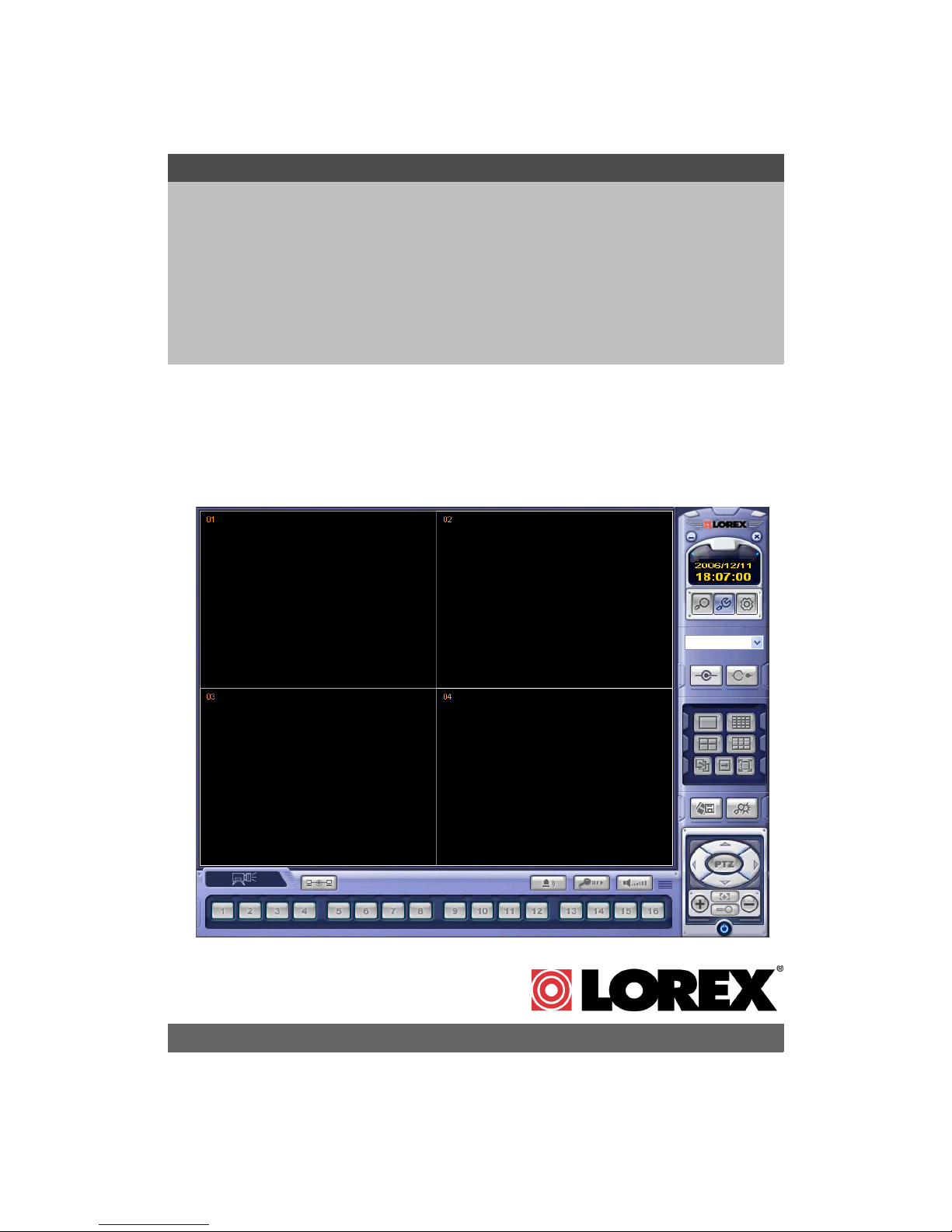
About the Lorex Client
The Lorex Client software package allows you to access your DVR from a remote location to
view live and previously recorded video.
• View and Record from your PC - Connect your DVR to your Network
• Minimum System Requirements: Windows XP, Pentium 4 processor with 256MB RAM (512MB
RAM recommended)
The Lorex Client Software is now Microsoft Windows Vista™
compatible. Visit us on the web at www.lorexcctv.com/support
to download the Vista™ Compatile software version.
Please visit us on the web for the most current Manuals, Quick Start
Guides and Firmware. Additional Language Manuals are also available at:
http://www.lorexcctv.com
2
Page 3
System Requirements
System Requirements
The Lorex Client software (included with the DVR) has the following installation requirements.
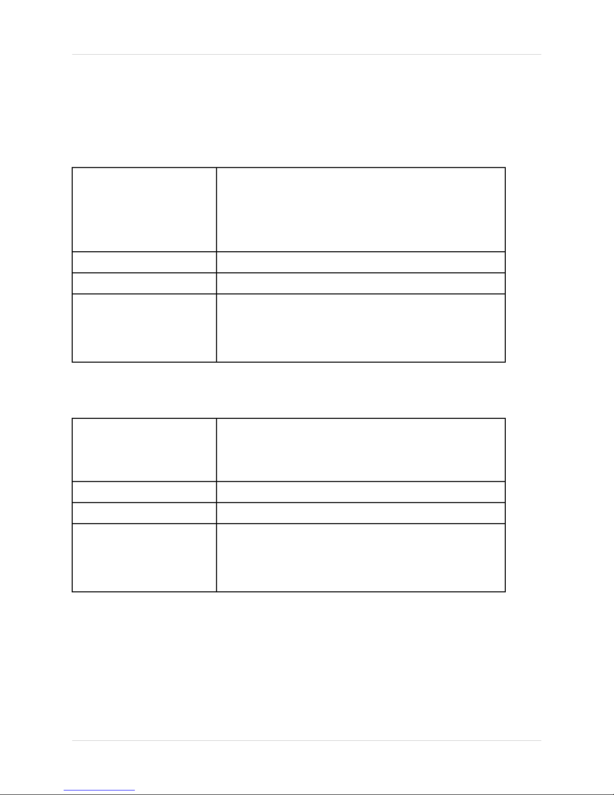
Minimum System Requirements:
Operating System Windows 2000
Windows XP Home Edition
Windows XP Professional
Windows Vista
Processor .Pentium 4 - 1.5 GHz Processor (or equivalent)
Memory 256 MB RAM (512 Recommended)
Hard Drive 50 MB - Installation space required
* Additional Hard Drive space required for recording.
Recorded file size will vary depending on recording
quality settings
Recommended System Requirements:
Operating System Windows XP Home Edition
Windows XP Professional
Windows Vista
Processor Pentium 4 / 3 GHz Processor (or equivalent)
Memory 1024 MB RAM
Hard Drive 50 MB - Installation space required
* Additional Hard Drive space required for recording.
Recorded file size will vary depending on recording
quality settings
Please refer to the Lorex Client Software User Guide included with your DVR for further details.
Visit the Lorex support website at http://www.lorexcctv.com for information on Windows Vista
compatibility.
3
Page 4

Software Installation
Software Installation
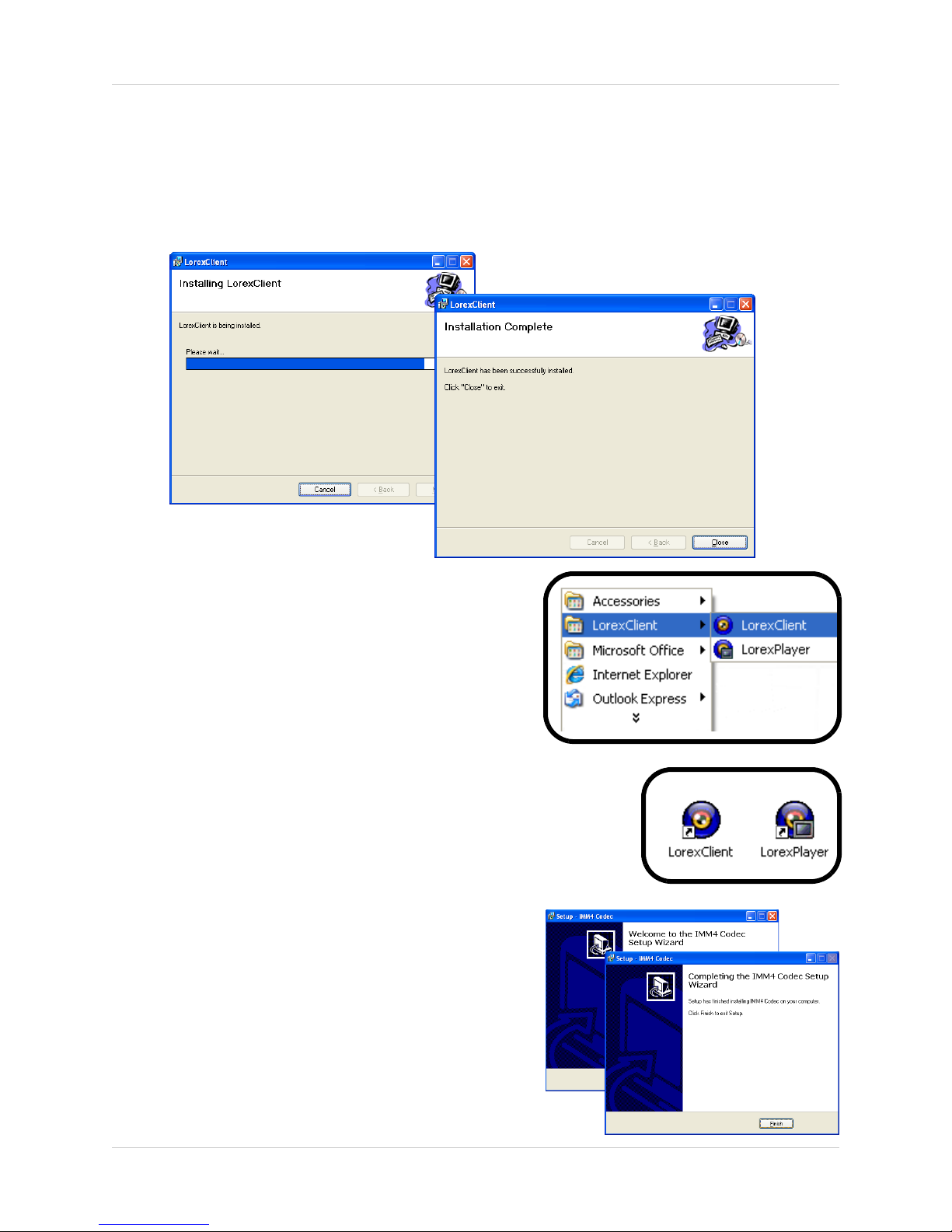
Place the Lorex Client Installation CD in the CD-ROM Drive of your Computer. The Software
Install Wizard for the Lorex Client Software will begin.
1. Click the NEXT button on both dialogue windows to continue the Installation:
NOTE: If the Installation Process does not automatically start, you will have to begin the
installation process manually:
• Double Click the MY COMPUTER icon on your Desktop
• Double Click the CD-ROM DRIVE (Drive Letter will vary depending on the number of drives
in your computer)
• Double Click the SETUP.EXE file (may appear as SETUP with no file extension,
depending on your system settings.
The Installation Process will begin.
4
Page 5
Software Installation
Software Installation
Place the Lorex Client Installation CD in the CD-ROM Drive of your Computer. The Software
Install Wizard for the Lorex Client Software will begin.
1. Click the NEXT button on both dialogue windows to continue the Installation:
NOTE: The following Program Shortcuts will be created:
• Start Menu - Programs - Lorex Client
z Lorex Client
z Lorex Player
• Desktop Shortcuts for:
z Lorex Client
z Lorex Player
Installing the Codecs
To playback the recorded AVI files, the Video Codec
needs to be installed:
1. Run the CODEC.EXE file located on the Software CD
2. Accept the default propts during the installation, and
click the Finish to complete.
5
Page 6
Lorex Client Software - Main Screen
Lorex Client Software - Main Screen
4
1
2
3
5
6
7
8
9
10
11
12
13
14
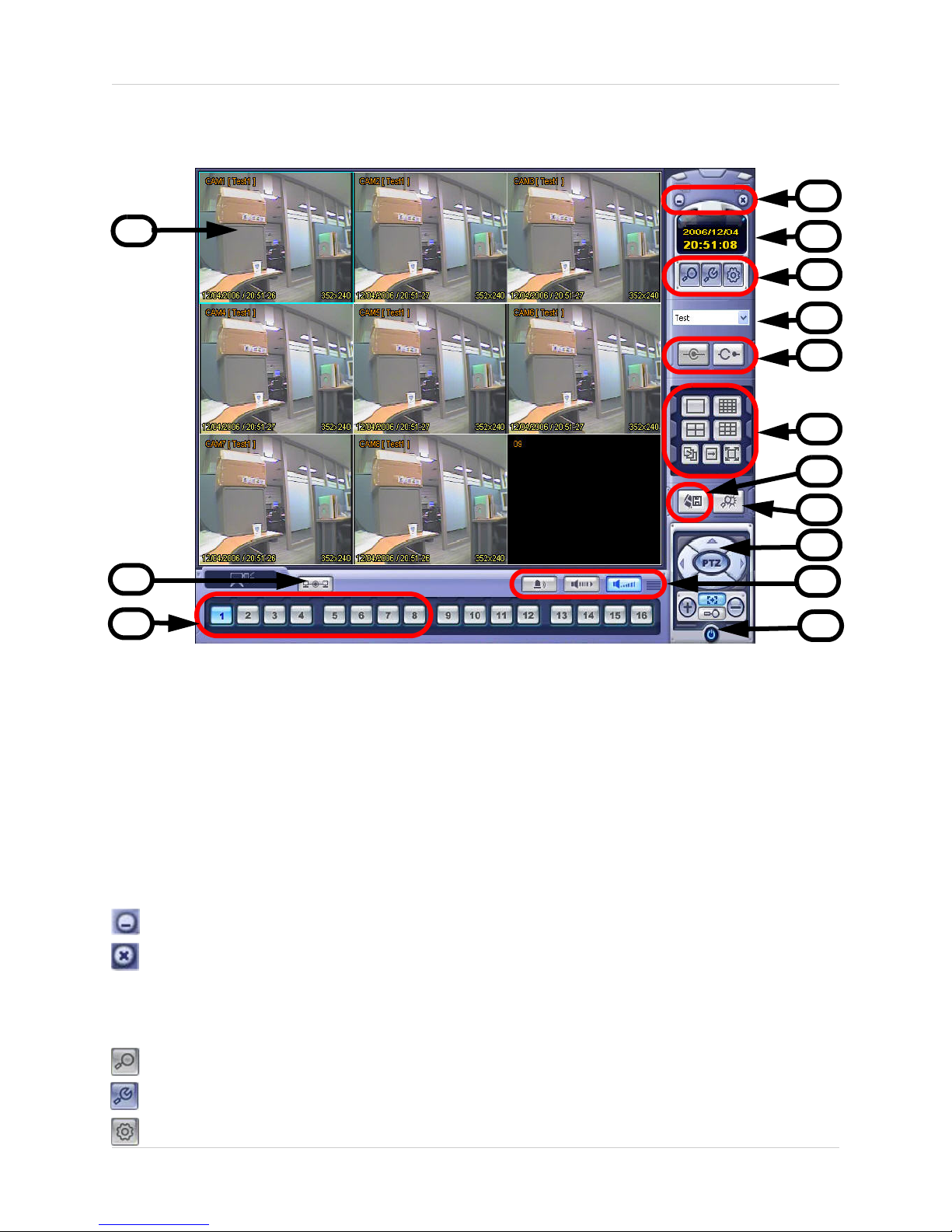
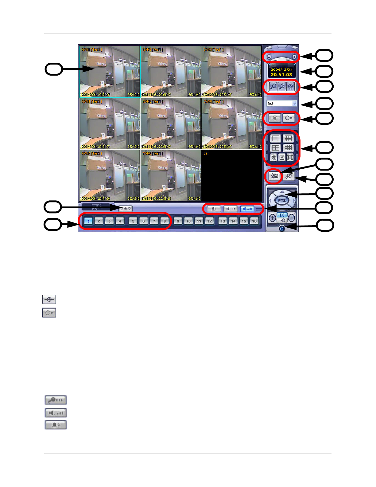
1. Main Screen - Displays live Camera images (delays in images are due to Network speed and
connectivity strength).
2. Connection Status - Displays the DVR connection status.
3. Camera Selection Buttons - Displays the Connected Camera Number. Press buttons 1~8 to
select a Camera Number for display.
4. Minimize / Exit -
• Minimizes the Client Window
• Exit Program.
5. Time Display - Shows the current Time & Date.
6. Search / Setup Buttons -
• Search Mode - Search for previously recorded video.
• Connection Manager - Configurations for Network Connection and Local Recording.
• Remote DVR - Changes the setup on the remote DVR.
6
Page 7
Lorex Client Software - Main Screen
4
1
5
6
7
8
9
10
11
12
2
3
13
14
7. DVR Selection - Select the Connection ID for the DVR.
8. Connect / Disconnect Buttons -
• Connect: Connect to the DVR.
• Disconnect: Disconnects from the DVR.
9. Screen Display - Changes the Screen View (Single, Quad, 9, Full screen or Tiled).
10. Save to File - Saves the currently displayed video to an AVI file on the local PC.
11. Event viewer - Displays the Event List and Image Search functions.
12. PTZ Control Button - Controls Cameras with PTZ & Focus configured (refer to the Instruction
Manual for the DVR).
13. Alarm and Audio Buttons -
• Mic.
• Speaker Volume
• Alarm On/Off.
14. Exit - Closes the Lorex Client software.
7
Page 8
Connection Manager
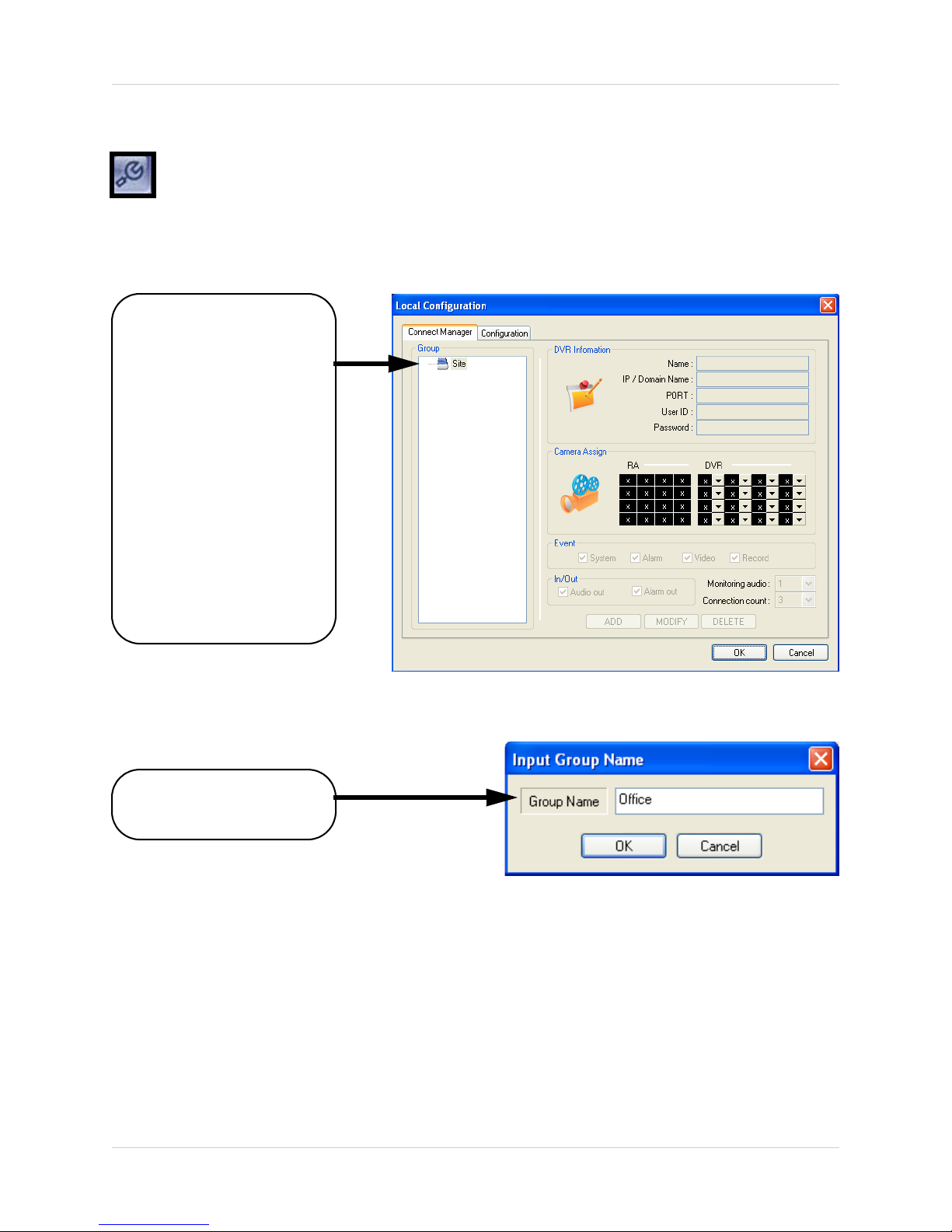
Connection Manager
The Connection Manager contains the setup information to allow the user to remotely
connect to the DVR.
Adding a Group
Group - Right click on
‘Site’ to add a New Group.
A group can represent
one or more DVRs.
For Example, you may
have more than one
system in your office, so
would name your group
‘OFFICE’.
Each individual unit can
then be configured
separately for connection.
Enter a name for the
Group.
8
Page 9
Adding a Site (Individual Unit Configuration)
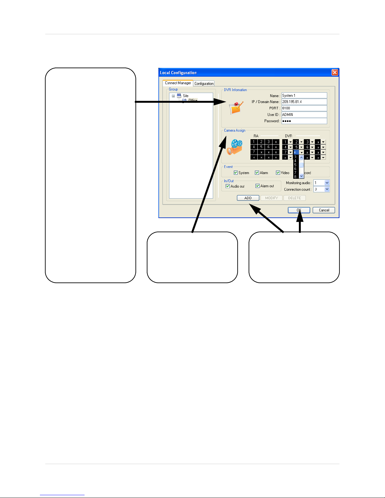
DVR Information - Enter
the information specific to
the unit (refer to page 30
for setup instructions):
• Name - Enter a name for
the unit.
• IP / Domain Name Enter the IP address or
Domain Name for the
System. This will vary
depending on setup
(Internal Network
Connection or External
Remote access through
the Internet)- refer to page
30 for setup details.
• Port - Set to 6100 by
default.
• User ID - Enter the USER
ID to connect to the system
(the USER ID is configured
on the System - i.e. ADMIN
- case sensitive).
• Password - The
password used to access
the System (i.e. The
ADMIN password is set to
1234 by default).
Camera Assign - Set
each camera to a portion
of the 9-view window by
using the drop down
menu selections.
Connection Manager
ADD Button - Adds the
site to the Group.
OK Button - Accepts the
changes and Closes the
configuration Window
9
Page 10
Connection Manager
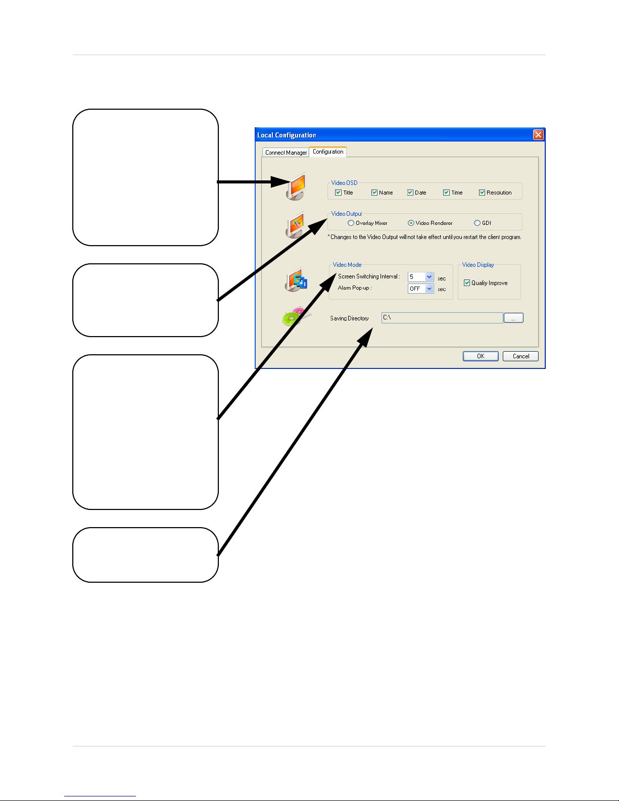
Configuration Tab
Video OSD - Sets the
display options for the
Video:
• Title -
• Name - Displays the
name of the Camera
• Date - Displays the date
• Time - Displays the time
• Resolution - Displays
the video resolution
Video Output - Sets the
Video Output type to
Overlay Mixer, Video
Receiver or GDI.
Video Mode - Sets the
Video Mode:
• Screen Switching
Interval - Sets the screen
switching time for
Sequence view.
• Alarm Popup - Sets the
Display popup when an
Alarm is detected on the
system
• Quality Improve Adjusts the Video quality
Save Directory - Browse
to set the default save
location for Video images.
10
Page 11
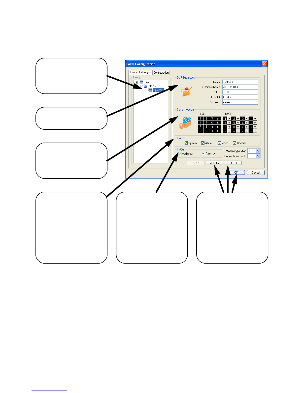
Modifying a Site
Left click on the selected
Site (from the Group
Listing) to access the
settings.
DVR Information - Can
be changed if desired.
Camera Assignments Camera default positions
can be reassigned if
desired.
Connection Manager
Event Selection - Selects
the types of Events:
• System
• Alarm
• Video
• Record
For detailed information
on Events, refer to the
System Instruction
Manual.
IN/OUT Selection - Sets
the Audio and Alarm out.
• Audio Out - Sends Audio
to the System
• Alarm Out - Sends Alarm
to the System
• Monitoring Audio - Sets
the default channel for
Audio Monitoring.
• Connection Count Maximum connections.
MODIFY Button - Saves
changes to the Site
configuration.
DELETE Button Deletes the site from the
Group Listing
OK Button - Accepts the
changes and Closes the
configuration Window
11
Page 12

Remote Connection
Remote Connection
Once the site setup profile has been created, a connection can then be made to the DVR:
1. Select the Site profile
from the Dropdown List.
2. Press the CONNECT
button.
The Connection Status
window displays the state
of the connection.
Once a successful
connection to the System
has been made, the black
screen view will switch to
Live Camera View mode.
NOTE: If another user is
connected to the System
using the same
credentials (i.e ADMIN),
the connection will be
rejected.
12
Page 13

Remote Observation Setup
The Remote Observation Setup allows the user to make changes to the remote system.
Entering the System Password
Checking Authority - To
change the Remote
System Settings, the user
is required to re-enter the
ADMIN password, and
press OK.
Remote Observation Setup
Recording Setup - Simple
• Record Mode - Select the Recording
Setup type (Simple or Advanced
configuration).
• Camera Group - Select Cameras
1~4 or 5~8 for setup.
• Record Quality - Sets the Recording
Quality. Select HIGHEST, HIGH,
STANDARD or LOW.
• Record Size - Sets the Recording
Size (video display). Select
352x240, 704x240 or 704x480.
• Record Frame Number - Sets the
Recording Frame Rate. Select 1, 2,
3, 7 or 15 FPS
• Use the Mouse to select or deselect
Schedule options (Blue Highlighted
blocks indicate that the segment is
Selected).
13
Page 14

Remote Observation Setup
Recording Setup - Advanced
Select the Advanced option from the
Record Mode dropdown menu. An
window will appear to indicate that the
Mode has changed.
• Camera Group - Select the Channel
Area (CH1~4 or CH5~8)
• Schedule Mode - Set to Weekly or
Daily. When the System is set to
weekly mode, set each day
individually
• Pre Event Recording Time - Sets
the Pre-Event Recording Time
(between 0 ~ 5 Seconds). The
Pre-Event records the data that
occurred before the Event occurred.
Refer to the DVR Instruction Manual
for more details.
• Post Event Recording Time - Sets
the Post-Event Recording Time
(between 5 ~ 180 Seconds). The
Post-Event records the data that
occurred after the Event occurred.
Refer to the DVR Instruction Manual
for more details
• Alarm / Continuous / Motion
Record Setup - Click the “Set”
Button to setup the Cameras for
Alarm, Continuous and Motion
Recording: Set the Size, Recording
Rate. Quality and Audio for each
camera. Press OK to save the
Settings.
• Alarm / Continuous / Motion
Recording Schedule - Use the
mouse to select individual time
blocks for Alarm, Continuous and
Motion Recording. Selected blocks
are displayed in Blue.
14
Page 15

Camera Setup
Settings for Individual Camera recording
• Camera Group - Select Cameras
1~4 or 5~8 for setup.
• Covert / Title - Sets the Covert status
and Name for each camera. Refer
to the DVR Instruction Manual for
more details on the Covert Camera
Setting.
• Color Setup - Sets the Brightness,
Contrast, Tint and Color for each
camera.
• PTZ Setup - Set the Address, PTZ
Protocol and Baud rate for each
camera. Click the Properties button
to enter additional setup
information. Refer to the specific
PTZ Camera Manual for details on
configuration.
Remote Observation Setup
• Motion Area - Click the “Camera”
Button to access the Motion Setup
Menu. Select an area by click and
dragging with the mouse. The
Selection menu will automatically
appear to Select/Deselect/Cancel
the Motion Setup.
15
Page 16

Remote Observation Setup
Sound Setup
• Live Audio - Sets Live Audio to ON/
OFF.
• Audio monitoring channel - Sets
the channel for Live Audio
Monitoring (1~4 Only).
• Network Audio TX - Sets the
Network Audio transmission to ON/
OFF.
• Network Audio RX - Sets the
Network Audio Receive to ON/OFF.
• Buzzer Setup - Turns the alarm
buzzer OFF when a button is
pressed on the System Front Panel
Keypad.
16
Page 17

Event/Sensor Setup
• Alarm Input - Sets the Alarm Input
Operation to Enabled or Disabled,
and sets the Type to Normally Open
or Normally Closed. Refer to the
DVR Manual for details on
configuration of External Alarm
devices.
• HDD Event - Turns the Alarm On/Off
when a problem is detected with the
System Hard Drive.
• Alarm Out - Sets the Alarm out for
a secondary Alarm Device. Refer to
the DVR Manual for details on
configuration of External Alarm
devices.
• Operation: Set the Relay
Connect with Alarm Sensor to
ON/OFF.
Remote Observation Setup
• Mode: Set the Reacted Relay to
Latched or Transparent Mode.
• Type: Set to Low (Normally
Closed) or High (Normally
Open)
• Duration: Setup Reacted Relay
Time. (5sec~5min or Until
key-in)
• Buzzer Out - Sets the audible buzzer
alert when an event is detected.
• Buzzer: On/Off
• Duration: Sets the Buzzer time
(5sec~5min or Until key-in).
• Mode: Setup Reacted Relay as
Latched/Transparent Mode.
• HDD Event: Alarm On/Off when
HDD has the problem.
• E-mail Notification - Generates an
email notification when an Event is
detected. Refer to the DVR Manual
for details on configuration of Email
Notification.
17
Page 18

Remote Observation Setup
System Setup
• System Info - Displays the System
Information including the Software
and Hardware versions, Video
Signal type, IP and MAC addresses,
and Disk Space usage.
• SMTP - Setup the mail server and
user’s E-mail (for email send on
Event notification):
• Server: The Internet Provider for
Email Sending
• Port: Default port 25
• User: Enter the User ID used by
the Internet Provider for
Internet connectivity.
• Password: Enter the Password
used by the Internet Provider
for Internet connectivity.
• Security: Set the security.
• Users - Setup/Modify System Users
by pressing the “Add” or “Modify”
buttons.
• Network Speed - Set the network
connection speed.
• Disk Overwrite - Sets the DVR HDD
Overwrite On/Off.
• Record Time Limit - Select the time
(Off, 12 hours, 1day, 2day, 3day,
1weeks or 1month)
18
Page 19

Display Setup (Screensaver)
• Auto Brightness - select the time
(10 min., 20min, 30min, 40min,
50min or 1 hour). If a time is set, the
Remote System screen will go dark
after the set time interval.
• Main Display Off - Turns the main
System screen On/Off during
specified times:
• From: Main Display Off start time
• To: Main Display Off end time.
• * If selecting the “Off”, “main
display off function” does not
work.
Remote Observation Setup
19
Page 20

Remote Monitoring
Remote Monitoring
Once the site setup profile has been created, a connection can then be made to the DVR:
1. Select the Site profile
from the Dropdown List.
2. Press the CONNECT
button.
Screen View Controls
Single Camera View
Quad View
Sequence Mode
16 Camera View
8 Camera View
Full Screen View
Manual Switch Mode
20
Page 21

PTZ Controls
Press the PTZ Button to access the extended PTZ Menu:
P/T/Z Controller - Move
the Camera Pan/Tilt using
the Direction Keys
FOCUS/ZOOM Select
Button - Controls the
Focus or Zoom Control
using the + and - Buttons
Remote Monitoring
AVI File Conversion
• Press the AVI (Video)
Save Button to start
Video Recording to the local PC
• A dialogue box will appear while
video is saving. Press STOP to end
the video.
• A second dialogue box will appear,
indicating the saved files. The files
are saved in the default location
specified in the System Setup.
21
Page 22

Remote Monitoring
Event Viewer
• No - Event order number
• DVR - Indicates the DVR name
where the event originated.
• CH - Indicates the channel where the
event occurred (if applicable)
• Time - Displays the Time and Date
that the event occurred at.
• Description - A description of the
event type.
22
Page 23

Search Functions
The Remote Observation Setup allows the user to search for video and events.
1
Search Functions
3
4
5
2
1. Search Screen - Displays the Selected Video.
2. Search Bar - Search & Display Camera Recording Times (24 hours).
3. LIVE Button - Return to Live Viewing Mode
SETUP Button - Access system settings.
4. Screen Layout - Change the display screen view.
5. SEARCH - Backup Video or Search for Events.
6. Camera Selection Button - Select individual cameras.
6
7
8
7. Quick Search - Find information by Date & Time.
8. Search Controller - Video playback controls
23
Page 24

Search Functions
Event Viewer
Indicates
0~24 hour
Time
Search Bar - Drag to
select the recording time.
Indicates Recording Status:
Grey (No Recording) and
White (Recorded Data).
Displays the
Camera recording
channel
Channel Bar - Scroll to
select different cameras.
Volume
Control
Search By Time
Select date and Time
Video Playback
Controls: Play video in
normal speed (Play
and Reverse
Playback)
Change Playback
Speed (up to 64x
Forward and Reverse)
24
Page 25

Search Options
Archive
Copies a backup of the video data from the DVR to the local PC.
• Time Range - Set the start and end
times for backup.
Search Functions
• Channel - Select channels to
Backup.
• Include Audio - Includes Audio with
the video backup.
Press OK to start the backup. A status
window will appear for the backup
process.
Once complete, the window will
disappear and the data will be saved in
the designated folder.
25
Page 26

Search Functions
Backup Play
Plays back previously saved video data:
Video Playback Image
(only one camera can be
displayed at a time)
Select the Date and Time
for the video playback
Playback Controls (See
previous Search options
for details).
Image Save Function
• Click the ‘Save Image’ Icon during
Video Playback.
• Enter a file name, select a File Type
(JPG or BMP), and Location. Press
the SAVE Button.
• The current image will be saved.
Displays the currently
displayed file name.
Total playback time for
the video recording.
26
Page 27

Print Function
• Prints the currently displayed image.
Select the Printer, and press OK.
Search Functions
Log Viewer
Search Range -
Set the Start Date
and TIme, and
End Date and
Time.
Logs -
Displays logs
(based on Search
Range and
Search
Conditions).
Displays the Log
Number, Channel,
Date and
Search Button Press to perform a
search based on
Criteria
Search
Condition -
Select the Search
criteria (Alarm,
Motion,
Continuous or
System).
OK Button
Move to Previous or Next Page, or
use the dropdown to select a
specific page number.
Return to Timeline View
(Search Mode).
27
Page 28

Search Functions
Event Viewer
Displays a list of all Events.
• NO - Event Number
• DVR - Displays the DVR
where the event originated
from.
• CH - Displays the channel
number where the event
occurred (if applicable.
Some event types will not be
display a Channel number)
• Date and Time - The date
and time that the event
occurred
• Description - Displays a
description of the Event
type.
28
Page 29

Web Client
Web Client
Once the System is configured, a connection can be made using Internet Explorer (only
supported Web Browser).
• Enter the IP Address or DDNS Address of the DVR in the Address Bar of Internet Explorer.
• A prompt will appear for Active-X - choose to install the controls.
• The Lorex Client software will install remotely, and have the same functionality as the full
installation (from CD).
29
Page 30

Network Setup / Remote Access Overview
Network Setup / Remote Access Overview
The SG19LD804-161 DVR can be remotely controlled using your existing network and the Lorex
Client software.
1. Connect the DVR to the Router using the supplied Ethernet Cable. Power the DVR on.
NOTE: The DVR must be connected to the router prior to powering on the system. This
allows the system to communicate on your network
2. Find the IP address of your DVR through the Menu System on the unit.
3. Set up a web account at http://DDNS.strategicvista.net
4. Enable PORT FORWARDING on your Router. Refer to the included Router Guide and Basics
of Remote Video Access Guide for further assistance with your specific network setup and
hardware.
5. Setup the DVR DDNS (based on information setup on the DDNS website in step 3).
6. Install the Software on your PC. Configure the software as outlined on page 8 of this manual,
using the information gathered on the following pages.
DVR
.
INTERNET
30
ROUTER
(Not Included)
PC
(Not Included)
Page 31

IP & MAC Address
The IP & MAC Addresses are necessary
for DDNS Setup (for remote access to
the DVR).
Network Setup / Remote Access Overview
IP Address
To Locate the System information, Press
the ENTER button on the Front Panel or
Remote Control while viewing the
Cameras. The System Info window will
be displayed.
- OR -
1. Press the Menu Button on the Front
Panel or Remote Control to access the
Setup Menu. Select the System Setup
option and press the Enter button.
2. Navigate to the System Menu option.
Press the Enter button to access the
System Menu.
3. Navigate to the System Management
menu, and press the Enter Button to
access the settings.
4. Select the System Information option,
and press the Enter Button to display
the System Settings.
MAC Address
Finding Your External IP Address
You will need to have your External IP address to set up your DDNS account. One of the fastest
ways to find this information is to use a 3rd Party website such as http://www.showmyip.com
Your IP address can also be found within your Router settings. Refer to your router user guide for
further details.
IP Address
MAC Address
31
Page 32

Network Setup / Remote Access Overview
Setting Up Your DDNS Account
Lorex offers a free DDNS service for use with your System. A DDNS account allows you to set up
a web site address that points back to your Local Network. The following outlines how to set up
your free DNS account.
1. Navigate to http://DDNS.strategicvista.net
2. Select the Create Account option from the list on the left side
of the screen.
3. Complete the Account Information fields with your personal information
4. Complete the System Information fields:
• Product License: Select your product model from the
Product License drop down menu
• <Product Code> - <MAC Address>: Locate the MAC
address of your (recorded while loading the System)
• URL Request: Choose a URL for your DDNS connection
(i.e. your name, your company or business name, or
anything of your choice.)
32
Page 33

Network Setup / Remote Access Overview
1. Click the Create New Account link at the bottom of the form to submit your request.
2. Your Account information will be sent to you at the E-mail Address you used in Step 3.
Service provider:
User Name:
Domain Name:
Password:
dns1.strategicvista.net
tomsmith1
tomsmith
(your password)
You will need this information for remote access to your System. Record YOUR
below:
User Name:
________________________________________________________ *
Domain Name:
__________________________________________________________
information
Password:
__________________________________________________________
* Only the first part of the Domain Name is required for setup on the
SG19LD804-161 System. If the full Domain sent is tomsmith.strategicvista.net, the unit only requires that only tomsmith be entered.
33
Page 34

Network Setup / Remote Access Overview
Router Port Forwarding
You will need to enable port forwarding on your Router to allow for external communications with
your DVR for ports:
• TCP/IP PORT 6100
• WEB PORT 80
Computers, DVRs, and other devices inside your network can only communicate directly with
each other within the internal network. Computers and systems outside your network cannot
directly communicate with these devices. When a system on the internal network needs to send
or receive information from a system outside the network (i.e. from the Internet), the information
is sent to the Router.
NETWORK EXAMPLE
Router
External IP
216.13.154.34
Router
Internal IP
192.168.0.1
Computer
Internal IP
192.168.0.2
Observation
System
Internal IP
192.168.0.3
Internet
Internal Network
When a computer on the Internet needs to send data to your internal network, it sends this data
to the external IP address of the Router. The Router then needs to decide where this data is to
be sent to. This is where setting up Port Forwarding becomes important.
Port Forwarding tells the router which device on the internal network to send the data to. When
you set up port forwarding on your Router, it takes the data from the external IP address:port
number and sends that data to an internal IP address:port number (i.e Router External IP
216.13.154.34:6100 to DVR Internal IP 192.168.0.3:6100).
The instructions found online in the Router Configuration Guide
forwarding configurations for a selection of different router models.
Visit our Consumer Guides Support
34
will assist you in the port
website at http://www.lorexcctv.com for more details
Page 35

DDNS SETUP
Once the DDNS settings have been
configured online, the information must be
entered on the DVR to allow for remote
connection via the Lorex Client Software (or
through Internet Explorer):
1. Access the Main Menu Setup screens, and
navigate to the SYSTEM option. Press the
ENTER button to access the setup.
2. Navigate to the NETWORK option. Press
the Enter button to access the Network
settings. Select the DDNS Server option,
and press the ENTER button to enter the
DDNS SETUP.
Network Setup / Remote Access Overview
3. Enter the information received in email
(including the password). Press the DDNS
Status first - wait for the SUCCESS
MESSAGE (as long as the information is
correct).
Select OK to save the settings.
NOTE: Once all Network settings are configured, the System can be accessed using
the Lorex Client Software. Refer to Page 8 for Connection Manager details.
35
Page 36

It’s all on the web
Product Information
User Manuals
Quick Start Guides
Specification Sheets
Software Upgrades
Firmware Upgrades
VISIT
www.lorexcctv.com
LOREX Technology Inc.
wwwlorexcctv.com
 Loading...