

Page 1
Dial Up V
ideo Server
L4204T
Page 2
Lorex Dialup Video Server User’s Guide
2
Notice
The information in this document is subject to change without prior notice in order to improve reliability,
design, or function and does not represent a commitment on the part of this company.
In no event will we be liable for direct, indirect, special, incidental, or consequential damages arising out of
the use or the inability to use the product or documentation, even if advised of the possibility of such
damages.
Copyright © 1997 - 2004 Strategic Vista Technologies Inc.
All Rights Reserved.
No part of this reference manual may be reproduced or transmitted in any form or by any means without
the prior written permission of this company.
Throughout this manual, we make reference to product names that are trademarks of other companies.
We are using these names for identification purposes only, with no intention of infringement of the
trademarks.
FCC Information
This equipment has been tested and found to comply with the limits for a Class B digital device, pursuant
to Part 15 of the FCC Rules. These limits are designed to provide reasonable protection against harmful
interference in a residential installation. This equipment generates, uses and can radiate radio frequency
energy and, if not installed and used in accordance with the instructions, may cause harmful interference
to radio communications. However, there is no guarantee that interference will not occur in a particular
installation. If this equipment does cause harmful interference to radio or television reception, which can
be determined by turning the equipment off and on, the user is encouraged to try to correct the
interference by one or more of the following measures:
• Reorient or relocate the receiving antenna.
• Increase the separation between the equipment and receiver.
• Connect the equipment into an outlet on a circuit different from that to which the receiver is
connected.
• Consult the dealer or an experienced radio/TV technician for help.
Shielded cables and I/O cards must be used for this equipment to comply with the relevant FCC
regulations.
Changes or modifications not expressly approved in writing by Strategic Vista Technologies Inc. may void
the user's authority to operate this equipment.
Page 3

Lorex Dialup Video Server User’s Guide
3
Table of Contents
1. GENERAL INFORMATION ..................................................................................5
1.1 INTRODUCTION...................................................................................................... 5
1.2 TECHNICAL SPECIFICATION..................................................................................... 7
1.3 SYSTEM REQUIREMENTS......................................................................................... 7
2. REMOTE UNIT INSTALLATION.........................................................................9
3. SOFTWARE INSTALLATIO N.............................................................................12
4. UNINSTALLATION.............................................................................................13
5. USING THE CLIENT SOFTWARE.....................................................................14
GETTING STARTED WITH LOREX DVS CLIENT PROGRAM....................................................15
5.1.1 Main control panel........................................................................................16
5.1.2 Getting initial images from DVS .....................................................................17
5.1.3 Image window description ..............................................................................21
5.2 CONFIGURING THE REMOTE DVS UNIT ...................................................................23
5.2.1 Modifying basic and image parameters...........................................................23
5.2.2 Setting up Callback parameters......................................................................25
5.2.3 Changing external modem parameters ............................................................ 29
5.3 MOTION DETECTION CONTROL ..............................................................................31
5.4 RELAYS AND SENSORS CONTROL ............................................................................32
5.5 INTERNAL IMAGE MEMORY MANAGEMENT..............................................................33
5.6 CONTROLLING PAN, TILT, ZOOM, FOCUS OF REMOTE CAMERAS...............................35
5.7 AUDIO STREAM CONTROL......................................................................................37
5.8 COMPACTFLASH MANAGEMENT.............................................................................39
5.9 PREPARING AND USING CALLBACK MODE WITH MOTION AND SENSORS ALARM
DETECTION......................................................................................................................42
5.10 DVS PROGRAM COMMANDS IN DETAIL................................................................45
5.10.1 Additional dialing options..............................................................................45
5.10.2 Changing and memorizing the DVS password.................................................48
5.10.3 Retrieving software and firmware versions......................................................50
6. DVS OPERATION MODES..................................................................................51
6.1 INTERNAL MODEM MODE.......................................................................................51
6.2 DIRECT CABLE CONNECTION (COM PORT) MODE ....................................................51
6.3 CUSTOM CONFIGURATION (EXTERNAL MODEM ) MODE.............................................53
Page 4

Lorex Dialup Video Server User’s Guide
4
7. TROUBLESHOOTING.........................................................................................54
7.1 HOW TO GET SOFTWARE UPDATES AND TECHNICAL SUPPORT ...................................54
8. WARRANTY PAGE………………………………………..………………….………55
Page 5

GENERAL INFORMATION
Lorex Dialup Video Server User’s Guide
5
1. GENERAL INFORMATION
1.1 Introduction
Thank you for purchasing the LOREX product. The Dialup Video Server (DVS) will enable you
to monitor sensitive locations and remote areas over standard phone lines. A key feature of
DVS is the ability to not only visually survey a sensitive location, but to also hear what is
occurring at the scene as well as speak to anyone at the monitored location. A standalone DVS
unit installed on-site with video and audio feed from up to four cameras and connected to a
phone line lets you see and hear exactly what is happening and verbally interact with the
individuals at the sight.
No special hardware is required at the operator's PC, just a modem. Images are transmitted by
the remote DVS unit will be decoded by a special client software and displayed on the screen or
stored onto a hard disk for later examination. The operator, who can be located several
thousand miles away, is in complete control of the DVS and any cameras attached to it . This
allows for incredible expandability and flexibility of the security and surveillance network.
Important features of DVS-based surveillance system include:
• DVS is low cost, maintenance-free standalone unit.
• High quality Wavelet-compressed video from 4 sources and one channel full duplex
audio can be transmitted simultaneously between DVS and supervisor’s PC through an
ordinary phone line (POT line) using internal PSTN modem at a bit rate up to 56Kbps.
• Optional connection types supported: External PSTN modem, ISDN modem, cellular
services (GSM, CDMA modem), dedicated line modems and direct cable connections.
• DVS unit and PC client software are specifically designed for extremely low speed
connections, giving the user surveillance capability approaching real-time. Maximum
achievable video update rate for one camera source with a 28.8 kbps modem connection
at a resolution of 170x120 is 5 frames per second.
• Snapshots – high quality/resolution images can be captured into internal DVS memory
at operator’s request, while monitoring an area with low quality/resolution but high frame
rate.
• Audi o user interface provides full control in audio streaming mode.
• Non-volatile internal video memory plus CompactFlash (removable) are used as video
storage.
• Callback mode: DVS unit can be instructed to call a PC back and notify you about
suspicious activity in the monitored area or alarm events on sensor’s inputs, and show
high quality captured snapshots sequence (user defined) on the screen which can be
automatically saved as a JPG or AVI file without any user interaction.
• Motion Detection is provided with adjustable sensitivity levels and camera
participation in a motion monitoring cycle for every camera.
• Password protection is available to prevent unauthorized access.
• Internal timer for pictures time stamp.
Page 6

GENERAL INFORMATION
Lorex Dialup Video Server User’s Guide
6
• Camera Pan/Tilt/Zoom (PTZ) control for certain camera models: SONY EVI-G20,
SONY EVI-D30, KALATEL, PHILIPS TC-700 and DCP -1010 (Pelco-D) etc.
• Can be optionally connected to Windows-based WWW server to make JPEG images
available through the web browser.
DVS will become an important part of your personal or corporate security video and audio
surveillance system.
Page 7

GENERAL INFORMATION
Lorex Dialup Video Server User’s Guide
7
1.2 Technical specification
• 4 BNC composite video inputs (1 Vp-p/75 Ohm)
• One full duplex audio channel: Microphone/Linear and Speaker jack’s connectors
provided for external electret-foil microphone and speaker.
• 2 RS-232 ports (male). One RS-232 is for external modem and another for PTZ
function support.
• 8 inputs (TTL level) for external alarm sensors.
• 4 relay outputs (0 - 400V AC/DC, 120 ma) that can operate on alarm events: sensors
toggling, motio n detection, video loss.
• Onboard memory: 512 KB for compressed video buffering (non-volatile). Approximate
storage capacity: 50 snapshots of good quality at 340x240 resolution.
• CompactFlash socket – memory card can be used as an optional expanded removable
storage.
• Video Input Type: NTSC, PAL, B/W 60 Hz, B/W 50 Hz.
• Video Resolution: 680x480, 340x240, 170x120.
• Video Compression: Wavelet.
• Audio Compression: G723.1 5.3 Kbps.
• Dimensions: 310mm x 140 mm x 56 mm. (12.20" x 5.51" x 2.20")
• Power consumption: +12V/0.5A (requires external power supply 1.2A recommended).
• Operating temperature: 0°C ~ +50°C (system is designed for in -door use)
1.3 System requirements
The following are minimum system requirements for an operator’s PC sufficient to run Lorex
DVS client sof tware:
• Desktop or notebook PC with Intel Pentium™ 90 MHz or compatible CPU.
Pentium II™ MMX™ 300 or better CPU is recommended for optimal system
performance.
• 32 MB of system RAM (64MB for Windows NT).
More memory is recommended for improved overall system performance.
• Microsoft® Windows® 95, Windows® 98, Windows NT™ 4.0, Windows® 2000,
Windows® XP.
• Any Windows-compatible modem (internal or external) . 57.6 Kbps modem is
recommended.
Page 8

GENERAL INFORMATION
Lorex Dialup Video Server User’s Guide
8
• Display adapter configured for 16-bit or better color mode (32768 or more colors)
at 800x600 or higher resolution.
• 5 MB of free space on system hard disk are required for standard software installation.
Additional free space is required to store individual still images and image sequences.
The rest of this document contains important installation and operating instructions for DVS
hardware (remote unit) and the client software on the operator’s PC. Be sure to read all
applicable sections carefully before proceeding.
Page 9
REMOTE UNIT INSTALLATION
Lorex Dialup Video Server User’s Guide
9
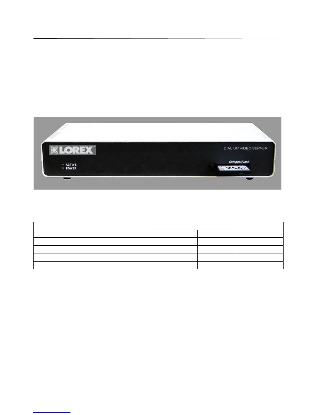
2. REMOTE UNIT INSTALLATION
This chapter describes installation procedure of the remote video surveillance unit that is the
essential part of the DVS package. The remote DVS unit is a standalone device that does not
need any direct connection to a PC on remote monitoring site. The unit’s exterior is shown in
Figure 1.
Figure 1 DVS unit front view
The remote unit should be placed on the site that requires monitoring, anywhere within the
reach of a telephone line. It is recommended to place the DVS unit as near to the video cameras
as possib le to avoid image quality degradation or use of expensive high-grade video cables.
Maximum video cable length is 100 meters and may vary depending on cable quality.
• First, you should check DVS unit CONFIGURATION in order to make appropriate DIP -
switch SW settings on the back panel of unit (see Figure 2). All possible operation modes
are tabulated:
SW position
Operation Mode
Internal modem
Aux mode
Reference for
details
Internal modem (standard) ON OFF Section 6.1
Direct cable connection (COM-port) OFF ON Section 6.2
Custom configuration (external modem) OFF OFF Section 6.3
Auxiliary (reserved) ON ON -
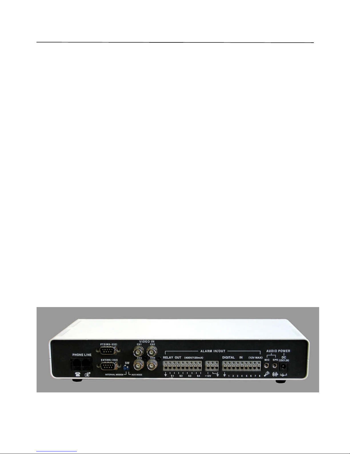
• Provided that you will use device with internal modem configuration, connect the telephone
line (RJ11 plug) to the Line connector on your DVS unit (see Figure 2). If the same line is
also to be used for as a regular telephone line or to connect a fax machine, then use the
Phone connector on the DVS. In that case, you may need to adjust (increase) the number of
rings after which the DVS will respond to an incoming call in order to avoid conflicts with
normal phone and/or fax usage and the associated inconveniences. See section 5.2.1 and
Figure 7 on pa ge 24 for more information on DVS configuration options.
Note: The condition of the telephone line could be a reason for low modem connection
rate and poor image transmission performance. We recommend you to avoid
connecting DVS through PBX boxes because the reduced voltage may interfere
Page 10
REMOTE UNIT INSTALLATION
Lorex Dialup Video Server User’s Guide
10
with connection reliability. We also suggest that you use a direct telephone line
connection to hook up the DVS unit. Finally, since the DVS system is designed for
in-door use, it should not be installed in places with high humidity or extreme
temperature variation.
• Next, connect one or more video cameras to any of the 4 BNC connectors on the back panel
of the DVS box. DVS is capable of camera auto-detection so you are free to use any of the
unit’s video inputs in any order. You may also safely mix color and black & whit e cameras,
as long as they all conform to the same electrical and video standard (NTSC or PAL).
However, mixture not recommended because of possible video synchronization problems.
Then power on the cameras.
• Finally, after all other connections are completed, connect the power supply cord (DC 12V
1.2A) to the corresponding socket on the DVS unit.
Immediately after the power is supplied to the DVS unit, the board starts the internal self-test.
Test progress is always shown on the front LEDs. There are 2 LEDs: POWER (yellow) and
ACTIVE (green). The LEDs will behave in the manner as described below during power up
sequence:
Test (power-up) behavior of DVS unit.
1. ACTIVE (green) and POWER (yellow) turn on together, then ACTIVE (green) turns
off.
2. POWER (yellow) during the whole test will indicate test progress step by step by
turning off for a short time at the beginning of each step 13 times.
3. When the test successfully passes, POWER (yellow) remains lit and the ACTIVE
(green) starts blinking 2 times per second (status is disconnected).
4. When the DVS detects a connection, the ACTIVE (green) light will blink at double the
rate it blinks in the disconnected state.
If these steps do not occur with your system, disconnect and reconnect the power and try again.
The de tailed layout of DVS connectors are shown in Figure 2. It is very simple and well
inscribed.
Page 11

REMOTE UNIT INSTALLATION
Lorex Dialup Video Server User’s Guide
11
Figure 2 DVS unit rear view
If all connections are properly made and the DVS start up process is completed successfully,
proceed to the following chapters to learn how to install and use Lorex DVS client software
from your PC.
Page 12

SOFTWARE INSTALLATION
Lorex Dialup Video Server User’s Guide
12
3. SOFTWARE INSTALLATION
The Lorex DVS client software can be easily installed on any desktop or notebook PC running
Windows 95, Windows 98, Windows Me, Windows NT 4.0, Windows 2000 or Windows XP
operating systems that is equipped with an internal or external modem. The installation is done
by simply double-clicking on the dm51xx.exe self-installable file (xx here is the version
number). The install script will then proceed and you should follow the prompts as indicated.
As a result, the Lorex DVS application program (DM51App.exe) and the online help file will be
installed automatically on the PC. However, before you proceed with launching the Lorex DVS
software for the very first time, make sure that the modem drivers and other software are
correctly installed and functional.
Page 13

UNINSTALLATION
Lorex Dialup Video Server User’s Guide
13
4. UNINSTALLATION
You can remove the Lorex DVS client software from your computer at any time, if desired. The
complete product uninstallation can be accomplished by doing one of the following actions:
1. Start -> Programs ->Lorex -> Dialup Video Server -> Uninstall
2. Re-execute the installation program dm51xx.exe (xx here is the software version
number)
3. Launch the Windows Control Panel and then select the Add/Remove Programs icon.
Locate the Lorex DVS line in the list of the installed software and double-click on it.
After receiving a confirmation, the uninstaller will delete the Lorex DVS application and help
files; destroy the corresponding software folder and remove all the registry keys, which were
created by the Lorex DVS client software.
Note: The uninstaller will not delete any data files (still images in .JPG format or image
sequences in .AVI format) created by Lorex DVS software. Also, the uninstallation
of Lorex DVS software will not affect modem drivers or its settings in any way.
Page 14
USING THE CLIENT SOFTWARE
Lorex Dialup Video Server User’s Guide
14
5. USING THE CLIENT SOFTWARE
This chapter describes the Lorex DVS client software, including all control elements related to
video images, cameras, alarm sensors and output relays. After successful completion of
software installation the main Lorex DVS client program can be launched either from the
Lorex Dialup Video Server program group or by clicking on the DVS icon on the
Windows Desktop.
The following section will outline usage of the program and lead you through a process of
viewing your first images from a remotely installed DVS unit. Sections 5.2 through 5.10
provide advanced users information on commands, parameters and operation modes associated
with DVS software.
Page 15
USING THE CLIENT SOFTWARE
Lorex Dialup Video Server User’s Guide
15
Getting started with Lorex DVS client program
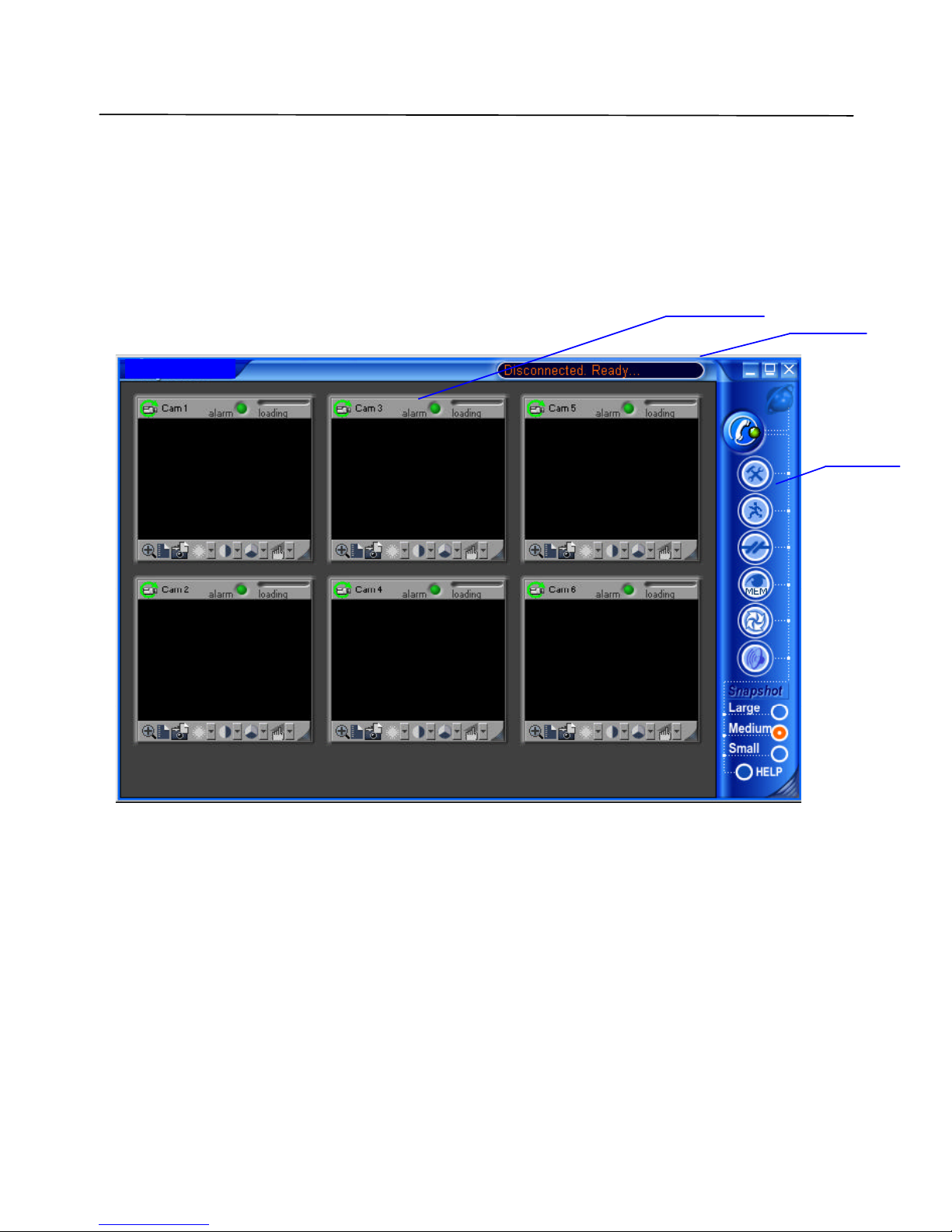
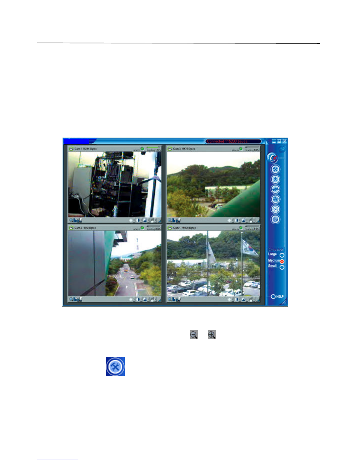
After clicking on the Lorex icon to launch the DVS client program, the main screen, in its initial
state will be shown below (Figure 3). The window consists of three main elements:
• Image windows
• Main control panel
• Status bar
Figure 3 DVS client program (initial state)
Main control panel at the right is comprised of several buttons that allow you to issue
commands to the remote DVS unit and view or modify its configuration parameters (see section
5.1.1 for detailed description of each button). The resizable Image windows are intended to
show video images acquired from the remote DVS unit. The Status bar is provided to show the
current operational status.
LOREX
Status bar
Control panel
Image window
Page 16
USING THE CLIENT SOFTWARE
Lorex Dialup Video Server User’s Guide
16
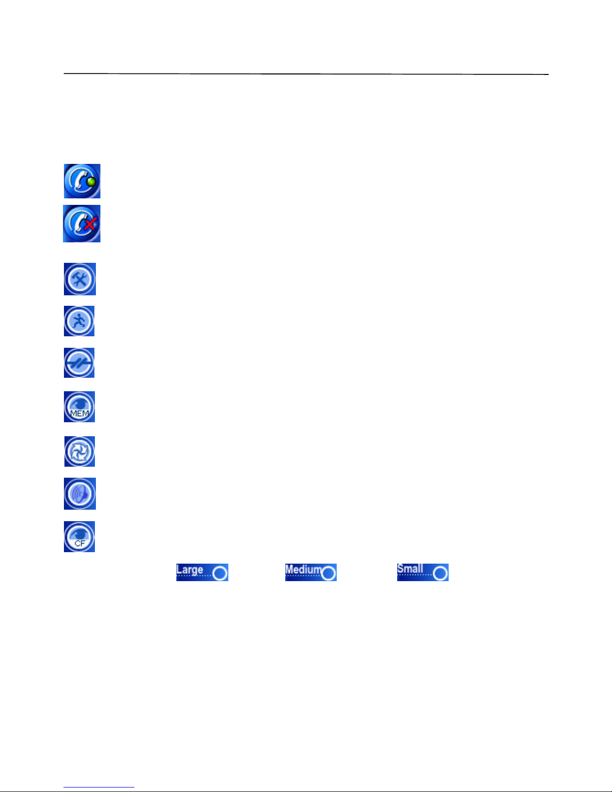
5.1.1 Main control panel
The Lorex DVS main control panel provides an easy way to perform any operation with a
remote unit. Each of the buttons are described in detail below.
Displays the Establishing connection dialog and lets you connect to any of the
available remote DVS units. Use the same button to break the connection.
When connected, the control button changes.
Properties button lets you view and modify configuration information stored in the
remote unit that you are currently connected to (refer section 5.2 for details).
Motion detection button displays motion detection control window (refer section 5.3
for details).
Sensor and relay button displays relays/sensors control window (refer section 5.4 for
details).
Image memory button activates the DVS internal image memory control window that
shows a preview of images stored on board (refer section 5.5 for details).
PTZ control button activates the PTZ control window (refer section 5.6 for details).
Audio control button activates the control window with all available audio functions
(refer section 5.7 for details).
CompactFlash memory button activates the DVS CompactFlash window that
maintains all operations with files (refer section 5.8 for details).
Snapshot size buttons: (680x480), (340x240), (170x120) affect
the resolution of images, captured into the DVS internal image memory by mouse clicking on
the image window.
Page 17
USING THE CLIENT SOFTWARE
Lorex Dialup Video Server User’s Guide
17
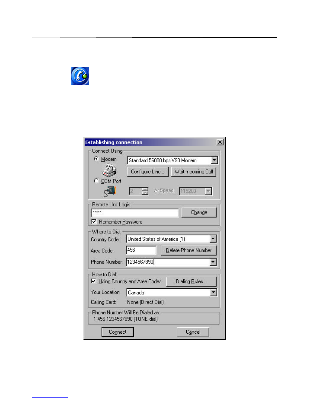
5.1.2 Getting initial images from the DVS
Before you can get any images from the DVS unit, you need to establish a connection from your
PC. Press the (Connect to remote unit) button on the main control panel. This will
bri ng up the Establishing connection dialog as shown in Figure 4. Use the Phone number
field to enter the telephone number assigned to the line connected on the remote DVS unit you
are trying to access. If the DVS unit is located in another city or country, be sure to include the
long distance or international dialing codes as well as the outside line access code, if any. The
DVS program will simplify access if you “check” the Using Country and Area Codes box
below.
Figure 4 Dialing up a remote unit
Page 18

USING THE CLIENT SOFTWARE
Lorex Dialup Video Server User’s Guide
18
Note that, as you enter any telephone number in the dialog, it will be memorized automatically,
so the next time you will not have to retype it again. Simply pull the list down by the small
arrow button on the right to choose from the 10 most recently used numbers. You can remove
unwanted telephone numbers from the list by pressing the Delete Phone Number button right
above it.
The password is required in order to prevent unauthorized access to the remote DVS unit. Enter
the correct password in the Remote Unit Login field. Note that for security reasons the entered
password will be masked by a number of asterisks (*).
Note: The default password provided from Lorex is set to qwert (in lower case). It is
highly recommended to change it as soon as possible in order to prevent
unauthorized use of the DVS unit. See section 5.10.2 for details on how to
change the password. After the password is change d, keep a record in a safe
place so you don’t forget it.
There are a few other selections and buttons available in the dialog. These are not essential to
remote connection. A detailed description of their use is found in section 5.10.1. Simply press
Connect after entering and verifying the number.
Now your modem will begin dialing the given telephone number and attempt to establish a
connection to the DVS unit on the other end of the line. It may take some time, perhaps up to a
minute, depending on the type of line and telephone number, before a reliable connection is
established. It is possible that you will have to try dialing several times if the line is busy or the
connection is slow or unreliable. To redial, press the (Disconnect) and then
(Connect to remote unit) buttons on the main control panel again.
Selecting the COM Port button in the Establishing Connection dialog (shown in Figure 4)
performs a dir ect connection through the null-modem cable. The correct port number and
desired speed settings must be established. All modem controls are unavailable in this mode,
and thus disabled. To start the connection process you need to press Connect in the same
manner as in modem mode . Additional information on this topic can be found in section 6.2 on
page 51. When using a direct cable connection, be sure that configuration switches SW on the
back panel of DVS are set as shown in Figure 34 on page 52 before the last power up on the
DVS unit.
During the connection process, its current state will be displayed in the Status bar of the main
window. Connection failure may occur if you have the wrong password, busy line, etc. This will
help you monitor the programs current state.
Page 19
USING THE CLIENT SOFTWARE
Lorex Dialup Video Server User’s Guide
19
DVS unit will automatically begin transmission of the first images using the last stored or
the factory default s ettings. Loading progress bars at the top right corner of each image
window will show a green progress indicator that will advance as the image data is being
received. For use of camera auto detection, access the Image Properties dialog as described
in section 5.2.1. The process of loading images will normally take a few seconds for fast
connections, medium image resolution and quality settings. Finally, images from all of the
connected cameras to the remote DVS unit (up to four) should appear in the program
window as shown in
Figure 5.
Figure 5 Example image received from a DVS unit
You can easily change image resolution by pressing or buttons in Image Window.
The program window displays information about connection speed in bits per second (bps) in
the window Status bar.
You can also press the (Properties) button to view or change the configuration of the
remote unit that you are connected to. The DVS configuration parameters are described in
LOREX
Page 20

USING THE CLIENT SOFTWARE
Lorex Dialup Video Server User’s Guide
20
detail, in section 5.2. Finally, you can terminate the connection by pressing the
(Disconnect) button.
Page 21

USING THE CLIENT SOFTWARE
Lorex Dialup Video Server User’s Guide
21
5.1.3 Image window description
Figure 6 shows all controls available from the image window.
Figure 6 Image window interface
Images from all cameras are updated in cyclic mode by default. You are also able to assign one
camera for faster update, by mouse clicking on the image window caption (single mode). Image
window frame will be highlighted in single mode. You may return to cyclic mode by mouse
clicking on the Image window caption, or in the main window area or by pressing Esc on the
keyboard.
Use Include in/exclude from update image cycle button to control renew image cycle in cyclic
mode. When this button is pressed, it becomes gray . This image window will be excluded
from the renew image cycle.
You are able to adjust image quality settings as you like, using Image quality slider. Minimal
quality settings allow you to receive video at a frame rate up to 6 frames per second at 31200
bps modem connection from a single camera.
To change the image window size, you should use Change window size button, and resize the
image window by dragging the resize corner of the window. When you press Change window
size button, all image windows are rearranged in the main window to fit the screen using small
(170x120) or medium (340x240) video resolutions, without stretching. Thus, all size changes
that you have made by dragging the right bottom corner of the image window and main window
will be discarded. To avoid this, you should uncheck Enable image windows auto resize
Resize corner
Save image as JPG
Image quality
Loading time (sec)
Loading progress bar
Alarm indicator
Include in/exclude from
update image cycle
Camera name
Save sequence as AVI
Change windo
w size
Image Area
Image Brightness, Contrast, and Saturation settings
Page 22

USING THE CLIENT SOFTWARE
Lorex Dialup Video Server User’s Guide
22
check box in Image properties dialog (section 5.2.1 on page 23), then manually align all
windows. Image windows can be moved within the application window, as you like.
Adjust image settings: Brightness, Contrast, and Saturation using pop up sliders. The default
values (middle values) work fine with most of color video cameras under regular day lighting
conditions. If you intend to download images taken at twilight or at night or in case of other
special circumstances, you may need to find a more suitable combination of these parameters.
To take snapshots at a high quality/resolution you need to click on a specific Image window,
and the picture will be captured to the internal DVS me mory. Refer to section 5.5 on page 33 for
detailed description of image memory management.
Use the Save image as JPG and Save sequence as AVI buttons to store image window
contents in files. The downloaded images will be saved in JPEG or AVI format into the folder
specified by the corresponding parameter in the DVS Image Properties dialog shown in Figure
7. The file name is chosen automatically, based on the date and time that the image was
acquired by the DVS unit.
Page 23

USING THE CLIENT SOFTWARE
Lorex Dialup Video Server User’s Guide
23
5.2 Configuring the remote DVS unit
The DVS configuration settings can be accessed by pressing the (Properties) button,
after the connection is established, allowing you to access the property pages. Each DVS unit
has its own individual configuration options, such as callback telephone number, time, etc.
These parameters should be viewed or modified independently if more than one DVS unit is
used. Only a small portion of configuration information is actually stored on the client PC and
can be shared between many DVS units. The configuration options are shown and described in
detail in the following subsections.
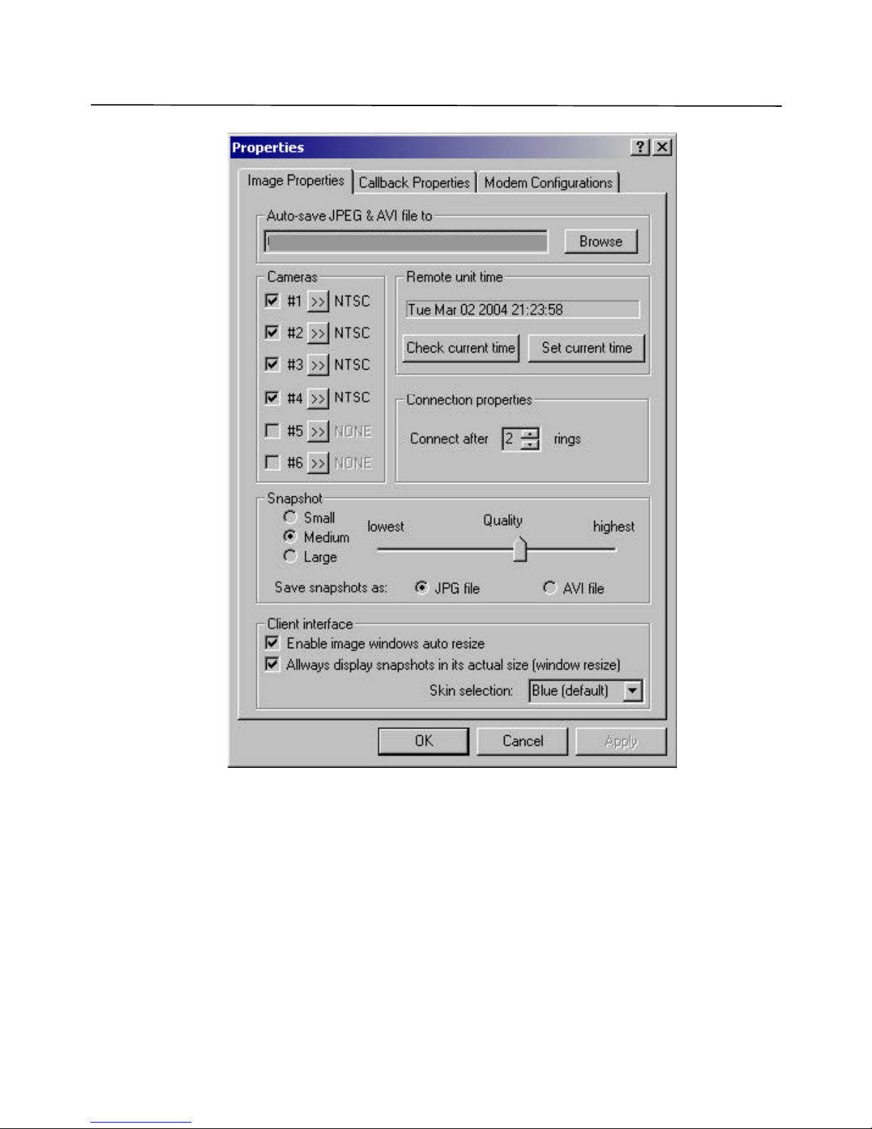
5.2.1 Modifying basic and image parameters
The first page of the DVS configuration dialog is dedicated to the Image properties. It is
shown in Figure 7.
The field Auto save JPEG & AVI file to… allows you to specify the target path (drive letter
and folder name ) intended for storing the JPEG and AVI images downloaded from one or more
DVS units. You may specify the location of the local or networked hard drive or removable
storage. Use the Browse button to select the path interactively. This parameter is stored
automatically.
After DVS has been connected, the image windows are activated based on the selection made in
the Cameras menu and all transmitted images have the exact date and time (group Remote unit
time). Check this by pressing Check current time button and synchronize it with your
computer clock by clicking the Set current time button. You can select a specific camera in
the Cameras menu that you want to monitor. By checking the Cameras, you activate an auto-
search of the selected video input.
After the DVS has been connected, the image windows get activated on the basis of the selection
made in Cameras field, given on the left of the tab. Here you may select the camera that you
want to monitor. By checking the cameras check box, you can activate the Auto Search of the
selected video input every time.
Connection properties group allows you to specify the number of rings the DVS unit will allow
before “picking up the phone” when receiving a call from PC. The default setting instructs the
DVS to answer after 2 rings. If you have a dedicated telephone line for the DVS, it may be a
good idea to decrease this parameter down to 1 to facilitate faster access time. On the other
hand, if the same line is being shared between the DVS and a voice telephone, you may want to
increase this parameter up to 9 to let somebody answer the incoming voice call before the DVS
ties up the line .
Page 24
USING THE CLIENT SOFTWARE
Lorex Dialup Video Server User’s Guide
24
Figure 7 Selecting image path, snapshot quality and other parameters
The slider for the Snapshot quality allows you to adjust the quality of images captured to
internal DVS memory by clicking on the image window . The same settings will be used for
alarm snapshots made in callback mode and CompactFlash recording. This quality factor will
not only affect the image quality appearance, but will also influence the image transmission
time and the quantity of snapshots that can be saved in internal DVS memory (this is especially
important for callback mode). For faster downloading, it is not recommended to choose high
C:\Program Files
\
Lorex
\
Dialup Video Server
Page 25

USING THE CLIENT SOFTWARE
Lorex Dialup Video Server User’s Guide
25
quality settings. The image size increases exponentially with higher quality, and can greatly
lengthen transmission.
Enable image window auto resize check box lets you disable the rearrangement of image
windows inside of a main window, so you can apply your own position and size of image
manually. These settings will be saved.
Always display snapshots in its actual size (window resize) check box lets you disable resize
and center position of snapshot windows, so one can apply your position and size of snapshot
window manually. These settings will be saved.
Skin selection drop down menu allows different graphic user interface representation.
5.2.2 Setting up Callback parameters
DVS has the ability to automatically call the client PC if motion is detected in the monitored
area, or if an alarm is set. This is known as a callback function.
DVS will access the client PC after the detection of motion or triggering signals from the alarm
sensors, after which it will start transmitting images. The phone number to be dialed and the
required actions after the motion or sensors detection are defined in the Callback Properties
dialog shown in Figure 8. You need to type in the Callback phone number (be sure that you
have selected correct Tone Dial or Pulse Dial mode), select the folder for saving images in
Save callback images to field, specify the number of sequential callback attempts (up to 5),
time interval between dialing series, and select a Sound beep, if desired, to receive sound
notification on Callback. If you wish to proceed with Callback mode after successful callback
attempt, check Auto proceed callback mode after callback event checkbox. Please refer to the
section 5.9 on page 42 for further de tails on the callback function.
Page 26

USING THE CLIENT SOFTWARE
Lorex Dialup Video Server User’s Guide
26
Figure 8 Specifying Callback mode properties
5.2.2.1 Configuring the alarm sensors
The signals from magnetic, infrared or sensors of other type, installed on the doors, windows, or
ceiling can be directly connected to DVS and used as trigger signals for alarm image capture and
callback with or without video motion detection. Clicking the Configure sensors button in the
Callback Properties dialog will display the Sensor controls and out alarms dialog shown in
Figure 9.
C:\Program Files
\
Lorex
\
Dialup Video Server
Page 27

USING THE CLIENT SOFTWARE
Lorex Dialup Video Server User’s Guide
27
There are two kinds of sensor state (see State field in Figure 9):
• Normally Open - the non-signaled state of sensor input – HI, when sensor input is not
connected or connected to digital HI level
• Normally Closed - the non-signaled state of sensor input – LO, when sensor input is tied
to the ground or digital LO level.
By pressing the Restore to default button you can assign all alarms as Normally Open. A green
sensor icon in the State field means signaled state - alarm. After deciding all sensor states, you
can press the Remember current state as normal button for saving your configuration and
now DVS will generate an alarm signal when the sensor is toggled.
Figure 9 Configuring the alarm sensors
The Enable/Disable sensors control will allow you to activate or deactivate each sensor. You
can specify the name of sensor in the edit box. The Camera for sensor field allows you to
choose the camera and assign it to a sensor alarm. One of four cameras may be connected to
each sensor. If we have a sensor set on a door, and one of the cameras is directed at the door,
you should specify the camera number in the Camera for sensor field . When this sensor
toggles to a signaled state, DVS will capture a defined number of snapshots with a defined
delay, in seconds (Num Images & Delay) from the defined camera. When 1 image from the
camera is specified, a delay will occur before the image is captured.
You may specify the time the output relays will be toggled in the Relay toggling timeout field.
The relays to be toggled are assigned in the Toggle Relays field. In the example in Figure 9, the
Page 28

USING THE CLIENT SOFTWARE
Lorex Dialup Video Server User’s Guide
28
output relays 0; 1 will be toggled for infinite and 5 seconds after, the sensor will alarm 0 and 1
respectively. You may clear all checked Toggle Relays checkboxes with the Clear button.
Page 29

USING THE CLIENT SOFTWARE
Lorex Dialup Video Server User’s Guide
29
5.2.3 Changing external modem parameters
Note: This section is applicable to the external PSTN or ISDN modem users only. Use
Direct cable connection (COM port) mode (see section 6.2) to setup this settings
before entering Custom configuration (External modem) mode (see section 6.3).
Figure 10. Setting external DVS modem parameters
In the Modem Configurations dialog (Figure 10) the user can specify the operation parameters
for the external modem and make full use of its functions. Any PSTN, ISDN modem with the
RS232 interface can be used as an external modem. In this mode the user may specify the
Page 30

USING THE CLIENT SOFTWARE
Lorex Dialup Video Server User’s Guide
30
modem initialization string that must be executed after the modem starts. There are, however, a
few limitations:
1. The length of string should be less than 40 characters.
2. All characters should be typed in the same case. (either lower case or upper case)
3. Set the modem to digital communication mode (i.e. X0, X1, X2, X3, X4).
4. Some ISDN modems cannot accept commands ending with <CR>, <LF> characters.
They may need only <LF>. This is also determined during the configuration set up.
5. You must prohibit echo (use the E0 command)
The default string is ATE0S0=2X0V0L0<CR><LF> - this is suitable for standard external
PSTN modem.
The external modem may have 9600, 19200, 38400, 57600 or 115200 baud rates for the RS232
port.
The user specified parameters are stored in the DVS unit’s internal Flash-memory, and they are
used at startup for configuration of external modem from the DVS side.
Typing different AT-commands separated with blank spaces divides single string into multiple
parts. In this case, commands will be sent to the modem, one after another, every time,
acknowledged by the modem’s OK response.
Select the proper data transfer rate between the modem de vice and the Ext (RS232) port of the
DVS. When done, press the Apply button to store the new custom initialization parameters in
the DVS unit.
Page 31

USING THE CLIENT SOFTWARE
Lorex Dialup Video Server User’s Guide
31
5.3 Motion Detection Control
The motion detection function of the DVS provides you with the ease and convenience of
automatic monitoring from a remote location. Pressing the (Motion detection) button
brings up the motion sensitivity control window shown in Figure 11. If you wish to use video
motion detection, you can set the sensitivity level using the Motion threshold slider. You can
test the sensitivity level. The Running man image will start to flash when motion is detected. It
is also possible to assign motion detection to cameras by checking Include /exclude camera in
motion detection check box.
Figure 11 Motion sensitivity control window
Note: 1. When this window is activated, images in the Image window will be updated as
an alarm event. To return back to normal image update you should deactivate this
window by pressing again or by activating another control window.
2. Sometimes one or more video inputs can be sensitive, even though there is no
visible motion in the monitoring areas. This may be due to daylight lamp usage
(not incandescent lamp) different camera types, or possibly different electrical
levels of video input signals (perhaps video cable connection quality). Try
changing the video inputs, or refrain from using certain video inputs for motion
detection purpose.
After pressing the Break connection and switch to callback mode button, the DVS will go to
Callback mode. Please refer to the section 5.9 for the details on the callback function.
Break connection and switch to callback mode
Include /exclude camera in motion detection
Current motion activity indicator
Motion threshold slider
Running man
Page 32
USING THE CLIENT SOFTWARE
Lorex Dialup Video Server User’s Guide
32
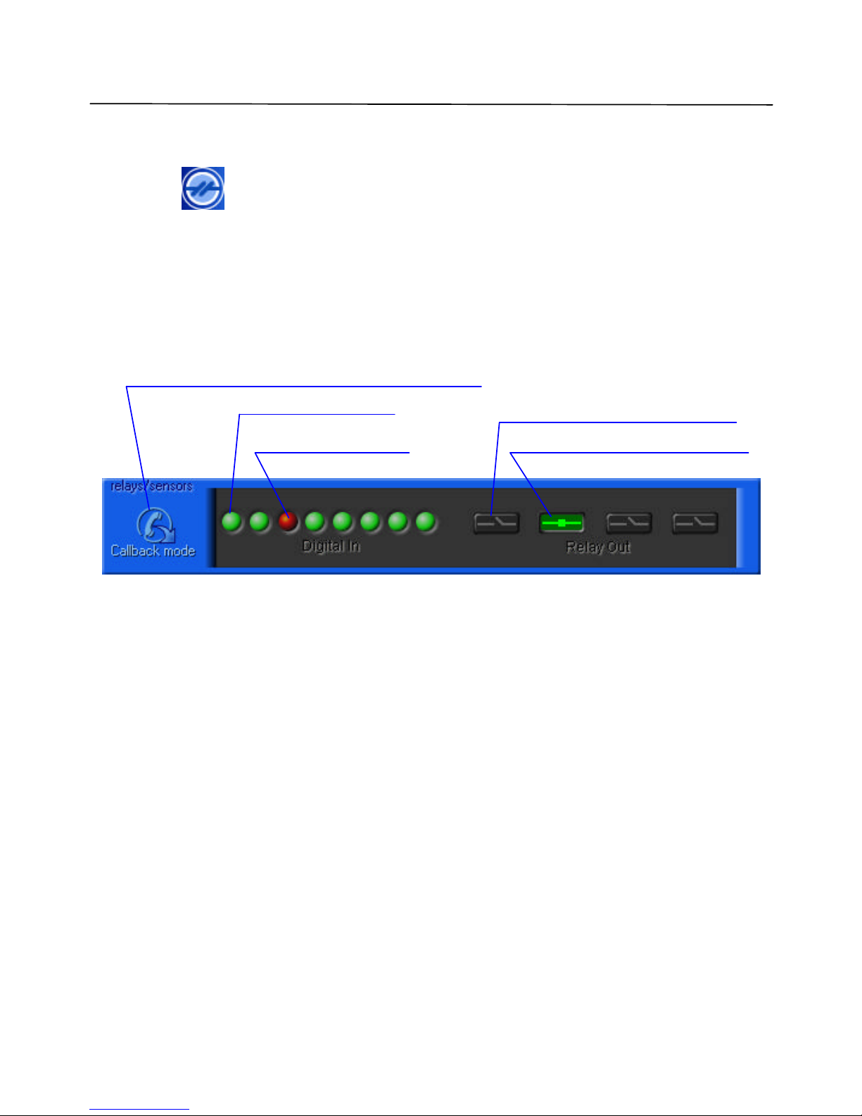
5.4 Relays and sensors control
Pressing the (Relays and sensors) button brings up the relay/sensors window shown in
Figure 12.
DVS can generate up to 4 relay output signals. You can turn relays on or off by pressing the
Relay Out buttons. Do this, set-up the initial relay states.
For sensors, a red color means an alarm state. Press any sensor button to bring up the dialog for
configuring the alarm sensors (shown in Figure 9 on page 27).
Figure 12 Relays/sensors control window
After pressing the Break connection and switch to callback mode button, the DVS will go to
Callback mode. Please refer to the section 5.9 for the details on the callback function.
Sensor 0 (
initial state)
Relay control button (ON state)
Relay control button (OFF state)
Sensor 2 (alarm state)
Break connection and s
witch to callback mode
Page 33
USING THE CLIENT SOFTWARE
Lorex Dialup Video Server User’s Guide
33
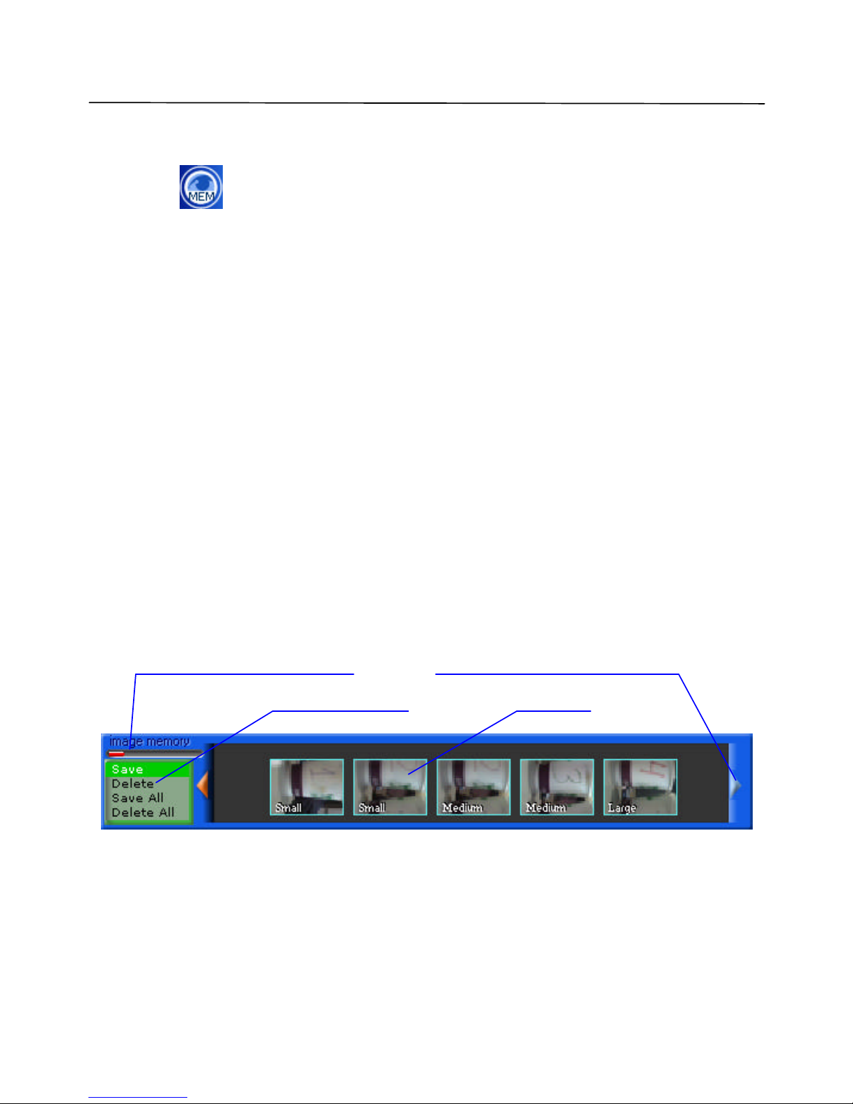
5.5 Internal image memory management
Pressing the (Image memory) button or making snapshots by mouse clicking on an
image window activates the DVS internal image memory window, shown in Figure 13.
In the upper left corner there is a Filling image memory indicator. This allows you see how
much memory you can still use for making snapshots.
Using Preview allows you to either download the images or delete them without downloading.
The default state of Save/Delete buttons are shown in Figure 13 (Save button pressed). If you
click on a specific Preview, the downloading process will be initiated (Figure 14). You will
then see a Snapshot window with a downloading progress bar. After the download is
complete, the image is saved automatically as a JPEG file with an associated date/time stamp.
You should specify a destination folder for snapshots in Image properties (see section 5.2.1).
Press the Delete button and click Preview to delete the corresponding image from memory
without downloading.
Use the Save all button to download and save all images, or Delete all to clear the whole
memory space.
You should also take into consideration that the downloading of snapshots is quite a prolonged
process.
Figure 13 Image memory control window
Filling image memory indicator
Save/delete buttons
Preview
Fi lling image memory indicator
Preview scroll control
Page 34

USING THE CLIENT SOFTWARE
Lorex Dialup Video Server User’s Guide
34
Figure 14 Downloading snapshots
Snapshot Area
Downloading progress bar
Snapshot information (size in bytes, time)
Page 35
USING THE CLIENT SOFTWARE
Lorex Dialup Video Server User’s Guide
35
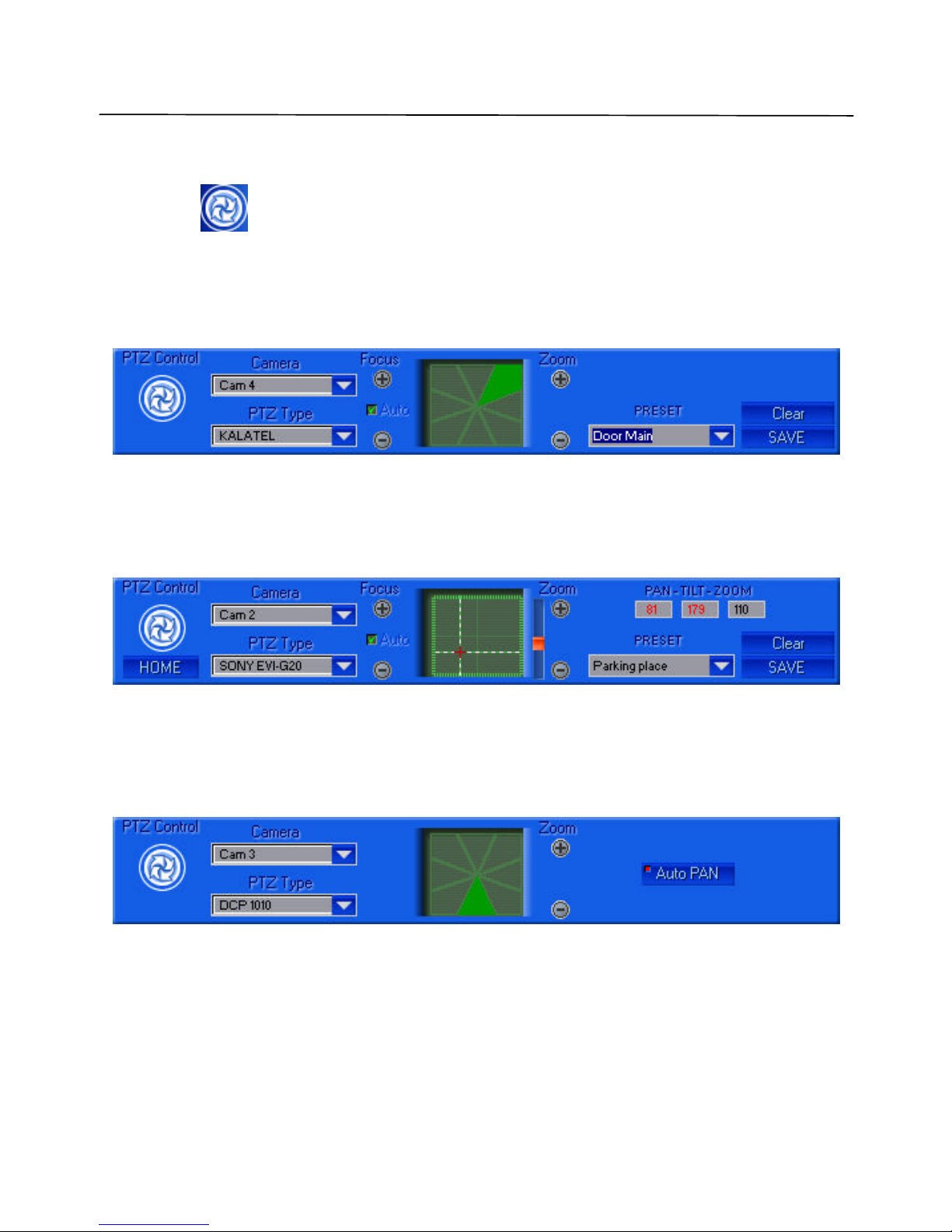
5.6 Controlling Pan, Tilt, Zoom, Focus of remote cameras
Pressing the (PTZ control) button on the main control panel brings up the PTZ
(Pan/Tilt/Zoom) window shown in Figure 15. Pressing the arrow button affects the camera
position. The Kalatel Cyber Dome camera will perform directed movement when you keep the
arrow button pressed. These positions can be saved as user defined template name. You can
adjust the camera's position while monitoring the remote location at the same time .
Figure 15 Pan, Tilt, Zoom, Focus (PTZ) window for Kalatel serial PTZ controller
If the Sony-EVI camera (EVI-G20 or EVI-D30 models) is connected through RS232, then it is
necessary to select the appropriate type from the PTZ Type drop-down menu. The dialog will
automatically change its appearance as shown in Figure 16. You can control the Sony camera by
moving the pointer in the spatial window .
Figure 16 Pan, Tilt, Zoom, Focus window for Sony EVI cameras
For DCP -1010 or other PELCO-D compatible cameras the control window will look like Figure
17.
Figure 17 Pan, Tilt, Zoom, Focus window for DCP-1010 cameras
The camera ID selection dialog (see Figure 18) appears when selecting the PTZ type. All
cameras should have a different ID for proper function. As soon as the PTZ type is assigned to
a camera number, you can easily access control from camera to camera by clicking on the
caption in the Image Window, shown in Figure 6, on page 21.
Page 36

USING THE CLIENT SOFTWARE
Lorex Dialup Video Server User’s Guide
36
Figure 18 Camera ID selection dialog
Here is a list of PTZ cameras currently supported by the DVS software:
• KALATEL (Cyber Dome) cameras
• SONY EVI G20, SONY EVI D30 cameras
• Philips TC700/TC8560 series protocol
• DCP-1010 or CNB-PTD302 camera (PELCO-D protocol)
Page 37
USING THE CLIENT SOFTWARE
Lorex Dialup Video Server User’s Guide
37
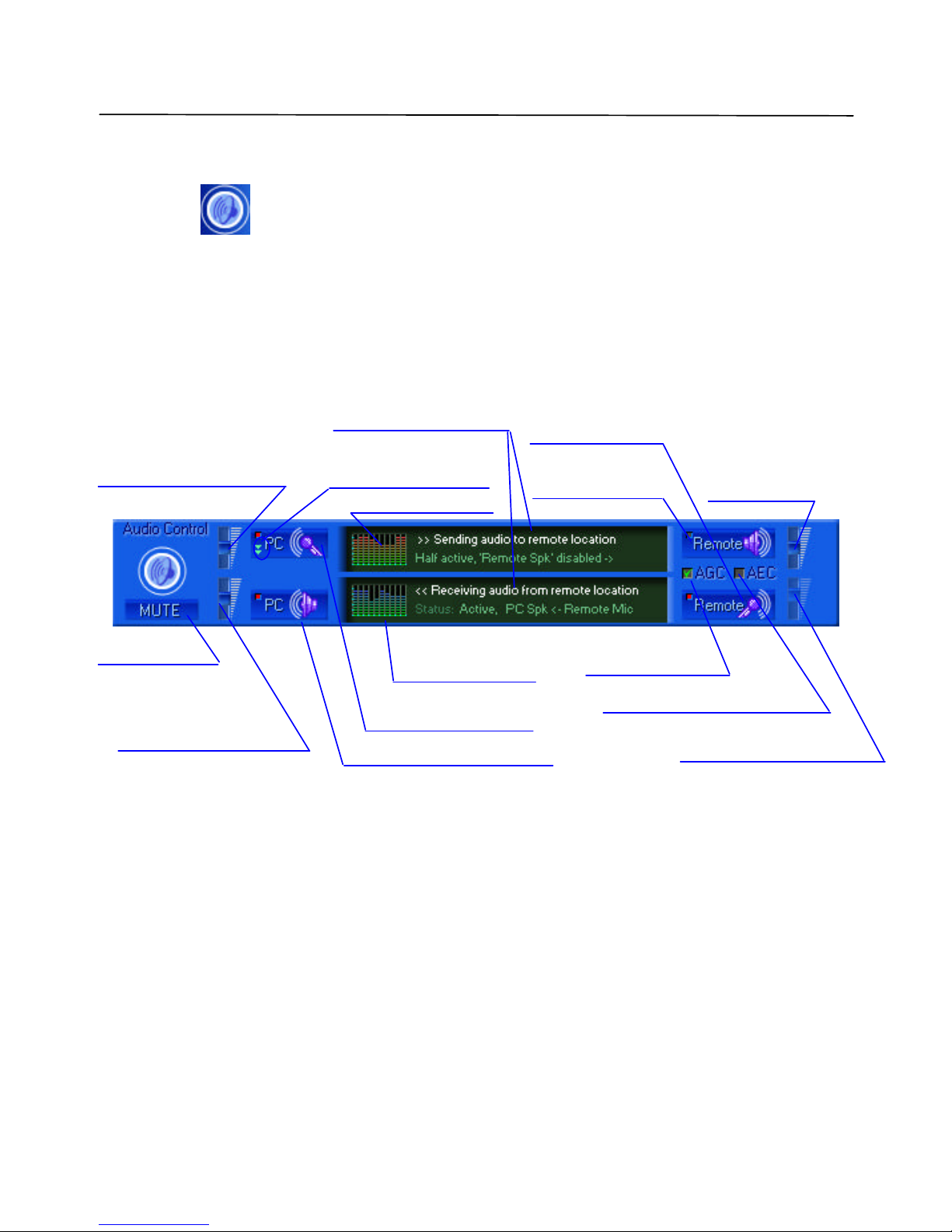
5.7 Audio stream control
Pressing the (Audio control) button on the main control panel brings up a control
window shown in Figure 19. From here you can control the incoming audio data from the DVS
and outgoing voice audio to the DVS (G723.1compressed to 5.3 K bit per sec).
A Red color square at the left top corner of each audio control button means an Enabled state.
Note: DVS MIC IN is designed for an electret-foil microphone only, (not dynamic type).
Use a microphone equipped with a stereo male jack.
Figure 19 Audio stream control window
AGC (Automatic Gain Control) – controls the DVS microphone input. When this feature is
enabled, the MIC sensitivity is changed with the current voice level in the monitoring (i.e.
hearing) area. This is extremely useful for low audio level amplification. It is strongly
recommended not to use this feature with the remote unit audio output. Use AEC to cancel the
echo from the remote speaker to the remote MIC. Since the AGC mode is incompatible with the
MIC IN volume, the slider shown is disabled in Figure 19. It is also incompatible with AEC
mode.
AEC (Acoustic Echo Cancellation) – works only when both DVS in/out audio channels are
enabled. Use this feature to avoid echo from the DVS unit’s speaker to the DVS unit’s MIC.
Volume control for PC Audio
input: LINE IN or MIC IN,
depending on PC input selected
Selection PC input type.
(LINE IN / MIC IN)
Volume control for PC
audio output (if enabled)
Toggle PC Speaker (output)
Current status information
PC encoding gain
Toggle PC MIC or
LINE IN inputs.
PC decoding gain
Mute all audio
Toggle DVS
audio output
Toggle
DVS
MIC IN
DVS
output volume
DVS MIC IN volume
Auto gain control
Acoustic Echo Cancellation
Page 38

USING THE CLIENT SOFTWARE
Lorex Dialup Video Server User’s Guide
38
When using the audio channel, take into consideration the following tips:
1. Do not set audio volume to extremely high values, it may cause voice intermodulation
(worse quality). You should start from middle sliders positions.
2. Sometimes transmitted or received audio may appear choppy. It depends on the phone
line quality or modem that you use. Try to disable the video stream by pressing
"Exclude from update cycle" button at each camera's window. (Thus you will have
audio only transmission mode).
3. Use the AGC feature if you want to hear quiet distant sounds, as soon as it amplifies the
total (background) noise level.
Page 39
USING THE CLIENT SOFTWARE
Lorex Dialup Video Server User’s Guide
39
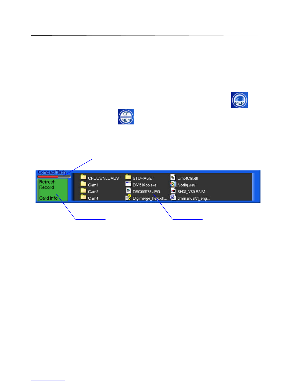
5.8 CompactFlash management
Note: CompactFlash card used with DVS should be FAT/FAT32 file system formatted.
After CompactFlash Card insertion (it can be done at any time without power off) or after
successful connection to DVS, which already has CompactFlash, Image memory button
will change its appearance lik e this: .
CF button will show CompactFlash window as in Figure 20:
Figure 20 CompactFlash window
In Files area it is possible to view files and folder contents and make simple file operations,
such as downloading, uploading and deleting files and folders. Double clicking on folder will
show the folder contents. Double clicking on file will start the downloading process. You can
make file selection by dragging mouse pointer, or by clicking on the desired files (hold shift key
pressed for multiple selection).
Card Busy/Free spa ce bar (red is busy)
Menu area Files area
Page 40
USING THE CLIENT SOFTWARE
Lorex Dialup Video Server User’s Guide
40
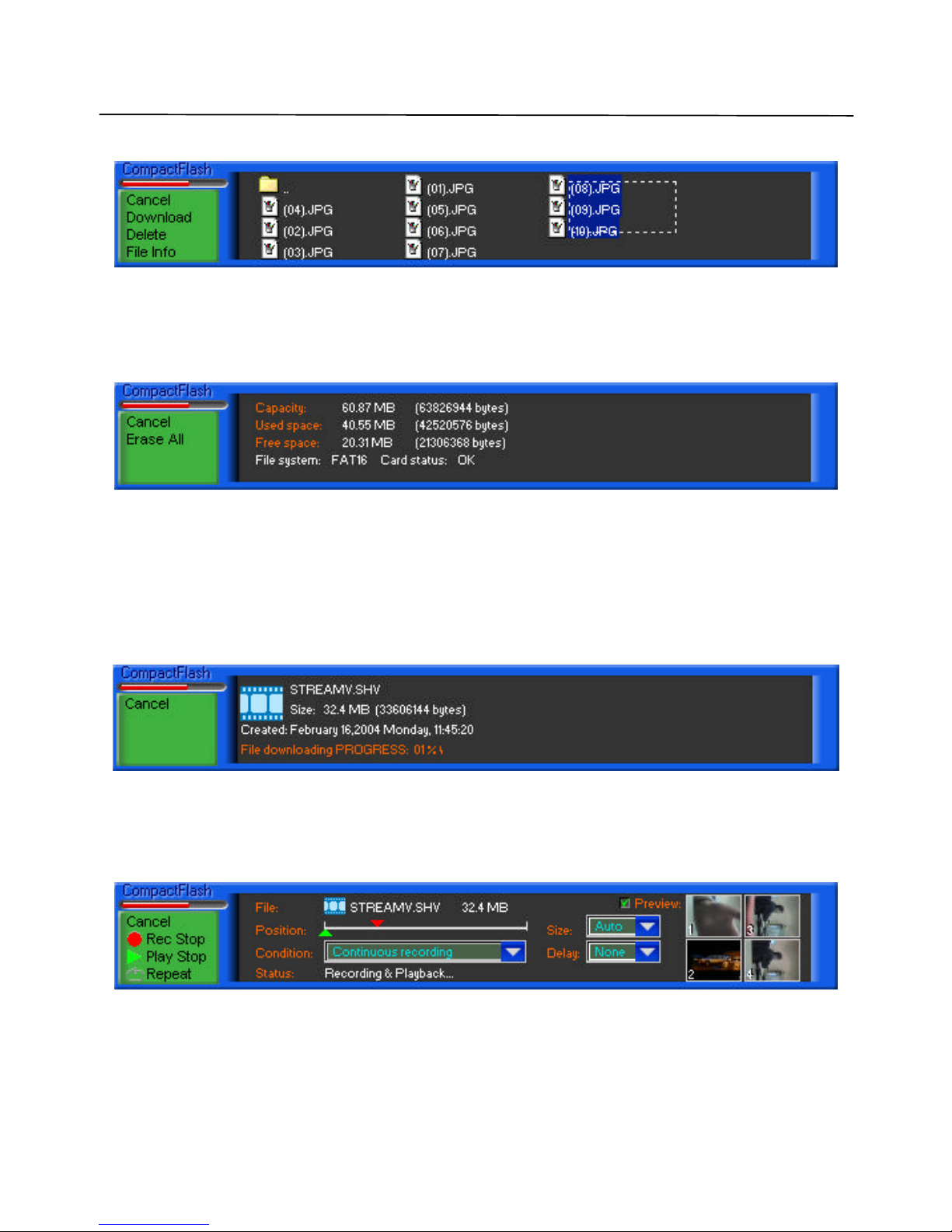
An Example of the file selection is shown in Figure 21:
Figure 21 File selection
Menu area changes when file selection occurs, offering download, delete, or view file properties
of selection. Click on cancel button (or press Esc key) to discard current selection and return to
main menu (Figure 20). Card Info main menu selection will display CompactFlash current
status as shown in Figure 22
Figure 22 Card information
Erase All menu selection initiates total card erasure. Once started, it can not be interrupted by
any user request, however it is not necessary to wait until completed, it may progress even after
disconnection.
File downloading is shown in Figure 23. Destination folders for downloaded files are in the
application folder\CFDOWNLOADS\…You are able to upload files by dragging & dropping
single or multiple selection on files. Shown in Figure 20 from any Windows explorer window.
Figure 23 File downloading
Record menu selection from main menu (shown in Figure 20) enters the recording and playback
menu. This is important when keeping a video record of events. It allows you to modify
settings, adjust file size and control record play file position. All controls are shown in Figure 24
Figure 24 Recording and Playback
Rec Start/Rec Stop and Play Start/Play Stop menu selection enables or disables recording and
playback modes. Simultaneous recording and playback are possible.
Page 41

USING THE CLIENT SOFTWARE
Lorex Dialup Video Server User’s Guide
41
Repeat selection defines whether or not file position should rewind to file beginning and
proceed record/playback from start of file after reaching the end of file. If Repeat is disabled,
then record and playback stops when file position reaches end of file.
Position in file can be adjusted independently for recording and playback. Red upper pointer is
for record file position adjustment. Green lower pointer is for playback file position adjustment.
Size of file can be Fixed (i.e. not expandable when position approaches to the end of file) and
Auto when file size is limited only by CompactFlash card’s free space. By selecting Adjust size,
it is possible to manually extend or reduce the current video stream file size.
Condition of CompactFlash recording can be:
• Continuous – unconditional, in this case, Delay defines pause between sequential frame
recording;
• Motion - by motion detection event, as defined in section 5.3 on page 31;
• Sensor - by sensor alarm as described in section 5.2.2.1 on page 26;
• Motion & Sensor;
Preview checkbox allow toggle small resolution but high frame rate playback from remote unit.
In full resolution mode you will receive recorded video in the form of snapshots (see Figure 14
on page 34).
Note: CompactFlash video recording has quality/resolution settings, which are defined by
most recently made sna pshots from corresponding cameras. (For details about
quality settings see section 5.2.1 on page 23)
All these settings are stored in file CompactFlash\STORAGE\STREAMV.INI, and vide o
recording is performed in file CompactFlash\STORAGE\STREAMV.SHV that is a registered
file type for playback with Lorex software. You can eject the CompactFlash card anytime,
connect it to PC with installed software, and view recorded video bypassing low bit rate
connection with remote DVS.
Page 42

USING THE CLIENT SOFTWARE
Lorex Dialup Video Server User’s Guide
42
5.9 Preparing and using callback mode with motion and sensors alarm
detection
The Callback mode of DVS provides you with the ease and convenience of automatic security
for a remote location. In order to activate Callback mode, first enable the Relay/sensors control
window shown in Figure 12 on page 32 or the Motion sensitivity control window shown in
Figure 11 on page 31.
Button (Break connection and switch to callback mode), by default brings up
the Callback Properties dialog shown in
Figure 25. (See also previously discussed topics in the section 5.2.2 on page 25)
Video motion detection, alarm sensor or both, can initiate Callback. You can make selection in
Alarm source selection field of this dialog.
If you want to use video motion detection for Callback, refer to section 5.3 for details on motion
sensitivity level settings and also on how to assign cameras that will participate in motion
monitoring loop.
If you want to use sensor detection for Callback, press Configure Sensors button and refer to
section 5.2.2.1 on page 26 for details on sensors settings.
Page 43

USING THE CLIENT SOFTWARE
Lorex Dialup Video Server User’s Guide
43
Figure 25 Callback properties
Displaying Callback Properties dialog allows you to check all the important settings. If OK
button is pressed, it hides the application in the Windows taskbar as shown in Figure 26.
Figure 26 DVS callback mode program icon in the taskbar.
C:\Program Files
\
Lorex
\
Dialup Video Server
Page 44

USING THE CLIENT SOFTWARE
Lorex Dialup Video Server User’s Guide
44
If Download images in background mode checkbox (see
Figure 25) is not checked, the program will be automatically re-activate, when the DVS unit
calls back. In any case, the application will download all alarm images in the background, so
you are able to use your PC without disturbance from the DVS. As soon as the DVS application
goes into callback mode, the phone connection will be terminated automatically and the modem
will be set up to answer incoming calls originated by DVS.
Once motion or sensor alarm is detected, the remote will begin to operate according to the
settings of its callback properties. It will first try to connect to the monitoring PC by calling the
phone number defined in Callback phone number field. You can select the folder for saving
images in the Save callback images to field. In the Dialing properties box, you can set the
maximum number (up to 5) of dialing tries, the interval between failed call back sequence (up to
60 minutes), and the activation of a beep sound after connection. You can also force DVS to
resume callback function after one complete callback cycle by activating the Auto proceed
callback mode after callback event check box.
The transmitted images from the callback function would be saved and named automatically.
Each file name would consist of a date and time. Each image file would have a size and quality
of the latest captured snapshot. You can see the number of images that may be captured in
callback mode by making snapshots into the internal DVS memory until it overflows.
To end the callback function, just click on taskbar icon, close snapshot window, and dial DVS
number again if you find out that DVS is currently disconnected.
Page 45

USING THE CLIENT SOFTWARE
Lorex Dialup Video Server User’s Guide
45
5.10 DVS program commands in detail
This section provide s more details about the Lorex DVS client software and allows experienced
users to take full advantage of all DVS unit’s capabilities.
5.10.1 Additional dialing options
When you connect the remote DVS unit (as shown in Figure 4), you can enter the telephone
number in one of two ways, as described below.
The first method may be more convenient if you are calling from a mobile computer (notebook)
to/from another country. The second way is somewhat simpler, when you are calling from a
stationary desktop PC to a DVS unit within the same PBX system or the same city.
Use Country and Area Code Box
You can have Windows supply the proper telephone codes by checking the Use Country and
Area Codes box. This will enable you to select the desired country (and its code) from the
Country Code drop-down list and enter the Area Code below. The system will automatically
make up and dial the correct telephone number depending on the physical location of your PC
selected in the Your Location field. You can define your current location properties by
pressing the Dialing Properties button below. This will show the standard Windows telephony
configuration dialog, similar to the one shown in Figure 27. Locations can be selected virtually
anywhere in the world that may have different phone dialing systems, outside line access codes,
etc. Consult your system administrator or Windows User’s Guide for more information on how
to change the modem dialing properties. If you want to edit or create new location, just press
New or Edit buttons respectively in the dialog shown in Figure 27 and you will be able to
configure location properties as shown in Figure 28
Exact Dial Method
The second method does not involve any special configuration, and it assumes that you know
exactly how the telephone number should be dialed. For example, if you are located inside the
office telephone switching (PBX) system and want to dial a DVS within the same building, you
may just dial the three- or four -digit extension number, such as 1234. You could type this
extension number alone (1234) and get connected without having to go through the outside
line. Alternatively, if you need to dial into a DVS unit located in another city, you would have
to dial the outside line access code, optional long distance prefix, area code and finally the
phone number with optional extension. For instance,
9W 1-213-555-1234,,,7890.
Note that the W character, above, tells the modem to wait for the second dial tone after getting an
outside line before dialing the long distance number. The triple commas (,) mean a delay for
Page 46

USING THE CLIENT SOFTWARE
Lorex Dialup Video Server User’s Guide
46
about 6 seconds before dialing the extension. Please refer to your modem manual for more on
telephone number dialing tips.
Figure 27 Specifying the location and dialing properties
Page 47

USING THE CLIENT SOFTWARE
Lorex Dialup Video Server User’s Guide
47
Figure 28 Editing location properties
The bottom group of options in the Establishing connection dialog shown in Figure 4 is called
Connect Using . It may prove helpful for those PC configurations when more than one modem
or communication device is available. In that case, you may simply select the desired device
from the drop-down list. Finally, you may configure the special device parameters, such as
connection speed, speaker volume, communication time out, etc. by pressing the Configure
Line button. A dialog similar to the example shown in Figure 29 will appear. The details and
recommendation on the proper settings depend on the device type, manufacturer and model
name. Please consult the corresponding product manual for more information.
Page 48

USING THE CLIENT SOFTWARE
Lorex Dialup Video Server User’s Guide
48
Figure 29 Configuring special modem properties
5.10.2 Changing and memorizing the DVS password
As discussed earlier, you can change the password for the DVS unit at any time by pressing the
Change button in the dialog shown in Figure 4, on page 17. This will bring up a dialog similar
to the one shown in Figure 30.
Figure 30 Changing access password for the DVS unit
Page 49

USING THE CLIENT SOFTWARE
Lorex Dialup Video Server User’s Guide
49
You will need to type in the new password twice in the two corresponding fields, and press OK.
If the old password in the Remote Unit Login field of dialog shown in Figure 4 is incorrect, or
the two copies of the new password do not match, the program will show an error message and
the connection will be terminated. If the security checks pass successfully, the new password
will become effective immediately, and you will have access to the DVS functions.
Also, you may want to have the DVS client software remember the most recently used password
by checking the Remember password box in dialog shown in Figure 4, on page 17. However,
the use of this option lowers security level since the password does not actually need to be
entered. Finally, even in the most trusted environment, it is possible for users to forget their
password.
Page 50

USING THE CLIENT SOFTWARE
Lorex Dialup Video Server User’s Guide
50
5.10.3 Retrieving software and firmware versions
You can check the software version by clicking on the icon in the upper right corner
of the Lorex DVS program. An example of the version window is shown in
Figure 31.
Figure 31 Version information
LOREX
www.strategicvista.com
Copyright® 2003 Strategic Vista
Tech. All rights reserved
Page 51
DVS OPERATION MODES
Lorex Dialup Video Server User’s Guide
51
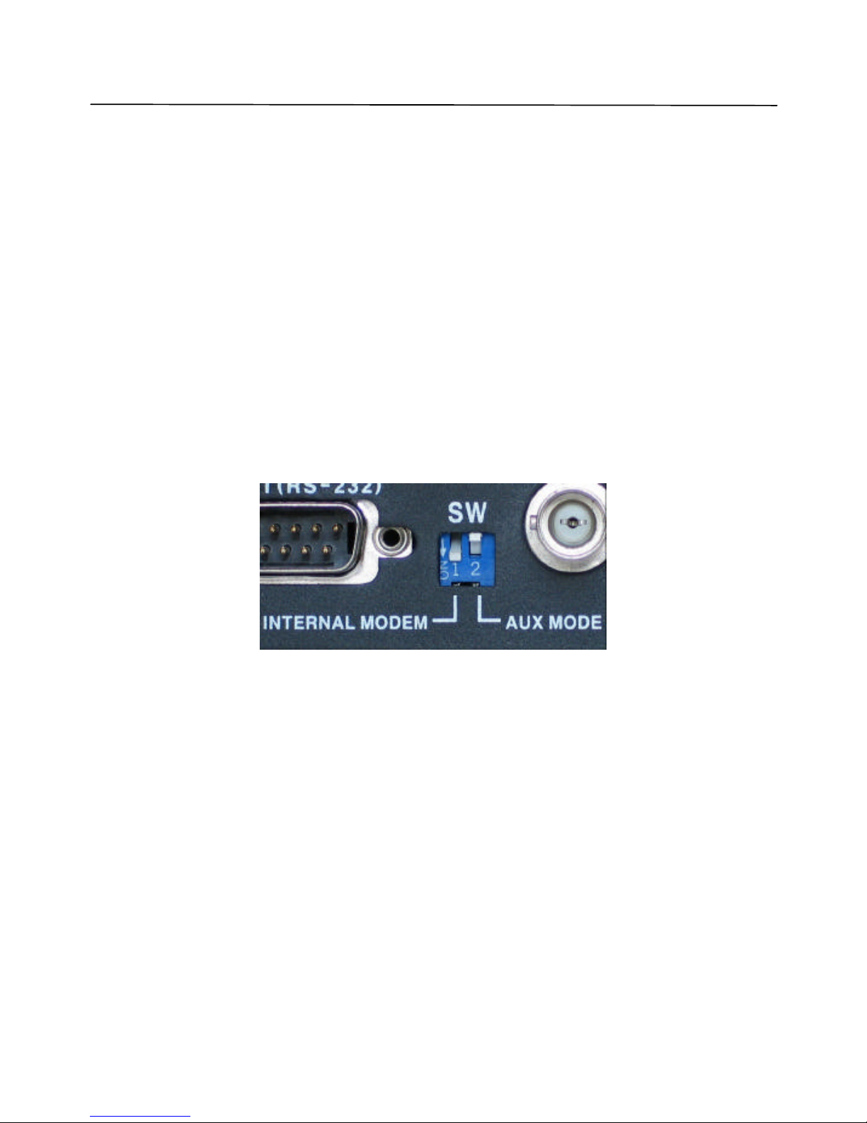
6. DVS OPERATION MODES
The DVS unit supports several modes that can be selected by the user. The mode type is
determined during the DVS startup depending on the DIP switches SW (found on the back panel
of the DVS unit).
Note: Disconnect DVS from the power supply before operation mode modification.
6.1 Internal modem mode
This mode only needs the presence of the Cermetek or FM-56WB-TP internal modem. The data
between the modem and the internal DVS bus is sent at a rate of 57600 baud. The modem then
transmits it over the analog phone lines depending on line quality and other party capabilities
with speed of up to 57600 baud.
The DIP switch configuration used during power up is shown in Figure 32
Figure 32 Switches configuration in internal modem mode
6.2 Direct cable connection (COM port) mode
The DVS unit can be connected directly to the client PC using the serial interface (RS232) port
for use with standard applications or for use by special applications such as WebDVS. The
direct cable connection allows users to achieve the fastest possible image transfer speed of
115200 bits/sec, which is over 3x faster than the maximum possible speed achieved with an
internal modem. However, the direct serial connection cannot be used if the distance between
the host PC and the DVS unit is more than 30 me ters (98 feet). Use special RS232 to
RS422/485 converters to extend the direct connection distance.
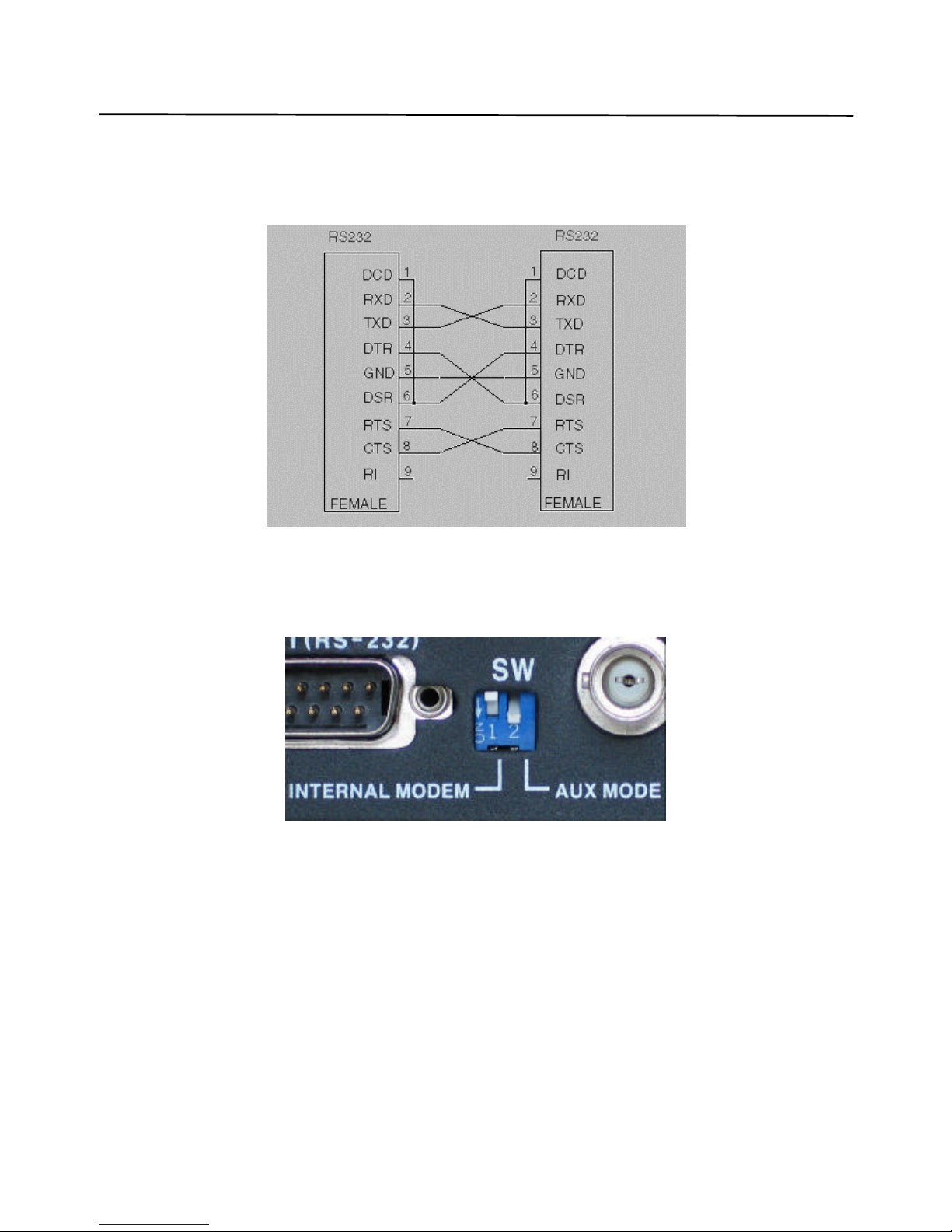
The direct connection is done by connecting any available COM port on the PC side to the Ext
(RS232) port on the DVS with a special serial cable. Another option is a connection using RxD,
Page 52
DVS OPERATION MODES
Lorex Dialup Video Server User’s Guide
52
TxD, and GND signals only. The cable should have a 9-pin female connector on each end and a
pin connection as shown on the diagram in Figure 33. The cable is supplied with every DVS
unit.
Figure 33 DVS RS-232 cable pin layout
The DIP switch configuration used during power up is shown in Figure 34
Figure 34 Switches configuration in COM -port mode
As soon as the DVS firmware starts up, its Ext (RS232) serial port will be set to the following
default mode: 9600 baud, 8 data bits, no parity, 1 stop bit.
In order to operate the DVS unit via direct cable connection, select the COM port in the
Establishing connection dialog (see Figure 4). Choose the proper COM port and desirable
connection rate (115200 is recommended). The appearance and functions of the DVS
application with direct cable connection are very similar to those using standard modems. The
only significant difference is that you do not need to dial any telephone numbers since there is
direct connection to your PC. Also, since the direct cable connection is much faster than that of
Page 53
DVS OPERATION MODES
Lorex Dialup Video Server User’s Guide
53
a modem, the “call” to the DVS is performed almost instantly by pressing the Connect button in
the Establishing connection dialog.
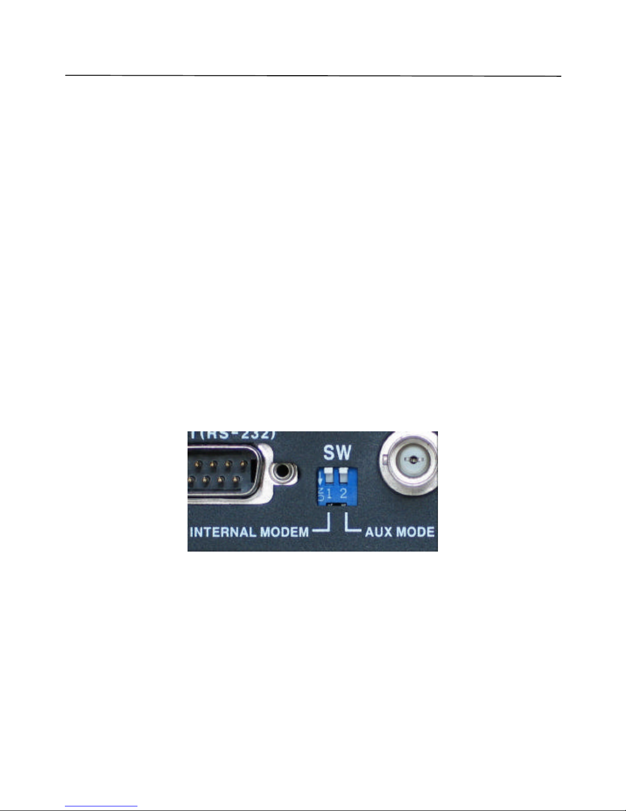
6.3 Custom configuration (External modem) mode
The Custom configuration mode allows the user to specify the operation parameters for external
communication device (modem) in order to take full advantage of its capabilities. Any analog
(PSTN) or ISDN modem or a cellular phone with the RS232 serial interface and Hayescompatible command set can be used as an external communication option for DVS. Check the
user’s manual that comes with your device and contact the nearest Lorex Technologies dealer if
you are not sure.
In custom configuration mode, the user should specify the communication device (modem)
initialization string that will be executed immediately after the DVS unit is powered up. This is
done by connecting the DVS unit directly to the PC first, as described in section 6.2, on page 51.
The exact appearance of the initializa tion string may be different from one device to another and
is usually suggested by the device manufacturer.
For recommendations concerning initialization string composition refer to section 5.2.3, on page
29.
The DIP switch configuration used during power up is shown in Figure 35
Figure 35 Switches configuration in Custom configuration mode
Page 54

TROUBLESHOOTING
Lorex Dialup Video Server User’s Guide
54
7. TROUBLESHOOTING
The DVS unit and software is designed to be very reliable and stable and should rarely cause
any problems during setup or operation.
7.1 How to get software updates and technical support
The addresses are as follows:
Strategic Vista Technologies Inc.
Head Office
300 Alden Road, Markham, ON, Canada, L3R 4C1
Toll Free Telephone: 1-888-425-6739
Facsimile: 1-905-947-0138
Please note that technical support staff will be able to help you more efficiently if you include
the following information when posting your question:
• Basic computer configuration (CPU model and clock speed, amount of the physical RAM,
modem type, any unusual configuration options)
• Type of DVS unit purchased, as well as the description of any external communication or
PTZ controller devices connected to it
• Version of the Lorex DVS client software and the detailed settings, which led to the problem
• Windows OS type and version
• All other details as necessary
Lorex Technologies Inc. technical support team will provide you with the best quality timely
assistance in order to make you completely satisfied with DVS.
Page 55

Lorex Dialup Video Server User’s Guide
55
8. Limited Warranty
1. LOREX PRODUCT LIMITED WARRANTY
LOREX warrants, to the original retail purchaser only (the “Purchaser”), that this item (the “Product”) is free
from manufacturing defects in material and workmanship, provided the Product is used in normal conditions
and is installed and used in strict accordance with the instructions contained in the Product’s Owner’s Manual.
This warranty shall be for the following warranty periods (the “Warranty Period”), commencing on the date the
Purchaser buys the Product at retail in an unused condition.
Parts and Labor: 1 year (Warranted parts do not include Bulbs, LED’s and Batteries)
LOREX’s obligations under this warranty shall be limited to the repair or replacement of any warranted parts
found by LOREX to be defective in the Product, or, in LOREX sole discretion, the replacement of the Product
found be LOREX to be defective.
Any replacement parts furnished be LOREX in connection with this warranty shall be warranted to the
Purchaser for a period equal to the unexpired portion of Warranty Period for the Product.
1.1 Warranty Exclusions
This warranty does not apply to Bulbs, LED’s and Batteries supplied with or forming part of the product.
This warranty is invalidated if other than LOREX accessories are or have been used in or in connection with
the Product or in any modification or repair is made to the Product be other than a service depot authorized by
LOREX.
This warranty does not apply to defects or damages arising by use of the Product in other than normal
(including normal atmospheric, moisture and humidity conditions) or by installation or use of the Product other
than in strict accordance with the instructions contained in the Product’s owners Manual.
This warranty does not apply to defects in or damages to the Product caused by (i) negligent use of the
Product, (ii) misuse or abuse of the Product, (iii) electrical short circuits or transients, (iv) Purchaser
adjustments that are not covered in the Owner’s Manual, (v) use of replacement parts not supplied by LOREX
(vi) improper Product maintenance, or (viii) accident, fire, flood or other Acts of God.
LOREX reserves the right to make change in design or to make additions to or improvements in its products
without incurring any obligation to modify any product which has already been manufactured.
This warranty is in lieu of other warranties, express or implied, and LOREX neither assumes nor authorizes
any person to assume for it any other obligation or liability in correction with the sale or service of the Product.
In no event shall LOREX be liable for any special or consequential damages arising from the use of the
Product or arising from the malfunctioning or non-functioning of the Product, or for any delay in the
performance of this warranty due to any cause beyond its control.
This warranty shall not apply to the appearance or accessory items including, but not limited to cabinets,
cabinets parts, knobs etc., and the uncrating, setup, installation or the removal and reinstallation of products
after repair.
LOREX does not make any claims or warranties of any kind whatsoever regarding the Product’s potential, ability or
effectiveness to prevent minimize, or in any way affect personal or property damage or injury. LOR
EX is not responsible
for any personal damage, loss or theft related to the Product or to its use for any harm, whether physical or mental related
thereto. Any and all claims or statements, whether written or verbal, by salespeople, retailers, dealers or d
istributors to the
contrary are not authorized by LOREX, and do not affect this provision of this warranty.
The purchaser may have other rights under state, provincial, or federal laws and where the whole or part of any item of
this warranty is prohibited
by such laws, it shall be deemed null and void, but the remainder of the warranty shall remain
in effect.
Obtaining Service
Should the Product require service under this warranty, the Purchaser must provide LOREX with a copy of his/ her original, dated bi
ll
of sale, receipt or invoice, failing which LOREX will not perform any of its obligations under this warranty. To claim on this warranty,
proceed with the following steps.
1 Pack the Product in a well-padded sturdy carton.
2. i). If the unit was purchased in the United States proceed as follows:
a.
Include $US 12.00 for monitors and VCR’s and $8.00 for Cameras for postage and handling (send check or money order, no
cash please), along with a copy of your dated bill of sale, receipt, or invoice, plus
a description of the Product’s apparent
malfunction and the telephone number where you can be reached during the day.
b. Return the unit to: Strategic Vista USA Inc.
C/O The Advantage Center
1955 Wehrle Drive
Williamsville NY 14221
ii). If the unit was purchased in Canada proceed as follows:
a.
Include CDN $18.00 for monitors and VCR’s and $12.00 for Cameras for postage and handling (send cheque or money
order, no cash please), along with a copy of your dated bill of sale, receipt, or invoice, plus a
description of the Product’s
apparent malfunction and the telephone number where you can be reached during the day.
b. Return the unit to: Strategic Vista Corp.
300 Alden Road, Markham, Ont. L3R 4C1
www.strategicvista.com
Always use discretion when installing video and/or audio surveillance equipment especially when there is
perceived privacy. Inquire regarding federal, state and/or local regulations applicable to the lawful
installation of video and or audio recording or surveillance. Party consent may be required.
 Loading...