

Page 1

IP Video Router and TLR-DVR
Controller (Video Web Server)
L4202
FOR MORE INFORMATION
WWW.STRATEGICVISTA.COM
BEFORE OPERATING THIS SYSTEM, PLEASE READ THIS MANUAL THOROUGHLY
AND RETAIN IT FOR FUTURE REFERENCE
Page 2
Thank you for purchasing the Lorex® IP Video Router and TLR-DVR Controller. This is
an internet based digital video server capable of connecting up to 2 channels of video
sources to distribute their compressed live video into Intranet-Internet through Ethernet
connection. It also enables DVR series products and cameras to connect to the internet
for remote monitoring or remote control.
This is a self -contained Web Server so users can access the camera server by
browsing the website over the internet using a standard browser,such as Explorer or
Netscape, and do all the management, configuration and monitoring easily.
The system contains an image compression chipset that is capable of delivering
standard JPEG and real-time video into a limited network bandwidth.
To learn more about this system or to find out more about our products available,
please visit our website at:
www.strategicvista.com
CAUTION
!
RISK OF ELECTRIC SHOCK. DO NOT OPEN.
CAUTION! TO REDUCE THE RISK OF ELECTRIC SHOCK, DO NOT REMOVE
COVER (OR BACK). NO USER-SERVICEABLE PARTS INSIDE.
REFER SERVICING TO QUALIFIED SERVICE PERSONNEL.
Explanation of two Symbols
The lightning flash with arrowhead symbol, within an equilateral
triangle, is intended to alert the user to the presence of un-insulated
"dangerous voltage" within the product's enclosure that may be of
sufficient magnitude to constitute a risk of electric shock to persons.
The exclamation point within an equilateraltriangle is intended to
alert the user to the presence of important operating and maintenance
!
THE GRAPHIC SYMBOLS WITH SUPPLEMENTAL MARKING ARE ON
THE BOTTOM OF THE SYSTEM.
“WARNING – TO PREVENT FIRE OR SHOCK HAZARD, DO NOT EXPOSE
THE UNIT TO RAIN OR MOISTURE”
(servicing) instructions in the literature accompanying the appliance.
-i-
Page 3

NOTE
This equipment has been certified and found to comply with the limits regulated by
FCC, EMC and LVD. Therefore, it is designed to provide reasonable protection
against interference and will not cause interference with other appliance usage.
However, it is imperative that user follows this manual's guidelines to avoid improper
usage which may result in damage to the unit, electrical shock and fire hazard or
injury.
In order to improve the feature functions and quality of this pr oduct, the specifications
are subject to change without notice from time to time.
FCC CLASS B NOTICE
Note:
This equipment has been tested and found to comply with the limits For a Class B
digital device, pursuant to Part 15 of the FCC Rules. These limits are designed to
provide reasonable protection against harmful interference in a residential
installation. This equipment generates, uses and can radiate radio frequency energy
and, if not installed and used in accordance with the instruction, may cause harmful
interference to radio communications. However, there is no guarantee that
interference will not occur in a particular installation. If this equipment does cause
harmful interference to radio or television reception, (which can be determined by
turning the equipment off and on), the user is encouraged to try to correct the
interference by one or more of the following measures:
• Increase the separation between the equipment and the camera and/or monitor.
• Connect the equipment into an outlet on a circuit different from that to which the
monitor/DVR or cameras are connected.
• Consult the dealer or an experienced radio or television technician for help.
STRATEGIC VISTA CORP.
www.strategicvista.com
-ii-
Page 4

CONTENTS:
GENERAL PRECAUTIONS --------------------------------------------------------------------------------------FEATURES ------------------------------------------------------------------------------------------------------- ----
PACKAGE CONTENTS -------------------------------------------------------------------------------------------
Getting StartedGetting Started
IP ADDRESS --------------------------------------------------------------------------------------------------------REAR PANEL ---------------------------------------------------------------- ----------------------------------------BOTTOM PANEL----------------------------------------------------------------------------------------------------HARDWARE CONNECTION AT SERVER SITE-------------------------------------------------------------
Static IP SettingStatic IP Setting
SOFTWARE INSTALLATION------------------------------------------------------------------------------------IP SETTING-----------------------------------------------------------------------------------------------------------Video Web Server SETTING---------------------------------------------------------------- ---------------------DVR REMOTE SETTING ------------------------------------------------------------------------------------------PIN CONFIGURATION ---------------------------------------------------------------------------------------------CONNECTING TO A PC VIA THE INTERNET ----------------------------------------------------------------
Dynamic IP Setting Dynamic IP Setting
WHAT IS A DYNAMIC IP ADDRESS---------------------------------------------------------------------------SOFTWARE INSTALLATION------------------------------------------------------------------------------------SYSTEM RESET-----------------------------------------------------------------------------------------------------DDNS REGISTRATION FOR A DYNAMIC IP ADDRESS-------------------------------------------------CONNECTING THE PC TO A ROUTER / ROUTER LOGIN----------------------------------------------ROUTER SETTING-------------------------------------------------------------------------------------------------IP SETTING-----------------------------------------------------------------------------------------------------------VIDEO WEB SERVER SETTING--------------------------------------------------------------------------------DVR REMOTE SETTING ------------------------------------------------------------------------------------------PIN CONFIGURATION ---------------------------------------------------------------------------------------------CONNECT ALL DEVICES -----------------------------------------------------------------------------------------CONNECTING TO A PC VIA THE INTERNET---------------------------------------------------------------
1
2
3
3
4
4
5
6
8
9
11
12
13
14
14
14
14
16
19
21
22
24
24
25
25
Operation GuideOperation Guide
SOFTWARE OPERATION AT THE REMOTE SITE -------------------------------------------------------CONTROL PANEL & BASIC OPERATION ------------------------------------------------------------------PLAYBACK OPERATION ---------------------------------------------------------------------------------------ADVANCED SETTING --------------------------------------------------------------------------------------------
FAQ’S ------------------------------------------------------------------------------------------------------------------SPECIFICATIONS ---------------------------------------------------------------- -----------------------------------APPENDIX#1 DVR CONTROL ---------------------------------------------------------------- ------------------APPENDIX#2 SENDING E-MAIL --------------------------------------------------------------------------------APPENDIX#3 SOFTWARE DOWNLOAD ----------------------------------------------------------------------
REFERENCE NOTES -----------------------------------------------------------------------------------------------CARE & MAINTENANCE -------------------------------------------------------------------------------------------
-iii-
26
27
28
29
32
33
34
36
37
38
39
Page 5

GENERAL PRECAUTIONS:
1. Read Instructions
All of the safety and operating instructions should
be read and understood before the product is used.
2. Retain Instructions
The safety and operating instructions should be
retained for future reference.
3. Heed Warnings
All warnings on the product and the instruction
manual should be followed.
4. Follow Instructions
All operating and use instructions should be followed
for optimal performance
5. Cleaning
Disconnect this video product from the power supply
before cleaning. Do not use liquid cleaners or aerosol
cleaners. Use a damp cloth for cleaning.
6. Attachments
Do not use attachments not recommended by the
video product manufacturer as they may cause
hazards.
7. Water and Moisture
Do not use this product near water - for example,
near a bathtub, wash bowl, kitchen sink, wet
basement, or near a swimming pool.
8. Accessories
Use this product only with a stand, tripod, bracket or
table recommended by the manufacturer or sold
with the product. Any mounting of the product
should follow the manufacturer’s instructions.
9. Ventilation
This product should never be placed near or over a
radiator or heat register. This product should not be
placed in a built -in installation, such as a book case
or rack, unless proper ventilation is provided or the
Manufacturer’s instructions have been adhered to.
10. Power Source
This product should be operated from the type of
Power source indicated by the marking label. If you
are not sure of the type of power supply to your
location, consult your product dealer or your local
Power company
11. Power Cord Protection
Power supply cords should not be routed so that
they are likely to be walked on or pinched by items
placed on or near them
12. Lightning
For added protection, unplug this product from its
outlet during a lightning storm. This will prevent
damage to the video product due to lightning and
power surges
13. Overloading
To avoid the risk of fire and electric shock, do not
plug this product into an over-loaded power supply.
14. Object and Liquid Entry
Never push objects into the openings of this product
as they may touch dangerous voltage points that
may result in fire or electric shock. Never spill
liquid of any kind on this product.
15. Servicing
Do not attempt to service this product yourself as
opening or removing covers may expose you to
voltage or other hazards. Refer all servicing to
qualified service personnel
16. Damage Requiring Service
Disconnect this product from the power supply
and refer servicing to qualified service
personnel under the following conditions:
a. When the power supply cord or plug is damaged
b. If objects have fallen into the product
c. If the product has been exposed to rain or liquids
d. If the product does not operate normally by
following the instruction manual. Adjust only
the controls that are covered in the instruction
manual as an improper adjustment may result
in damage and will often require extensive work
by a qualified service technician to restore
the product to its normal operation
e. If the product has been dropped or the cabinet
has been damaged
f. When the product displays a distinct change in
performance - this indicates a need for service
17. Replacement Parts
When replacement parts are required, be sure the
technician uses replacement parts specified by
the manufacturer. Unauthorized substitutions may
result in fire, electric shock, or other hazards.
18. Safety Check
Upon completion of any service to this product
ask the service technician to perform safety
checks to determine that the product is in
proper working condition.
19. Grounding or Polarization
This product is equipped with a three-wire
grounding-type plug, a plug having a third
(grounding) pin and will only fit into a
grounding-type power outlet. This is a safety
feature. If you are unable to insert the plug
into the outlet, contact your electrician to
replace your obsolete outlet. Do not defeat the
safety purpose of the grounding-type plug.
20. Power Lines
An outside antenna system should not be
located in the vicinity of overhead power lines
or other electric light or power circuits, or where
it can fall into such power lines or circuits.
When installing an outside antenna system,
extreme care should be taken to keep from
touching such power lines or circuits as contact
with them might be fatal.
21. Wall or Ceiling Mounting
The product should be mounted to a wall or ceiling
only as recommended by the manufacturer.
22. Heat
The product should be situated away from heat
such as radiators, heat registers, stoves, or other
products (including amplifiers) that produce heat.
-1-
Page 6

CAUTIONS:
1. All the warnings and instructions of this manual should be followed
2. Remove the plug from the outlet before cleaning. Do not use liquid aerosol detergents. Use
water damped cloth for cleaning
3. Do not use this unit in very humid and wet places
4. Keep enough space around the unit for ventilation. Slots and openings of the cabinet should
not be blocked.
5. During flashes of lightning or cracks of thunder, or when the system is not used for a long time,
unplug the system power supply and disconnect the cables to protect the unit from lightening
or power surges.
Features
• Compatible with most CCTV Products.
• Empowers all video output devices watching and controlling on the Internet or LAN.
• Auto Network Reconnection (ANR).
• Support alarm triggers recording & watch dog function.
• Support Dynamic IP address via a Router.
• Support 4 alarm inputs.
• Duplex function, record and playback simultaneously at client site.
• Auto e-mail warning system & images uploading function (to FTP site) th at will remind you
if an external alarm was triggered.
• Intelligent non-stoppable recording function after ANR.
• Support Multi AP screens and HTTP display (IE browser).
• Unique video player.
-2-
Page 7
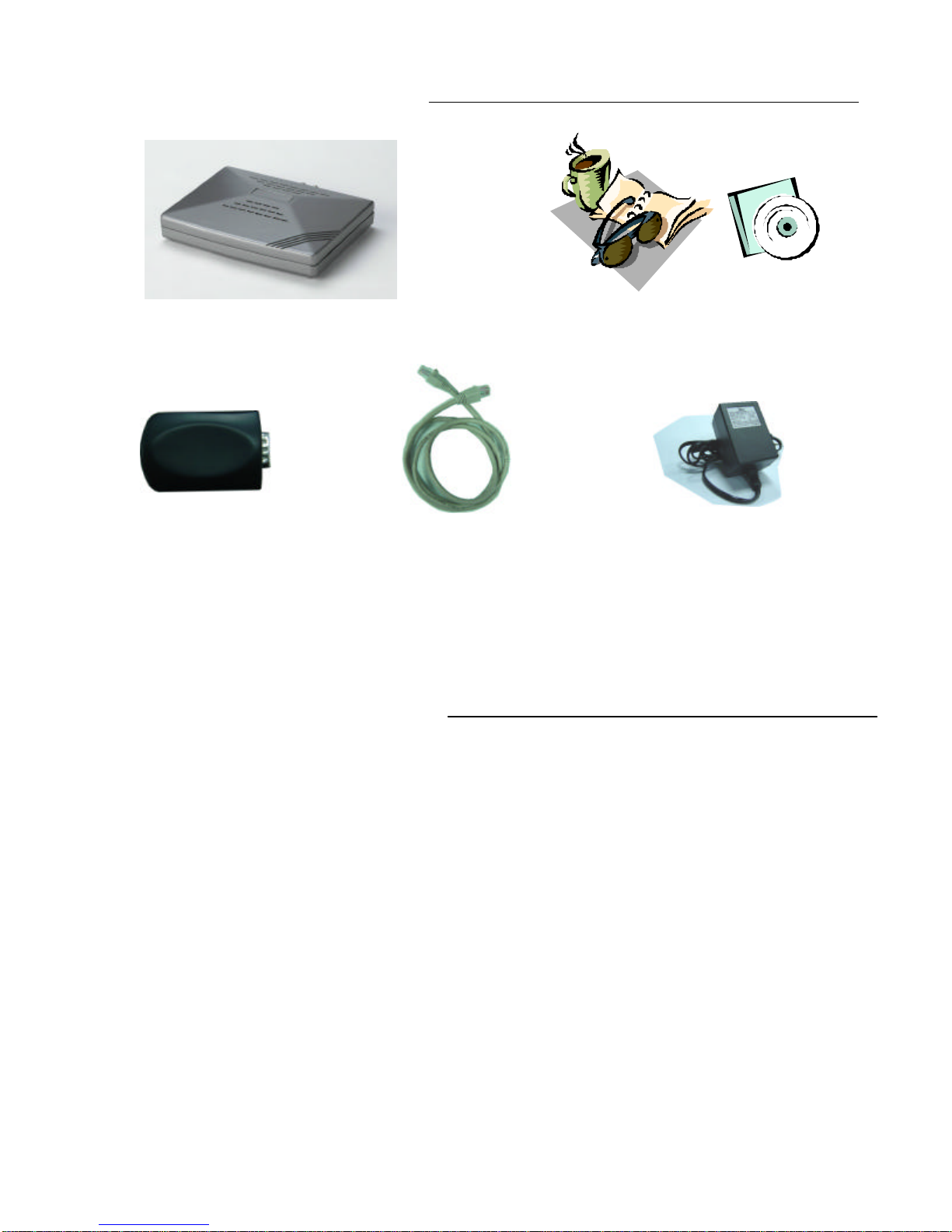
PACKAGE CONTENTS:
IP Video Router & TLR-DVR Controller Owner’s Manual & CD
Terminal block Crossover LAN cable
CHECK YOUR PACKAGE TO MAKE SURE THAT YOU RECEIVED THE COMPLETE
SYSTEM, INCLUDING THE COMPONENTS SHOWN ABOVE.
Power Adapter & Cord
GETTING STARTED:
Before installation, contact your ISP (Internet Service Provider)
for your own IP address.
Note : The bundled software is compatible with the following Windows operating
systems : WIN2000, WIN2003 and WINXP. It is not recommended to use with WIN98
& WIN ME, which may cause system conflictions with the software.
-3-
Page 8
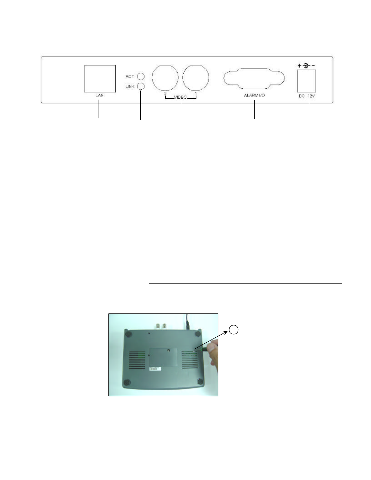
CONTROL - REAR PANEL:
1 2 3 4 5
1. LAN
Connect the RJ45 Crossover LAN cable to the internet, or dir ectly to a PC
2. ACT & LINK LED’s
When these LED’s are blinking it indicates that the network is in operation
3. VIDEO INPUT (BNC, 2 channels)
Connect to a video source, such as a camera or DVR video output.
4. ALARM I/O (optional for advanced applications)
Connect control devices, such as a PTZ Camera, DVR, Motion Sensors, external
alarm signal inputs, etc
5. POWER
Plug in the supplied power adaptor (12V / 500mA).
BOTTOM PANEL :
Bottom
3
RESET BUTTON (at the bottom of the Video Web Server)
Push this button for more than 5 seconds to reset the settin g back to the default
setting.
-4-
Page 9
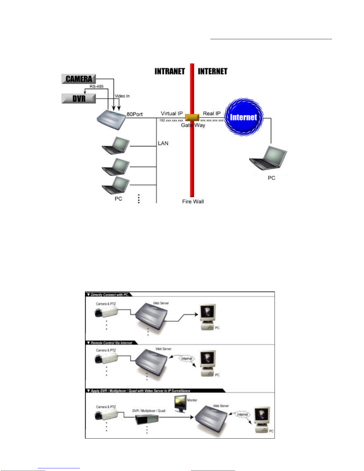
HARDWARE CONNECTION AT SERVER SITE:
A . Connection Structure
NOTE: The RS -485 to control
the DVR is optional.
1. Connect the video output of the camera or DVR to the video input of the Video Web Server.
2. Connect the PC to the Video Web Server for IP setting.
3. Connect the Video Server to the ADSL or CABLE MODEM with a Static IP address.
4. Connect PC with Internet and remote control Video Web Server.
B .Connection Application
-5-
Page 10
STEP 1: SOFTWARE INSTALLATION – STATIC IP SETTING:
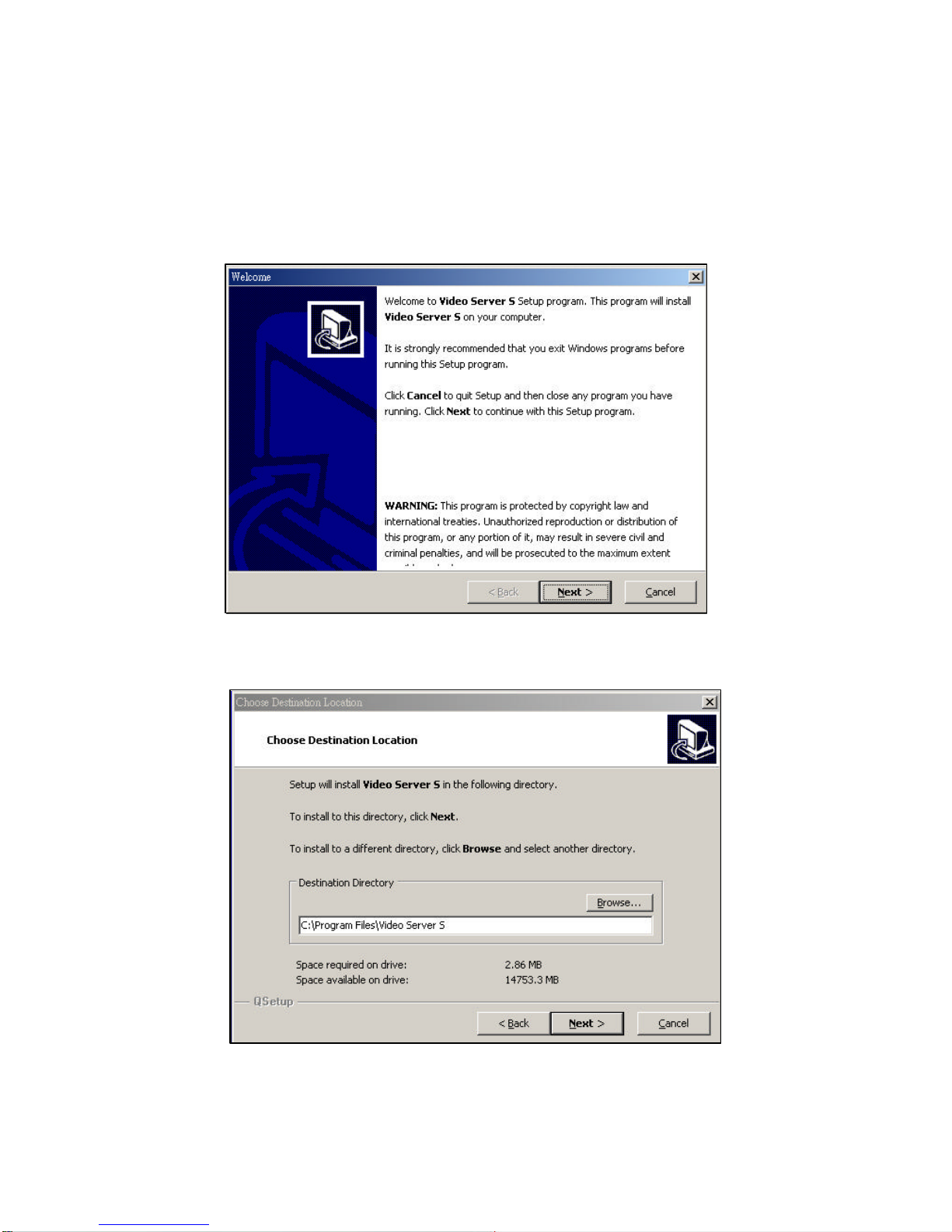
1. Put the attached CD into the CD-ROM. The application program will install on your PC.
Note: The CD contains a self-running installation that automatically starts when the CD is
inserted. Follow the instructions for installation as indicated in the next few pages.
2. Press “Next”.
3. Choose the destination location and press “Next”.
-6-
Page 11
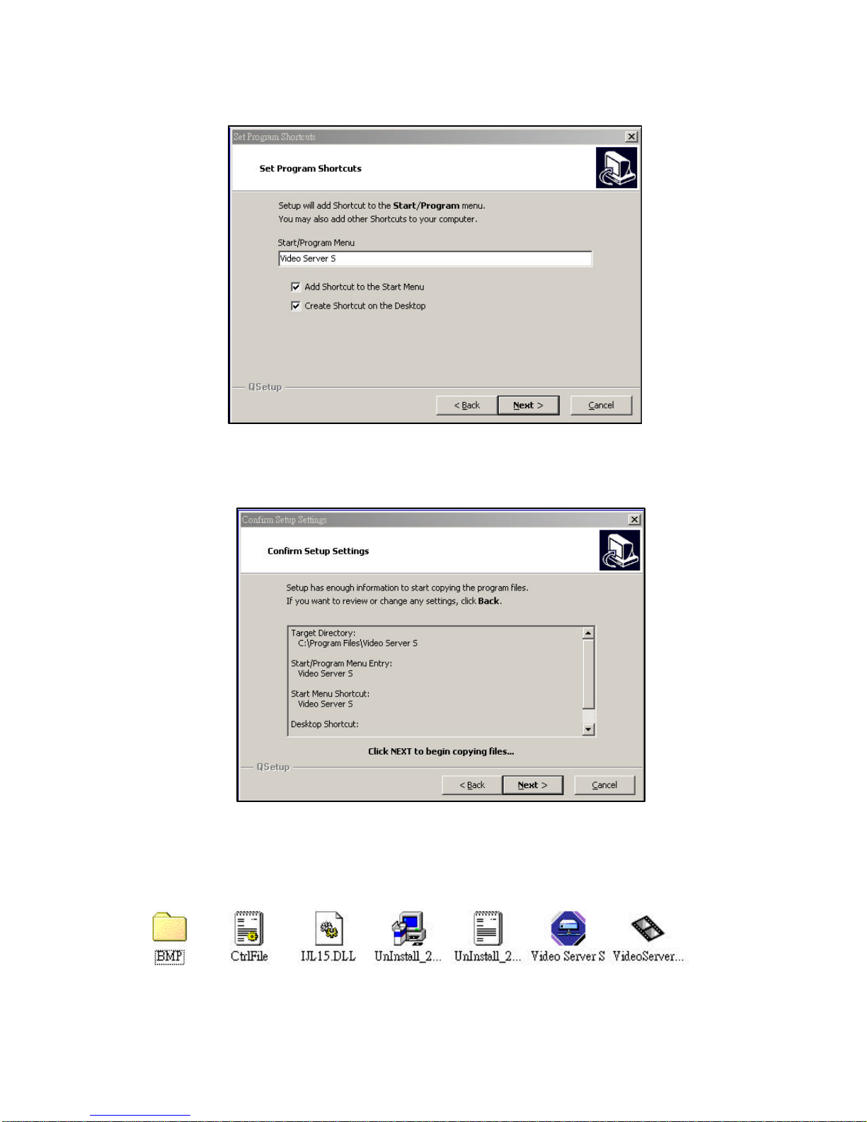
4. Set the program shortcut setting and press “Next”.
5. Press “Next” to begin copying the files
6. After the installation, the following files listed below will appear in your assigned path or
file folder. There will be 6 files and 1 folder.
-7-
Page 12
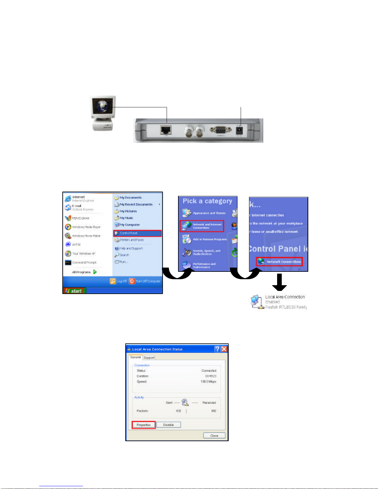
STEP 2: IP SETTING
1. Using the Crossover LAN cable connect the Video Web Server to the PC.
Note : In some operating environments, users might need the standard CAT5 cable.
RJ-45 POWER
2. Network setting for the PC. (The instruction is based on Win XP O/S. If your Operating
System is Win 2000 or Win 2003, the setup procedure is similar to that of Win XP O/S.)
3. Click on “Properties” for TCP/IP setup
Click twice
-8-
Page 13
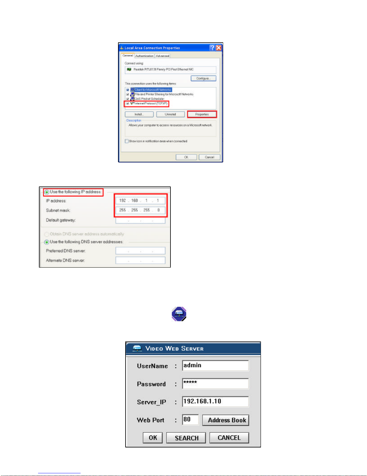
4. Click on “INTERNET PROTOCOL (TCP/IP)” and then select “Properties” to setup
5. Click on “Use the following IP address” and set the IP address and subnet mask
NOTE :
1. Before changing the PC network setting,
please write down the original network
setting in order to recover the original
setting after the setup.
2. The IP address should be
192.168.1.XXX. The setting of “XXX”
could be set from 1 to 254 Do not use 10
since 192.168.1.10 is the default IP ); the
subnet mask is 255.255.255.0.
STEP 3: VIDEO WEB SERVER SETTINGS
1. To configure the Server IP, please click twice to enter the setup.
2. Key in the User Name, Password, and Server IP (The default setting for the User Name is
admin and the default Password is admin ; Server IP is 192.168.1.10, Port : 80). Click on
OK to connect.
-9-
Page 14

3. When you see the control bar, this means that you have successfully logged into the
program on the Video Web Server. Click on “System Config” to set up.(NOTE: If you don’t
connect a camera or DVR to the Video Web Server, the only th ing you will see is the control
bar.)
SYSTEM CONFIG
4. In the Peripheral setting, set the baud rate, ID and model that you want to remotely
control later. Press the “APPLY” to enable the change after the setting.
5. Click on “System Config” again. In the Network setting, set the server IP, gateway, net
mask and DNS provided from your local ISP ( internet service provider ). Press
“APPLY” to enable the change after the setting.
-10-
Page 15

6. Disconnect the PC and Video Web Server, and link the static IP to the RJ-45 video web
server.
Static IP
STEP 4: DVR REMOTE SETTING
1. Connect the DVR and monitor.
2. In the “Remote” setting, set the baud rate and ID the same as the “Peripheral” setting
in the Video Web Server. Set the remote mode to RS-485 (see example below).
A. 1 / 4 CH DVR
B. 4 / 9 / 16 CH DMR
(MENU)
TIMER
CAMERA
RECORD
ALARM
DWELL
REMOTE
SYSTEM
EVENT
(MENU)
SEARCH
TIMER
RECORD
CAMERA
SYSTEM
EVENT
(REMOTE)
REMOTE MODE : RS-485
BAUD RATE : 2400
ID : 001
(SYSTEM)
:
:
REMOTE MODE : RS-485
BAUD RATE : 2400
REMOTE ID : 001
-11-
Page 16

STEP 5: PIN CONFIGURATIONS
After the remote setting, connect the DVR, noting the following pins.
PIN 1, 6. RS485-A, RS485-B
Use RS485-A & RS485-B serial communication signals to control digital units such as a
DVR.
PIN 4, 7, 8, 9. ALARM INPUT
Use PIN 4,7,8,9 to receive the alarm input and then trigger the Video Server to send Email to users for the auto e-mail warning system. (Alarm 1, 2 are for CH1; alarm 3, 4 are
for CH2)
PIN 5. GND
Ground
PIN 2, 3. NORMAL HIGH, NORMAL LOW
Use PIN 2 or 3 to trigger an external device.
Please see the example picture below for a 1CH/4CH DVR.
RS485-A
RS485-B
-12-
Page 17

STEP 6: CONNECTING TO A PC VIA THE INTERNET
1. Change the PC network setting to the original setting and link the PC to the internet.
2. Click twice to enter your User name & Password (Note : The default User
Name and Password are both “admin”), and the static IP, which you have set for the
Video Web Server in step 4.5. Then click OK to connect.
-13-
Page 18

WHAT IS A DYNAMIC IP ADDRESS ?
A Dynamic IP Address is an IP (Internet Protocol) address that changes each time you
connect to the internet. This cuts down on the number of IIP addresses large consumer
providers need because not all of their customers are using the service at any given time. It
also cuts down on bandwidth usage by preventing consumers from h osting servers. Note: a
number of companies have started to offer services aimed at updating DNS for dynamically
connected clients.
STEP 1: SOFTWARE INSTALLATION – DYNAMIC IP SETTING:
Follow the same procedure as outlined on Page 6 & 7 for the Stat ic IP Setting
STEP 2: SYSTEM RESET:
Before using the Video Web Server, please connect the power to t he Video Web
Server and push the button under the unit for more than 5 seconds to reset the
setting. See the photo below
STEP 3: DDNS REGISTRATION FOR A DYNAMIC IP ADDRESS:
1. You must have a gateway router that supports DDNS (Dynamic Domain Network Service).
Please go to www.dlink.com or www. linksys.com for a list of available routers
2. To register for a dynamic IP address click on the free site “http://www.dyndns.org” and
click on “Account” (please look at the example below).
-14-
Page 19

2. Click on “Create Account”
3. Register your information (Username, E-mail address & password). Click on
“Create Account” when the necessary information is completed
4. After registering your account, you will receive an e-mail, which contains instructions
to activate your account. If you do not follow these directi ons within 48 hours, you will
need to re-register your account.
5. Login your account.
-15-
Page 20

6. Click on“Account” and “Add Host”
7. Users can set up their own DDNS HOST. For example, the user’s Host name is
“avtech.dyndns.org”. Click on “Add Host ” to finish the setting. (NOTE : Some
routers don’t support some DDNS HOSTs)
STEP 4: CONNECTING THE PC TO A ROUTER / ROUTER LOGIN:
NOTE : The following settings are different from router to router. Please read the instructions
on your router thoroughly.
1. Connect the PC to the router using the LAN cable(LAN end)
POWER
-16-
Page 21

2. Network setting for PC. (The instruction is based on Win XP O/S. If your O/S is Win
2000 or Win 2003, the setup procedure is similar to that of Win XP O/S.)
Click twice
3. Click on “Properties” for TCP/IP setup
-17-
Page 22

4. Click on “INTERNET PROTOCOL (TCP/IP)” and then select “Properties” to setup
5. Choose “Obtain an IP address automatically ”
6. Enter the “Command Prompt ”
-18-
Page 23

7. In the setting window, enter “ ipconfig” , and write down the router’s gateway(e.g.
192.168.1.1)
8. Close the window above. Enter the IP address ( router’s gateway: 192.168.1.1 ) to
log in to the router from the Internet Explorer. Enter the login web page and key in
the router’s user name and password.
STEP 5: ROUTER SETTING
NOTE : In the router setting, there are four steps to follow.
1. Dial setting
2. DHCP setting
3. Virtual server setting
4. DDNS setting
-19-
Page 24

1. Click on “INTERNET PORT” and choose your WAN type (e.g. PPPoE). Enter your
“User Name” and “Password” to dial up the dynamic IP address. Press save
Step 5 : Router Setting
after you set up.
2. Press “LOCAL PORT ” and set “Start IP address” and “Number of IP address”. (For
example, if the IP address of your Video Web Server is 192.168.1.10, then 10 is
excluded from the setting range) Press save after you finish setting up.
3. In the “ADVANCED SETUP / Virtual Server”. Choose “By Port ” and set the “Port
Number” to 80 for the Video Web Server. Set the “Local Server IP Address” to
192.168.1.10. (The default Video Web Server IP and port). Pr ess add & save after you
set up.
-20-
Page 25

4. In the “ADVANCED SETUP / Dynamic DNS”, key in the “DNS Account ”, “User
Name” and “Password” that you applied in step 3. Press save after you set up.
STEP 6 : IP SETTING
1. Connect the PC or Notebook to the Video Web Server using the crossover LAN cable.
Note: In some operating environments, users might need the standard CAT5 cable.
RJ-45 POWER
(MENU)
TIMER
CAMERA
RECORD
ALARM
DWELL
PIP
MOTION
DISPLAY
NETWORK
USER
SYSTEM
EVENT
PTZ
(NETWORK)
IP ADDRESS 061.066.138.074
NET MASK 255.255.255.000
GATEWAY 061.066.138.073
DNS 168.095.001.001
PORT 00080
RESET DEFAULT NO
In the DVR Menu, select “Network”
The following 5 network settings should be entered.
(please see the example)
-21-
Page 26

2. Network setting for PC. (The instruction is based on Win XP O/S. If your O/S is
Win 2000 or Win 2003, the setup procedure is similar to that onWin XP O/S.)
Click twice
STEP 7: VIDEO WEB SERVER SETTING
1. To configure the Server IP, please click twice to enter the setup.
2. Key in the User Name, Password, and IP address (The default setting for the User
Name and Password are both “admin”; IP address is 192.168.1.10, Port : 80). Click OK
to connect .
-22-
Page 27

3. When you see the control bar, you have successfully logged into the program on the
Video Web Server. Click on “System Config” to set up.
SYSTEM CONFIG
4. In the Peripheral setting, set baud rate, ID and the model that want to remotely control
later. Press “APPLY” to enable the change after the setting.
5. Click on “System Config” again. In the Network setting, set the gateway the same as the
router’s gateway(192.168.1.1). Press “APPLY” to enable the change after the setting.
-23-
Page 28

STEP 8: DVR REMOTE SETTING
1. Connect the DVR and monitor.
2. In the “Remote” setting, set the baud rate and ID the same as the “Peripheral” setting
on the video web server. Set the remote mode to RS-485.(see example below)
A. 1 / 4 CH DVR
B. 4 / 9 / 16 CH DMR
(MENU)
TIMER
CAMERA
RECORD
ALARM
DWELL
REMOTE
SYSTEM
EVENT
(MENU)
SEARCH
TIMER
RECORD
CAMERA
SYSTEM
EVENT
(REMOTE)
REMOTE MODE : RS-485
BAUD RATE : 2400
ID : 001
(SYSTEM)
:
:
REMOTE MODE : RS-485
BAUD RATE : 2400
REMOTE ID : 001
STEP 9: PIN CONFIGURATIONS
After the remote setting, connect the DVR, noting the following pins below
A normally open contact/sensor can be connected to Pin 4 ,5.7,8 & 9, where Pin 5 is
Nomally open (Ground) and Pin 4,7,8 & 9 are Common (Alarm Input 1-4)
PIN 1, 6. RS485-A, RS485-B
Use the RS485-A & RS485-B serial communication signals to control digital units, such
as a DVR.
PIN 4, 7, 8, 9. ALARM INPUT
Use the PIN 4,7,8,9 to receive the alarm input and trigger the Video Server to send mail
to users for the auto e-mail warning system. (Alarm1, 2 are for CH1; alarm3, 4 are for
CH2)
-24-
Page 29

PIN 5. GND
Ground
PIN 2, 3. NORMAL HIGH, NORMAL LOW
Use PIN 2 or 3 to trigger an external device
Please see the example picture below for 1CH/4CH DVR.
Video Web Server
RS485-A
1CH/4CH DVR.
RS485-B
STEP 10: CONNECTING ALL DEVICES
ADSL modem
(WAN end)
DVR
STEP 11: CONNECTING TO A PC VIA THE INTERNET
1. Change PC network setting to the original setting and link PC to the internet.
2. Click twice and enter your User name, Password and host on the Video
Web Server. (Note : If you did not change the “Account” , the User Name and
Password are both “admin”). Click OK to connect.
DDNS HOST
-25-
Page 30

SOFTWARE OPERATION AT THE REMOTE SITE
Follow the steps below to connect to a remote site. (e.g. If you set up the server at
your office with one static ADSL, you can remotely watch the video anywhere, with a
networkable computer.)
Step 1: Click twice to enter the Login setup (please refer to “software installation ”)
Step 2: Key in “User Name” and “ Password”. (e.g. “User Name” and “Password” is
“dan”, and the IP address is 61.222.50.174). Click “OK” to establish the connection.
NOTE:
1.There are two ways to get the software,
one is via the attached CD, the other
is via the Video Web Server. (Refer to
APPENDIX#3)
2.You can press the “Address Book”
button to add a new IP into this
table or choose any login IP
address to access the Video Server.
3.This function is designed to store
a list of IP addresses which you
can control and manage.
Step 3: If you see the video screen, then you have successfully connecting to the server.
-26-
Page 31

CONTROL PANEL AND BASIC OPERATION
A. Video Web Server control panel B. Digital device control panel
1 2
3 4 9765 8 10 11 12 13
1
2
3
4
5
6
1. Camera video inputs
2. Quad screen, 7-9-10-13-16 screen
3. Zoom, PIP, Select, Lock, Search, Enter
4. Stop, Record, Rewind, Fast Forward, Pause,
Slow, Play
5. Menu(Exit), Left, Right, Up, Down
6. Click on the arrow key to go to the “Video
14
1. Image transmission rate per second
Web Server Control Panel”
2. Video Channels
3. Data transmission rate
4. Connection/Disconnection
5. Resolution : VGAQVGA
6. Image quality : HighMiddle Low
7. Image adjusting : Brightness/ Contrast/ Saturation
8. IP address (last 3 digits are displayed)
9. Snapshot : Press this button to automatically save the
image on your PC.
10. Record : Press this button to record the files & save them
on your PC
11. System setting
12. Number of online users
13. Window adjust ( right click for Full Screen)
NOTES
1.When you setup the video input from
the DVR, the screen will show the
operation interface, shown above.
2.Use the 16 CH DVR to explain the
operation (please refer to the
DVR user manual & APPENDIX#1 for
details)
3.After you press the record icon, there
will be a recorded file on your PC.
Each recording file can save up
to 6000 frames.
The recording file will be assigned
to the second file if it is more than
6000 frames.
If the HDD space is less than 200MB,
the program will stop recording.
14. Click on the arrow key to go to the “Digital Device Control
Panel”.
-27-
Page 32

PLAYBACK OPERATION
You will find the recorded file on the PC. Click twice to playback.
1 2
4 5 6 7
3
9
8
10 11
12
1. On Screen Display
2. Snapshot
3. Stop
4. Pause
5. Slow (1/2, 1/4, 1/8)
6. PLAY
7. Fast
8. OSD show / hide
9. System setting (Path of snapshot,
text color, progress color, channel
color)
10. Back Video
11. Next Video
12. Playback controlling bar
-28-
Page 33

ADVANCED SETTINGS
Click on “System Config” for advanced setting.
SYSTEM CONFIG
NETWORKNETWORK
NOTE :
Apply--
After all setting changes, press “apply” to
refresh the data in the Video Web Server.
Reboot--
Press this button to restart the Video Web
Server.
To set up the network setting of the
Video Web Server, check with your
network administrator or Internet
Service Provider.
1. You can get all the information, Server
IP, Gateway, Net Mask & DNS, from your
ISP company.
2. Web Port : You can control the Video Web
server via this port.
MAILMAIL
3. Mac : The equipment’s physical address.
4. IP Type : This unit only supports Static
IP address, if you want to use Dynamic
IP, please obtain through a Router.
When the alarm is triggered, the Video Web
Server will capture the instant picture and e-mail
the captured image to the assigned recipients.
1. You can get all the data from the ISP
company or by mailing to the server
supplier.(POP3/SMTP server)
2. You should set the mail list which you
want to send to when the alarm is
triggered.
3. If it is not necessary for you to verify
password and user’ s name, please
choose Verify as “No”.
4. Please refer to appendix#2 for more
details.
-29-
Page 34

FTPFTP
ACCOUNTACCOUNT
When the alarm is triggered, the video server
will capture the instant picture and upload the
captured image to the assigned FTP site.
1. You can get all the data from your MIS
department.
2. The default uploading port is No.21.
3. You can set the uploading directory
by yourself.
Set up the user’s account, password
(Max 5 accounts) and authority.
1. User’s level:
PERIPHERALPERIPHERAL
SUPERVISOR - controls all the functions
USER LEVEL - control advanced functions
GUEST LEVEL - control basic functions only
2. Live time : During this time period,
users are allowed to control the Video
Web Server.
You can set up all the peripheral setting in this
Windows. (Refer to APPENDIX#1 for more
details)
Peripheral Control : Set up the video input
device. You can select the devices and
set up “Baud Rate & ID No. ” to control the
equipment via the Video Web Server.
-30-
Page 35

FILE PATHFILE PATH
TOOLBOXTOOLBOX
You can modify the storing path for the
recording file and snapshot images .
Upgrade the firmware.
NOTE :
Do not reboot the Video Web Server while
it is upgrading the firmware.
ALARMALARM
1. Firmware Version : For the current
firmware version, you can click on the
“Find” button to get the latest firmware
from your PC. Press “Upgrade Firmware”
to upgrade it.
2.Turbo step: You can set the turbo step
when the turbo function is open.
Set up the ALARM function. You can use it
to operate the “alarm trigger recording ”
function.
1. Alarm : Enable or disable Alarm trigger
function.
2. Method : Two selections —Email or FTP.
3. Resolution : Image storing resolution for
Email or FTP function.
4. Alarm Duration : Alarm duration time.
5. Post Image : You can select how many
images you need to store when the alarm is
triggered.
6. Alarm record : Enable or disable “Alarm
trigger recording ” function.
7. Alarm refresh : Clean the alarm
message “ ” which is shown on the
screen.
-31-
Page 36

ONLINE USERONLINE USER
FAQ’S
Get online user’s information
1. Info refresh : Refresh the online users ’
information
1. With regards to direct connection to a PC, could I connect the video server with
remote PC without connecting it to the Internet ?
ANS: Yes, you can connect the Video server with remote PC using the Crossover
cable directly.
2. If Ido not have any network in my office or house, could I use this system?
ANS: Yes, you could use this unit. You can connect the Video Server with PC or
notebook directly, and take the PC as a storage device. Save all video from
your cameras and display the Video record on the PC.
3. Can I use ISDN to connect the Video Server?
ANS: Our Video Server could be connected via ADSL or CABLE modem. It does not
support ISDN connection. However, if you have a router which supports ISDN,
RJ-45 and port forwarding function, it can be used with our Video Server.
4. What kind of frame rate are we expecting?
ANS: The frame rate = band width(Kbps) / 8 / image size(Kbytes)-->Daytime
QVGA(Low-6 Kbytes, Middle-9 Kbytes, High-12 Kbytes),
VGA(Low-24 Kbytes, Middle-36 Kbytes, High-48 Kbytes).
-32-
Page 37

SPECIFICATIONS
Video Input
Watch Dog
Hardware
2 channels for analog and digital products, 1.0V p-p, Composite
BNC
4 inputsAlarm Input
Yes (this function keeps the Video Web Server working, and not
shut down)
YesRS-485 Port
Ethernet (10/100 Base-T)Network Interface
JPEGImage Compression
Brightness, Contrast, Saturation, Quality level adjustmentVideo Adjustment
TCP/IP, ICMP, FTP, HTTPProtocols
CPU: 16 Bits RISC Processor, ROM: 512K Bytes Flash, RAM: 8M
Bytes SDRAM
One RJ-45 for 10/100 Mbps Ethernet, LED to indicate Link/ Actual
Status
GPIO with triggers for E-mail or FTP site
6Max. # of remote accesses
10Max. # of user accounts
VGA: 640 x 480, QVGA: 32 0x 240Resolution
Up to 15/frames per second, 7.5 FPS/channelPerformance
64KMin. Bandwidth
Trigger & Action
Because our products are subject to continuous improvement, SVII and its subsidiaries reserve the right to
modify product design and specifications without notice and without incurring any obligation. E&OE
Triggered by GPIO Input, Action: E-mail images or images
uploading to the FTP sites specific account
Assign IP addressInstallation
Password ProtectionSecurity
12V / 500mAPower
-33-
Page 38

APPENDIX #1 – DVR CONTROL
PIN CONFIGURATIONS FOR CONNECTION TO A 1CH DVR
DVR
RS232-TX
GND
RS232-RX
RS485-B
VIDEO LOSS
RS485-A
SWITCH OUT
DISK FULL
ERROR OUT
ALARM RESET
REC STAR
ALARM INPUT
EXTERNAL ALARM NC
EXTERNAL ALARM COM
EXTERNAL ALARM NO
Web Server
GND
ALARM INPUT2
ALARM INPUT1
ALARM INPUT3
NORMAL LOW
ALARM INPUT4
NORMAL HIGH
RS485-B
RS485-A
PIN CONFIGURATIONS FOR CONNECTION TO 4CH, 9CH
DMR
& 16CH DMR
EXTERNAL ALARM NO
EXTERNAL ALARM COM
RS485-A
RS485-B
RS232-TX
RS232-RX
ALARM INPUT 1
ALARM INPUT 2
ALARM INPUT 3
ALARM INPUT 4
GND
Web Server
GND
ALARM INPUT 2
ALARM INPUT 1
ALARM INPUT 3
NORMAL LOW
ALARM INPUT 4
NORMAL HIGH
RS485-B
RS485-A
-34-
Page 39

2) Set the “Remote” function on the DVR.
NOTE : Remote mode : RS-485, Baud rate : selectable, ID : same as “Peripheral
Control” in the Video Web Server.
A. 1 / 4 CH DVR
(MENU)
TIMER
CAMERA
RECORD
ALARM
DWELL
REMOTE
SYSTEM
EVENT
B. 4 / 9 / 16 CH DMR
(REMOTE)
REMOTE MODE:RS-485
BAUD RATE:selectable
ID:020
(MENU)
SEARCH
TIMER
RECORD
CAMERA
SYSTEM
EVENT
(SYSTEM)
:
:
REMOTE MODE:RS-485
BAUD RATE:selectable
REMOTE ID:021
3) Set the “Peripheral Control” in the system configuration of the Video Web Server.
-35-
Page 40

APPENDIX #2 – SENDING E-MAIL
1) Connect the Sub-D plug on the Video Web Server with the COM/NO ports of the
Sensor.
Video Web Server
Please connect the N.O. end of sensor to ground (GND 5) and
connect the COM. end of the sensor to input end (4,7,8,9)
2) Set the “Mail setting” item in the system configure.
NOTE 1 : You can get all the data from the ISP ( Internet Service Provider) company or by
mailing to the server supplier (POP3/SMTP server).
NOTE 2 : You should set the mail list when the alarm is triggered.
NOTE 3 : When the alarm is triggered, you can find “ ” message showed on the screen.
The AP will start recording automatically and you can get the email with the
snapshot image in your mailbox.
-36-
Page 41

APPENDIX #3 – SOFTWARE DOWNLOAD
Step 1 : Please connect the PC to the Internet and key in the Video Web Server’s IP
address (ex : 61.222.50.160) in the browser. Then press ENTER.
Step 2 : Click on “Download Windows AP” to download the application program and save
“Setup.exe” in the HDD.
Step 3 : Click on “Setup.exe” twice to install the application program.
Step 4 Click on twice to enter the Login setup and refer to “software installation ”
for other operations.
-37-
Page 42

REFEFENCE NOTES :
Static IP
1. In step 2.5 : Please make sure that your IP address is 192.168.1.XXX. The
setting of “XXX” could be set from 1 to 254, where 10 is excluded (The
default IP is 192.168.1.10 )
2. In step 4.4 : Please make sure that the Peripheral setting is the same as the setting
on the DVR, which you want to remotely control later.
3. In step 6.2 : The Server IP is the IP you set in step 4.5.
Dynamic IP
1. In step 3.7 : Some routers don’t support the DDNS HOST.
2. In step 4.1 : Please use the router’s LAN end to connect to the PC.
3. In step 4.8 : Please use the IE(Internet Explorer) browser to enter the router’s gateway.
4. In steps 5.1- 5.4 : Please make sure that you press “save’ after you finish the setting.
5. In step 7.4 : Please make sure that the Peripheral setting is the same as the setting on the
DVR, which you want to remotely control later.
6. In step 10 : Please use the router’s LAN end to connect the Video Web Server. Use the
WAN end to connect to the ADSL modem.
7. In step 11.2 : The Server IP is the DDNS HOST, which you set in step 5.4.
Important Note: You must have a gateway router that supports DDNS (Dynamic
Domain Network Service). Please go to www. dlink.com or www.linksys.com for a list
of available routers
-38-
Page 43

CARE AND MAINTENANCE:
Please follow these instructions to ensure proper care and maint enance
of this system
Keep your monitor and camera dry. If it gets wet, wipe it dry immediately.
Use and store your unit in normal temperature environment. Extreme
temperatures can shorten the life of the electronic devices.
Handle the monitor carefully. Dropping it can cause serious damage
to the unit.
Occasionally clean the unit with a damp cloth to keep it looking new.
Do not use harsh chemicals, cleaning solvents, or strong detergents
to clean the unit.
Keep the unit away from excessive dirt and dust. It can cause
premature wear of parts.
-39-
 Loading...