

Lorex L22WD Series Quick Setup Manual
• 22” Widescreen LCD DVR
• HDD Pre-Installed*
• Mouse
• Remote Control
• Power Adaptor
PACKAGE CONTENTS:
ATTENTION:
• Broadband Router a nd Computer are requ ired for local and
remote monitorin g (not included).
• Lorex Client sof tware is compat ible with Window s XP™ and Vista™
operating sy stems.
• For detailed setup a nd software in formation, pleas e refer to
your printed User ’s manual (included).
• User Manual’s in addi tional languages , consumer guides and s torage
calculator are in cluded on your CD.
Information in th is document is subj ect to change wi thout notice. A s our product s are subject
to continuous im provement , Lorex Techno logy INC. an d our subsidi aries res erve the r ight to
modify p roduct design, specific ations and pri ces, wi thout n otice and withou t incur ring an y
obligation. E &OE © 2009 LO REX. All r ights res erved.
L22WD Series
Quick Setup Guide
under 30 minutesunder 15 minutes under 60 minutes
Hand Tools Hardware
Hi Speed
over 60 minutes
Skill Level
Time
under 30 minutesunder 15 minutes under 60 minutes
Hand Tools Hardware
Router
Hi Speed
over 60 minutes
Time: 20 Minutes
Hand Tools Skills - Easy
BAS IC I NST ALL AT ION G UI DE
SETUP YOUR MONITOR FIRST
STEP 1
NAVIGATION AND CONTROLS
STEP 2
Skill Level
Time
under 30 minutesunder 15 minutes under 60 minutes
Hand Tools Hardware
Router
Hi Speed
over 60 minutes
Time: 20 Minutes
Skills - Easy
BAS IC I NST ALL AT ION G UI DE
1
Connect the first camera to the CH1
input. Follow the same steps to
connect the additional cameras.
SET-UP LOCAL VIEWING ON YOUR PC
STEP 3
under 30 minutesunder 15 minutes under 60 minutes
Hand Tools Hardware
Hi Speed
over 60 minutes
Skill Level
Time
under 30 minutesunder 15 minutes under 60 minutes
Hand Tools Hardware
Router
Hi Speed
over 60 minutes
Time: 20 Minutes
Hand Tools Skills - Easy
BAS IC I NST ALL AT ION G UI DE
STEP 1
CONTINUED
LOC AL VI EW IN G I NS TAL LAT IO N GUI DE
Time: 30 Minutes
Skills - IntermediateHardware
PC/Router
Router
Hi Speed
over 60 minutes
Hi Speed
over 60 minutes
* Screen size, numb er of cameras, acce ssories and hard d rive capacit y
may vary by mod el. Check your pack age for specific conten t information.
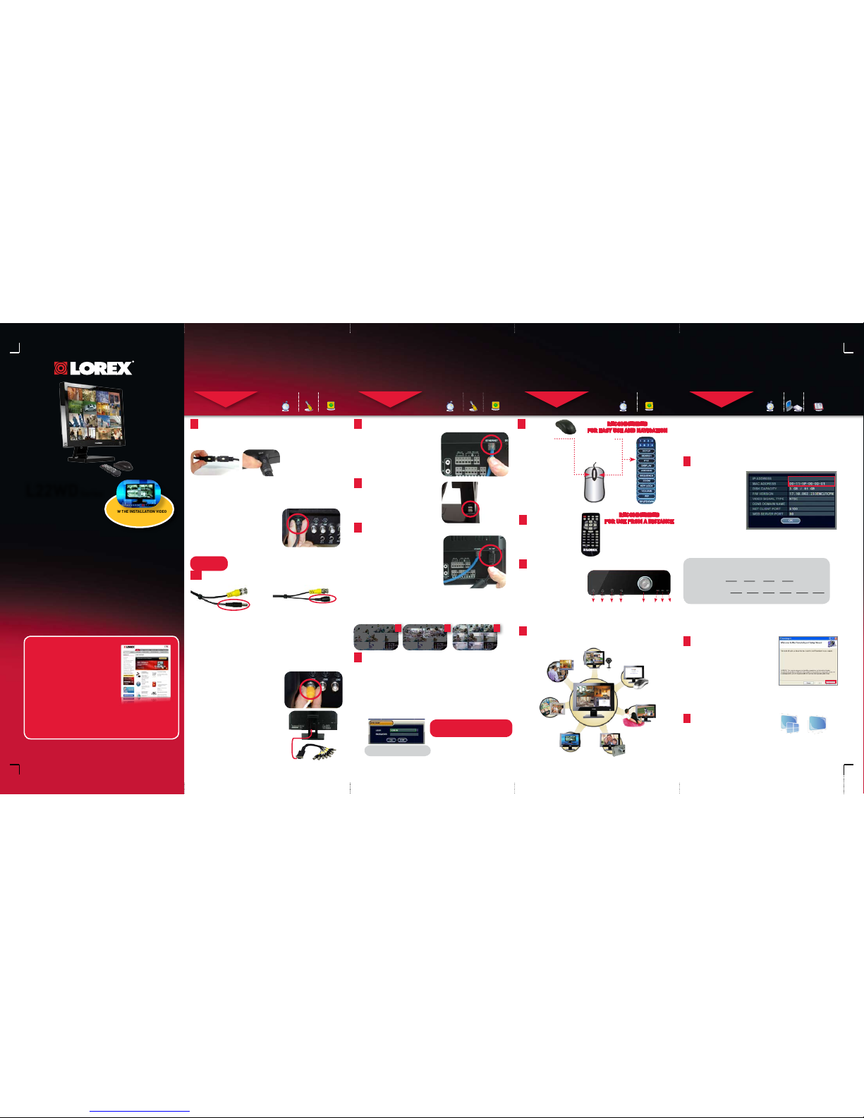
Connect DIN Cameras to the Monitor:
TIP: Test the cameras prior to selecting a permanent mounting
location by temporarily connecting the Cameras and Cables to
your System.
* Connect cameras to extension
cables by aligning the arrows.
Connect BNC Cameras to the Monitor:
If You are using BNC cameras:
1. Connect the extension cable to the Camera.
a. Connect the Male Power connector to
the Camera.
b. Connect the BNC connector to the Camera.
2. Connect the extension cable to the system.
a. Connect the BNC connector to an available
BNC port on the system.
b. Connect the Female Barrel Power
connector to a power adaptor.
3. Connect the Power Adaptor to a wall outlet.
ATTENTION: The ends of the extension cable are NOT the same - one
end has a Male power connector, and the other has a Female power
connector. Before permanently running the Camera Extension Cable,
make sure that the cable has been oriented between the Camera and
the unit correctly.
Male Power Connector - The
male power connector end of the
Extension cable connects to the
Camera.
OPTIONAL
NOTE: You cannot connect BNC and
DIN cameras to the same channel
simultaneously.
Female Power Connector - The
female power connector (barrel)
end of the Extension cable
connects to the Power Adaptor.
NOTE: The arrow mark
on top of the flat side of
the camera and cable
connectors should face
UP while inserting to the
Monitor.
1a
2
Connect one end of the Ethernet
cable (for remote monitoring) to
one of the router’s (not included)
LAN ports and the other end to
Monitor’s Network Port located at
the back of the Monitor.
Connect the Ethernet Cable:
Connect a USB mouse to one of
the USB ports located at the side
of the monitor.
Connect the Mouse:
3
Connect one end of the power
adaptor to the monitor and
the other end to an electrical
outlet.
NOTE: Your system will perform the follow-
ing System Check:
1. Blue LED at the front flashes four times
2. You will hear 2 beeps
3. Power LED at the front turns RED
Connect the Power Cable:
4
Setting the Date and Time:
5
Congratulations!
You have completed Step 1 successfully. You
can now view, record and playback images
on your system.
RECOMMENDED
FOR EASY USE AND NAVIGATION
1
Mouse:
2
Remote Control:
RECOMMENDED
FOR USE FROM A DISTANCE
THIS STEP RELATES TO REMOTE VIEWING OVER THE LAN (LOCAL
AREA NETWORK) BY USING A PC LOCATED ON THE SAME
NETWORK AS THAT OF THE SYSTEM.
*Your system MUST be connected to a Router prior to powering it ON.
NOTE: The system will lease networking information from your Router.
If you wish to set your information manually, then remove the from
DHCP option. Please consult your Hardware Manual for further Menu
options.
Record the IP and MAC Addresses in the section below:
IP ADDRESS : . . .
MAC ADDRESS : : : : : :
(Required for DDNS regist ration)
If the IP Address is 127.0.0.1 it means that you are either not connected
to your local network or your system is not in DHCP detect mode.
To retrieve the System
Information, press the
INFO button on the
Remote Control (ensure
batteries are inserted)
(or) Press the ENTER
button on the front panel
of the Monitor.
1
Retrieve System Information:
Click Next and follow the
installation screens to complete
Lorex Client Software installation.
2
Install Software:
(on your local computer for local viewing):
Insert the Lorex Client Software CD
into your local computer’s CD ROM.
SETUP YOUR MONITOR FIRST
Close the CD Menu Screen. Lorex
Client and Lorex Player icons will
appear on your desktop.
3
Lorex Client Software:
(on your local computer for local viewing):
It’s all on the Web
For detailed setup information,
please refer to your included
User’s Manual. For additional
information, please visit our
website www.lorexcctv.com
Email Support : support@lor excorp.com
Toll Free Technical Suppor t:
North Ameri ca: 1-888-42 LOR EX (1-888-425 -6739)
Mexico: 1-800-514 -6739
Toll Free Technical Suppor t - International (ou tside of North Am erica):
+800-425 -6739-0
(Example: From the U K, dial 00 instead of + )
Lorex Internati onal Website - ww w.lorexcctv.com
• Cameras & stands*
• Camera extension cables*
• Octopus Cable
• Ethernet cable
• Software application CD
• Quick Start Guide
The Octopus Cable (provided with the 16
channel system) allows 8 additional BNC
cameras to be added to the system
representing 9 and 16 channels.
NOTE: This may take up to 15 seconds. Please wait until the system completes
loading.
3
1 2
PRESS THE MONITOR POWER BUTTON ON - LOCATED ON THE
FRONT OF THE MONITOR. Your system will load with screens shown below.
Time and Date can be set by
• Pressing the SETUP button from the front panel of the monitor
• Pressing the SETUP button from the remote control (or) by
• Using the mouse navigation (recommended)
1. Right click the mouse and select SETUP and click on SYSTEM SETUP
2. On SYSTEM SETUP MAIN Menu, select SYSTEM
3. Click on the DATE/TIME Menu and use the UP and DOWN arrows to change the
DATE/TIME. NOTE: If the Date/Time is set into the past, a message will appear
warning that Overlapped date(s) will be erased.
4. Click APPLY. The system will prompt you for default USER ID and PASSWORD.
THE DEFAULT USER IS ADMIN
THE DEFAULT ADMIN PASSOWRD IS 1234
LEFT BUTTON -
• Click to select options
in Menu, Recording and
Search Mode.
• Click to change settings,
select dates and perform
other options.
• Double click on a Channel
in QUAD or other disply
views to view the single
camera in full screen.
RIGHT BUTTON -
• Opens a submenu
to access a list of
options:
3
Monitor Front Panel:
The Front Panel buttons can also
be used to access the menus and
configure the system.
1. System Power Button
2. Multi-function Menu Mode
3. Setup Menu
4. Return Button
5. Navigation & Enter Controls
6. Power LED
7. Record LED
8. Network LED
1 2 3 4 567 8
192.168.1.12
LOREX
LorexClient LorexPlayer
L22WD Series Quick Setup Guide - English - R1
4
Multifunction System/Modes:
Security
PC Monitor
Entertainment
Picture Frame
Installation
Guide
Public View
Monitor
Remote
Monitoring
VIEW THE INSTALLATION VIDEO
ON THE SYSTEM FOR QUICK &
EASY SET-UP
SET-UP LOCAL VIEWING ON YOUR PC
STEP 3
CONTINUED
SET-UP LOCAL VIEWING ON YOUR PC SET-UP INTERNET REMOTE SECURITY
MONITORING
STEP 4
SET-UP INTERNET REMOTE SECURITY
MONITORING
STEP 4
CONTINUED
SET-UP INTERNET REMOTE SECURITY
MONITORING
STEP 4
CONTINUED
LOC AL VI EW IN G I NS TAL LAT IO N GUI DE
Time: 30 Minutes
Skills - IntermediateHardware
PC/Router
Router
Hi Speed
over 60 minutes
Hi Speed
over 60 minutes
Hi Speed
over 60 minutes
REMOT E VIE WING INSTA LLATIO N GUI DE
Time: 60 Minutes
Skills - AdvancedHardware
PC/Router
Hi Speed
over 60 minutes
Hi Speed
over 60 minutes
REMOT E VIE WING INSTA LLATIO N GUI DE
Time: 60 Minutes
Skills - AdvancedHardware
PC/Router
Hi Speed
over 60 minutes
Hi Speed
over 60 minutes
REMOT E VIE WING INSTA LLATIO N GUI DE
Time: 60 Minutes
Skills - AdvancedHardware
PC/Router
Hi Speed
over 60 minutes
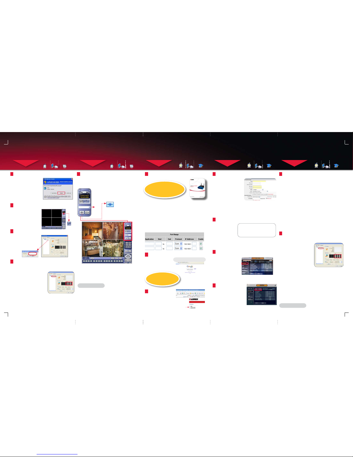
Double-click the Lorex Client
software icon on your desktop
to run the program.
4
Run the Lorex Client Software:
(on your local computer for local viewing):
Click the Setup icon from
the Lorex Client Software
Screen.
5
Lorex Client Set-up:
(on your local computer for local viewing):
Click on the SITE listing on the
Left Panel, and Right Click to
‘ADD GROUP’.
Enter a name for the GROUP,
and click OK.
6
Add ‘Group’:
(on your local computer for local viewing):
1. Enter a Name for the System.
2. Enter the IP Address recorded in
Step 2-1
3. Enter the Monitor TCP/IP port
(6100 by default).
4. Enter the User ID (ADMIN by
default), max. 5 characters.
5. Enter the Admin Password (1234
by default).
* User ID and Password are case
sensitive
6. Add cameras using the drop down
menus to assign camera positions.
1, 2, 3, 4 is set by default.
7. Click ADD to add the System Location.
8. Click OK
Select the GROUP you created and enter
SETUP information.
7
Enter Client Setup Information:
(on your local computer for local viewing):
STEP 3
CONTINUED
LOC AL VI EW IN G I NS TAL LAT IO N GUI DE
Time: 30 Minutes
Skills - IntermediateHardware
PC/Router
Router
Hi Speed
over 60 minutes
Hi Speed
over 60 minutes
Select the new Group you created using the drop down
menu (1) and press the CONNECT button (2) to connect to
the LOCAL LIVE site.
Please refer to the Lorex Client section in your user manual to
learn more about the Lorex Client, Lorex Player and the Storage
Calculator.
LOCAL LIVE SITE*
*For viewing your system in your local area network (LAN)
8
View Cameras Locally:
(on your local computer for local viewing):
Congratulations!
You have completed Step 3 successfully.
You can now view, playback images and
remotely control your system on your
local computer over the Local Area
Network (LAN).
Port forward your router first before proceeding
with the set-up
A router configuration guide featuring the most commonly used
routers in the market is available on your Lorex Client Software
CD and also on www.lorexcctv.com/support in the Consumer’s
Guide Section.
An example of a port forwarding screen is shown for illustration
purposes.
System
System
6100 6100
80 80
12
12
EXAMPLE
1
You must forward Ports:
6100 (TCP/IP)
80 (WEB)
All routers are different. To port forward your router, please
refer to your router’s user manual.
http://www.lorexddns.net
DDNS (Dynamic Domain Name System) Set-up:
Open your web browser
(Internet Explorer by
default) and enter
www.lorexddns.net
in the address bar.
2
LOREX PROVIDES A FREE
DDNS SERVICE WITH THIS
SYSTEM.
Create Account
Click the CREATE ACCOUNT
option.
Create Account:
3
1. FOR PRODUCT LICENSE
select the L22WD option
from the drop down menu.
2. FOR PRODUCT CODE
enter the Monitor’s MAC
address (recorded in step
3 - 1) without the dashes.
1
2
3
VISIT
WWW.LOREXCCTV.COM/SUPPORT
TO VIEW THE ROUTER CONFIGURATION
GUIDE
4
Complete New Account Information:
An automated
REGISTRATION
CONFIRMATION EMAIL
will be sent to your
email. Print and Save
this confirmation. You
will need this
information to access
your System remotely.
DDNS Domain Name: ddns .lorexddns.net
Domain: tomsmith.lorexddns.n et
User ID: tomsmith
Password: (your password)
5
Registration Email:
Mouse navigation (recommended)
1. Right click the mouse
and select SETUP and
click on SYSTEM SETUP
2. On SYSTEM SETUP MAIN
Menu, select SYSTEM
3. Click on NETWORK to
enable and add DDNS
information.
6
Enter DDNS Set-up on your System:
On the NETWORK menu, use the
DOWN arrow key to navigate to
DDNS. Highlight DDNS checkbox
by pressing ENTER and press the
UP arrow key to put a check mark
in the DDNS checkbox. Press
ENTER to accept settings.
7
Enable DDNS Settings:
1. Scroll down to the DDNS SERVER within the NETWORK menu and
press ENTER.
2. DDNS Server Names: LOREX (by default)
3. Enter the DOMAIN NAME sent to you in the REGISTRATION
CONFIRMATION EMAIL (i.e.tomsmith.lorexddns.net) leaving out the
.lorexddns.net part of the URL.
4. Enter the USER ID sent to you in the REGISTRATION
CONFIRMATION EMAIL.
5. Enter your PASSWORD (from the DDNS Registration Email sent to
you).
6. Click the DDNS Status button - a SUCCESS message will appear if
the settings are correct.
7. Scroll to OK button and press ENTER to accept.
8. On the SYSTEM menu screen scroll down to APPLY and press
ENTER.
9. The system will now ask you to RESTART. Click OK.
8
Set the DDNS Settings:
Repeat Steps 3-2 to 3-6 to install, run, and set-up Lorex Client
Software on your REMOTE COMPUTER for remote viewing.
9
NOTE: The DDNS service supports Dynamic IP addresses for remote connection.
When this feature is configured on the remote system, you can access it remotely
using the domain name instead of IP address. To use this feature, the system
must be registered on the Lorex DDNS server. Alternatively, if you have a static
IP address you can enter it here. Please refer to the LOREX CLIENT Manual for
network setup and configuration.
1. Enter a Name for the System
2. Enter the DDNS DOMAIN NAME
from the Registration Email sent
to you.
3. Enter the Monitor TCP/IP port
(6100 by default)
4. Enter the User ID (ADMIN by
default), max. 5 characters
5. Enter the Admin Password (1234
by default)
* User ID and Password are case
sensitive
6. Add cameras using the drop down
menus to assign camera positions
7. Click ADD to add the System
Location
8. Click OK
Select the GROUP you created and enter SETUP information.
Enter Client Setup Information:
(on your remote computer for remote viewing):
Repeat Step 3-8 to view cameras on your
remote computer.
Congratulations!
You have completed Step 4 successfully.
You can now view, playback images and
remotely control your system on your
Remote computer over the internet.
3. FOR URL REQUEST enter a unique URL name (e.g. tomsmith).
Note: URL name should not be more than 15 characters.
TAKE THIS OPPORTUNITY TO
REGISTER YOUR PRODUCT FOR
WARRANTY AND PRODUCT
UPDATES.
NOTE: When you run LorexClient on your PC
for the first time, you may see the Windows
Security Alert. Please click unblock to run
the application. (on Windows Vista™ select
“Allow”).
SET-UP
BUTTON
OFFICE
7
System
192.168.1.12
6100
ADMIN
****
8
1
2
3
4
5
6
7
System
tomsmith
6100
ADMIN
****
8
1
2
3
4
5
6
L22WD Series Quick Setup Guide - English - R1
CONNECT BUTTON
1
2
 Loading...