

Page 1
SURVEILLANCE RECORDER
WITH MOTION DETECTION
Instruction Manual
DIGITAL VIDEO
AND AUDIO RECORDING
English Version 3.0
Version française 1.0
Versión en español1.0
MODELS:
L200 Series
Includes L204 & L208
Copyright © 2008 Lorex Technology Inc.
www.lorexcctv.com
Page 2
EN
p
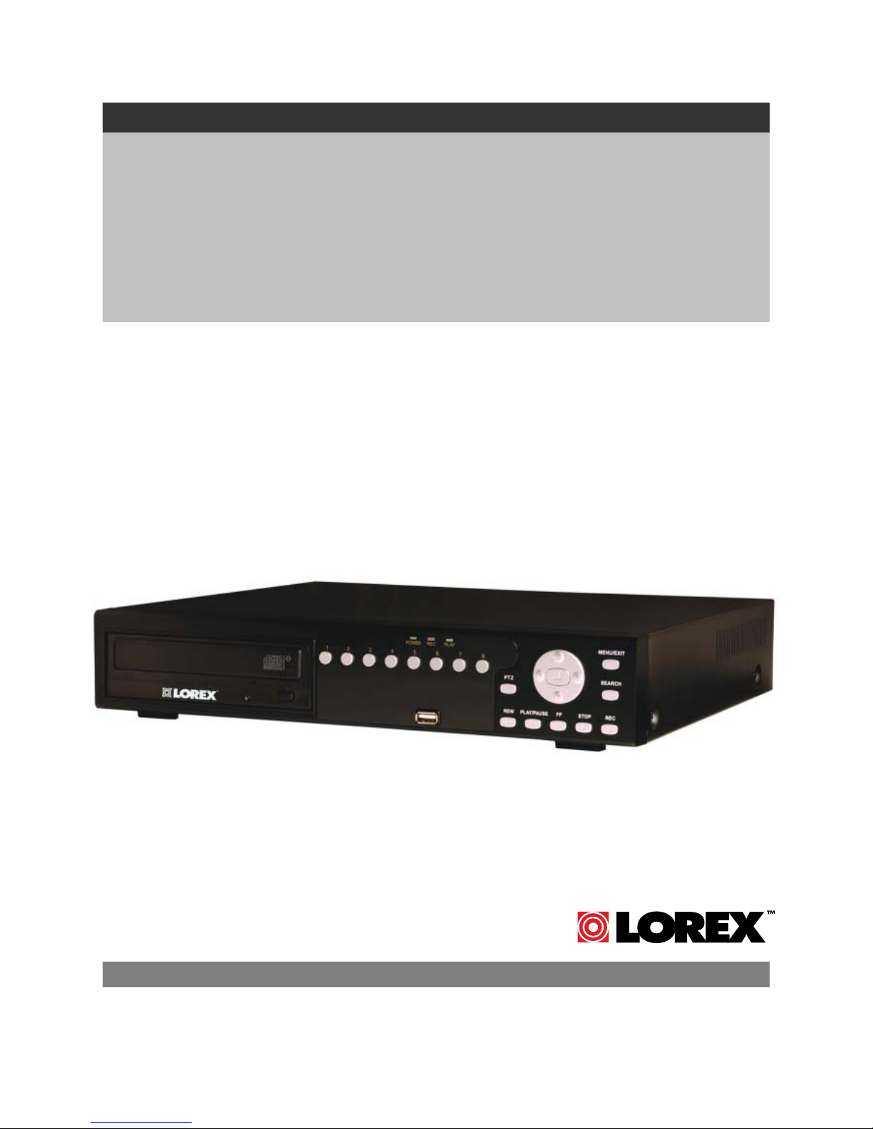
Thank you for purchasing the L200 Series Surveillance DVR. Lorex is committed to providing our
customers with a high quality, reliable security product.
The L200 series of Surveillance Digital Video Recorders provides professional grade features in a
value package. Available in 4 and 8 channel models, the L200 series supports high quality video and
audio recording, up to 1 Terabyte of internal data storage*, optical drive (CD/DVD-RW) backup* of
critical video, USB back up and network support for local and remote viewing on a PC. This full
featured series of DVRs also support composite and VGA output for viewing on any monitor, PTZ
camera control, IR controller and PS/2 mouse navigation*.
To learn more about the L200 Series Surveillance DVR, and to learn about our complete range of
accessory products, please visit our website at:
http://www.lorexcctv.com
* optional components – actual components may vary.
CAUTION
RISK OF ELECTRIC SHOCK
DO NOT OPEN
CAUTION: TO REDUCE THE RICK OF ELECTRIC SHOCK
DO NOT REMOVE COVER (OR BACK).
NO USER SERVICABLE PARTS INSIDE.
REFER SERVICING TO QUALIFIED SERVICE PERSONNEL.
The lightning flash with arrowhead symbol, within an
equilateral triangle, is intended to alert the user to the
presence of uninsulated “dangerous voltage” within the
products ‘ enclosure that may be of sufficient magnitude
to constitute a risk of electric shock
The exclamation point within an equilateral triangle is
intended to alert the user to the presence of important
operating and maintenance (servicing) instructions in the
literature accompanying the appliance.
WARNING: TO PREVENT FIRE OR SHOCK HAZARD, DO NOT
EXPOSE THIS UNIT TO RAIN OR MOISTURE.
CAUTION: TO PREVENT ELECTRIC SHOCK, MATCH WIDE BLADE
OF THE PLUG TO THE WIDE SLOT AND FULLY INSERT.
Please visit us on the web for the most current Manuals, Quick Start Guides and Firmware.
Additional Language Manuals are also available at:
2
://www.lorexcctv.com
htt
Page 3
p
Important Safeguards
Important Safeguards
In addition to the careful attention devoted to quality standards in the manufacture process of your video
product, safety is a major factor in the design of every instrument. However, safety is your responsibility
too. This sheet lists important information that will help to assure your enjoyment and proper use of the
video product and accessory equipment. Please read them carefully before operating and using your
video product.
Installation
EN
1. Read and Follow Instructions - All the
safety and operating instructions should be
read before the video product is operated.
Follow all operating instructions.
2. Retain Instructions - The safety and
operating instructions should be retained for
future reference.
3. Heed Warnings - Comply with all warnings
on the video product and in the operating
instructions.
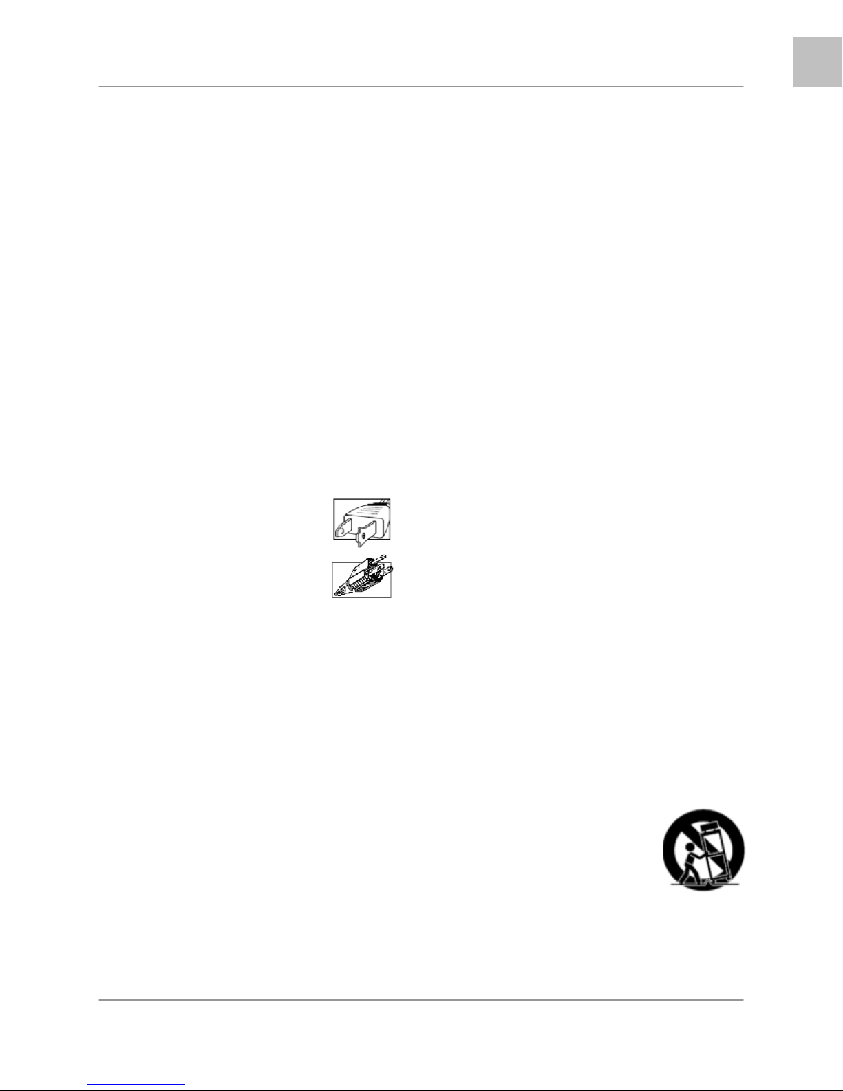
4. Polarization - Do not defeat the safety
purpose of the polarized or grounding-type
plug.
o A polarized plug has two blades with
one wider than the other.
o A grounding type plug has two
blades and a third grounding prong.
o The wide blade or the third prong is
provided for your safety.
o If the provided plug does not fit into
your outlet, consult an electrician for
lacement of the obsolete outlet
re
5. Power Sources - This video product should
be operated only from the type of power
source indicated on the marking label. If you
are not sure of the type of power supply to
your location, consult your video dealer or
local power company. For video products
intended to operate from battery power, or
other sources, refer to the operating
instructions.
6. Overloading - Do not overload wall outlets of
extension cords as this can result in the risk
of fire or electric shock. Overloaded AC
outlets, extension cords, frayed power cords,
damaged or cracked wire insulation, and
broken plugs are dangerous. They may result
in a shock or fire hazard. Periodically examine
the cord, and if its appearance indicates
damage or deteriorated insulation, have it
replaced by your service technician.
7. Power-Cord Protection - Power supply
cords should be routed so that they are not
likely to be walked on or pinched by items
placed upon or against them, paying
particular attention to cords at plugs,
convenience receptacles, and the point where
they exit from the video product.
8. Ventilation - Slots and openings in the case
are provided for ventilation to ensure reliable
operation of the video product and to protect
it from overheating. These openings must not
be blocked or covered. The openings should
never be blocked by placing the video
equipment on a bed, sofa, rug, or other
similar surface. This video product should
never be placed near or over a radiator or
heat register. This video product should not
be placed in a built-in installation such as a
bookcase or rack unless proper ventilation is
provided or the video product manufacturer’s
instructions have been followed.
9. Attachments - Do not use attachments
unless recommended by the video product
manufacturer as they may cause a hazard.
10. Water and Moisture - Do not use this video
product near water. For example, near a bath
tub, wash bowl, kitchen sink or laundry tub, in
a wet basement, near a swimming pool and
the like.
Caution: Maintain electrical safety. Power line
operated equipment or accessories
connected to this unit should bear the UL
listing mark of CSA certification mark on the
accessory itself and should not be modified
so as to defeat the safety features. This will
help avoid any potential hazard from electrical
shock or fire. If in doubt, contact qualified
service personnel.
11. Accessories - Do not place this video
equipment on an unstable cart, stand, tripod,
or table.
The video equipment may fall,
causing serious damage to the
video product. Use this video
product only with a cart, stand,
tripod, bracket, or table
recommended by the
manufacturer or sold with the
video product.
Any mounting of the product should follow
the manufacturer’s instructions and use a
mounting accessory recommended by the
manufacturer.
3
Page 4

EN
Important Safeguards
Service
13. Servicing - Do not attempt to service this
video equipment yourself as opening or
removing covers may expose you to
dangerous voltage or other hazards. Refer all
servicing to qualified service personnel.
14. Conditions Requiring Service - Unplug this
video product from the wall outlet and refer
servicing to qualified service personnel under
the following conditions.
A. When the power supply cord or plug is
damaged.
B. If liquid has been spilled or objects have
fallen into the video product.
C. If the video product has been exposed to
rain or water.
D. If the video product does not operate
normally by following the operating
instructions. Adjust only those controls
that are covered by the operating
instructions. Improper adjustment of
other controls may result in damage and
will often require extensive work by a
qualified technician to restore the video
product to its normal operation.
E. If the video product has been dropped or
the cabinet has been damaged.
F. When the video product exhibits a
distinct change in performance. This
indicates a need for service.
15. Replacement Parts - When replacement
parts are required, have the service
technician verify that the replacements used
have the same safety characteristics as the
original parts. Use of replacements specified
by the video product manufacturer can
prevent fire, electric shock or other hazards.
16. Safety Check - Upon completion of any
service or repairs to this video product, ask
the service technician to perform safety
checks recommended by the manufacturer to
determine that the video product is in safe
operating condition.
17. Wall or Ceiling Mounting - The cameras
provided with this system should be mounted
to a wall or ceiling only as instructed in this
guide, using the provided mounting brackets.
18. Heat - The product should be situated away
from heat sources such as radiators, heat
registers, stoves, or other products (including
amplifiers) that produce heat.
Use
19. Cleaning - Unplug the video product from the
wall outlet before cleaning. Do not use liquid
cleaners or aerosol cleaners. Use a damp
cloth for cleaning.
20. Product and Cart Combination - Video and
cart combination should be moved with care.
Quick stops, excessive force, and uneven
surfaces may cause the video product and
car combination to overturn
21. Object and Liquid Entry - Never push
objects for any kind into this video product
through openings as they may touch
dangerous voltage points or “short-out” parts
that could result in a fire or electric shock.
Never spill liquid of any kind on the video
product
22. Lightning - For added protection for this
video product during a lightning storm, or
when it is left unattended and unused for long
periods of time, unplug it from the wall outlet
and disconnect the antenna or cable system.
This will prevent damage to the video product
due to lightning and power line surges. The
manufacturer’s instructions and use a
mounting accessory recommended by the
manufacturer.
4
Page 5

General Precautions
General Precautions
1. All warnings and instructions of this manual should be followed
2. Remove the plug from the outlet before cleaning. Do not use liquid aerosol detergents. Use a water
dampened cloth for cleaning
3. Do not use this unit in humid or wet places
4. Keep enough space around the unit for ventilation. Slots and openings in the storage cabinet should
not be blocked
5. During lightning storms, or when the unit is not used for a long time, disconnect the power supply,
antenna, and cables to protect the unit from electrical surge
FCC CLASS B NOTICE
Note:
This equipment has been tested and found to comply with the limits for a Class B digital device,
pursuant to Part 15 of the FCC Rules. These limits are designed to provide reasonable protection
against harmful interference in a residential installation. This equipment generates, uses, and can
radiate radio frequency energy and, if not in-stalled and used in accordance with the instruction, may
cause harmful interference to radio communications.
However, there is no guarantee that interference will not occur in a particular installation. If this
equipment does cause harmful interference to radio or television reception (which can be determined
by turning the equipment on and off), the user is encouraged to try to correct the interference by one
or more of the following measures:
o Reorient or relocate the receiving antenna
o Increase the separation between the equipment and receiver
o Connect the equipment into an outlet on a circuit different from that to which the receiver
is connected
o Consult the dealer or an experienced radio or television technician for assistance
EN
This equipment has been certified and found to comply with the limits regulated by FCC, EMC, and
LVD. Therefore, it is designated to provide reasonable protection against interference and will not
cause interference with other appliance usage.
However, it is imperative that the user follows this manual' guidelines to avoid improper usage which
may result in damage to the unit, electrical shock and fire hazard injury
In order to improve the feature functions and quality of this product, the specifications are subject to
change without notice from time to time.
LOREX TECHNOLOGY INC.
www.lorexcctv.com
5
Page 6

EN
L200 Series Features
L200 Series Features
• 4 or 8 Channel Triplex DVR (Simultaneously View, Record and Playback)
• Network ready (LAN support with remote client application)
• Efficient file transfer (MPEG4 network transmission)
• Excellent original image recording (MJPEG recording to disk)
• Connects to any monitor (VGA and composite monitor support)
• Easy file backup (Supports optional internal optical drive, USB, remote client recording)
• Large storage capacity (Supports 2 internal “security certified” disk drives up to 1TB total
• Pan-tilt-zoom camera control (RS485 interface)
• Multiple recording modes (continuous, motion, alarm sensor, schedule)
• Adjustable frame rate for each channel (optimize recording characteristics)
• Supports mouse navigation (easy operation)
• Alarm input-4/output-1 (connect to existing intruder alarm or alarm panel)
Connections:
• Up to 4 or 8 Cameras (depending on Model)
• BNC Cable Connectors
• Audio Input & Output
• Option for connection to any PC Monitor**
* Software is only compatible with Windows 2000 / Windows XP
** L200 Series supports VGA Connection (PC Monitor).
6
Page 7

Table of Contents
Table of Contents
L200 Series - Front .......................................................................................................................................9
L200 Series - Back......................................................................................................................................11
Remote Control ...........................................................................................................................................12
Mouse Control............................................................................................................................................. 13
Camera Installation ..................................................................................................................................... 14
Installation Warnings: .............................................................................................................................. 14
Camera Stand Installation: ......................................................................................................................14
Connecting BNC Cameras..........................................................................................................................15
Camera Connection Diagram.................................................................................................................. 15
Display Modes.............................................................................................................................................16
Initial Loading Sequence .........................................................................................................................16
General Display Overview.......................................................................................................................17
Camera Display Modes ...........................................................................................................................17
Onscreen Symbols – Channel Symbols.................................................................................................. 18
Onscreen Symbols – Status Bar .............................................................................................................18
System Setup Controls ...............................................................................................................................19
Menu Navigation Controls .......................................................................................................................19
Setup Menu - Options..............................................................................................................................19
System Menu Tree .................................................................................................................................. 20
RECORDING ..............................................................................................................................................34
SEARCH FUNCTION.................................................................................................................................. 35
SEARCH TYPES ........................................................................................................................................35
SEARCH TYPES ........................................................................................................................................36
VIDEO PLAYBACK .....................................................................................................................................36
VIDEO PLAYBACK .....................................................................................................................................37
BACK-UP VIA CD-R/W (OPTION).............................................................................................................. 38
FIRMWARE UPGRADE..............................................................................................................................39
PTZ (PAN/TILT-ZOOM) .............................................................................................................................. 40
Lorex Client Application ..............................................................................................................................41
PLAYER MODE....................................................................................................................................... 42
VIEWER MODE....................................................................................................................................... 51
DVR Specifications - Appendix #1 ..............................................................................................................60
Full Connectivity Diagram – Appendix #2................................................................................................... 61
Hard Drive Replacement - Appendix #3 .....................................................................................................62
Troubleshooting – Appendix #4 ..................................................................................................................64
Appendix #5 – Network Connectivity Overview ..........................................................................................66
Appendix #6 – PTZ Control......................................................................................................................... 71
Appendix #7 – Connecting Motion / Alarm Device .....................................................................................72
Appendix #8 – Initial Setup Menu Values ...................................................................................................73
EN
7
Page 8
EN
Getting Started
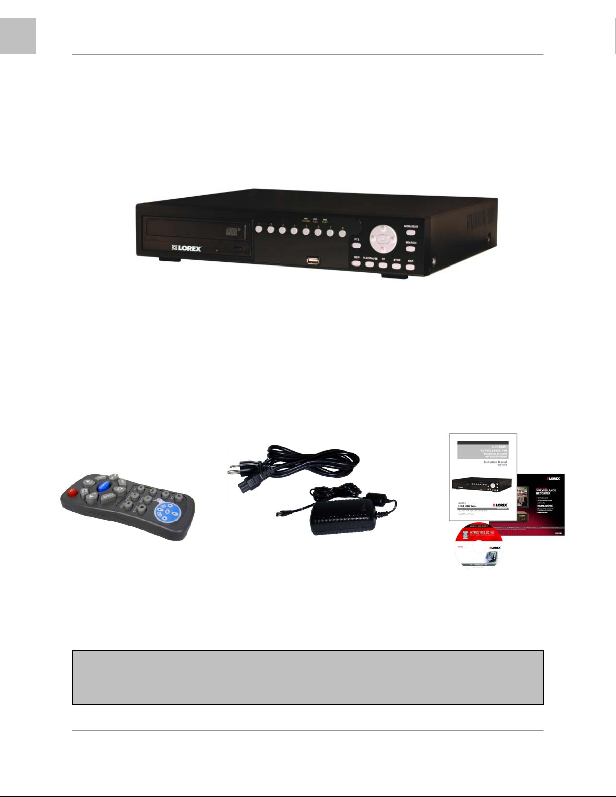
Getting Started
The DVR comes with the following components:
1 x COMPACT DIGITAL VIDEO RECORDER
(8 CHANNEL MODEL SHOWN)*
1 x REMOTE
CONTROL
*DVD-RW optional depending on model
CHECK YOUR PACKAGE TO CONFIRM THAT YOU HAVE RECEIVED THE COMPLETE
DVR, INCLUDING ALL COMPONENTS SHOWN ABOVE.
8
1 x POWER ADAPTOR
1 x POWER ADAPTOR CABLE
1 x HARDWARE MANUAL
1 x QUICK START GUIDE
1 x SOFTWARE CD
Page 9
L200 Series - Front
123 4 5
EN
L200 Series - Front
6
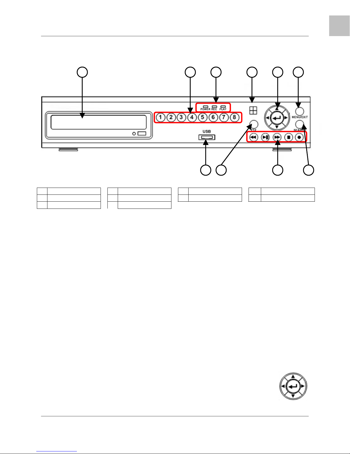
1 CD-DVD-RW* 4 IR Receiver 7 USB Port 9 Playback Controls
2 Channel Buttons 5 Navigation Control 8 PTZ Button 10 Search Button
3 LED Indicators 6 Menu/Exit Button
1. CD-DVD-RW DRIVE - *OPTIONAL: CD-DVD-RW drive optional depending on model.
2. CHANNEL DISPLAY – The channel buttons will display channels:
• Channels 1~4 (L204 Series) - Press the 1~4 buttons to display the selected channel in
full screen mode.
• Channels 1~8 (L208 Series) - Press the 1~8 buttons to display the selected channel in
full screen mode.
• Channel 1 Button (L204 / L208 Series) - Press the Channel 1 button once to display
Channel 1, and press it a second time to display Channels 1~4 in QUAD Display mode.
• Channel 5 Button (L208 Series) - Press the Channel 5 button once to display Channel
1, and press it a second time to display Channels 5~8 in QUAD Display mode.
3. POWER / REC / PLAY LEDs –
• POWER LED - The ORANGE POWER LED indicates that the unit is ON.
• REC LED - The RED REC LED will blink, indicating that the unit is currently recording.
• PLAY LED - The GREEN PLAY LED will blink, indicating that previously recorded data
is being played back on the unit.
4. IR RECEIVER - Receives the signal from the Remote Control
5. NAVIGATION CONTROLS / ENTER –
• Press the navigation controls to move Up, Down, Left and Right in the
Main Menu and Search menus.
• Press the ENTER Button to select and change the values in a menu.
• Pressing the ENTER Button when displaying live video will change the
onscreen view to 8 Channel View (L208 Series Only).
78 9 10
9
Page 10
EN
L200 Series - Front
L200 Series - Front
1 2 3 4 5
6
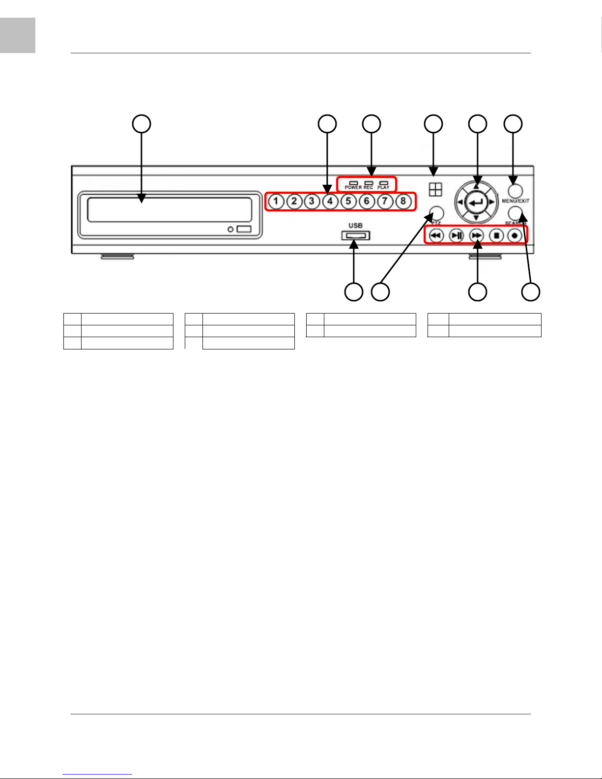
1 CD-DVD-RW* 4 IR Receiver 7 USB Port 9 Playback Controls
2 Channel Buttons 5 Navigation Control 8 PTZ Button 10 Search Button
3 LED Indicators 6 Menu/Exit Button
*CD-DVD-RW drive optional depending on model
6. MENU / EXIT BUTTON - Press the MENU key to enter the System Menu. Press the button again to
exit the System Setup or Search Menus.
7. USB - One USB 2.0 port is provided to connect a USB flash drive to the DVR.
8. PTZ BUTTON - Accesses the PTZ (Pan/Tilt/Zoom) Menu. Refer to Appendix 6 for Pan/Tilt/Zoom
options
NOTE: The PTZ option will only work with PTZ type cameras (not provided with this unit). Visit the
Lorex website at http://www.lorexcctv.com for a full range of Pan/Tilt/Zoom Cameras.
9. PLAYBACK CONTROLS - The Playback Controls have two sets of functions: Live View Functions
and Menu Functions:
• Live View Functions - Pressing the keys during Live View Mode will perform the
following functions:
o Reverse - Opens the System Information window.
o Play/Pause - Opens the Search Menu.
o Fast Forward - Sets the Live View to Sequence Mode.
o Record - Starts manual recording mode.
• Menu Functions - Pressing the keys when in the Main or Search Menus will perform
the following functions:
o Reverse - Reverses the playback of the selected Video (2x,4x,8x).
o Play/Pause - Starts or Pauses the playback of the selected video.
o Fast Forward - Fast Forwards the playback of the selected Video (2x,4x,8x).
o Stop - Stops the playback of video, and returns to the Live View screen.
o Record - Starts manual recording mode.
10. SEARCH BUTTON - Press the key to open the Search Menu
78 9 10
10
Page 11
L200 Series - Back
EN
L200 Series - Back
1 2 3 4
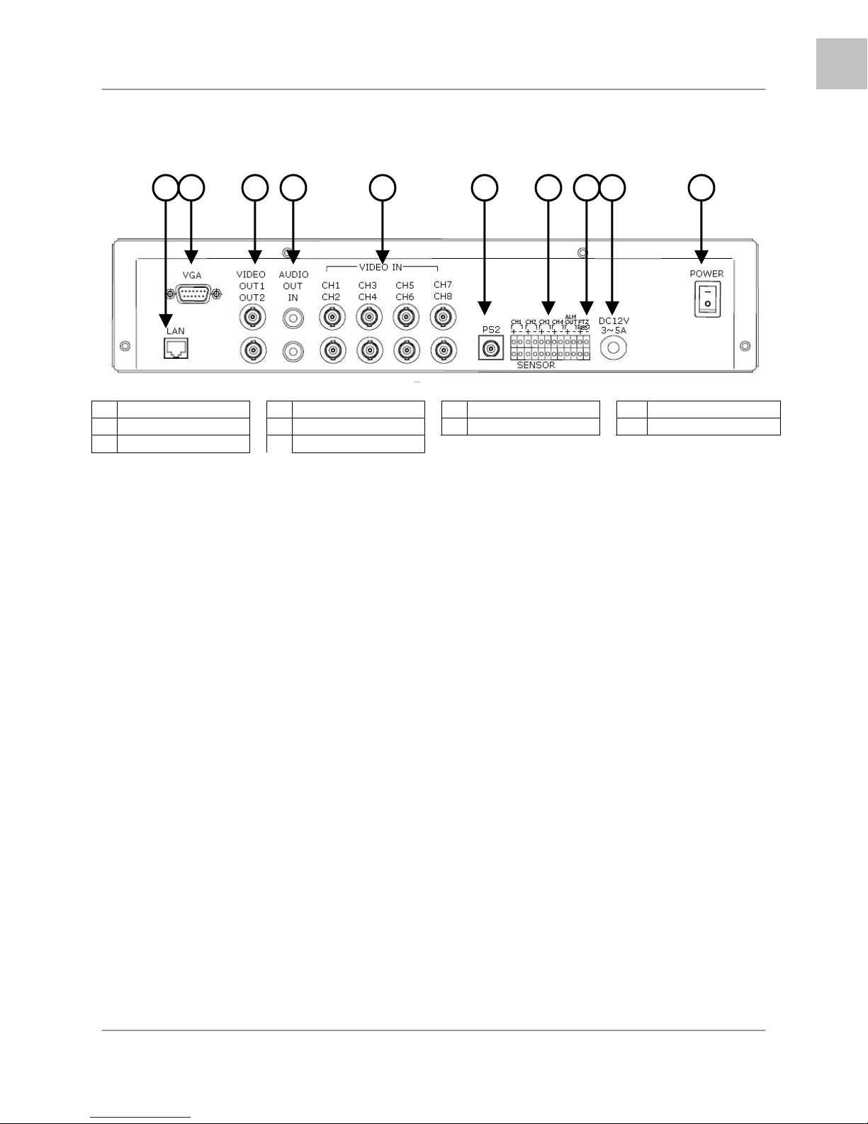
1 LAN Port 4 Audio IN/OUT 7 Alarm Block 9 Power Input
2 VGA Port 5 Video IN 8 RS-485/PTZ Block 10 Power Switch
3 Video OUT 6 PS/2 Port
1. ETHERNET CONNECTION – Connects the DVR to a router for connection to the Local Network
and Internet.
2. VGA VIDEO OUTPUT – Video Output port to connect the unit to a Computer Monitor. Directly
reflects the current onscreen images.
3. BNC VIDEO OUT (1 & 2) – Video Output ports to connect the unit to the video input of a TV or
Observation System. Directly reflects the current onscreen images.
4. RCA AUDIO OUT / IN PORTS – Connection ports for Audio:
• AUDIO OUT - Audio Output port to connect the unit to a TV or Observation System.
• AUDIO IN - Connect One Audio input device such as a microphone to record Audio on
one channel.
5. BNC VIDEO INPUTS – Channel 1~4 (L204 Series) -or- Channel 1~8 (L208 Series) camera inputs
(used to connect Cameras with BNC connection type). Cameras with BNC connections require an
additional power adapter.
6. PS/2 PORT – Connection port for a PS/2 type mouse.
7. ALARM FUNCTION TERMINALS (INPUT/OUTPUT) - These terminals are used to connect external
alarm devices such as motion sensors or door/alarm sensors. Refer to Appendix 7 for Alarm Block
Configuration.
8. RS-485 / PTZ CAMERA TERMINALS - These terminals are used to control PTZ (Pan/Tilt/Zoom)
type cameras. Refer to Appendix 6 for PTZ Configuration
9. POWER INPUT – Connect to the DVR Power using the power cord provided with the unit. The
power cable connects the DVR to an electrical outlet.
10. POWER SWITCH – Turns the DVR ON or OFF.
5 6 7 8 9 10
11
Page 12
EN
Remote Control
Remote Control
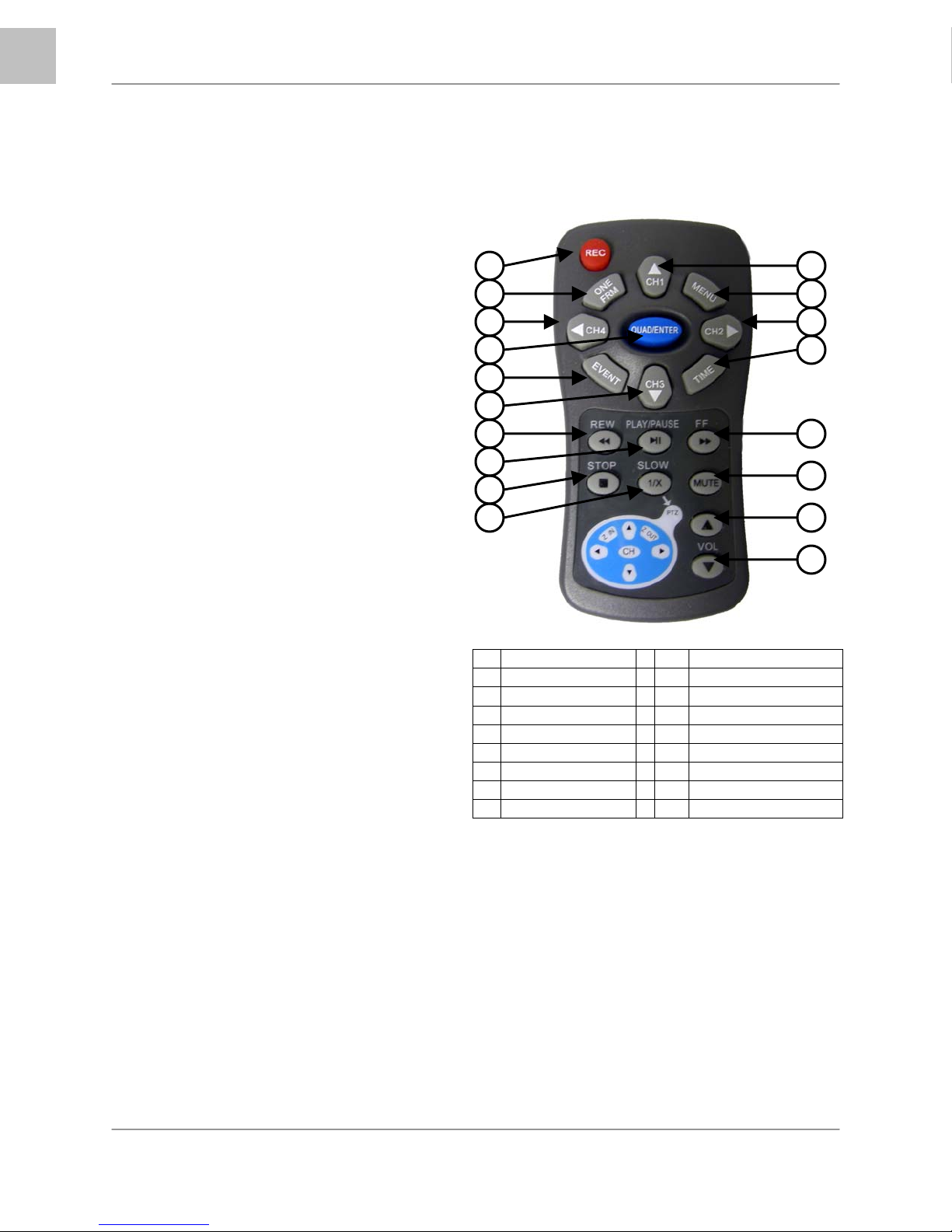
Listed below is a quick reference for the Remote Control. All Buttons described above function the same
as the Front Panel buttons.
1. REC BUTTON – Starts manual recording
on the DVR.
2. ONE FRM BUTTON – Not Used.
3. CH4 ◄ BUTTON – Press to view
QUAD2 (CH5~8 in L208 Series Only).
4. QUAD/ENTER BUTTON – Press the
ENTER Button to select and change the
values in a menu. Pressing the ENTER
Button when displaying live video will
change the onscreen view to 8 Channel
View (L208 Series Only).
5. EVENT – Not Used.
6. CH3 ▼ BUTTON – Press to switch
through the channels from CH8~CH1.
7. REV BUTTON – Opens the System
Information window (in live view mode),
and Reverses the playback of the
selected Video (2x,4x,8x).
8. PLAY/PAUSE BUTTON – Opens the
Search Menu (in live view mode), and
Starts or Pauses the playback of the
selected video.
9. STOP BUTTON – Stops the playback of
video, and returns to the Live View
screen.
10. SLOW (PTZ) BUTTON – Press to enter
PTZ View Mode (if using a PTZ Camera).
The PTZ diagram buttons correspond to
the circle of buttons on the top of the
remote.
11. CH 1 ▲ BUTTON – Press to switch
through the channels from CH1~CH8.
12. MENU BUTTON – Press the MENU key
to enter the System Menu. Press the
button again to exit the System Setup or
Search Menus.
13. CH2 ► BUTTON – Press to view
QUAD1 (CH1~4).
14. TIME BUTTON – Opens the System
Search menu (with the Backup Option
available).
15. FF BUTTON – Sets the Live View to
Sequence Mode, and increase playback
speed (2X, 4X, 8X)
16.
MUTE BUTTON – Mutes the Audio (if
using an Audio enabled Camera or
Microphone)
1
2
3
4
5
6
7
8
9
10
1 RECORD 10 PTZ MENU
2 <Not Used> 11 VIEW CH1~CH8
3 QUAD2 (CH5~8) 12 MENU / EXIT
4 ENTER 13 QUAD1 (CH1~4)
5 <Not Used> 14 SYSTEM SEARCH
6 VIEW CH8~CH1 15 FAST FORWARD
7 REVERSE 16 MUTE AUDIO
8 PLAY / PAUSE 17 VOLUME UP
9 STOP 18 VOLUME DOWN
17. VOL UP – Increases the volume of the
Audio (if in use).
18. VOL DOWN – Decreases the volume of
the Audio (if in use).
11
12
13
14
15
16
17
18
12
Page 13
Mouse Control
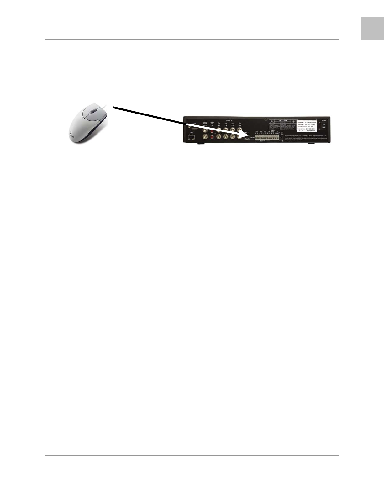
Mouse Control
A mouse can be used with this DVR for Playback and Menu controls. Connect a mouse to the
PS/2 port located on the back of the unit before powering the unit ON. Once the unit has loaded,
the mouse will be recognized by the system.
Mouse Controls
DVR Setup
• The Setup window is displayed when the right mouse button is clicked in viewing mode.
• When the mouse is moved, the purple highlight box will switch between menu options.
• Click the left mouse button to access a menu selection
• To change a setting, click the left button of mouse on the ◄ or ► icons displayed onscreen.
• Once the setting has been changed, click the right mouse button to exit the menu.
EN
Data Playback
• To use the Playback Options, first enter the System Setup menu as described above. To
playback data, navigate to either:
o Setup Æ Search or
o SetupÆSystemÆEvent List
• Click the right mouse button during playback to control the video using the icons located on the
lower left side of the screen.
• Find the desired starting date and time for backup, and press the ▲ button to select a starting
point. The playback will go to the ending point for backup, then press ▼ button to select ending
point. Select [USB] or [CD] to move start the video backup.
NOTE: Recording must be stopped prior to starting the backup.
Advanced Reservation Record using a mouse
• Recording can be set for a desired time period using a mouse. Navigate to:
o Set-upÆRecordÆRecord Schedule
• Set the desired time period and date, and click the mouse to backup data.
Viewing Screen Control
• You can change the view on the Live Viewing screen using the mouse. On the viewing screen,
double click the left mouse button on the desired channel screen to switch to full screen view.
• Double click again to return to the QUAD View Screen.
13
Page 14
EN
Camera Installation
Camera Installation
Before you install the camera*, carefully plan where and how it will be positioned, and where you will
route the cable that connects the camera to the DVR.
Installation Warnings:
• Select a location for the camera that provides a clear view of the area you want to monitor, which
is free from dust, and is not in line-of-sight to a strong light source or direct sunlight.
• Plan the cables’ route so that it is not close to power or telephone lines, transformers, microwave
ovens or other electrical equipment that could interfere with the DVR.
• Select a location for the camera that has an ambient temperature between 14°F~113°F
(-10°C~45°C)
• If you plan to install the camera in a location that has conditions not recommended in this manual,
consult with a professional installer and consider use of a separate camera cover or housing
• Before starting permanent installation, have another person hold the camera for you while you
verify its performance by observing the image on a monitor.
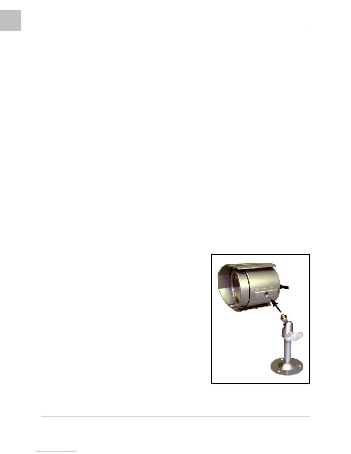
Camera Stand Installation:
1. Attach the pedestal to the ceiling, wall or other surface by the base using the provided screws.
2. The mounting bracket must be attached to a structural device such as a wall stud or ceiling rafter using
the supplied screws.
3. Attach the camera to the pedestal. Adjust the angle of the
camera, and tighten the thumbscrew to set the position
NOTE: The Camera can be attached to the stand
using the screw point on the top or the bottom (to
maintain proper camera alignment). This prevents the
image from becoming inverted.
14
* Camera may not be exactly as shown
Page 15
Connecting BNC Cameras
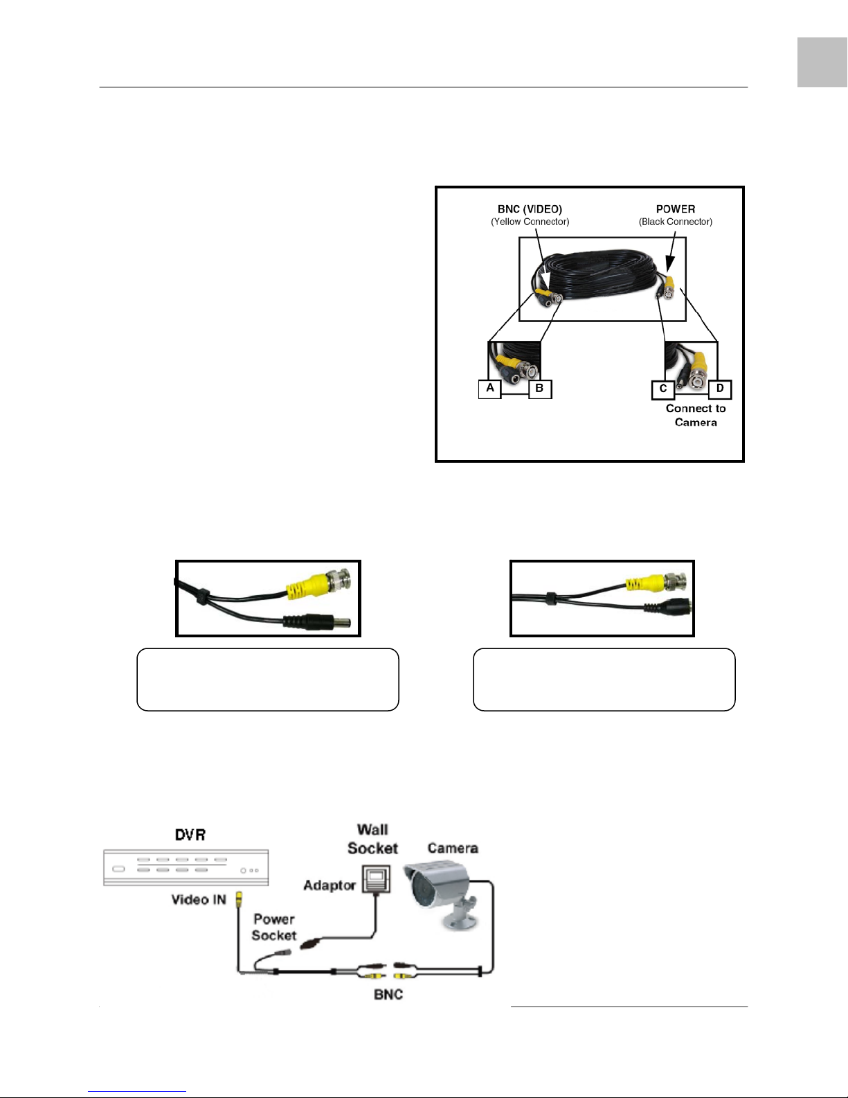
Connecting BNC Cameras
1. Connect the 60ft Extension cable to the Camera and DVR:
A. Connect the Barrel Power connector to a
power adaptor.
B. Connect the BNC connector to an available
BNC Port (CAM 1~4) on the DVR.
C. Connect the Male Power connector to the
Camera.
D. Connect the BNC connector to the Camera.
2. Connect the Power Adaptor to a wall outlet.
IMPORTANT NOTE: The ends of the extension cable are NOT the same - one end has a Male power
port, and the other has a Female power port. Before permanently running the Camera Extension Cable,
make sure that the cable has been oriented between the Camera and the unit correctly.
Male Power Port - The male power
port end of the Extension cable
connects to the Camera.
Connect to DVR and
Power Adaptor
Female Power Port - The female
power port end of the Extension cable
connects to the Power Adaptor.
EN
Camera Connection Diagram
15
Page 16
EN
Display Modes
Display Modes
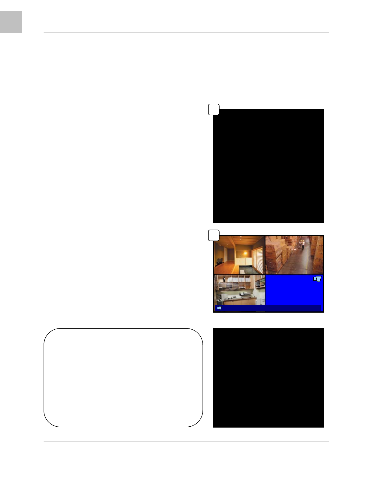
Initial Loading Sequence
The unit will automatically begin loading when power is
connected to the DVR, and the ON/OFF button on the
back of the unit is switched to ON.
1. The DVR will perform a Firmware check.
During the loading sequence, the following
information will be displayed:
• 4 or 8 Channel DVR and Firmware
Version
• Video Type: NTSC or PAL
• Disk0 Check: Displays information
about the connected Hard Drive
• Read Info: Checks previously recorded
data
• Disk1 Check: Displays information
about a second hard drive (not
available in this model).
• CD-Drive: Displays information about
the connected CD/DVD Drive.
2. The unit will initially load to a split screen view,
displaying all 4 or 8 cameras (depending on
model) with Camera Names and Recording
Status. The Drive Full, Date and Time are
displayed in the bottom bar. If a camera cannot
be displayed, a Video Loss Icon appears, and
the channel will display a blank blue screen
instead of an image.
1
8CH STANDALONE DVR LOREX
2
CH1 CH2
CH3 CH4
(FW:2.50.85 UCODE:86)
VIDEO: NTSC
DISK0: 78533MB HD7280PLAT20
READ REC INFO … DONE
DISK 1: NONE
CD DRIVE: HL-ST DVD-RAM 1.07
[STOP] TO STOP
100%4 1007/01/0 1 01:02:03
x
NOTE: If a new HARD DRIVE is detected, the
system will prompt you to FORMAT the drive. If
you do not choose to format the HARD DRIVE, the
drive will not be detected by the system.
If you choose to FORMAT a drive in this way, the
drive will no longer be readable by a regular PC.
Press the PLAY button to format the drive, or pres
the STOP button to cancel the format.
2007/10/10 01:02:03
16
V-LOSS
8CH STANDALONE DVR LOREX
(FW:2.50.85 UCODE:86)
VIDEO: NTSC
DISK0: 78533MB HD7280PLAT20
NEW DISK
DISK1: NONE
DISK0: PRESS [PLAY] FORMAT
[STOP] CANCEL
FORMAT … DONE.
CD DRIVE: HL-ST DVD-RAM 1.07
Page 17
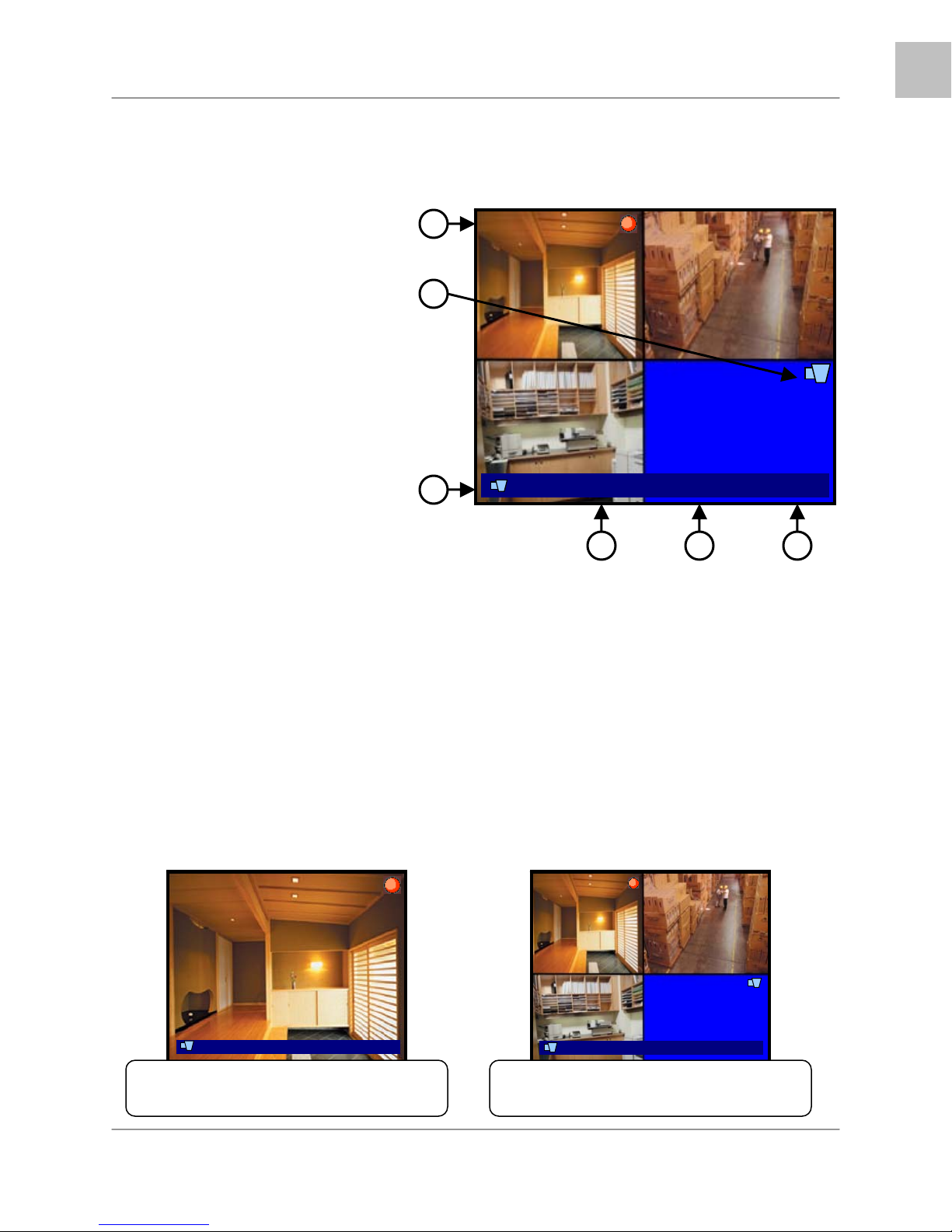
General Display Overview
1. CAMERA TITLE & RECORDING
STATUS - Displays the Camera Name
(Up to 8 Characters) and Displays the
current Recording Status (if the System
is recording the
2. VIDEO LOSS ICON - Appears when
the Camera is not sending a Video
Image.
4. DRIVE FULL INDICATOR –
Indicates the amount of drive space
available (100% indicates full). If the
circle with arrows (
DVR is in Overwrite Mode.
5. DATE - Displays the current Date for
the DVR.
6. TIME - Displays the current Time for
the DVR.
□ symbol appears).
4) is displayed the
1
2
CH1 CH2
CH3 CH4
3
100%4 1007/01/01 01:02:03
4
Display Modes
5
EN
x
5
Camera Display Modes
Cameras can be displayed in Single Channel, QUAD1, QUAD2, 8CH-Split or Sequence Modes.
• The DVR defaults to Quad view when first loaded.
• Press the Channel Buttons to display a single channel.
• Press the CH1 Button again to display QUAD1 (CH1~CH4), or press the CH5 Button again to
display QUAD2 (CH5~CH8)
• Press the FF (Fast Forward) button to display all cameras in a rotating sequence mode (3 second
view per channel by default).
CH1
SINGLE CHANNEL VIEW – Press the
corresponding Channel Number to view.
100%4 07/01/01 01:02:03
CH1 CH2
CH3 CH4
100%4 07/01/01 01:02:03
QUAD1 (CH 1~4) – Press the CH1 button
to display the Quad View.
17
Page 18
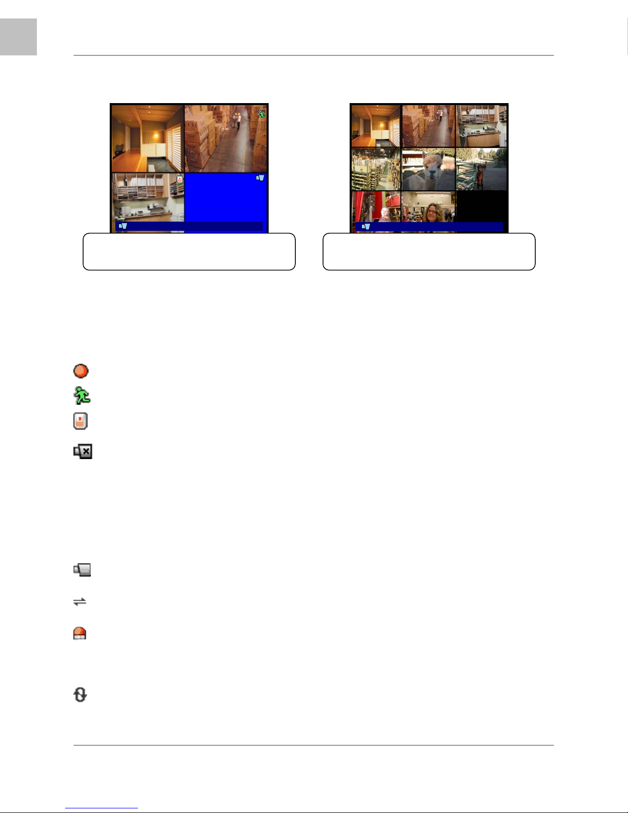
EN
Display Modes
CH5 CH6
CH1 CH2 CH3
CH7 CH8
CH4
CH7
CH5 CH6
CH8
QUAD2 (CH 5~8) – Press the CH5 button
to display the Quad View.
100%4 07/01/01 01:02:03
100%4 07/01/01 01:02:03
9-CHANNEL VIEW – Press the ENTER
Button to display all cameras (L208 Series)
Onscreen Symbols – Channel Symbols
The following symbols appear on a channel to indicate the status of the channel:
Indicates that the channel is currently Recording video.
Indicates that Motion has been detected on the channel.
Indicates that a Sensor (Alarm) has been signaled on the channel.
Indicates that there is no video signal coming from the camera.
Note: If the screen is blue and not displaying this symbol, check the camera connection.
Onscreen Symbols – Status Bar
Indicates that DVR is in monitoring mode.
Indicates that a network user is connected to the system.
Indicates that alarm on system has been activated.
% Displays the amount of space used on the Hard Drive.
Indicates that the DVR is in continuous recording mode.
Note: Data will be overwritten when the drive is full.
18
Page 19
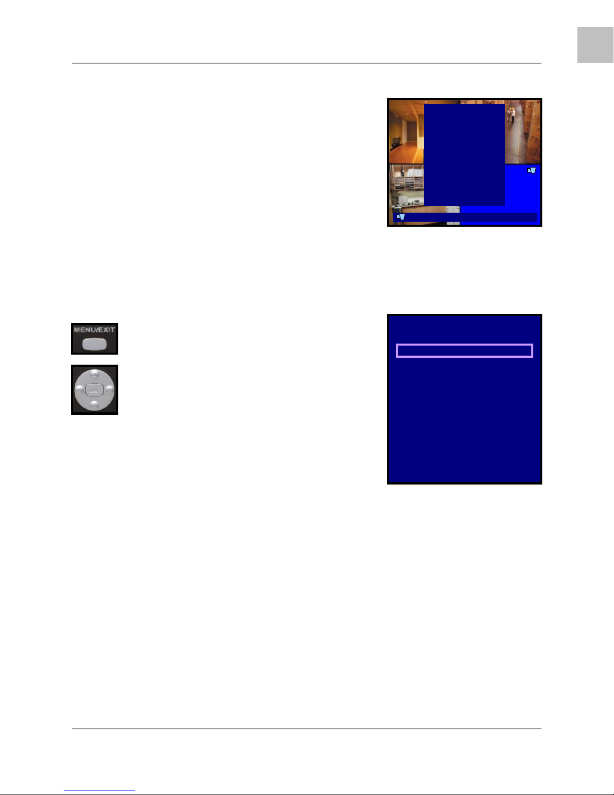
System Setup Controls
• Enter the SYSTEM MENU screen by pressing the
MENU/EXIT button. Enter the password to display the
Menu Selection Screen.
• Scroll through the 11 options by pressing the UP & DOWN
(
▲▼) buttons on the Front Panel or Remote Control.
• To enter a sub-menu, navigate to the option (indicated by
the Purple Hightlight) and press the ENTER Button ( ↵ ).
• To exit a SUBMENU, press the MENU/EXIT button.
• To change the options, press the RIGHT and LEFT buttons
(
◄►).
• To exit the MAIN MENU, press the MENU/EXIT button. If
system changes were made, a prompt will appear to Save
Changes when exiting the menu.
Menu Navigation Controls
• MENU/EXIT Button - Accesses the setup menu, and
returns to previous menu options.
• ENTER Button (↵) - Enters a Menu setting
• UP / DOWN Controls (
through the Menu Options.
• LEFT / RIGHT Controls (
to change the Menu Settings.
▲▼) - Move Up/Down
◄►) - Move Left / Right
System Setup Controls
CH1
CH3
100%4 07/01/01 01:02:03
Setup
Camera
Record
Sensor
Motion Detection
Screen
Audio
System
Search
Status
Factory Default
Exit
Setup
Camera
Record
Sensor
Motion Detection
Screen
Audio
System
Search
Status
Factory Default
Exit
EN
Setup Menu - Options
The Setup Menu has11 options:
• CAMERA – The camera menu contains the individual camera image settings.
• RECORD – This menu contains the recording settings for Scheduled recording.
• SENSOR – This menu contains the configuration settings for Sensors connected to the DVR
Alarm block.
• MOTION DETECTION – Controls the Motion Settings for each channel, including motion
detection area
• SCREEN – Contains the settings for the DVR Display and Sequence
• AUDIO – This menu controls the Audio Recording, Input and Output
• SYSTEM – Contains the System Settings, including Hard Drive, Password, Time and Date
Settings, Network, PTZ Setup and Firmware Upgrading
• SEARCH – Search the drive for previously recorded video and events
• STATUS – Displays the system settings
• FACTORY DEFAULT – Restores Factory Defaults
• EXIT – Returns to the main viewing screen
19
Page 20

EN
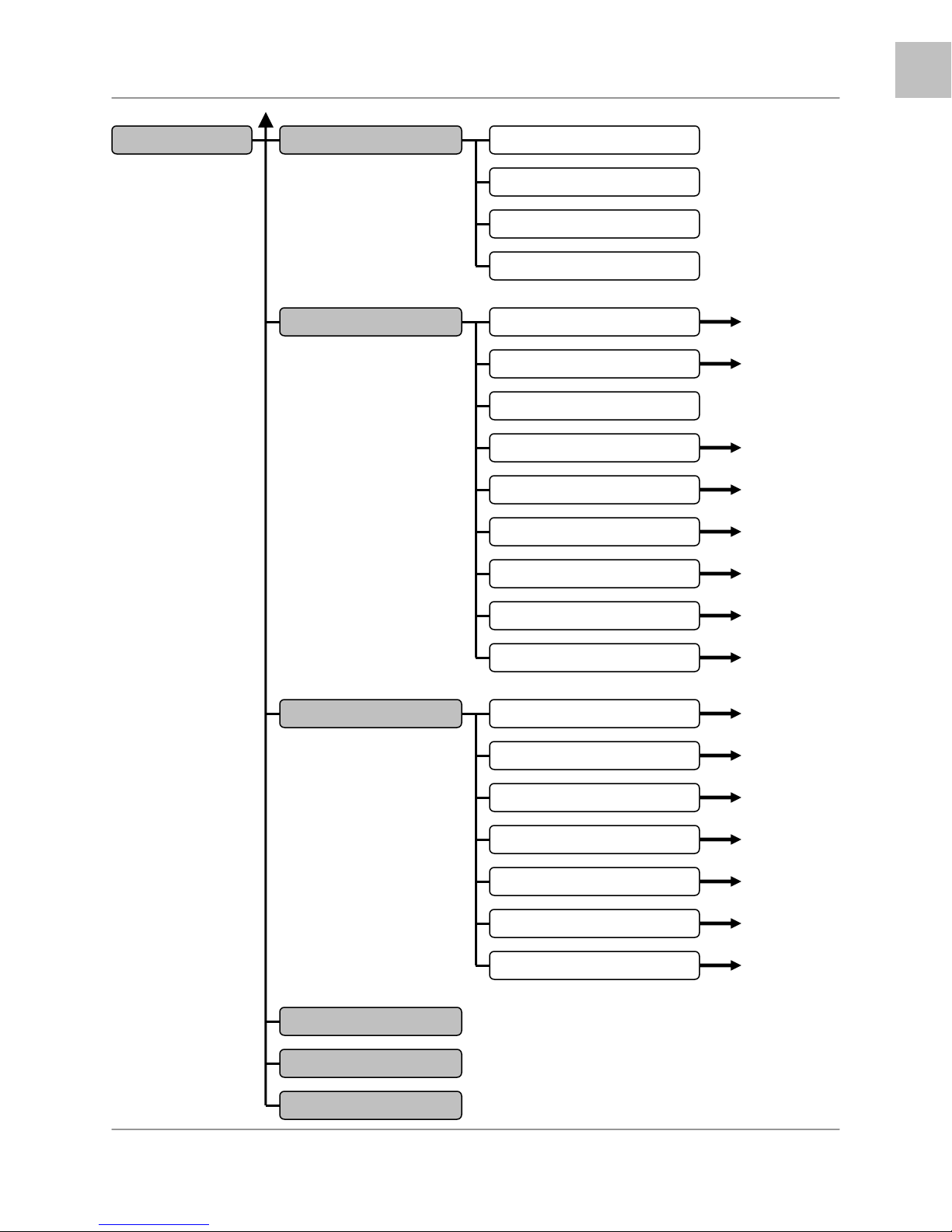
System Setup Controls
System Menu Tree
SETUP
CAMERA
RECORD
SENSOR
MOTION DETECT
SCREEN
CHANNEL
DISPLAY
BRIGHTNESS
CONTRAST
HUE
SATURATION
RECORD SPEED
RECORD QUALITY
EVENT REC DURATION
RECORD SCHEDULE
REC SCHED ENABLE
ALARM DURATION
SENSOR 1
SENSOR 2
SENSOR 3
SENSOR 4
CHANNEL
SENSITIVITY
ALARM DURATION
MOTION AREA
BOARDER
VIDEO ADJUSTMENT
SEQUENCE INTERVAL
20
Page 21
MAIN MENU
AUDIO
SYSTEM
EN
System Setup Controls
RECORD
MUTE
INPUT VOLUME
OUTPUT VOLUME
HARD DISK SETUP
PASSWORD CHANGE
PASSWORD ENABLE
TIME SET
SYSTEM EVENT LIST
NETWORK
RS-485
SEARCH
STATUS
FACTORY DEFAULT
PAN \TILT DEVICE
F/W UPGRADE
TIME SEARCH
NORMAL RECORD
TIME RECORD
MOTION RECORD
SENSOR RECORD
TOTAL RECORD EVENTS
BACKUP
EXIT
21
Page 22
EN
System Setup Controls
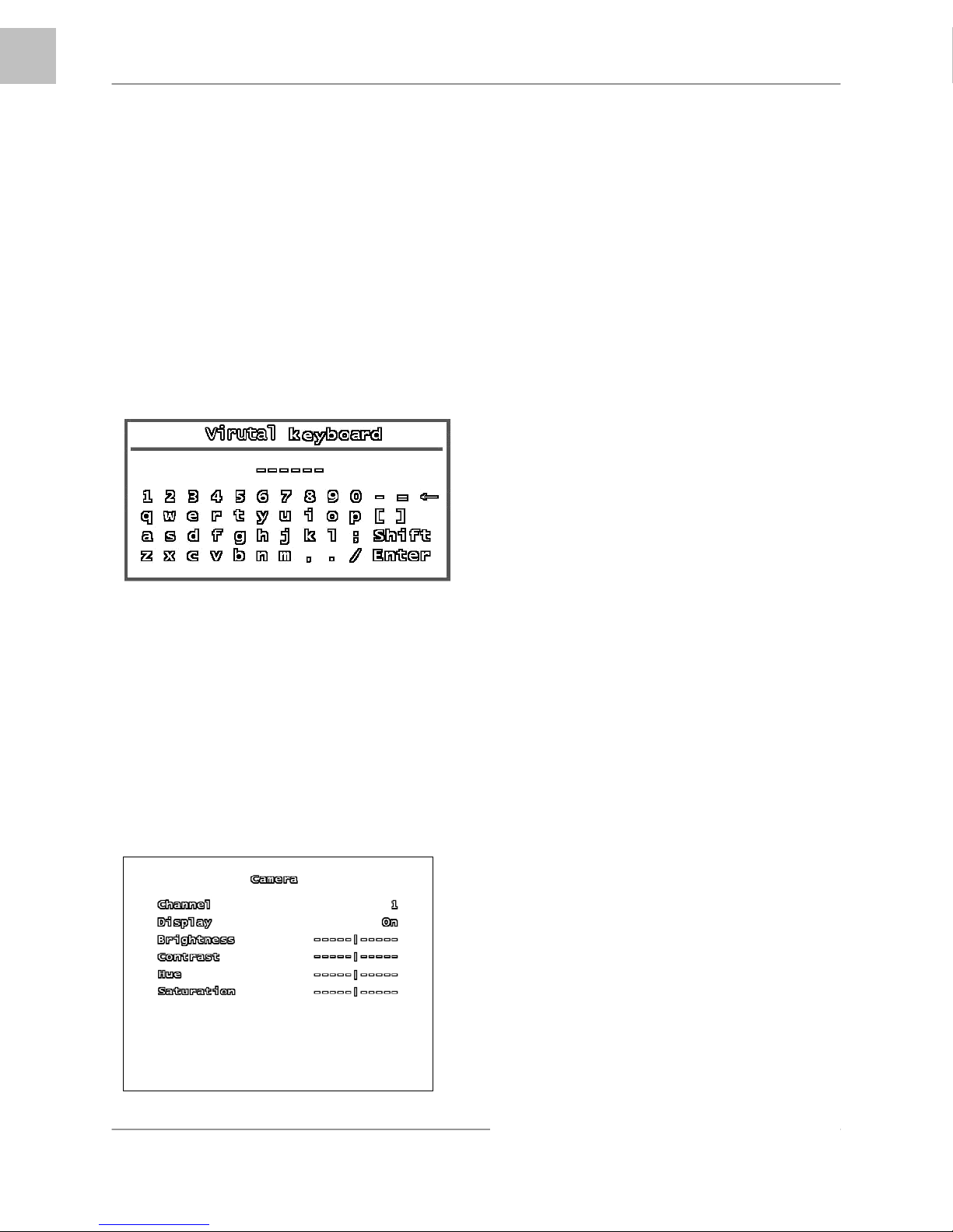
Using the Virtual Keyboard
The Virtual Keyboard control becomes
available when keyboard input is needed for
entering information such as Names, Network
Information, etc.
• Includes a~z, A~Z, 0~9 and
Symbols: !@#$%^&*()_+{}<>?-=[];,./
• Navigate using the arrow keys
▲▼◄►
Remote Control.
• Use the ENTER Button to choose the
letters, numbers and symbols
• Press the Menu/Exit button once the
setup is completed
on the Front Panel or
CHANNEL
Switch between CH1~CH4 (L204 Series) or
CH1~CH8 (L208 Series) to change the
settings for the individual channel.
DISPLAY
Set the onscreen display of the camera to ON
or OFF (Covert Camera). If the camera is in
Covert (not displayed), it will continue to
record as normal.
BRIGHTNESS
CAMERA SETUP
The CAMERA SETUP controls the display
settings for each Channel on the DVR.
Use the
settings, and the
values. Press the MENU/EXIT button to return
to the previous menu.
▲▼ arrows to navigate through the
◄► arrows to change the
Set the brightness of the image by setting the
value between 1 (darkest) to 10 (brightest).
Move the slider bar left or right to change the
brightness setting.
CONTRAST
Set the contrast of the image by setting the
value between 1 (lowest) to 10 (highest).
Move the slider bar left or right to change the
contrast setting.
HUE
Set the hue of the image by setting the value
between 1 (pale) to 10 (deep). Move the
slider bar left or right to change the hue
setting.
22
SATURATION
Adjust the color richness of the display. Move
the slider bar left or right to change the
saturation setting.
Page 23
RECORD SETUP
The Record Setup controls the settings for
Recording for the DVR.
Use the
settings, and the
values. Press the MENU/EXIT button to return
to the previous menu.
▲▼ arrows to navigate through the
◄► arrows to change the
EN
System Setup Controls
RECORD QUALITY
Set the RECORD QUALITY to LOW, NORMAL or
HIGH. This setting is the same for all channels.
• With a higher Recording Quality, the
image will appear clearer during playback;
however more storage space will be
required on the Hard Drive to save the
video.
• With a lower the Recording Quality, the
image will appear less clear during
playback; however less space storage
space will be required on the Hard Drive to
save the video.
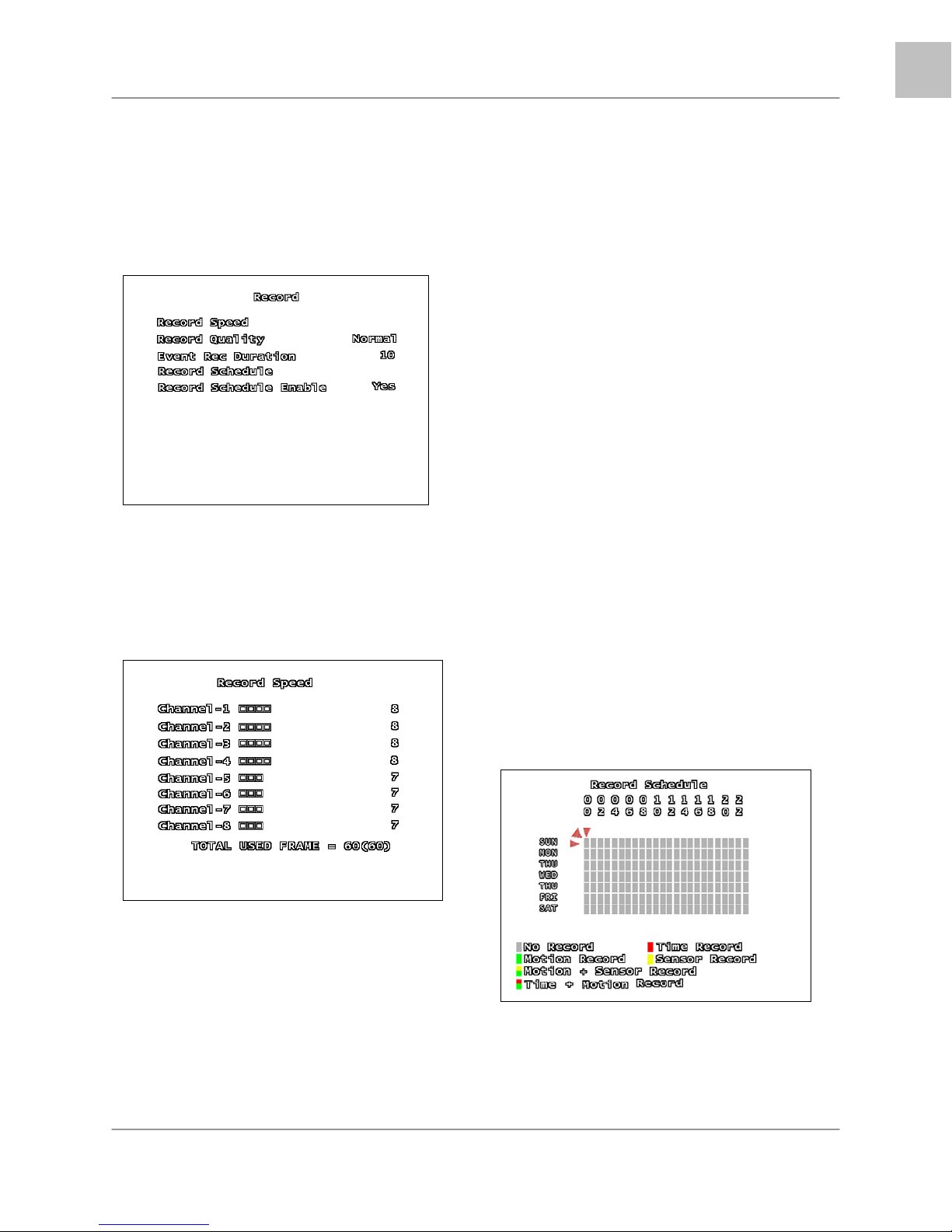
RECORD SPEED SUBMENU
The Record Speed Submenu controls the
Frames per second (FPS) used for each
channel.
(L208 Series menu shown)
The total available Frame Rate is 60 FPS.
These frames are shared across all channels,
and can be divided according to channel
importance.
For example, a camera pointed at the front
door may require a higher frame rate (i.e. 15
FPS) than a camera that is monitoring a low
traffic area (i.e. 7 FPS).
EVENT REC DURATION
Set the Recording Duration when an EVENT
(sensor / motion) is detected on the system. Set
the duration to 5, 10, 15, 20, 25 or 30 seconds.
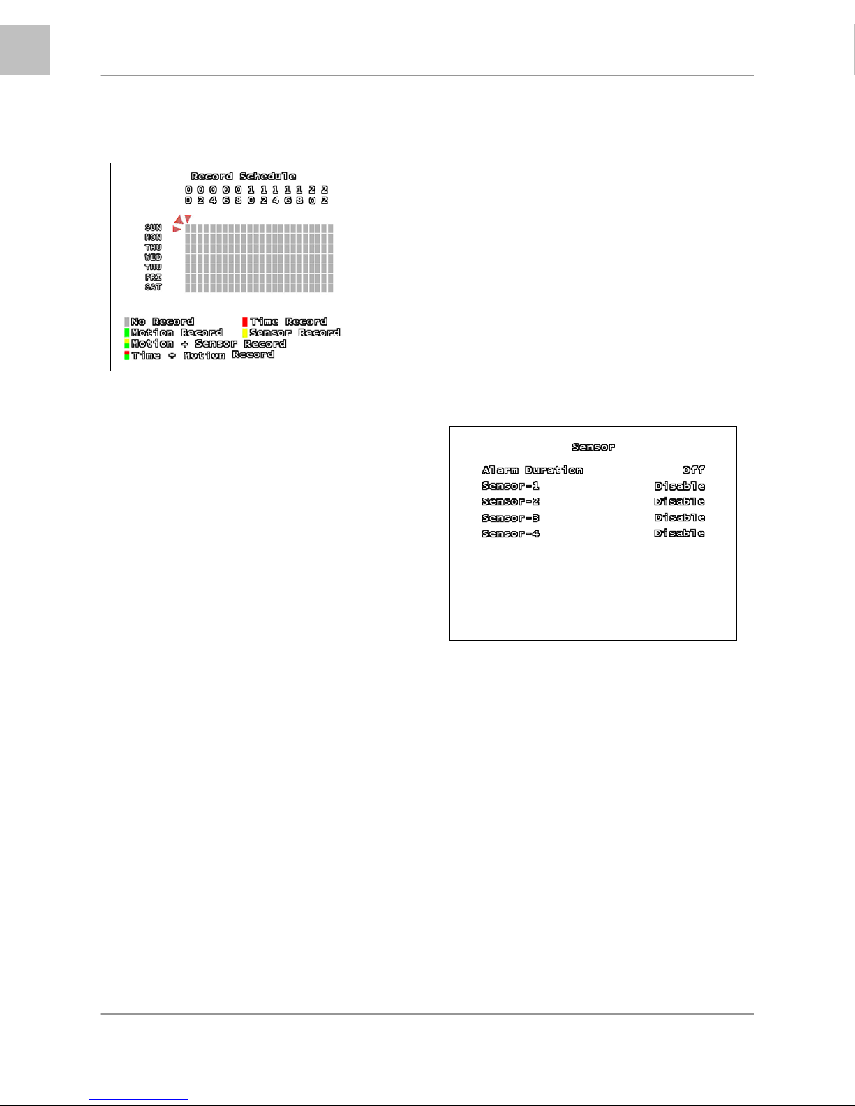
RECORD SCHEDULE SUBMENU
The Recording Schedule is based on a 24-hour
clock, and each hour can be set for a different
recording type.
23
Page 24
EN
System Setup Controls
RECORD SCHEDULE
Move cursor to the desired time using the
▲▼◄► arrows, and press the ENTER
Button to scroll through the available recording
settings:
• No Record – The System will not
record video during this period.
• Time Record – The System will record
data continuously during this period.
• Motion Record – The System will
record data only when the camera
recognizes motion in a designated area
during this period.
• Sensor Record – The System will
record data only when an sensor or
alarm is signaled during this period.
• Motion + Sensor Record – The
System will record data when either
Motion or a Sensor/Alarm is detected.
• Time + Motion Record – The System
will continuously record data during this
period. If motion is detected during this
time, the video will be flagged in the
system as a Motion Event.
• To set the entire line (all hours in a
day) to the same recording type, set
one square in the day to the desired
recording type. Remain on that square,
and press the Record
• To set all days to the same recording
type, use the mouse to set the top left
corner (Sun 0hr) to the desired
recording type, and click on the red
diagonal arrow (to the upper left of the
square).
• Button.
RECORD SCHEDULE ENABLE
Sets the Recording Schedule to ON or OFF.
NOTE: It is important to leave this setting to
ON. If this setting is turned OFF, the DVR will
NOT record any data (Manual Recording
(when the REC Button is pressed) will override
the Record Settings, and immediately begin
recording.)
SENSOR SETUP
ALARM DURATION
Determines how long an alarm lasts after
detection. Settings include: OFF, 05, 10, 15,
20, 25, 30 Seconds or CONT (continuously).
If there are no sensors connected to the DVR,
set the Alarm Duration to OFF.
SENSOR - 1, 2, 3, 4
Set the type of sensor installed for CH1~CH4.
The settings include: DISABLE (none),
Normally Open (NO) or Normally Closed (NC).
24
Page 25
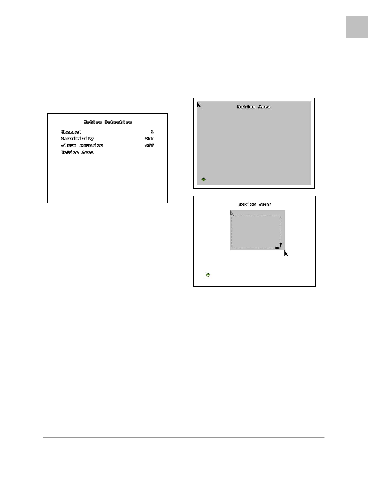
MOTION DETECTION SETUP
The Motion Detection Setup controls the
behavior of the DVR when Motion is detected.
Use the
settings, and the
values. Press the MENU/EXIT button to return
to the previous menu.
▲▼ arrows to navigate through the
◄► arrows to change the
EN
System Setup Controls
MOTION AREA SUBMENU
Use the Motion Detection area to determine
which areas of the image will detect motion.
Areas shaded with a darker color indicate that
the area is selected to detect motion.
CHANNEL
Switch between CH1~CH4 (L204 Series) or
CH1~CH8 (L208 Series) to change the
settings for the individual channel.
SENSITIVITY
This setting adjusts the sensitivity of the pixel
based motion detection on the DVR. Set the
option from 1 (low sensitivity) to 4 (high
sensitivity) or OFF.
ALARM DURATION
Determines how long an alarm lasts after
detection. Settings include: OFF, 05, 10, 15,
20, 25, 30 Seconds or CONT (continuously).
If there are no sensors connected to the DVR,
set the Alarm Duration to OFF.
Using the Front Panel Buttons:
1. Use the front panel arrows ▲▼◄► to
navigate to the desired starting location.
2. Press the Enter button once. Use the arrows
to drag the block to the desired area coverage.
3. Press the Enter button to stop setting the
motion area.
NOTE: Only one blocked section can be set on
the Detection Area. Multiple selections cannot
be added.
Using a Mouse:
1. Press and hold the left mouse button
2. Drag to select the detection area
NOTE: Click the arrow icon to set the entire
area for motion detection.
25
Page 26
EN
System Setup Controls
SCREEN SETUP
The Screen Setup controls the onscreen
display of the DVR.
Use the
settings, and the
values. Press the MENU/EXIT button to return
to the previous menu.
▲▼ arrows to navigate through the
◄► arrows to change the
AUDIO SETUP
The Audio Setup adjusts the Audio
input/output of the DVR system.
Use the ▲▼ arrows to navigate through the
settings, and the ◄► arrows to change the
values. Press the MENU/EXIT button to return
to the previous menu.
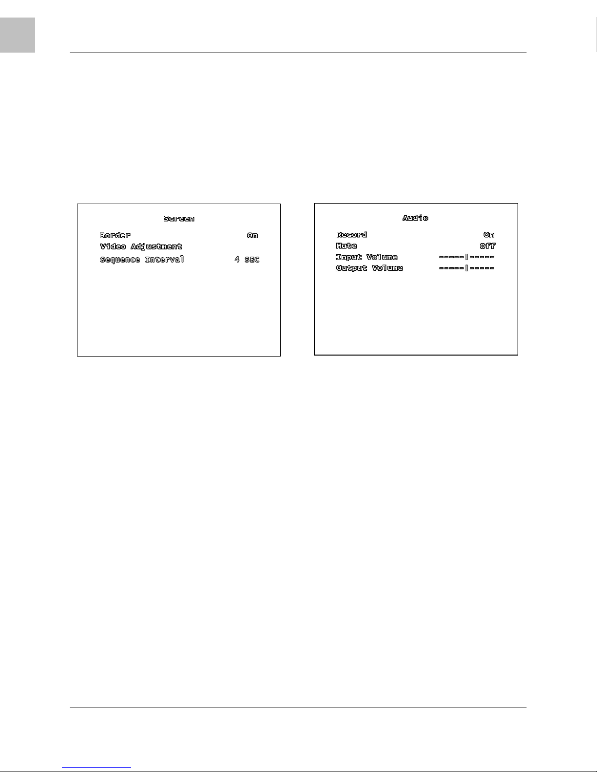
BORDER
The border is the white line that appears
around each channel. Set the option to ON
(displays the border) or OFF (no border).
VIDEO ADJUSTMENT SUBMENU
Use the Video Adjustment to change the
position of the entire screen, using the
▲▼◄► arrow keys.
SEQUENCE INTERVAL
Set the length of time that each channel will
be displayed in full screen during Sequence
Mode. The sequence interval can be set
between 0 seconds to 7 seconds.
NOTE: Press the FF Button on the front panel
to enter Sequence Mode when viewing live
video.
RECORD
Set Record to ON to enable sound recording
(when a microphone is attached into the
AUDIO INPUT port on the system).
NOTE: The audio is shared across the entire
system, and cannot be set for a specific
channel (i.e. if an audio device is connected
near Channel 4, the same audio will be
recorded on all channels).
MUTE
Set the system mute ON or OFF.
INPUT/OUTPUT VOLUME
Adjust input and output volume levels. Move
the slider bar left (low volume) or right (high
volume) to change the volume setting.
26
Page 27
System Setup Controls
EN
SYSTEM MENU
The System Setup controls many aspects of
the functionality in the DVR, including the
Password, Time and Date, Network and PTZ
setup.
Use the
settings, and the
values. Press the ENTER button to enter a
submenu, and press the MENU/EXIT button to
return to the previous menu.
▲▼ arrows to navigate through the
◄► arrows to change the
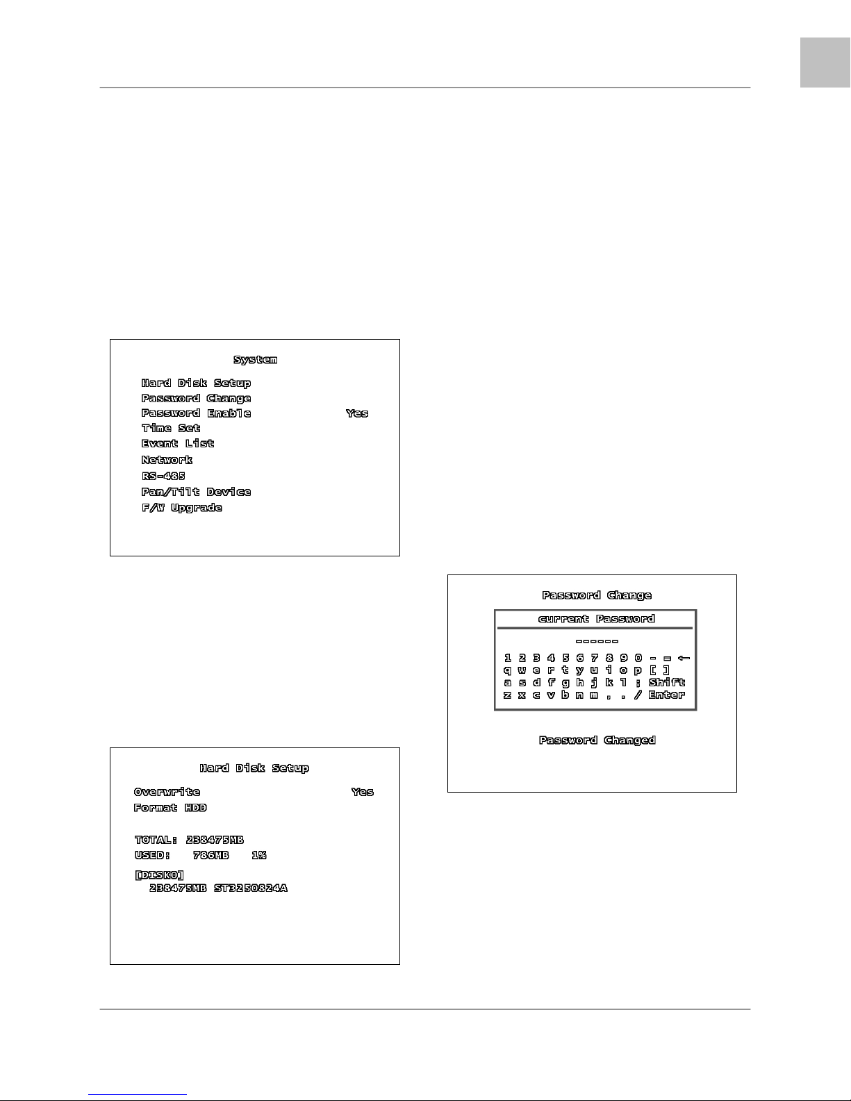
OVERWRITE – If the Overwrite option is set to
Yes, when the Hard Drive becomes full the
system will begin overwriting the older
information. If Overwrite is set to No, then the
DVR will stop recording when the Hard Drive
becomes full.
FORMAT HDD – Formatting the Hard Drive
erases all stored video data (firmware settings
are not erased). When you choose to Format
the drive, the system will prompt you for the
password before formatting (The default
password is [111111] ).
NOTE: Once the drive has been formatted, you
will no longer have access to the previously
recorded data, and there is no recovery.
PASSWORD CHANGE SUBMENU
The Password Change submenu allows the
user to change the system password.
HARD DISK SETUP SUBMENU
The Hard Disk Setup contains information
about the installed Hard Drive (Total Hard
Drive Space, and Space Used), and allows the
user to Set the Overwrite and Format the drive.
Any combination of buttons on the front panel
of the DVR can be used in the new password.
Enter the new characters, and press the Enter
button to finish.
A Password Changed message will be shown
on screen when the password is successfully
changed in the system.
27
Page 28
EN
System Setup Controls
PASSWORD ENABLE
The Password Enable feature turns the use of
a system password ON or OFF. If the option is
set to YES, the password is required when
entering the Setup Menu, Resetting Factory
Defaults, Using the PTZ and Stopping video
recording.
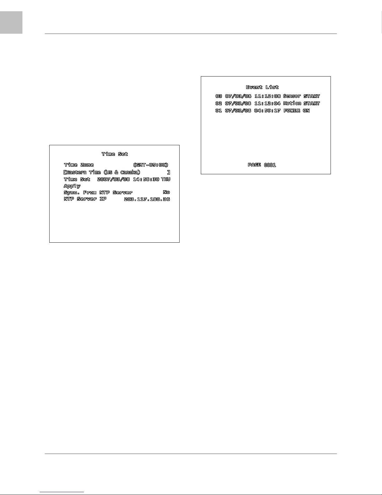
TIME SET SUBMENU
The Time Set menu controls the date and time
for the DVR.
• TIME ZONE – Set the current time
zone by scrolling through available
options (GMT based timezones).
• TIME SET – Use the arrows to adjust
the Date and Time (YYYY/MM/DD
HH:MM:SS). Press the Menu/Exit
button to finish changing the settings.
• APPLY – Select the Apply option and
press the ENTER button to save the
changes to the date and time.
• SYNC. FROM NTP SERVER –
Synchronizes the system with a
Network Time Server (over the
Internet ) to set the date and time. An
internet connection is required.
• NTP SERVER IP – Enter the IP
address of the Time Server. The
default value time server IP is
203.117.180.36.
SYSTEM EVENT LIST SUBMENU
The Event List provides a detailed listing of the
events that have occurred in the system.
>
The Event List includes:
• DVR Power ON / OFF
• Recording Start / Stop
• Sensor ON / OFF
• Motion Detection
• Timed Recording Start / Stop
The list is displayed by Event Number, Date,
Time and Event type.
Navigate through the events using the arrow
buttons.
To Playback a valid event, select the event
from the list and press the ENTER button.
SYSTEM MENU
BUZZER ALARM TIME
LOSS ALARM
AUDIO RECORD
AUDIO MUTE
AUDIO INPUT VOL.
AUDIO OUTPUT VOL.
PASSWORD SETUP
TIME SETUP
28
Page 29
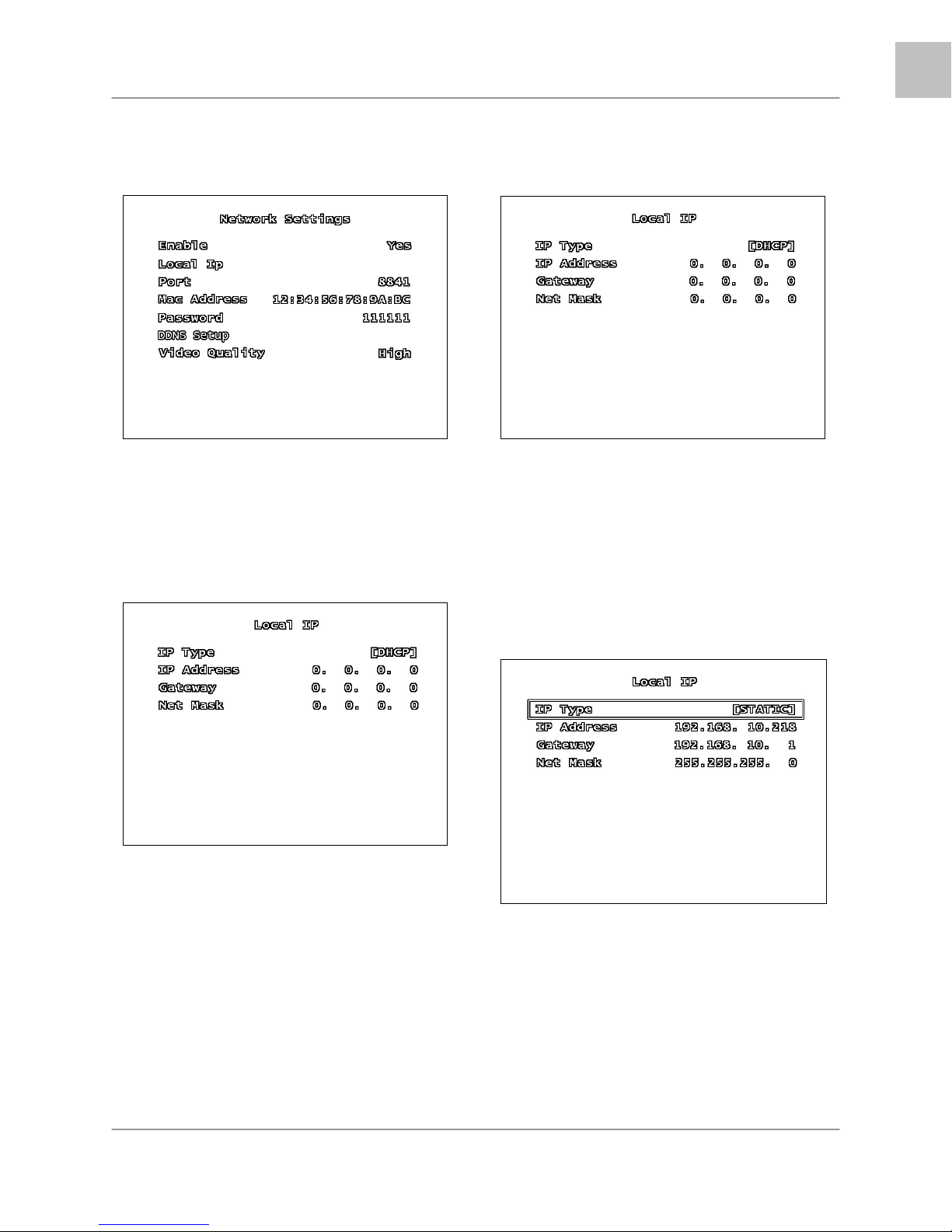
NETWORK SUBMENU
The information in the Network submenu
allows users to remotely access the DVR.
EN
System Setup Controls
DHCP SETUP
ENABLE – Set Enable to YES to remotely
connect to the DVR over a network connection.
If this option is set to NO, remote access to the
system will be disabled.
LOCAL IP MENU – The Local IP menu
contains the IP Address and other networking
information.
• IP TYPE – The IP Type determines
how the Network Information is entered
into the DVR. There are three network
connection types:
o DHCP – The network
automatically leases the
information to the DVR
o Static – Enter the information
manually based on the
connected network
NOTE: The Local Network will lease the
information to the DVR. The user is not
required to complete these fields.
• IP Type: DHCP
• The information for the IP Address,
Gateway and Net Mask will be
automatically provided by the Local
Area Network.
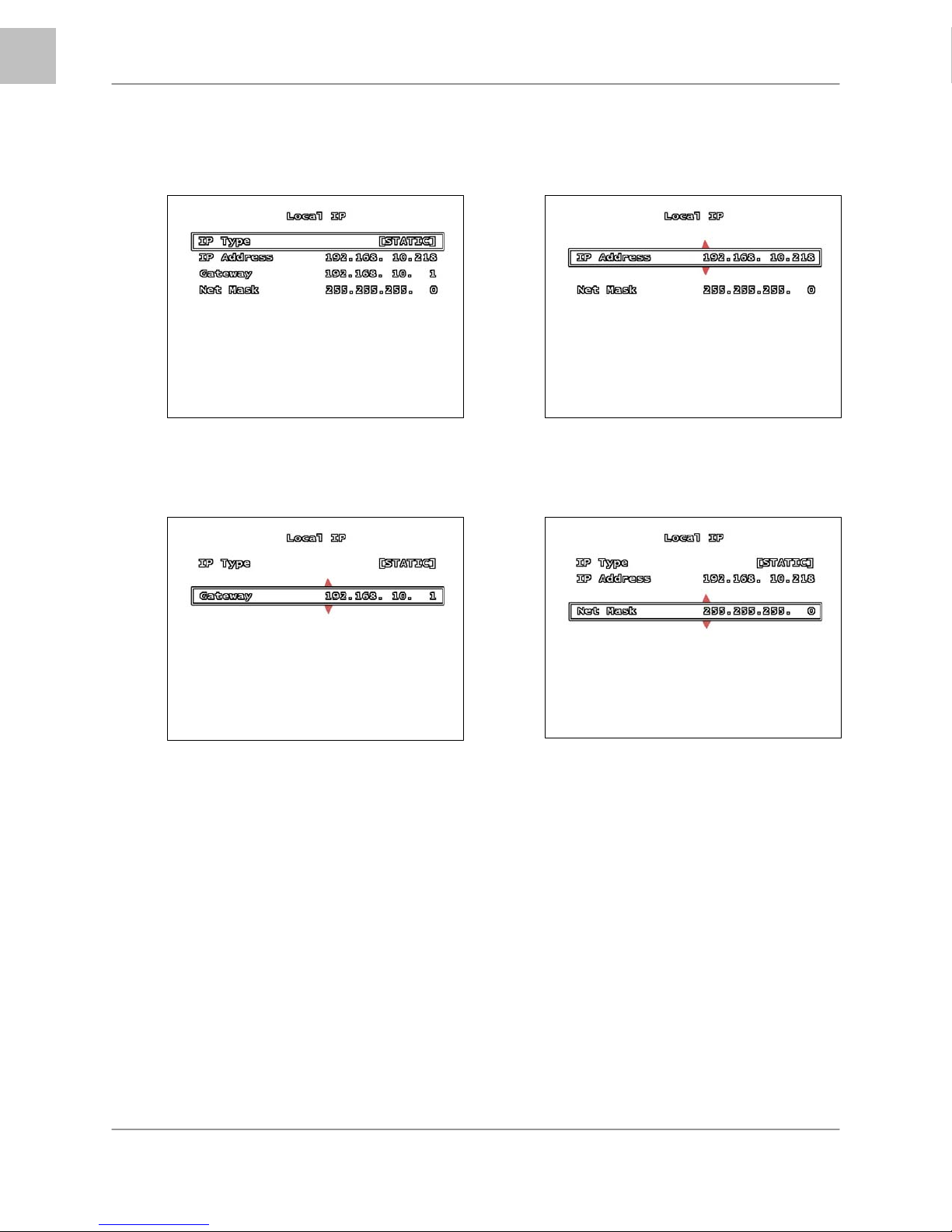
STATIC SETUP
NOTE: Gather the Network Information from
the Network Router prior to changing these
settings.
• IP Type: Static
• IP Address: Enter an IP address that
is not currently in use on the local
network.
• Gateway: Enter the Gateway for the
local network.
• Net Mask: Enter the Subnet Mask
information for the local network.
29
Page 30
EN
System Setup Controls
STATIC SETUP
Use the arrow buttons to change the Network Settings:
1 2
3 4
30
Page 31

NETWORK SUBMENU (CONT.)
EN
System Setup Controls
DDNS SETUP
PORT – The Port Information is required for
remote access. The default port for the DVR is
8841. Please refer to the Port Forwarding
section of this manual for details.
MAC ADDRESS – The Mac Address is the
unique physical address set by manufacturer,
which is necessary for DDNS network
connection. Do not change this value.
PASSWORD – A Password is required for
network connection. Set the password using
the buttons on the front panel.
DDNS SETUP MENU – The DDNS Setup
menu contains the configuration settings for
remote access via the Lorex DDNS Service
(http://ddns.strategicvista.net
).
A DDNS Service updates the remote
connection information, and is useful when the
IP Address frequently changes.
• Enable: Set to YES if using the DDNS
Service. DDNS ID: DDNS SERVER
SET-UP (ENABLE): Select “YES” in
name server set-up.
• DDNS ID: Enter the name from the
DDNS Registration using the virtual
keypad. Press ENTER once complete.
• DDNS PASSWORD: Enter the
password from the DDNS Registration
using the virtual keypad. Press ENTER
once complete.
• DOMAIN NAME: Enter the domain
name from the DDNS Registration
using the virtual keypad. Press ENTER
once complete.
NOTE: Do not enter the entire DDNS address
(i.e. myurl.strategicvista.net) – only the first part
of the address should be entered (i.e. myurl
from the example above).
• STATUS: Displays the status of the
DDNS Connection. A Success
message indicates that the network
connection has been established.
31
Page 32

EN
System Setup Controls
RS-485 SUBMENU
The information in the RS-485 submenu allows
users to configure the settings for an RS-485
Device.
NOTE: The configuration settings for this
section would be provided with the
documentation included with the RS-485
device.
• BAUDRATE: Set the Data
Transmission (Baud rate) to1200,
1800, 2400, 4800, 9600, 14400,
19200, 36400, 57600 or 115200 bps.
• DATA BIT: Set the Data Transmission
Bit to 7 or 8.
• PARITY BIT: Set the Data
Transmission Error Check Bit to odd,
even or none.
• STOP BIT: Set the Data Transmission
Stop Bit to 1 or 2.
PAN/TILT DEVICE SUBMENU
NOTE: The configuration settings for this
section would be provided with the
documentation included with the PTZ Camera.
• CHANNEL: Select the Channel where
PTZ camera is connected.
• ID: Assign the specific ID of the PTZ
camera.
• MODEL: Select the model of PTZ
camera.
• PAN/TILT TEST: Test PTZ Camera.
F/W UPGRADE
The DVR supports upgrading the Firmware
through a USB Memory Stick.
If a USB Memory Stick is not detected by the
system, a failure message will appear:
If a USB Memory Stick is detected with valid
Firmware files, the following screen will appear:
PAN/TILT DEVICE SUBMENU
The information in the PAN/TILT Device
submenu allows users to configure the settings
for a PTZ Camera.
32
Press the PLAY Button to update the firmware,
or press the STOP Button to cancel.
Page 33

SEARCH MENU
The Search Menu contains a list of submenus
to search through previously recorded video.
Use the
settings, and the
values. Press the MENU/EXIT button to return
to the previous menu.
▲▼ arrows to navigate through the
◄► arrows to change the
EN
System Setup Controls
STATUS MENU
The Status Menu Displays the System
Information. Pressing the REV key will also
display the Status Window.
• TIME SEARCH: Searches for video
based on Time and Date.
• NORMAL RECORD EVENT: Searches
for video that was recorded manually
(using the REC button).
• TIME RECORD EVENT: Searches for
video that was recorded on a schedule.
• MOTION RECORD EVENT: Searches
for video that was recorded when
motion was detected.
• SENSOR RECORD EVENT: Searches
for video that was recorded during a
sensor event.
• TOTAL RECORD EVENT: Displays all
recorded video.
• BACKUP: Allows the user to back up
data to a USB Memory Stick.
FACTORY DEFAULT MENU
Choosing the Factory Default option
reinitializes the menu configuration in the
system.
NOTE: Video data is not erased when a
Factory Reset is performed.
EXIT MENU
• EXIT & SAVE CHANGES: Saves all
changes made, and exits the Menu.
• EXIT & DISCARD CHANGES: Exits
the menu without saving any changes.
NOTE: If the menu times out and returns the
user to the live viewing screen, any changes
made to the Menu will not be saved.
33
Page 34

EN
System Setup Controls
RECORDING
When a Channel is displaying a
indicates that the channel is in record mode.
In the above example, CH1~CH7 are in record
mode, and CH8 is showing a Video Loss
symbol.
Additional onscreen Information includes the
HDD Space, Date and Time.
NOTE: If the Date/Time is incorrect, please see
the Menu settings to set the correct
information.
There are several options for recording:
• No Record
• Time Record
• Motion Record
• Sensor Record
• Motion + Sensor Record
• Time + Motion Record
symbol, it
Recording Schedule Symbols:
White (No Recording)
Red (Continuous Recording): The DVR is
constantly recording, and does not detect
Motion or Sensor events.
Green (Motion Detection Recording):
Begins recording when Motion is detected, and
does not record continuously or when a sensor
event occurs.
Yellow (Sensor Recording): Begins
recording when a Sensor is activated, and
does not record continuously or when a motion
event occurs.
Green & Yellow (Motion & Sensor
Recording): Begins recording when a Sensor is
activated or when Motion is detected. The DVR
will not record continuously under this setting.
Red & Green (Continuous & Motion
Recording): The DVR is constantly recording.
When the cameras recognize motion, an event
is written to the Event List.
Using the mouse lets the user set the schedule
quickly. Set one block in the Hour or Day, and
then click the corresponding top/side arrow to
set the entire line to the same recording type.
34
Page 35

SEARCH FUNCTION
There are several ways to access the Search
Function:
• From the Main Menu / Search Menu
• Pressing the PLAY Button
• Pressing the SEARCH Button
However, each Search menu contains different
search options:
Main Menu / SEARCH Button Menu
EN
SEARCH FUNCTION
Time Search
PLAY Button Menu
• Start: Displays the Date and Time for
the first available recording.
• End: Displays the Date and Time of the
last recording.
Press the Enter Button To set the Date and
Time. Use the arrows ▲▼◄► to set the
desired Date and Time, and press the
Menu/Exit Button to accept.
Once the Date and Time are entered, navigate
to the Search option, and press the Enter
button. The video will start playing starting from
the specified time.
Press the Stop Button to end the playback.
Time Search
The Time Search option allows the user to
search for Video by entering the Date and Time
for the desired data.
35
Page 36

EN
SEARCH TYPES
SEARCH TYPES
• TIME SEARCH: Searches for video
based on Time and Date.
• NORMAL RECORD EVENT: Searches
for video that was recorded manually
(using the REC button).
• TIME RECORD EVENT: Searches for
video that was recorded on a schedule.
• MOTION RECORD EVENT: Searches
for video that was recorded when
motion was detected.
• SENSOR RECORD EVENT: Searches
for video that was recorded during a
sensor event.
• TOTAL RECORD EVENT: Displays all
recorded video.
• BACKUP: Allows the user to back up
data to a USB Memory Stick.
RECORD EVENT LISTS
The Record Event Lists display all Events of a
specific type (as described in the Search Types
section):
• Event Number: The Event Number is
listed on the Left of the listing. Up to
100,000 events can be displayed on
9999 pages
• Date & Time: Displays the date and
time of the event
• Event Type: Lists the type of event
recording (Normal, Motion, Sensor or
Time Recording)
• Up / Down Arrows: Use the mouse to
switch between events
• Page Number & Left / Right Arrows:
Switch between pages.
36
Page 37

VIDEO PLAYBACK
EN
VIDEO PLAYBACK
BACKUP FUNCTION
There are two methods to backup video data:
• To a USB flash drive
• To a Blank CD
The L200 Series DVR can play previously
recorded video onscreen, while still recording
live video images.
BUTTON DESCRIPTION
PLAY /
PAUSE
REC Start manually recording / Stop
FF Fast Forward the video playback.
REW Reverses the video playback.
STOP Stops the playback, and returns
NOTE: A detailed Button description can be
found in the Front Panel section of this
manual.
The video playback can be displayed in Single
(Full Screen) or QUAD. To change the
onscreen display, press the CH1~CH4 buttons
(L204 Series) or the CH1~CH8 buttons to
change the view.
Playback of previously recorded
data / Pauses the data playback
recording
Press the FF button to change
playback speed to 2x, 4x or 8x
speed.
Press the REW button to change
playback speed to 2x, 4x or 8x
speed.
to live monitoring mode.
NOTE: This DVR does not support video
backup when live recording is occurring.
Recording must be stopped before data
backup can be performed.
USB MEMORY STICK BACKUP
To save video to the USB Memory Stick, the
start and end times for the selection must be
set:
• Press the ▲▼ buttons to set the
backup starting and ending points
• The Available Disk Space and copy
size are shown in KB
• Press the SEARCH button to start the
backup.
NOTE: It is recommended that the size of the
USB Memory Stick is compared against the
Copy Size before starting Backup. If the drive
space is too small, the message “CAPACITY
IS NOT ENOUGH” will appear.
The Date and Time of the video image are
displayed on the lower part of the screen. The
Video Playback speed is also displayed.
37
Page 38

EN
BACK-UP VIA CD-R/W* (OPTIONAL)
BACK-UP VIA CD-R/W* (OPTIONAL)
To save video to the CD-RW, set the start and
end times for the selection:
• Press the ▲▼ buttons to set the
backup starting and ending points
• The Available Disk Space and copy
size are shown in KB
• Press the SEARCH or REC button to
start the backup.
If the data size is larger than 600 MB, the
message “DATA SIZE IS BIG TO COPY” is
displayed onscreen.
Use the ▲▼◄► Arrow keys and Enter Button
to change the Starting and Ending Date and
Time. Use the Menu button to Exit the
changes.
Once the total size of the data has been
displayed, use the arrows to select the Backup
Type (Backup to USB or Backup to CD) and
press ENTER.
USING THE BACK-UP FUNCTION
• Start / End: Use the arrows to select
the desired Start and End times for the
backup.
• TOTAL: Displays the date of the first
and last recorded video on the DVR.
• BACKUP: Indicates the desired start
and end times for the data.
• Size: Indicates the total size of the
desired data.
Once a backup type has been selected, the
DVR will copy the information to the USB flash
drive or CD.
*CD/DVD-RW optional. Hardware configuration
varies by model.
38
Page 39

EN
FIRMWARE UPGRADE
FIRMWARE UPGRADE
The DVR supports upgrading the Firmware
through a USB Memory Stick.
1. Download the new firmware from
http://www.lorexcctv.com
2. Copy the firmware files to a USB
Memory Stick.
3. Insert the Memory Stick into a USB
Port on the DVR.
4. Navigate through the System Menu:
SETUP Menu => SYSTEM Menu =>
F/W UPGRADE.
NOTE: If a USB Memory Stick is not detected
by the system, a failure message will appear:
to the PC.
NOTE: If the system is actively recording, the
Firmware Upgrade cannot take place. If
recording is in progress, press the STOP
button to end the recording before proceeding
with the firmware upgrade.
The message FIRMWARE UPLOADING... will
appear during the upgrade process. Once the
upgrade is completed, the system will reboot.
If the USB Memory Stick is detected with valid
Firmware files, the following screen will appear
displaying the Current Firmware Version and
the New Firmware Version:
Press the PLAY Button to update the firmware,
or press the STOP Button to cancel.
After the system has rebooted, the initial
loading screen displays the new firmware
version.
NOTE: Once the system has started the
Firmware Upgrade, DO NOT remove the USB
Memory Stick until after the system has
rebooted and reloaded to the Live Monitoring
screen.
To confirm that the Firmware has been
upgraded successfully, check the new version
on the loading screen.
8CH STANDALONE DVR LOREX
(FW:2.50.85 UCODE:86)
VIDEO: NTSC
DISK0: 78533MB HD7280PLAT20
NEW DISK
DISK1: NONE
DISK0: PRESS [PLAY] FORMAT
[STOP] CANCEL
FORMAT … DONE.
CD DRIVE: HL-ST DVD-RAM 1.07
39
Page 40

EN
PTZ (PAN/TILT/ZOOM)
PTZ (PAN/TILT/ZOOM)
This DVR supports a PTZ Camera via the RS485 Serial Interface (see Appendix #6 for details).
Press the PTZ button in Live Monitoring mode to enter PTZ control mode. PTZ control buttons include:
Button Description
PTZ Enter / Exit PTZ mode.
UP Moves the camera UP.
RIGHT Moves the camera RIGHT.
DOWN Moves the camera DOWN.
LEFT Moves the camera LEFT.
FF ZOOM IN
REW ZOOM OUT
CH1~8
(Select PTZ camera)
Select the camera ID for PTZ control. The
camera ID is the same as channel No.
By default, a channel is NOT selected with the
PTZ Button is pressed. Select the channel button
CH1~8 that corresponds to the PTZ Camera
Connection and Setup.
i.e. If the PTZ camera is connected to CH1, select
the CH1 button. Press the ▲▼◄► buttons to
control the camera, and press the PTZ button to
exit.
CH1
PAN / TILT
100%4 07/01/01 01:02:03
40
Page 41

Lorex Client Application
Lorex Client Application
The L200 Series DVR comes with the Lorex Client application for remote monitoring, recording, DVR
control or playback of video data on a PC.
The Lorex Client Application has two components:
• Player Mode: Used to view video data from a backup device such as a USB Memory Stick or
CD-RW.
• Viewer Mode: Used to remotely connect to the DVR.
EN
VIEWER MODE PLAYER MODE
Once the program is running, a program bar will appear in the System Tray (Located next to the Start
button on the bottom of the Windows screen). Right click on the Program to display a quick link menu,
VIEWER MODEPLAYER MODE
41
Page 42

EN
Lorex Client Application
PLAYER MODE
The Player Mode is used to view video data from a backup device such as a USB Memory Stick or CDRW.
PLAYBACK METHOD
To view video data, first connect the USB memory stick to the PC or place the CD into CD/DVD Drive.
Once the backup data is connected to the PC, start the Lorex Client program
Click the Player icon on the top of the Lorex Client program to switch to Player mode.
Click the
File on the player program.
A pop-up window will appear displaying the data backup.
icon on the lower left side of the player. Click the right mouse button to select the Open
Files copied from the DVR are saved as *.VVF or *.NVF format. Select the desired file for playback.
42
Page 43

PLAYER MENU
EN
Lorex Client Application
PLAYBACK
The playback menu includes buttons for:
• Play
• Reverse
• Pause
• Fast Forward
• Fast Rewind
• Next Frame
• Previous Frame
• Speed Normal
• Speed Up
• Speed Down
These function buttons are arranged along the
bottom of player program.
43
Page 44

EN
Lorex Client Application
Capture
The Capture function can be used to save parts of the video to the local hard drive.
Click the Export link to save the selected video to a *.VVF file. Click the Mark In link at the starting point
and Mark Out at the end point.
• Click the Browse button to assign a Save
location.
• Click the Do Export button to save the video to
the local hard drive.
• Click the Close button to exit the window.
44
Page 45

AUDIO FUNCTION
The Audio Function controls the Audio Volume, and turns the MUTE ON/OFF.
EN
Lorex Client Application
Full Screen
Select Full Screen to view a single camera in Full Screen mode, or Press Alt+Enter. Double click the
upper part of the window to magnify the screen.
45
Page 46

EN
Lorex Client Application
Aspect Ratio
The screen size can be set to 640x448 or 640x544.
Split Mode
The Split mode (QUAD) can be set to 1ch full screen, 4ch Quad screen, 9ch split screen.
46
Page 47

Option Menu
The Option Menu includes settings for:
• Playback
• Date and time format
• Save Folder
General Options
EN
Lorex Client Application
• Always on top: Highest level on window
• Use DirectDraw: Use the applied program interface (API) included in Direct X.
• Show playback time: Set to show the playback time on the screen.
• Repeat playback: Repeat Playback
• On screen display date/time format: Set the date/time format on the screen.
• Path for still capture: Set the path for still capture.
47
Page 48

EN
Lorex Client Application
Export
Save video data backup as an AVI format on the computer.
• Select the video data to backup (select Input File).
• Select a location and a name for the saved file (select Output File).
• Select the Compression type on the Compression Select menu, and click OK
• Click the Export Channel OK button, and the program will save the file. The Image file (AVI) is
saved per channel.
48
Page 49

Lorex Client Application
Close Viewer
To close the Viewer, click the EXIT button, or click the X button on the top-right side of program to close.
EN
BUTTON FUNCTION
You can click the buttons shown below on the program to perform the matching function, or use the
shortcut keys listed.
ICON
SHORTENING
KEY
F2 Open and play video file.
R Rewind.
B Play Reverse.
Z Go one frame backward and Pause.
FUNCTION
P Pause.
X Go one frame forward and PAUSE.
49
Page 50

EN
Lorex Client Application
G Playback.
F Fast Forward.
-
- View in 1-channel full screen mode.
- View in 4-channel screen mode.
- View in 8-channel screen mode.
- Search symbol for HDD connection.
- Mark In
When you click this button, it will take a single frame of video
image while playback and then it will automatically save the
image. (BMP format) into the local PC directory (Initial folder
setup : “C:\VxCapture”)
- Mark Out
- Export
Adjust volume or enable speaker sound ON/OFF.
50
Page 51

Lorex Client Application
VIEWER MODE
The DVR can be viewed remotely using the Viewer portion of the application.
CONNECTING WITH VIEWER
To monitor the DVR through the VIEWER program, check that a network connection between the DVR
and PC can be established. The Viewer program can be used to connect to the DVR on the Local Area
Network (LAN), or remotely through the Internet (WAN).
Launch the Lorex Client program, and Click the Viewer icon on the top of client program.
EN
Click on the
mouse button and select the Connect option on the menu.
Once the Login Box appears, enter the IP Address, Port and Password. Press the LOGIN Button to
connect to the DVR.
button on the bottom-left side of VIEWER program (or press the L key). Click the right
The following information is needed for connection to the DVR:
• IP / DDNS: Enter the internal or external IP address or DDNS ID.
• Port: Enter the port for the DVR.
• DVR Password: Enter the password for the DVR. If the box is checked, the connection
information will be saved for the next time the program is launched.
51
Page 52

EN
Lorex Client Application
CONNECTING ON THE LAN:
To connect to the DVR on the LAN, press the REW button on the DVR to get the local IP address (i.e.
192.168.0.104). Enter the following information on the connection window:
• IP Address: The IP of the DVR (i.e. 192.168.0.104)
• Port: Enter 8841 (default)
• Password: Enter 111111 (default password. If the password has been changed on the DVR, use
the changed password).
CONNECTING ON THE WAN (REMOTELY OVER THE INTERNET):
NOTE: Before starting the Viewer Mode to remotely connect to the DVR, configure the DDNS service (as
shown earlier in the Networking section of this manual), and configure the DVR by navigating through
the System Menu on the DVR:
• SYSTEM -> NETWORK -> NAME SERVER
Set the ENABLE option to ON. Make sure to record the IP ADDRESS, PORT and DVR NAME (DVR ID)
listed on the DDNS Settings. If the external IP address is needed, check your router settings, or visit
http://www.showmyip.com
If the DDNS of the DVR does match the settings in the DDNS configuration portion of the VIEWER, the
connection will fail. If the DDNS name does not work, then use the external IP ADDRESS for your
network connection (i.e. 74.134.55.22) PORT (8841) and DVR NAME (any character or number) can be
used instead. Please see the network section of this manual for information on locating the external IP
address.
Enter the following information on the connection window:
• IP Address: The DDNS Address (only the first part of the address is needed, so use ‘myurl’ from
http://myurl.strategicvista.net) -or- the external IP address of the DVR (i.e. 74.134.55.22)
• Port: Enter 8841 (default)
• Password: Enter 111111 (default password. If the password has been changed on the DVR, use
the changed password).
52
Page 53

Lorex Client Application
VIEWER MENU
DVR Control
The DVR can be controlled through the Viewer portion of the Lorex Client application.
EN
The DVR control panel has the following buttons located on the bottom panel:
• Pause
• Rewind
• Play
• Fast Forward
• Stop
• Record
• All
• Channel 1~Channel 8
• Up, Down, Left, Right
• Enter
• Menu
53
Page 54

EN
Lorex Client Application
Audio
The Audio option controls the Volume, and setting the mute to ON or OFF during playback.
Local Recording
The live video stream can be saved to the connected PC using the viewer program. Click the Local
Recording -> Start Local recording menu to begin saving the data. Click the Stop Local Recording menu
to end the data save to the local PC.
Video image files will be saved to the directory set in Options (the Default Directory: C:\VxCapture). To
playback the file, switch the mode from [VIEWER] to [PLAYER].
54
Page 55

Lorex Client Application
Full Screen
To change the screen to Full Screen mode, select the FULL SCREEN option or press ALT+F4. Double
click on the upper port of program to maximize the screen.
EN
Aspect Ratio
The screen size can be set to 640 X 448 or 640 X 544.
55
Page 56

EN
Lorex Client Application
OPTION FUNCTION
The option menu includes:
• Repeat playback
• Connection Attempts
• Auto Reconnection
• The save folder for video
GENERAL OPTIONS
• Always on top: Places the window at the top of the screen.
• Use DirectDraw: Use the applied program interface (API) included with Direct X.
• Auto Reconnection: Attempts to reconnect with the DVR when the connection fails.
• Repeat playback: Repeats the playback.
• Connection Timeout: Set a time for connection timeout.
• Path for recall recording: Set the directory for saving video to the local PC.
56
Page 57

Lorex Client Application
Close Viewer
To close the Viewer, click the EXIT button, or click the X button on the top-right side of program to close.
EN
BUTTON FUNCTION
You can click the buttons shown below on the program to perform the matching function, or use the
shortcut keys listed.
ICON
SHORTENING
KEY
FUNCTION
L Connect /Disconnect DVR.
- Save present screen
G Play/Pause.
R Rewind.
F Fast Forward.
S Stop.
C Record.
57
Page 58

EN
Lorex Client Application
• •
• •
Up, Down, Left, Right.
Enter key Enter / Select
M Menu / Exit
- Time Search.
- PTZ
58
Page 59

DVR Specifications - Appendix #1
DVR Specifications - Appendix #1
Feature L204 series L208 series
Operating system Real-time (RTOS) Real-time (RTOS)
Video Input 4 Channel (BNC) 8 Channel (BNC)
Video Output
Video Input Standard NTSC / PAL NTSC / PAL
2 Channel (2-composite/1-
VGA)
3 Channel (2-composite/1-
VGA)
EN
Monitoring
Resolution
Recording
Resolution
Display Frame rate
Recording Frame
rate
Display Mode EACH/QUAD EACH/QUAD/EIGHT
Recording Compression Format Motion JPEG Motion JPEG
Transmission (network)
Compression Format
Image Size
(Each Channel)
NTSC 720 * 480 Pixels 720 * 480 Pixels
PAL 720 * 576 Pixels 720 * 576 Pixels
NTSC 640 * 224 Pixels 640 * 224 Pixels
PAL 640 * 272 Pixels 640 * 272 Pixels
NTSC 120 fps (Real time) 240 fps (Real time)
PAL 100 fps (Real time) 200 fps (Real time)
NTSC Max. 60 fps( each 15fps) Max. 60 fps(each 7.5fps)
PAL Max. 50 fps Max. 50 fps
MPEG4 MPEG4
Low 12 Kbytes/frame 12 Kbytes/frame
Normal 15 Kbytes/frame 15 Kbytes/frame
High 20 Kbytes/frame 20 Kbytes/frame
59
Page 60

EN
DVR Specifications - Appendix #1
DVR Specifications - Appendix #1
Recording Mode
HDD Capacity
Motion detection ON / OFF Control ON / OFF Control
Audio 1 Ch. 1 Ch.
LAN Yes (DHCP, Static IP,PPPoE) Yes (DHCP, Static IP)
PTZ Yes (RS485) Yes (RS485)
Sensor / Alarm 4 Ch Input / 1Ch Output 4 Ch Input / 1Ch Output
CD-RW/DVD-RW Yes (optional) Yes (optional)
VGA Yes (1024x768) Yes (1024x768)
Mouse support Yes (PS/2) Yes (PS/2)
HDD * 2 (Max 500GB ea =
Continuous /
Motion/Schedule/sensor
HDD * 2 (Max 500GB ea =
1TB)
Continuous /
Motion/Schedule/sensor
1TB)
Camera Control Color, Tint, Brightness Color, Tint, Brightness
USB backup and firmware upgrade Yes (USB 2.0) Yes (USB 2.0)
60
Page 61

Full Connectivity Diagram – Appendix #2
Full Connectivity Diagram – Appendix #2
The following diagram outlines a general set of connections available with the DVR.
BNC CAMERAS
MOUSE SENSOR
EN
DVR
PC MONITOR SLAVE MONITOR,
TV OR
OBSERVATION
SYSTEM
61
Page 62

EN
Hard Drive Replacement - Appendix #3
Hard Drive Replacement - Appendix #3
The DVR comes with a pre-installed Hard Drive; however the unit will work with a replacement single IDE
Hard Drive (up to 500GB). A maximum of two (2) Hard Drives can be installed into the DVR; however
the CD-RW must first be disconnected. *
The Hard Drive storage capacity and model name are shown on the loading screen when the DVR
system loads. If the DVR does not recognize the Hard Drive, the system will not boot. If a new Hard Drive
is used in the DVR, the system will prompt to format the drive. Any drive formatted by the DVR will not be
recognized by a PC, and the data cannot be accessed.
NOTE: Make sure that the DVR is OFF and the power cable has been disconnected before changing the
Hard Drive.
Removing the Back Cover and Installed Drive
1. Remove the screws from the DVR Cover. Remove the cover panel.
2. Remove all cables from the previously installed drive.
3. Remove the screws holding the drive to the case.
Setting the New Drive to Master
• Refer to the General Jumper Pin Setting on HDD Surface (generally located on a sticker on the
top of the drive).
• If using one (1) Hard Drive, set the Jumper Pin Set to Master (1 Drive).
• If two (2) Hard Drives are installed into the DVR, set one drive to Master, and one drive to Slave.
When using two Hard Drives, remember to first disconnect the CD-RW Drive.
NOTE: Use an IDE Hard Drive.
*CD/DVD-RW optional. Hardware configuration varies by
model.
62
Page 63

Hard Drive Replacement (cont’d.)
Hard Drive Replacement (cont’d.)
Installing the New Drive
• Place the new drive in the case, and reattach the holding screws.
• Reconnect the cables in the same way as connected to the previous drive.
o Reconnect the IDE Cable. Confirm that the cable is securely connected within the DVR
and to the Hard Drive.
o Reconnect the Hard Drive power cable. Confirm the cable is securely connected to the
Hard Drive.
• Replace the drive cover on the top of the DVR, and reattach with the screws.
New Hard Drive Format
The New Hard Drive MUST be formatted.
If a new HARD DRIVE is detected, the system will
prompt you to FORMAT the drive. If you do not
choose to format the HARD DRIVE, the drive will
not be detected by the system.
If you choose to FORMAT a drive in this way, the
drive will no longer be readable by a regular PC.
Press the PLAY button to format the drive, or pres
the STOP button to cancel the format.
NOTE: If using multiple Hard Drives, the format will erase data on BOTH drives. When using two (2)
Hard Drives, it is recommended to back up any data on the existing drive before installing the second one.
8CH STANDALONE DVR LOREX
(FW:2.50.85 UCODE:86)
VIDEO: NTSC
DISK0: 78533MB HD7280PLAT20
NEW DISK
DISK1: NONE
DISK0: PRESS [PLAY] FORMAT
[STOP] CANCEL
FORMAT … DONE.
CD DRIVE: HL-ST DVD-RAM 1.07
EN
RTC (Real Time Clock) Chip
RTC (REAL TIME CLOCK) CHIP contains the system information and menu settings. If the battery for
RTC is discharged, the system will reset to default (factory) settings.
63
Page 64

EN
Troubleshooting – Appendix #4
Troubleshooting – Appendix #4
When a malfunction occurs, it may not be serious and can be corrected easily. The following describes
the most common problems and solutions. Please refer to the following before calling Lorex Technical
Support:
Problem:
DVR Unit is not receiving power, or is not powering up
Check:
• Confirm that all cables are connected correctly.
• Confirm that the power adapter is securely connected to the back of the unit.
• Confirm that there is power at the outlet by:
o Connecting the power cable to another outlet
o Testing the outlet with another plugged device (such as an electric calculator or phone
charger)
• If the unit is connected through a power bar or surge protector, try bypassing the bar and
connecting the power directly to the wall outlet.
• Confirm that the unit is powered on (LED indicators on the front should be ON).
Problem:
The DVR is not responding when any of the buttons are pushed.
Check:
• Turn the master power OFF by removing the POWER CABLE. The LED indicators should be
OFF.
• Wait for 1 minute – Reconnect the POWER CABLE.
• The unit will make an audible alert when powered back on
Problem:
The image on the DVR is too dark or too bright
Check:
• Adjust the CONTRAST and BRIGHTNESS of the unit (Refer to the Menu section)
Problem:
The image on the DVR does appear, but does not have sound.
Check:
• Check the VOLUME
• Check the CAMERA connection to the DVR (DIN CONNECTION ONLY).
• Confirm that the Camera has sound capabilities (Refer to the manual for the camera model for
further information on the Camera functionality)
64
Page 65

Troubleshooting (cont’d.)
Problem:
The picture on the DVR is poor, shrinks or flickers
Check:
• Check the camera video cable and connections
• Disconnect and reconnect the cable at the DVR and at the Camera
• Clean the camera lens
• Adjust the CONTRAST and BRIGHTNESS settings in the Menu
• Check that the Camera is not in direct sunlight
Problem:
There is no picture appearing on a Channel / Camera is not displaying
Check:
• Check the camera video cable and connections
• Disconnect and reconnect the cable at the DVR and at the Camera
• Try moving the camera to another channel or use another cable
EN
Troubleshooting (cont’d.)
65
Page 66

EN
Appendix #5 – Network Connectivity Overview
Appendix #5 – Network Connectivity Overview
The DVR can be remotely controlled using your existing network and the provided software.
1. Connect the DVR to the Router using an Ethernet Cable. Power the DVR on.
NOTE: The DVR must be connected to the router prior to powering on the system. This allows the DVR to
communicate on your network
2. Find the IP address of your DVR through the Menu System on the unit. See the Menu section of this
manual for additional System Settings.
3. Set up a web account at http://lorexddns.net
4. Enable PORT FORWARDING on your Router.
5. Run the EXE file from the Software CD provided with your system. See the Software Section of this
manual for details on Software setup.
DVR
INTERNET
66
PC ROUTER
Page 67

Appendix #5 – Network Connectivity Overview
IP & MAC Address (Step #2)
The IP & MAC Addresses are necessary for DDNS Setup (for remote access to the DVR).
To Locate the System information, Press the REV
Button on the Front Panel or Remote Control while
viewing the Cameras. The System Info window will
be displayed.
- OR -
1. Press the Menu Button on the Front Panel or
Remote Control to access the Setup Menu. Select
the System Menu option and press the Enter button.
2. Select the Status option and press Enter.
EN
Finding Your External IP Address
You will need to have your External IP address to set up your DDNS account. One of the fastest ways to
find this information is to use a 3rd Party website such as http://www.showmyip.com
Your IP address can also be found within your Router settings. Refer to your router user guide for further
details.
Setting Up Your DDNS Account (Step #3)
Lorex offers a free DDNS service for use with your System. A DDNS account allows you to set up a web
site address that points back to your Local Network. The following outlines how to set up your free DNS
account.
1. Navigate to http://lorexddns.net
2. Select the Create Account option from the list on the left side of the
screen.
67
Page 68

EN
(y
)
Appendix #5 – Network Connectivity Overview
Setting Up Your DDNS Account (cont’d.)
3. Complete the Account Information
fields with your personal information
4. Complete the System Information fields:
• Product License: Select your product model from the Product License drop
down menu
• <Product Code> - <MAC Address>: Locate the MAC address of your (recorded
while loading the System)
• URL Request: Choose a URL for your DDNS connection (i.e. your name, your
company or business name, or anything of your choice.)
Once the information has been entered, click on the Create New Account link.
5. Your Account information will be sent to you at the
E-mail Address you used in Step 3.
You will need this information for remote access to your System. Record YOUR information below:
Service Provider: dns1.strategicvista.net
User Name: tomsmith1
Domain Name: tomsmith
Password:
our password
User Name: ____________________________________________________
*Domain Name: ____________________________________________________
Password: ____________________________________________________
* Only the first part of the Domain Name is required for setup on the System. If the full Domain sent
is tomsmith.strategicvista.net, the unit only requires that only tomsmith be entered.
68
Page 69

Appendix #5 – Network Connectivity Overview
Router Port Forwarding (Step #4)
You will need to enable port forwarding on your Router to allow for external communications with your
Observation System for ports:
• PORT 8841
Computers, DVRs, and other devices inside your network can only communicate directly with each other
within the internal network. Computers and systems outside your network cannot directly communicate
with these devices. When a system on the internal network needs to send or receive information from a
system outside the network (i.e. from the Internet), the information is sent to the Router.
NETWORK EXAMPLE
Router
Internal IP
192.168.0.1
Router
Internal IP
192.168.0.1
Computer
Internal IP
192.168.0.102
EN
When a computer on the Internet needs to send data to your internal network, it sends this data to the
external IP address of the Router. The Router then needs to decide where this data is to be sent to. This
is where setting up Port Forwarding becomes important.
Port Forwarding tells the router which device on the internal network to send the data to. When you set up
port forwarding on your Router, it takes the data from the external IP address:port number and sends that
data to an internal IP address:port number (i.e. Router External IP 216.13.154.34:6100 to DVR Internal IP
192.168.0.103:8841).
The instructions found online in the Router Configuration Guides will assist you in the port forwarding
configurations for a selection of different router models. Visit our Consumer Guides Support website at
http://www.lorexcctv.com/support
INTERNET
for more details
INTERNAL
NETWORK
DVR
Internal IP
192.168.0.103
69
Page 70

EN
Appendix #5 – Network Connectivity Overview
DDNS Setup on the DVR (Step #5)
Once the DDNS settings have been configured online, the information must be entered on the DVR to
allow for remote connection via the Software:
1. Access the Setup screen by pressing the MENU button on
the front of the DVR. Navigate to the SYSTEM option, and
press the ENTER button to access the System Setup.
2. Navigate to the NETWORK option, and press the Enter
button to access the Network settings. Select the DDNS
option, and press the ENTER button to enter the DDNS
SETUP.
3. Set the DDNS Enable to YES. Enter the information
received in email using the Virtual Keyboard:
• DDNS ID
• DDNS Password
• Domain Name
Select OK to save the settings.
4. Select the Status option to check the connection. A
SUCCESS message will appear if the DVR successfully
connects the DDNS Server on the Internet.
70
Page 71

Appendix #6 – PTZ Control
Appendix #6 – PTZ Control
One PTZ Camera (not included with this system) can be connected to the PTZ Control Block on the back
panel of the DVR, and are enabled through the Menu system. Additional PTZ Cameras are available at
http://www.lorexcctv.com
Installing a PTZ (RS-485 Type) PTZ Camera:
1. Connect the Transmit Cable to the 485+ port on the PTZ Control Block.
2. Connect the Receive Cable to the 485- port on the PTZ Control Block.
3. Connect the Camera to BNC Channel 1.
4. Configure PTZ Menu options.
The PTZ Camera Settings will depend on the Type of Camera - refer to the specific Camera Manual for
your brand and model of PTZ Camera.
EN
DVR
PTZ CAMERA
(Not Included)
71
Page 72

EN
Appendix #7 – Connecting Motion / Alarm Device
Appendix #7 – Connecting Motion / Alarm Device
Motion detection and Alarm controls are enabled through the Menu system on the DVR. Additional motion
sensor devices can be connected to the system (Motion Sensors, Door/Window Sensors).
A motion detection or sensor unit can be used to send a signal to the DVR to begin camera viewing and
recording on the matching Video Channel (when enabled in the Menu)
• Example: A Window sensor unit has been installed on Alarm Block port #4. When this sensor is
activated, the camera on CH4 will become active (if enabled in the MENU on the DVR)
Installing a Sensor
1. Connect the GROUND Cable to the desired Channel number - port on the DVR.
2. Connect the SIGNAL Cable to the desired Channel number + port on the DVR.
DVR
CH1-CH4: Alarm input terminals
receive a signal from a device (i.e.
Door or Window Sensor).
72
SENSOR
(Not Included)
ALM OUT: Sends a signal to
another device when an alarm
input is detected.
PTZ RS485: Controls for
PTZ. See Appendix #7.
Page 73

Appendix #8 – Initial Setup Menu Values
EN
Appendix #8 – Initial Setup Menu Values
SETUP FACTORY DEFAULT
CHANNEL 1
CAMERA
RECORD
SENSOR
MOTION
DETECTION
SCREEN
AUDIO
SYSTEM
DISPLAY ON
BRIGHTNESS,CONTRAST,HUE,SATURATIO
N
RECORD SPEED 7 (4CH DVR 15FRAME)
RECORD QUALITY NORMAL
EVENT REC DURATION 10
RECORD SCHEDULE RECORD SCHEDULE ENABLE YES
ALARM DURATION OFF
SENSOR1/2/3/4 DISABLE
CHANNEL 1
SENSITIVITY OFF
ALARM DURATION OFF
MOTION AREA BORDER ON
VIDEO ADJUSTMENT SEQUENCE INTERVAL 4 SEC
RECORD ON
MUTE OFF
INPUT VOLUME -----|----OUTPUT VOLUME -----|-----
OVERWRITE ENABLED YES HARD
DISK SETUP
PASSWORD
CHANGE
FORMAT HDD -
111111
-----|-----
PASSWORD
ENABLE
TIME SET
SYSTEM
EVENT LIST
NETWORK
NO
TIME ZONE
TIME SET SYNC. FROM NTP SERVER NO
NTP SERVER IP 203.117.180.36
ENABLE NO
IP TYPE [STATIC]
IP ADDRESS 192.168.10.218
LOCAL IP
PORT 8841
MAC ADDRESS 00:11:3D:XX:XX:XX
PASSWORD 111111
DDNS ENABLE NO
GATEWAY 192.168.10.1
NET MASK 255.255.255.0
-
-
(GMT-05:00)
[Eastern Time (US & CANADA)]
73
Page 74

EN
Appendix #8 – Initial Setup Menu Values
SETUP
VIDEO QUALITY HIGH
BAUDRATE 115200
RS485
PAN/TILT
DEVICE
F/W UPGRADE -
SEARCH STATUS FACTORY
DEFAULT
EXIT
EXIT&SAVE
CHANGES
EXIT&DISCARD
CHANGES
DATA BIT 8
PARITY BIT NONE
STOP BIT 1
CHANNEL 1
ID 1
MODEL NONE
PAN/TILT TEST -
-
DDNS ID DDNS
PASSWORD
DOMAIN NAME STATUS -
-
74
Page 75

Appendix #9 – HDD Usage Table
Appendix #9 – HDD Usage Table
The following table is provided as an approximation of Hard Drive usage. Variables in image quality and
frame rates may alter the hard drive usage.
EN
HDD Usage Table
Quality
High 20
Normal 15
Low 12
Quality
High 20
Normal 15
Low 12
Size Per
Frame(KB)
Size Per
Frame(KB)
Frame Rate
60 1200 72000 4320000 103680000
30 600 36000 2160000 51840000
15 300 18000 1080000 25920000
5 100 6000 360000 8640000
60 900 54000 3240000 77760000
30 450 27000 1620000 38880000
15 225 13500 810000 19440000
5 75 4500 270000 6480000
60 720 43200 2592000 62208000
30 360 21600 1296000 31104000
15 180 10800 648000 15552000
5 60 3600 216000 5184000
80 GB 160 GB 250 GB 320 GB 500 GB
0 Day 1 Day 2 Day 3 Day 4 Day
1 Day 3 Day 4 Day 6 Day 9 Day
3 Day 6 Day 9 Day 12 Day 19 Day
9 Day 18 Day 28 Day 37 Day 57 Day
1 Day 2 Day 3 Day 4 Day 6 Day
2 Day 4 Day 6 Day 8 Day 12 Day
4 Day 8 Day 12 Day 16 Day 25 Day
12 Day 24 Day 38 Day 49 Day 77 Day
1 Day 2 Day 4 Day 5 Day 8 Day
2 Day 5 Day 8 Day 10 Day 16 Day
5 Day 10 Day 16 Day 20 Day 32 Day
15 Day 30 Day 48 Day 61 Day 96 Day
1Sec 1Min 1Hour 1Day
HDD
Time
75
Page 76

Page 77

VIDÉO ENREGISTREUR DE
SURVEILLANCE NUMÉRIQUE
AVEC DÉTECTION DE MOUVEMENT
ET ENREGISTREMENT SONORE
Guide d'instruction
Version française 1.0
MODÈLES:
Séries de L200
Inclut L204 & L208
Droits d’auteur © 2008 Lorex Technology Inc.
www.lorexcctv.com
Page 78

FR
Nous vous remercions pour votre achat de la série L200 enregistreur vidéo numérique. Lorex est
commis à fournir à nos clients une haute qualité, produit de sécurité fiable.
La série L200 de Surveillance Digital Video Recorders fournit des fonctionnalités de qualité dans un
paquet de valeur. Disponible en 4 et 8 canaux modèles, la série L200 soutient la haute qualité vidéo
et audio d'enregistrement, jusqu'à 1 téraoctet de stockage de données interne *, lecteur optique (CD /
DVD-RW) * sauvegarde de critique vidéo, USB sauvegarder et du support réseau pour les
collectivités locales et à distance l'affichage sur un PC. Cette série complète de soutien mobile aussi
composite et sortie VGA pour l'affichage sur tout moniteur, Caméra de contrôle PTZ, IR et contrôleur
PS / 2 souris de navigation *.
Pour apprendre davantage sur la série L200 enregistreur vidéo numérique, et pour apprendre plus sur
notre gamme complète de produits accessoires, veuillez visiter notre site Web au:
* En option - mai composants réels varient.
http://www.lorexcctv.com
CAUTION
RISK OF ELECTRIC SHOCK
DO NOT OPEN
CAUTION: TO REDUCE THE RICK OF ELECTRIC SHOCK
REFER SERVICING TO QUALIFIED SERVICE PERSONNEL.
WARNING: TO PREVENT FIRE OR SHOCK HAZARD, DO NOT
EXPOSE THIS UNIT TO RAIN OR MOISTURE.
CAUTION: TO PREVENT ELECTRIC SHOCK, MATCH WIDE BLADE
OF THE PLUG TO THE WIDE SLOT AND FULLY INSERT.
DO NOT REMOVE COVER (OR BACK).
NO USER SERVICABLE PARTS INSIDE.
The lightning flash with arrowhead symbol, within an
equilateral triangle, is intended to alert the user to the
presence of uninsulated “dangerous voltage” within the
products ‘ enclosure that may be of sufficient magnitude
to constitute a risk of electric shock
The exclamation point within an equilateral triangle is
intended to alert the user to the presence of important
operating and maintenance (servicing) instructions in the
literature accompanying the appliance.
Veuillez visiter notre site Web pour obtenir les guides, les guides de démarrage rapide et le micro-
logiciel les plus récents. Les guides sont également disponibles dans d'autres langues au :
2
http://www.lorexcctv.com
Page 79

Sauvegardes Importantes
Sauvegardes Importantes
En plus de l'attention soigneuse consacrée pour obtenir des normes de qualité dans le processus de
fabrication de votre produit vidéo, la sécurité est un facteur principal dans la conception de tout
instrument. Cependant, la sécurité est aussi votre responsabilité. Cette fiche énumère l'information
importante qui vous aidera à assurer l'utilisation appropriée de ce produit vidéo et de l'équipement
accessoire. Veuillez la lire soigneusement avant d'opérer et d'utiliser votre produit vidéo.
Installation
1. Lisez et suivez les instructions - Toutes les
instructions d'opération et sécuritaires doivent être
lues avant d'opérer le produit vidéo. Suivez toutes
les instructions d'opération.
2. Gardez les instructions - Les instructions
d'opération et sécuritaires doivent être gardées pour
y référer à l'avenir.
3. Obéissez les avis - Respectez tous les avis sur le
produit vidéo et dans les instructions d'opération.
4. Polarisation - N'annulez pas l'objectif sécuritaire de
la prise polarisée ou de mise à terre.
Une prise polarisée a deux lames
avec une qui est plus large que
l'autre.
Une prise de mise à terre a deux
lames et une troisième broche de
masse.
La lame large de la troisième
broche est fournie pour votre
sécurité.
Si la prise fournie ne tient pas dans votre prise,
consultez un électricien pour remplacer la prise qui
pose un obstacle.
5. Sources d'alimentation électrique - Ce produit
vidéo devrait uniquement être opéré à partir du type
d'alimentation électrique indiqué sur l'étiquette
indicatrice. Si vous ne connaissez pas le type
d'alimentation électrique où vous vous trouvez,
consultez votre détaillant vidéo ou votre compagnie
locale de services électriques. Pour les produits
vidéo conçus pour opérer à partir des batteries ou
d'autres sources d'alimentation, veuillez référer aux
instructions d'opération.
6. Surcharge - Ne pas surcharger les prises au mur ou
les rallonges, car ceci pourrait aboutir dans un risque
d'incendie ou de choc électrique. Les rallonges et les
prises AC surchargées, les câbles d'alimentation
électrique endommagés, l'isolement de fil
endommagé et les prises brisées sont dangereux. Ils
pourraient aboutir dans un choc électrique ou un
incendie. Examinez les câbles périodiquement et si
l'apparence indique des endommagements ou une
détérioration de l'isolement, faites-le remplacer par le
technicien de service.
7. Protection du fil électrique - Les fils d'alimentation
électrique devraient être acheminés pour qu'ils ne
soient pas piétinés ou pincés par des articles placés
sur ou contre eux, en faisant très attention aux
câbles à l'extrémité des prises, aux récipients
pratiques et au point de sortie du produit vidéo.
8. Ventilation - Les rainures et les ouvertures dans le
couvercle sont fournies pour la ventilation pour
assurer une opération fiable du produit vidéo et pour
le protéger de la surchauffe. Ces couvercles ne
devraient jamais être bloqués ou couverts. Ces
ouvertures ne devraient jamais être bloquées en
plaçant l'équipement vidéo sur un lit, un fauteuil, un
tapis ou toute autre surface similaire. Ce produit
vidéo ne devrait jamais être placé proche ou audessus d'un radiateur ou d'un registre de chaleur. Ce
produit vidéo ne devrait pas être placé dans une
installation intégrée comme une bibliothèque ou une
étagère, à moins que la ventilation appropriée soit
fournie ou que les instructions du fabricant pour le
produit vidéo soient suivies.
9. Attaches - N'utilisez pas des attaches à moins que ce
soit recommandé par le fabricant du produit vidéo,
car ceci pourrait causer des dangers.
10. Eau et humidité - N'utilisez pas ce produit vidéo
proche de l'eau. Par exemple, proche d'une
baignoire, d'une cuvette, d'un évier de cuisine ou
d'un bac à laver, dans un sous-sol mouillé, proche
d'une piscine, etc.
liés à cette unité devrait porter
une étiquette indicatrice UL de la
marque de certification de CSA
sur l'accessoire lui-même et ne
devrait pas être modifié pour
annuler les caractéristiques
sécuritaires. Ceci devrait aider à
11. Accessoires - Ne placez pas cet équipement vidéo
sur un chariot, un support, un trépied ou une table
instable. L'équipement vidéo pourrait tomber et
causer des dommages sérieux au produit vidéo.
Utilisez ce produit vidéo uniquement avec un chariot,
un support, une table ou un trépied recommandés
par le fabricant ou vendus avec le produit vidéo.
Toute installation du produit devrait suivre les
instructions et utiliser un accessoire d'installation
recommandé par le fabricant.
FR
3
Page 80

FR
Sauvegardes Importantes
Entretien
12. Entretien - N'essayez pas d'entretenir cet
équipement vidéo vous-même, car ouvrir ou retirer
les couvercles pourrait vous exposer à une tension
dangereuse ou à d'autres dangers. Veuillez référer
tout entretien au personnel d'entretien qualifié.
13. Conditions qui exigent l'entretien - Débranchez le
produit vidéo de la prise du mur et référez l'entretien
au personnel d'entretien qualifié sous les conditions
suivantes.
A. Lorsque la prise ou le câble d'alimentation
électrique est endommagé.
B. Si du liquide a été renversé ou si des objets
sont tombés sur le produit vidéo.
C. Si le produit vidéo a été exposé à la pluie ou à
l'eau.
Utilisation
18. Nettoyage - Débranchez le produit vidéo de la prise
du mur avant le nettoyage. N'utilisez pas des
nettoyants liquides ou des nettoyants de bombe
aérosol. Utilisez un tissu humide pour le nettoyage.
19. Combinaison de produit et chariot - La
combinaison de vidéo et chariot devrait être
déplacée avec soin. Les arrêts rapides, la force
excessive et les surfaces inégales peuvent causer la
combinaison de chariot et de produit vidéo de se
renverser.
20. Entrée d'objets et de liquides - Ne poussez jamais
les objets pour quoi que ce soit dans des ouvertures
qui pourraient toucher des points de tension
dangereux ou des parties de " court circuit " qui
pourraient aboutir dans un incendie ou un choc
électrique. Ne renversez jamais des liquides sur le
produit vidéo.
D. Si le produit vidéo n'opère pas normalement
en suivant les instructions d'opération. Ajustez
uniquement les commandes qui sont indiquées
dans les instructions d'opération. L'ajustement
inapproprié des autres commandes peut aboutir
dans des dommages et exigera souvent du
travail extensif par un technicien qualifié pour la
restauration du produit vidéo à son opération
normale.
E. Si le produit vidéo est tombé ou si le cabinet
est endommagé.
F. Lorsque le produit vidéo présente un
changement de rendement distinct. Ceci indique
qu'il faut l'entretenir.
14. Pièces de remplacement - Si vous avez besoin des
pièces de remplacement, assurez-vous que le
technicien révise que les pièces de remplacement
utilisées ont les mêmes caractéristiques sécuritaires
que les pièces originales. L'utilisation des pièces de
remplacement spécifiées par le fabricant du produit
vidéo peuvent empêcher les incendies, les chocs
électriques ou d'autres dangers.
15. Vérifications sécuritaires - Dès que tout entretien
ou toute réparation à ce produit vidéo est complété,
demandez au technicien d'entretien de réaliser des
vérifications sécuritaires recommandées par le
fabricant pour déterminer que le produit vidéo a une
condition d'opération sécuritaire.
21. Éclairage - Pour obtenir plus de protection pour ce
produit vidéo pendant un orage électrique ou lorsqu'il
est laissé sans surveillance et sans utiliser pendant
de longues périodes de temps, débranchez-le de la
prise du mur et débranchez l'antenne ou le système
de câbles. Ceci empêchera des endommagements
au produit vidéo à cause du tonnerre et des sautes
de puissance.
16. Installation au mur ou au plafond - Les caméras
fournies avec ce système devraient être installées à
un mur ou au plafond, tel qu'indiqué dans ce guide,
en utilisant les supports d'installation fournis.
17. Chaleur - Le produit devrait être situé loin des
sources de chaleur comme les radiateurs, les
registres de chaleur, les fours ou d'autres produits (y
compris les amplificateurs) qui produisent de la
chaleur.
4
Page 81

Caractéristiques de Série L200
Précautions générales
1. Tous les avis et toutes les instructions de ce guide doivent être suivis.
2. Retirez la prise de la prise du mur avant le nettoyage. N'utilisez pas les détersifs liquides à bombe aérosol.
Utilisez un tissu humide pour le nettoyage.
3. N'utilisez pas cette unité dans des endroits humides ou mouillés.
4. Gardez assez de place autour de l'unité pour la ventiler correctement. Les rainures et les ouvertures dans le
cabinet d'entreposage ne devraient pas être bloquées.
5. Pendant les orages électriques ou lorsque l'unité n'est pas utilisée pendant une longue durée, débranchez
l'alimentation électrique, l'antenne et les câbles pour protéger l'unité des sautes électriques.
AVIS DE CATÉGORIE B DE LA FCC
NOTE:
Cet équipement a été vérifié et respecte les limites de Catégorie B pour les appareils numériques, selon la
Partie 15 des règlements de la FCC. Ces limites sont conçues pour fournir une protection raisonnable contre
l'interférence nocive dans une installation résidentielle. Cet équipement génère, utilise et peut radier des
fréquences d'énergie radio- électriques et, s'il n'est pas installé et utilisé selon les instructions, peut causer des
interférences nocives aux communications de radio.
Cependant, il n'y a pas de garantie que l'interférence ne surgira pas dans une installation en particulier. Si cet
équipement ne cause pas des interférences nocives à la réception de la télévision ou de la radio (ceci peut
être déterminé en allumant et en éteignant l'équipement), l'utilisateur est encouragé d'essayer de corriger
l'interférence en utilisant une des mesures suivantes:
• Réorienter ou déplacer l'antenne de réception
• Augmenter la séparation entre l'équipement et le récepteur
• Brancher l'équipement à une prise sur un circuit différent à celui dont le récepteur est branché
• Consulter le détaillant ou un technicien de télévision ou de radio spécialisé pour obtenir de l'aide
FR
Cet équipement a été certifié et respecte les limites règlementées par FCC, EMC et LVD. Donc, il est conçu pour
fournir une protection raisonnable contre l'interférence et ne causera pas d'interférence avec d'autres appareils
employés.
Cependant, il est essentiel que l'utilisateur suive ces directives des guides pour éviter l'utilisation inappropriée qui
pourrait aboutir dans des endommagements à l'unité, dans un choc électrique et dans un incendie
De manière à améliorer les fonctions et la qualité de ce produit, les spécifications peuvent être changées sans
avis et de temps en temps.
LOREX TECHNOLOGY INC.
www.lorexcctv.com
5
Page 82

Caractéristiques de Série L200
FR
Caractéristiques de Série L200
• 4 ou 8 chaîne Triplex DVR (simultanément visualise enregistre et reproduit)
• Réseau prêt (support de réseau local avec l'application de client à distance)
• Transfert de fichier efficace (transmission de réseau MPEG4)
• enregistrant au disque)
• Connecte à n'importe quel moniteur (VGA et support composé de moniteur)
• Sauvegarde facile de fichier (lecteur optique interne optionnel de supports, USB, enregistrement
à distance de client)
• Grande capacité de stockage (supports 2 unités de disques interne « sécurité certifiées » jusqu'à
total 1TBPan-tilt-zoom Caméra control (RS485 interface)
• Modes d'enregistrement multiples (continus, mouvement, senseur d'alarme, Schedule)
• Cadre réglable pour chaque chaîne (optimalise les caractéristiques d'enregistrement)
• Supporte la navigation de souris (l'exécution facile) Alarme input-4/output-1
• (connectez à l’avertisseuse anti-effraction ou au panneau d'alarme existant)
• Connexions :
• Jusqu'à 4 ou 8 Caméras (selon le modèle)
• Câble de Connecteurs BNC
• Entrée & Sortie d'audio
• Option pour la connexion à n'importe quelle moniteur de PC **
* Le logiciel est seulement compatible avec le Windows 2000/Windows Xp
** La série L200 supporte la connexion du VGA (moniteur de PC).
6
Page 83

Table des matières
Table des matières
Commencer...................................................................................................................................................8
Séries de L200 - Panneau Avant .................................................................................................................9
Séries de L200 - Panneau Arrière .............................................................................................................11
Télécommande ...........................................................................................................................................11
Commandes de Souris............................................................................................................................13
Installation de la Caméra ............................................................................................................................14
Connexions des Caméras BNC .................................................................................................................. 15
Modes d'affichage .......................................................................................................................................16
Sequence de chargement initial.............................................................................................................16
Aperçue d'affichage générale.................................................................................................................17
Modes d'affichage de Caméra.................................................................................................................17
Symboles sur écran - symboles de chaîne .............................................................................................18
Symboles sur écran - Mode de position..................................................................................................18
Commandes de navigation de menU ......................................................................................................19
Menu de configuration - options.............................................................................................................. 19
ENREGISTREMENT................................................................................................................................... 34
FONCTION DE RECHERCHE.................................................................................................................... 35
TYPES DE RECHERCHE........................................................................................................................... 36
REPRODUCTION VIDÉO...........................................................................................................................37
REPRODUCTION VIA CD-R/W* (OPTIONNEL)........................................................................................38
AMELIORATION DE MICROLOGICIELS...................................................................................................39
PTZ (PANORAMIQUE/INCLINAISON/ ZOOM)..........................................................................................40
Application de client Lorex ..........................................................................................................................41
MODE POUR JOUER ............................................................................................................................. 41
MODE DE VISUALISATEUR ..................................................................................................................51
Annexe 1: Spécifications de DVR ...............................................................................................................59
Annexe 1: Spécifications de DVR (cont.).................................................................................................... 60
Annexe 2 : Diagramme de Connectivité Complet.......................................................................................61
Annexe 3 : Remplacement de l'Unité Dure................................................................................................. 61
Annexe 3 : Remplacement de l'Unité Dure................................................................................................. 62
Annexe 4: Dépannage ................................................................................................................................64
Dépannage (cont.) ......................................................................................................................................65
Annexe 5: Aperçu de Connectivité de Réseau ........................................................................................... 66
Annexe 6: Contrôle de PTZ.........................................................................................................................71
Annexe 7: Connectant l'appareil de Mouvement /Alarme.......................................................................... 71
Annexe 7: Connectant l'appareil de Mouvement /Alarme...........................................................................72
Annexe 8: Valeurs de Menu d'Organisation Initiales ..................................................................................72
Annexe 8: Valeurs de Menu d'Organisation Initiales ..................................................................................73
Annexe 9: Tableau d'usage d'HDD............................................................................................................. 75
FR
7
Page 84

Commencer
FR
Commencer
Le DVR vient avec les composants suivants:
1 x ENREGISTREUR VIDEO NUMERIQUE
COMPACT (8 MODÈLES DE CHAINE
AFFICHÉS) *
1 x TÉLÉCOMMANDE
* Le CD/DVD-RW est optionnel selon le modèle
VÉRIFIEZ VOTRE PAQUET POUR CONFIRMER QUE VOUS AVEZ REÇU LE DVR AU
COMPLET AVEC TOUS LES ACCESSOIRES MONTRÉES CI-DESSUS.
8
1X ADAPTATEUR
D'ALIMENTATION
1 X CÂBLE D'ADAPTATEUR
'
1X MANUEL D'UTILISATEURS
1 X GUIDE DE DÉBUT RAPIDE
1 X CD DE LOGICIEL
Page 85

Séries de L200 - Panneau Avant
123 4 5
Séries de L200 - Panneau Avant
FR
6
1 CD/DVD-RW* 4 Récepteur IR 7 Port d'USB 9 Commandes de
2 Boutons de
chaînes
3 Indicateurs LED 6 Bouton de
1. LECTEUR DE DVD-RW - *OPTIONELLE: Le CD/DVD-RW est optionnel selon le modèle.
2. AFFICHAGE DE CHAINE - les boutons de chaîne afficheront des chaînes:
• Les chaînes 1~4 (série L204) - appuyez sur les 1~4 boutons pour afficher le chaîne
choisi en mode d'écran plein.
• Les chaînes 1~8 (série L208) - appuyez sur les 1~8 boutons pour afficher la chaîne
choisi en mode d'écran plein.
• Bouton de chaîne 1 (L204/L208) de bouton - appuyez sur le bouton 1 une fois pour
afficher la chaîne 1, et l'appuyez une deuxième fois pour afficher les chaînes 1~4 en
mode d'affichage de QUADRUPLE.
• Bouton de chaîne 5 (série L208) - appuyez sur le bouton de chaîne 5 une fois pour
afficher la chaîne 1, et l'appuyez une deuxième fois pour d'afficher les chaînes 5~8 en
mode d'affichage QUADRUPLE.
3. ALIMENTATION/REC/ JOUANT LEDs –
• ALIMENTATION LED - L'ALIMENTATION DE LED ORANGE indique que l'unité est
allumée.
• REC LED - LE REC ROUGE LED clignotera, indiquant que l'unité enregistre
actuellement.
• LED JOUANT- LE LED JOUANT clignotera, indiquant que des données précédemment
enregistrées sont jouées sur l'unité.
4. RÉCEPTEUR IR - reçoit le signal de la télécommande
5. COMMANDES DE NAVIGATION/ ENTRER –
• Appuyez les commandes de navigation pour se déplacer vers le haut,
vers le bas, à gauche et à droite les menus principaux de menu et de
recherche.
• Appuyez sur le bouton ENTER pour choisir et changer les valeurs dans
un menu.
• En appuyant le bouton ENTER affichera le vidéo réel changera la
visualisation sur écran 8 chaînes (série L208 seulement).
5 Commande de
navigation
menu/sortie
8 Bouton de PTZ 10 Bouton de
78 9 10
reproduction
recherche
9
Page 86

Séries de L200 - Panneau Avant
FR
Séries de L200 - Panneau Avant
1 CD/DVD-RW* 4 Récepteur IR 7 Port d'USB 9 Commandes de
2 Boutons de
chaînes
3 Indicateurs LED 6 Bouton de
6. BOUTON DE MENU/SORTIE - appuyez sur le bouton de MENU pour entrer dans le menu de
système. Appuyez sur le bouton encore pour quitter les menus de configuration ou de recherche de
système.
7. USB - Un port d'USB 2.0 est fourni pour connecter un bâton d'USB au DVR.
8. BOUTON DE PTZ - accès le menu de PTZ (panoramique/inclinaison/zoom). Référez-vous à
l'annexe #6.
NOTE: L'option de PTZ fonctionnera seulement avec le type de Caméra PTZ (non équipés de cette
unité). Visitez le site Web de Lorex chez http://www.lorexcctv.com pour une gamme complète des
Caméras de panoramique/inclinaison/zoom.
9. COMMANDES DE REPRODUCTION - Les commandes de reproduction ont deux ensembles de
fonctions : Fonctions de visualisation en temps réel et fonctions de menu:
10. BOUTON DE RECHERCHE - appuyez sur le bouton pour ouvrir le menu de recherche
1 2 3 4 5
7
8 9 10
reproduction
5 Commande de
navigation
8 Bouton de PTZ 10 Bouton de
recherche
* Le CD/DVD-RW est optionnel selon le modèle
a. Fonctions de visualisation en temps réel- En Appuyant sur les touches pendant le
mode de visualisation en temps réel exécutera les fonctions suivantes:
i. Inverse - ouvre la fichet d'information de système.
ii. Jeu/pause - ouvre le menu de recherche.
iii. Avant rapide - positionnements la visualisation en temps réel sur le mode de
séquence.
iv. Enregistrement - commence le mode d'enregistrement manuel
b. La fonction de menu - En appuyant sur les touches quand dans le menus principale
ou de recherche exécutera les fonctions suivantes:
i. Inverse - inverse la reproduction de la vidéo choisie (2x, 4x, 8x).
ii. Jeu/pause - débuts ou pauses la reproduction du vidéo choisi.
iii. Avant rapide - Avance la reproduction de la vidéo choisie (2x, 4x, 8x).
iv. Arrêt - Arrêts la reproduction du vidéo, et les retours à la visualisation d'écran
en temps réel.
v. Enregistrement - Commence le mode d'enregistrement manuel.
6
10
Page 87

Séries de L200 - Panneau Arrière
Séries de L200 - Panneau Arrière
FR
1 2 3 4
1 Port de réseau
local
2 Port VGA 5 Entrée Vidéo 8 Bloc de RS-
3 SORTIE Vidéo 6 Port PS/2 Bloc d'alarme
1. CONNEXION d'ETHERNET - connecte le DVR à un routeur pour la connexion au réseau local et à
l'Internet.
2. SORTIE VIDEO VGA - port de sortie visuel pour relier l'unité à un moniteur d'ordinateur. Reflète
directement les images courant sur écran.
3. SORTIE DE VIDÉO BNC (1& 2) – La sortie vidéo met en communication pour connecter l'unité à
l'entrée vidéo d'une TV ou d'un système d'observation. Reflète directement les images à l'écran
actuelles.
4. PORTS D'ENTREE/SORTIE D'AUDIO RCA- ports de connexion pour l'audio:
SORTIE D'AUDIO - port de sortie d'audio pour connecter l'unité à une TV ou à un système
d'observation.
ENTREE D'AUDIO - connecte un dispositif d'entrée audio tel qu'un microphone pour enregistrer
l'audio sur une chaîne.
5. ENTRÉES DE VIDÉO BNC – Chaîne 1~4 (série L204) - ou Chaîne 1~8 (série L208) entrée
Caméras (employées pour connecter des Caméras au type de connexion de BNC). Les Caméras
avec des connexions de BNC exigent un adaptateur supplémentaire d'alimentation.
6. PS/2 PORT - port de connexion pour un type souris PS/2.
7. TERMINAUX DEFONCTION d'ALARME (ENTRÉE-SORTIE) - ces terminaux sont utilisés pour
relier les dispositifs externes d'alarme tels que des senseurs de mouvement ou des senseurs de
porte/alarme. Référez-vous à l'annexe #7.
8. TERMINAUX DE CAMÉRA RS-485/PTZ - ces terminaux sont utilisés pour contrôler le type de
Caméra PTZ (panoramique/inclinaison/zoom). Référez-vous à l'annexe #6.
9. ALIMENTATION FOURNIE - reliez à l'alimentation de DVR en utilisant le cordon d’alimentation
équipé d'unité. Le câble électrique relie le DVR à une sortie électrique.
10. INTERRUPTEUR - ALLUME ou ETEINT le DVR.
4 SORTIE/ENTREE
AUDIO
5 6 7 8 9 10
7 Bloc d'alarme 9 Entrée
d'alimentation
10 Commutateur
485/PTZ
d'alimentation
11
Page 88

Télécommande
FR
Télécommande
Énumérée ci-dessous est une référence rapide pour la télécommande. Tous les boutons ont décrit audessus de la fonction les mêmes que les boutons du panneau avant.
1. BOUTON DE REC - Commence enregistrement
manuel sur le DVR.
2. BOUTON FRM - non utilisé.
3. BOUTON • CH4 - appuyez pour visualiser
QUAD2 (CH5~8 en séries L208 seulement)..
4. BOUTON QUAD/ENTER - appuyez sur le bouton
ENTER pour choisir et changer les valeurs dans
un menu. En appuyant le bouton affichera le
vidéo en temps réel changera la visualisation sur
écran des 8 chaînes (série L208 seulement).
5. ÉVÉNEMENT - non utilisé.
6. BOUTON • CH3 - appuyez pour commuter par
les chaînes de CH8~CH1.
7. BOUTON RV- ouvre le fichet d'information de
système (en mode visualisation en temps réel),
et inverses la reproduction de la vidéo choisie
(2x, 4x, 8x).
8. BOUTON PLAY/PAUSE - ouvre le menu de
recherche (en mode de visualisation en temps
réel), et commence ou pause la reproduction de
la vidéo choisie.
9. BOUTON D’ARRÊT - Arrêt la reproduction du
vidéo, et retourne à la visualisation d'écran en
temps réel.
10. BOUTON (PTZ) DE RALEMISSEMENT -
appuyez pour entrer le mode de visualisation
PTZ (si en utilisant un Caméra PTZ). Les
boutons de diagramme de PTZ correspondent au
cercle des boutons sur le dessus de la
télécommande.
11. BOUTON de • ch 1 - appuyez pour commuter
entre les chaînes CH1~CH8.
12. BOUTON DE MENU - appuyez sur la touche de
MENU pour entrer le menu de système. Appuyez
sur le bouton encore pour quitter les menus
d'installation ou de recherche de système.
13. BOUTON • CH2 - appuyez pour visualiser
QUAD1 (CH1~4)
14. BOUTON DE TEMPS - ouvre le menu de
recherche de système (avec l'option de
sauvegarde disponible).
15. BOUTON FF - configure la visualisation en
temps réel en mode de séquence, et
augmentation de la vitesse de lecture (2X, 4X,
8X)
16. BOUTON MUETTE - muets les audio (si en
utilisant une Caméra avec capacité d'audio ou
microphone)
1
2
3
4
5
6
7
8
9
10
1 ENREGISTREMENT 10 MENU DE PTZ
2 <Non utilisé> 11 VISUALISATION
DE CH1~CH8
3 QUAD2 (CH5~8) 12 MENU/SORTIE
4 ENTRER 13 QUAD1 (CH1~4)
5 <Non utilisé> 14 RECHERCHE DE
SYSTÈME
6 Visualisation de
CH8~CH1
7 INVERSE 16 AUDIO MUETTE
8 JOUER/PAUSE 17 AUGMENTATION
9 ARRÊT 18 DIMINUTION DE
17. AUGMENTATION DE VOLUME - Augmente
le volume d'audio (si en service).
18. DIMINUTION DE VOL - Diminue le volume
d'audio (si en service).
15 'AVANT RAPIDE
DE VOLUME
VOLUME
11
12
13
14
15
16
17
18
12
Page 89

Contrôle de Souris
Une souris peut être utilisée avec ce DVR pour des commandes de reproduction et de menu.
Connectez une souris au port PS/2 situé sa l'arrière de l'unité avant d'alimenter l'unité. Une fois
que l'unité a chargé, la souris sera identifiée par le système.
Commandes de Souris
Installation de DVR
• La fichet de configuration est affichée quand le bouton de souris droit est cliqué en mode de
visionnement.
• Quand la souris est déplacée, le cadre pourpre de point culminant commutera entre les options
de menu.
• Cliquez le bouton de souris gauche pour accéder à une sélection de menu
• Pour changer une configuration, cliquez sur le bouton gauche de la souris sur le • ou les icônes
de • affiché sur l'écran.
• Une fois que la configuration a été changée, cliquez sur le bouton de souris droite pour quitter le
menu. Changez une configuration, cliquez le bouton gauche de la souris sur le ou les icônes • ou
• pour l'affichage sur- écran.
• Une fois que la configuration a été changée, cliquez sur le bouton de souris droite pour quitter le
menu.
FR
Reproduction de Données
• Pour utiliser les options de reproduction, écrivez d'abord le menu de configuration de système
comme décrit ci-dessus. Pour reproduire les données, naviguez à l'un ou l'autre:
o Configuration Æ Recherche ou
o Configuration Æsystème ÆListe d'événement
• Cliquez le bouton de souris droit pendant la reproduction pour contrôler la vidéo en utilisant les
icônes situés du côté gauche inférieur de l'écran.
• Trouvez la date et l'heure commençante désirée pour la sauvegarde, et appuyez sur le bouton de
• pour choisir un point de départ. La reproduction ira au point final pour la sauvegarde, puis
appuyez sur le bouton de • pour choisir le point final. Choisissez [USB] ou [CD] pour déplacer le
commencement de sauvegarde de vidéo.
NOTE: L'enregistrement doit être arrêté avant de commencer la copie de sauvegarde.
Enregistrement avancé de réservation en utilisant une souris
• L'enregistrement peut être placé pendant une période de temps désirée en utilisant une souris.
Dirigez à: ConfigurerÆEnregistrerÆ Schedule d’enregistrement
• Configurez la période et la date désirée, et cliquez la souris pour sauvegarder les données.
Commande d'écran de visionnement
• Vous pouvez changer la visualisation sur l'écran de visionnement en temps réel en utilisant la
souris. Sur l'écran de visionnement, cliquez deux fois le bouton de souris gauche sur l'écran
désiré de chaîne pour commuter à la visualisation d’écran plein.
• cliquez deux fois encore pour retourner à l'écran de visualisation QUADRUPLE.
13
Page 90

Installation de la Caméra
FR
Installation de la Caméra
Avant que vous installez la caméra *, planifiez soigneusement où et comment elle sera placé et où vous
allez passer le câble qui raccorde la caméra au DVR.
Avertissements d'installation:
• Choisissez un endroit pour la caméra qui fournit une vue claire de la région que vous voulez
contrôler, qui est libre de la poussière et n'est pas en ligne d'une forte source de lumière ou de
soleil directe.
• Planifiez le trajet des câbles pour que ce ne soit pas près du pouvoir ou les lignes téléphoniques,
les transformateurs, les fours à micro-ondes ou d'autre équipement électrique qui pourrait faire
interférence avec le DVR.
• Choisissez un endroit pour la caméra qui a une température ambiante entre 14°F~113°F (10°c~45°c)
• si vous projetez d'installer la caméra dans un endroit qui a des conditions non recommandées
dans ce manuel, consultez un installateur professionnel et considérez l'usage d'une couverture
ou logement de caméra séparée
• Avant de commencer l'installation permanente, ayez une autre personne de tenir la caméra pour
vous pendant que vous vérifiez son exécution en observant l'image sur le moniteur.
Installation du support de la caméra:
1. Attachez le socle au plafond, mur ou d'autre surface par la base en utilisant les vis fournies.
2. Le support de fixation doit être attaché à un appareil structurel comme un clou mural ou un chevron de
plafond en utilisant les vis fournies.
3. Attachez la caméra au socle. Réglez l'angle de la caméra et
serrez la vis à papillon pour régler la position
Note: La caméra peut être attachée au support en
utilisant le point de vis sur le haut ou le bas (pour
maintenir l'alignement correct de la caméra). Ceci
empêche l'image d’inverser.
14
* Caméra ne peut pas être exactement
comme montrée
Page 91

Connexions des Caméras BNC
Connexions des Caméras BNC
1. Connectez le câble d'extension à la Caméra et au DVR:
A Connectez le connecteur d'alimentation
Barrique à un adaptateur d'alimentation.
B. Connectez le connecteur BNC à un Port
BNC disponible (CAM 1~4) sur le DVR.
C. Connectez le connecteur d'alimentation
Mâle à la Caméra.
D. Connectez le connecteur BNC à la Caméra.
2. Connectez l'Adaptateur d'alimentation à une
issue murale.
IMPORTANT NOTE: Les fins du câble d'extension ne sont PAS le même - une fin a un port
d'alimentation Mâle et l'autre a un port d'alimentation Femelle. Avant de passer en permanence le Câble
d'Extension de la caméra, assurez-vous que le câble a été orienté correctement entre la caméra et
l'unité
Port d'alimentation Mâle - la fin de
port d'alimentation mâle du câble
d'Extension connecte avec la caméra
.
Diagramme de Connexion de la Caméra
Connect to DVR and
Power Adaptor
Le Port d'alimentation Femelle - la fin
de port d'alimentation femelle du câble
d'Extension communique à l'Adaptateur
d'alimentation.
FR
15
Page 92

Modes d'affichage
FR
Modes d'affichage
Sequence de chargement initial
L'unité commencera automatiquement à charger quand
l'alimentation est connectée au DVR, et le bouton
"ON/OFF" a l'arrière de l'unité est ALLUMER.
1. Le DVR exécutera un contrôle de micro
logiciel. Pendant l'ordre de chargement,
l'information suivante sera affichée:
• 4 ou 8 chaîne DVR et version de micro
logiciels
• Type vidéo : NTSC ou pal
• Vérification de disque 0 : Affiche des
informations sur l'unité de disque dur
connectée
• Lisez l'information : Vérifie les données
précédemment enregistré
• Vérification de disque 1 : Affiche des
informations sur une deuxième unité
de disque dur (non disponible dans ce
modèle).
• Disque- CD : Informations d'affichages
sur le lecteur CD/DVD connecté.
2. L'unité chargera au commencement à une
visualisation d'écran divisé, affichant chacun
des 4 ou 8 Caméras (selon le modèle) avec
des noms de Caméra et la statue
d’enregistrement. Le lecteur complètement, la
date et l'heure sont affichés dans la barre au
bas Si un Caméra ne peut pas être affiché, une
icône de perte vidéo apparaît, et la chaîne
affichera un écran bleu au lieu d'une image.
NOTE: Si un nouveau DISQUE DUR est détecté, le
système vous incitera à FORMATER le disque. Si
vous ne choisissez pas de formater le DISQUE
DUR, le lecteur ne sera pas détecté par le
système.
Si vous choisissez de FORMATER un disque de
cette façon, le disque ne sera plus lisible par un PC
régulier.
Appuyez le bouton de PLAY pour formater le
disque, ou appuyez la touche "STOP" pour annuler
le format
V-LOSS
8CH STANDALONE DVR LOREX
1
(FW:2.50.85 UCODE:86)
VIDEO: NTSC
DISK0: 78533MB HD7280PLAT20
READ REC INFO … DONE
DISK 1: NONE
CD DRIVE: HL-ST DVD-RAM 1.07
[STOP] TO STOP
2
CH1 CH2
8CH STANDALONE DVR LOREX
(FW:2.50.85 UCODE:86)
VIDEO: NTSC
DISK0: 78533MB HD7280PLAT20
NEW DISK
DISK1: NONE
DISK0: PRESS [PLAY] FORMAT
[STOP] CANCEL
FORMAT … DONE.
CD DRIVE: HL-ST DVD-RAM 1.07
2007/10/10 01:02:03
16
Page 93

Aperçue d'affichage générale
1. TITRE DE CAMÉRA &MODE
D'ENREGISTREMENT - affichages le
nom de Caméra (jusqu'à 8 caractères)
et affichages le mode actuel
d'enregistrement (si le système
enregistre le symbole
2. ICONE DE PERTE VIDEOapparaît quand le Caméra n'envoie
pas une image vidéo.
4. INDICATEUR DE DISQUE
REMPLIS - indique la quantité
d'espace disponible (100% indique
rempli). Si le cercle avec des flèches ()
est affiché le DVR est dans le mode
d'enregistrement.
5. DATE - Affiche la date actuelle pour
le DVR.
6. HEURE - Affiche l’heure actuelle
pour le DVR.
□ apparaîtra).
1
2
CH1 CH2
CH3 CH4
3
100%4 1007/01/01 01:02:03
4
Modes d'affichage
5
5
FR
x
Modes d'affichage de Caméra
Caméras peut être affiché dans une chaîne simple, QUAD1, QUAD2, 8CH-Divisee ou modes de
séquence.
• Le DVR sera par défaut dans la visualisation QUAD quand la première fois charger.
• Appuyez sur les boutons de chaînes pour afficher une chaîne simple.
• 'Appuyez sur le bouton CH1 de nouveau pour afficher QUAD1 (CH1~CH4), ou appuyez sur le
bouton CH5 de nouveau pour afficher QUAD2 (CH5~CH8)
• Appuyez sur le bouton de FF (avant rapide) pour afficher tout le Caméras en tournant en mode
de séquence (3 seconde de visualisation par chaîne par défaut).
CH1
VISUALISATION DE CHAINE SIMPLE -
appuyez le numéro de chaîne
100%4 07/01/01 01:02:03
correspondant pour visualiser.
CH1 CH2
CH3 CH4
100%4 07/01/01 01:02:03
QUAD1 (ch 1~4) - appuyez sur le bouton
CH1 pour afficher la vue de Quade.
17
Page 94

FR
Modes d'affichage
CH5 CH6
CH1 CH2 CH3
CH7 CH8
CH4
CH7
CH5 CH6
CH8
QUAD2 (ch 5~8) - appuyez sur le bouton
CH5 pour afficher la vue de Quade.
100%4 07/01/01 01:02:03
100%4 07/01/01 01:02:03
VISUALISATION DE 9-CHAINE - appuyez
sur le bouton ENTER pour afficher tout le
Caméras (séries L208)
Symboles sur écran - symboles de chaîne
Les symboles suivants apparaissent sur une chaîne pour indiquer le statut du chaîne:
Indique que le chaîne enregistre actuellement le vidéo.
Indique que le mouvement a été détecté sur la chaîne.
Indique qu'un Senseur (alarme) a été signalé sur la chaîne.
Indique qu'il n'y a aucun signal vidéo venant du Caméra.
Note:
Si l'écran est bleu et n'affichant pas ce symbole, vérifiez la connexion de la Caméra.
Symboles sur écran - Mode de position
Indique que DVR est en mode de surveillance.
Indique qu'un utilisateur de réseau est relié au système.
Indique que l'alarme sur le système a été lancée.
% Affiche l'espace utilisée sur le disque dur.
Indique que le DVR est en mode d'enregistrement continu.
Note: Des données seront recouvertes quand le lecteur est plein.
18
Page 95

Modes d'affichage
Commandes de Configuration de système
• Entrez l'écran de MENU DE SYSTÈME en appuyant sur le
bouton de MENU/EXIT. Entrez le mot de passe pour
afficher l'écran d'option de menu.
• Déroulez entre les 11 options en appuyant UP & DOWN
(
▲▼) boutons sur le panneau avant ou la
télécommande.
• Pour entrer dans un sous-menu, naviguez à l'option
(indiquée par l'éclairant pourpre) et appuyez sur le bouton
ENTER ( ↵ ).
• Pour quitter un SOUS-MENU, appuyez sur le bouton de
MENU/EXIT.
• Pour changer les options, appuyez sur les boutons
DROITS et GAUCHES (
• Pour quitter le MENU PRINCIPAL, appuyez sur le bouton
de MENU/EXIT. Si des modifications de système étaient
◄►).
CH1
CH3
100%4 07/01/01 01:02:03
Setup
Caméra
Record
Sensor
Motion Detection
Screen
Audio
System
Search
Status
Factory Default
Exit
Commandes de navigation de menU
• Bouton de MENU/EXIT - accès le menu de
configuration, et retournes aux options précédentes
de menu.
• Bouton ENTRER (↵)-Entre dans une configuration
de menu
• Des commandes HAUT/BAS (••) - déplace du
haut/bas par les options de menu.
• Commandes GAUCHES/ DROITE (••) - déplacez à
gauche/droit pour changer les configurations de
menu.
Caméra
Record
Sensor
Motion Detection
Screen
Audio
System
Search
Status
Factory Default
Exit
Menu de configuration - options
Le menu de configuration a 11 options:
• CAMÉRA - Le menu de Caméra contient les différentes configurations d'image de Caméra.
• ENREGISTREMENT - ce menu contient les configurations d'enregistrement pour
l'enregistrement programmé.
• SENSEUR - ce menu contient les configurations de réglages pour des senseurs reliés au bloc
d'alarme de DVR.
• DÉTECTION de MOUVEMENT - commandes les configurations de mouvement pour chaque
chaîne, y compris la zone de détection de mouvement
• ÉCRAN - contient les configurations pour l'affichage et l'ordre de DVR
• AUDIO - Ce menu commande l'enregistrement, d'entrée et la sortie d'audio
• SYSTÈME - contient les configurations de système, y compris les configurations d'unité de
disque dur, mot de passe, d'heure et date, réseau, PTZ installé et l'évolution de micro logiciels
• RECHERCHE - recherche le disque de vidéo et les événements précédemment enregistrés
• STATUS - affichages les configurations de système
• DÉFAUT d'USINE - défauts d'usine de restaurations
• SORTIE - retours à l'écran de visionnement principal
Setup
FR
19
Page 96

Modes d'affichage
FR
Échelle de menu de système
CONFIGURATION
CAMÉRA
ENREGISTREMENT
SENSEUR
DÉTECTEUR DE
MOUVEMENT
ÉCRAN
CHAINE
AFFICHAGE
ÉCLAT
CONTRASTE
HUE
SATURATION
VITESSE
D'ENREGISTREMENT
QUALITÉ
D'ENREGISTREMENT
DURÉE DE REC d'ÉVÉNEMENT
SCHEDULE
D’ENREGISTREMENT
REC SCHED RENDU CAPABLE
DURÉE D'ALARME
SENSEUR 1
SENSEUR 2
SENSEUR 3
SENSEUR 4
CHAINE
SENSIBILITÉ
DURÉE D'ALARME
ZONE DE MOUVEMENT
INTERNE
RÉGLAGE VIDEO
INTERVALLE DE SEQUENCE
20
Page 97

MENU
AUDIO
SYSTEME
Modes d'affichage
ENREGISTREMENT
MUET
ENREEE DE VOLUME
HARD DISK SETUP
SORTIE DE VOLUME
PASSWORD CHANGE
ACTIVATION DE MOT DE
PASSE
CONFIGURATION HORAIRE
LISTE D’EVENEMENT DE SYSTEME
RESEAU
RS-485
FR
RECHERCHE
STATUT
DEFAUT D’USINE
APPAREIL DE PAN/TITT
AMELIORATION DEF/W
RECHERCHE HORAIRE
ENREGISTREMENT NORMAL
ENREGISTREMENT HORAIRE
ENREGISTREMENT DE
MOUVEMENT
ENREGISTREMENT DE
SENSEUR
ENREGISTREMENT D’EVENEMENT
REPRODUCTION
TOTALE
SORTIE
21
Page 98

FR
Modes d'affichage
Utilisant le clavier virtuel
La commande virtuelle de clavier devient
disponible quand l'entrée de clavier est
nécessaire pour l'information entrante telle que
des noms, l'information de réseau, etc.
• Incluant 'a~z, A~Z, 0~9 et le
symboles!@#$%^&*()_+{}<>?-=[];,./
• Naviguez en utilisant les touches ••••
sur le panneau avant ou le Control à
distance.
• Utilisez le bouton ENTER pour choisir
les lettres, les numéros et les symboles
• Appuyez sur le bouton de menu/sortie
une fois que l'installation est terminée
CHAINE
Échangez entre CH1~CH4 (série de L204) ou
CH1~CH8 (série de L208) pour changer les
configurations pour la chaîne individuel.
AFFICHAGE
Configurez l'affichage sur écran du Caméra à
ON ou OFF (Caméra secret). Si le Caméra est
dans le couvert (non affiché), il continuera à
enregistrer en tant que normale.
BRILLANCE
CONFIGURATION DE CAMÉRA
La CONFIGURATION DE CAMÉRA
commandes les configurations d'affichage pour
chaque chaîne sur le DVR.
Utilisez les flèches de •• pour naviguer entre
les configurations, et les flèches •• pour
changer les valeurs. Appuyez sur le bouton de
MENU/EXIT pour retourner au menu
précédent.
Configurez la brillance de l'image en plaçant la
valeur entre 1 (le plus foncé) à 10 (le plus
lumineux). Déplacez la barre de glisseur a
gauche ou droite pour changer la
configuration de brillance.
CONTRASTE
Configurez le contraste de l'image en réglant
la valeur entre 1 (le plus bas) à 10 (le plus
haut). Déplacez la barre de glisseur à gauche
ou droite pour changer la configuration de
contraste.
TEINTE
Configurez la teinte de l'image en plaçant la
valeur entre 1 (pâle) à 10 (profond). Déplacez
la barre de glisseur à gauche ou droite pour
changer la configuration de teinte.
SATURATION
22
Configurez la saturation de l'image en plaçant
la valeur entre 1 (pâle) à 10 (profond).
Déplacez la barre de glisseur à gauche ou
droite pour changer la configuration de
saturation.
Page 99

CONFIGURATION
D'ENREGISTREMENT
La configuration d'enregistrement commande
les configurations pour enregistrer pour le
DVR.
Utilisez les flèches de •• pour naviguer par les
configurations, et les flèches de •• pour
changer les valeurs. Appuyez sur le bouton de
MENU/EXIT pour retourner au menu
précédent.
Modes d'affichage
FR
QUALITÉ D'ENREGISTREMENT
Placez la QUALITÉ D'ENREGISTREMENT à BAS,
NORMAL ou à HAUT. Cette configuration est la
même pour tous les chaînes.
• Avec une qualité plus élevée
d'enregistrement, l'image semblera plus
claire pendant la reproduction; cependant
plus d'espace mémoire sera exigé sur le
disque dur pour sauvegarder le vidéo.
• Avec une inférieure qualité
d'enregistrement, image's semblera moins
claire pendant la reproduction, toutefois
moins d'espace mémoire sera exigé sur
l'unité de disque dur pour sauvegarder le
vidéo.
SOUS-MENU D'ENREGISTREMENT
DE VITESSE
Le sous-menu d'enregistrement de vitesse
contrôle les images par seconde (FPS)
utilisées pour chaque chaîne.
(Menu de la série L208 montré)
DURÉE D'ENREGISTREMENT
D'ÉVÉNEMENT
Configurez la durée d'enregistrement quand un
ÉVÉNEMENT (senseur/mouvement) est détecté
sur le système. Placez la durée à 5, 10, 15, 20, 25
ou 30 secondes.
SOUS-MENU DE SCHEDULE
D'ENREGISTREMENT
Le Schedule d'enregistrement est basé sur une
horloge de 24- heures, et chaque heure peut être
configuré pour un type d'enregistrement différent.
Le taux de cadre disponible est 60 FPS. Ces
cadres sont partagées à travers toutes les
chaînes, et peuvent être divisées selon
l'importance de chaîne. Par exemple, un
Caméra dirigé à l'entrée principale peut
exiger un taux de cadre plus élevé (c.-à-d. 15
FPS) qu'un Caméra qui surveille une zone à
faible trafic (c.-à-d. 7 FPS)
23
Page 100

FR
•
Modes d'affichage
SCHEDULE D’ENREGISTREMENT
Déplacez le curseur au temps désiré utilisant les
flèches de ••••, et appuyez sur le bouton ENTER
pour parcourir les configurations disponibles
d'enregistrement:
• Aucun enregistrement - le système
n'enregistrera pas la vidéo au cours de cette
période.
• Enregistrement de temps - le système
enregistrera des données continuellement au
cours de cette période.
• Enregistrement de mouvement - le
système enregistrera des données
seulement quand le Caméra identifie le
mouvement dans une zone indiquée pendant
cette période.
• Enregistrement de senseur - le système
enregistrera des données seulement quand
un senseur ou une alarme est signalé
pendant cette période.
• Mouvement + Enregistrement du senseur
- le système enregistrera des données quand
le mouvement ou un senseur/alarme est
détecté.
• Temps + Enregistrement de mouvement -
le système enregistrera sans interruption des
données pendant cette période. Si le
mouvement est détecté pendant ce temps, le
vidéo sera marqué dans le système comme
événement de mouvement.
• Pour configurer la ligne entière (toutes les
heures en jour) au même type
d'enregistrement, placez une carrée en jour
au type d'enregistrement désiré. Restez
allumées cette carrée, et appuyez sur le
bouton record de •.
Pour configurer tous les jours au même type
d'enregistrement, employez la souris pour
placer le coin gauche supérieur (soleil 0hr)
au type d'enregistrement désiré, et cliquez
sur la flèche diagonale rouge (au haut à
gauche de la carrée).
ACTIVATION DU SCHEDULE
D'ENREGISTREMENT
Configurer le Schedule d'enregistrement à
ON/OFF.
NOTE: Il est important de laisser cette
configuration à ON. Si cette configuration est
arrêtée, le DVR n'enregistrera PAS aucune
donnée (l'enregistrement manuel (quand le
bouton de REC est appuyé) annulera les
configurations d'enregistrement, et commence
immédiatement à enregistrer.)
CONFIGURATION DE
SENSEUR
DURÉE D'ALARME
Détermine combien de temps une alarme dure
après détection. Les configurations incluant :
OFF, 05, 10, 15, 20, 25, 30 (sans interruption).
S'il n'y a aucun senseur relié au DVR,
configurez la durée d'alarme à OFF.
SENSOR - 1, 2, 3, 4
Configurez le type de senseur installé pour
CH1~CH4. Les configurations incluant :
DISABLE (aucun), normalement ouvert (NO)
ou normalement fermé (NC)
24
 Loading...