

Page 1

19” WIDESCREEN LCD MONITOR
WITH INTEGRATED DIGITAL VIDEO
Instruction Manual
French and Spanish manuals available on included
software CD and online at www.lorexcctv.com
www.lorexcctv.com
RECORDER
English Version 4.0
MODELS:
L19WD Series
Copyright © 2009 Lorex Technology Inc.
www.lorexcctv.com
1
Page 2
Thank you for purchasing this product. Lorex is committed to providing our customers with
a high quality, reliable security solution.
This manual refers to the following models:
• L19WD800 Series (8-channel):
L19WD843, L19WD804321, L19WD804321F, L19WD804321P
Lorex may introduce new model numbers for the above series.
To learn more about this system and our complete range of accessory products, along
Manuals, Quick Start Guides, and Firmware, please visit our website at:
• L19WD1600 Series (16-channel):
L19WD1600501, L19WD1608501, L19WD1616501
www.lorexcctv.com
CAUTION
RISK OF ELECTRIC SHOCK
DO NOT OPEN
CAUTION: TO REDUCE THE RICK OF ELECTRIC SHOCK
REFER SERVICING TO QUALIFIED SERVICE PERSONNEL.
WARNING: TO PREVENT FIRE OR SHOCK HAZARD, DO NOT
EXPOSE THIS UNIT TO RAIN OR MOISTURE.
CAUTION: TO PREVENT ELECTRIC SHOCK, MATCH WIDE BLADE
OF THE PLUG TO THE WIDE SLOT AND FULLY INSERT.
DO NOT REMOVE COVER (OR BACK).
NO USER SERVICABLE PARTS INSIDE.
The lightning flash with arrowhead symbol, within an
equilateral triangle, is intended to alert the user to the
presence of uninsulated “dangerous voltage” within the
products ‘ enclosure that may be of sufficient magnitude
to constitute a risk of electric shock
The exclamation point within an equilateral triangle is
intended to alert the user to the presence of important
operating and maintenance (servicing) instructions in the
literature accompanying the appliance.
2
Page 3
B E F O R E Y O U S T A R T
THIS PRODUCT MAY REQUIRE PROFESSIONAL INSTALLATION
LOREX IS COMMITTED TO FULFILLING YOUR SECURITY NEEDS
• We have developed user friendly products and documentation.
Please read the Quick Start Guide and User Manual before you
install this product.
• Consumer Guides and Video Tutorials are available on our web
site at www.lorexcctv.com/support
• If you require further installation assistance, please visit
www.lorexcctv.com/installation or contact a professional
installer.
• Please refer to the “Need Help” insert for technical support and
customer care information.
• Please note that once the components of this product have been
unsealed, you cannot return this product directly to the store
without the original packaging.
www.lorexcctv.com
Page 4
AVANT DE
A N T E S D E
COMMENCER
CE PRODUIT POURRAIT EXIGER UNE
INSTALLATION PROFESSIONNELLE
LOREX S’ENGAGE À SATISFAIRE
VOS BESOINS SÉCURITAIRES
• Veuillez lire le guide de démarrage rapide et le
mode d’emploi avant d’installer ce produit.
• Les guides du consommateur et les séances
de tutorat vidéo sont disponibles sur l’Internet en
visitant www.lorexcctv.com/support
• Si vous avez besoin de l’aide pour l’installation,
E M P E Z A R
ESTE PRODUCTO PUEDE EXIGIR UNA
INSTALACIÓN PROFESIONAL
LOREX SE COMPROMETE A SATISFACER
SUS NECESIDADES EN SEGURIDAD
• Favor de leer la guía de instalación rápida y la
guía del usuario antes de instalar este producto.
• Puede conseguir las guías del consumidor y
los cursos en enseñanza video sobre el Internet
visitando www.lorexcctv.com/support
• Si necesita ayuda para la instalación, visite
veuillez visiter www.lorexcctv.com/installation
ou contactez un spécialiste en installation
• Veuillez référer à l’insert “Need Help” pour
ob¬tenir de l’information sur le service à la cli-
entèle et le support technique
• Veuillez constater qu’une fois que les
com¬posantes de ce produit ont été retirées de
l’emballage, vous ne pourrez plus retourner ce
produit directement au magasin.
www.lorexcctv.com/installation o contacte un
especialista en instalaciones
• Favor de referir al documento “Need Help” para
obtener información acerca del servicio al cliente
y al soporte técnico
• Favor de notar que una vez que los compo-
nentes de este producto han sido removidos del
embalaje, no podrá devolver este producto di-
rectamente a la tienda
w w w . l o r e x c c t v . c o m
Page 5

NEED HELP?
CONTACT US FIRST
DO NOT RETURN THIS PRODUCT TO THE STORE
Please make sure to register your product at www.lorexcctv.com to receive product updates and information
3 EASy WAyS TO CONTACT US:
Online:
Pr o d uc t Su p p or t is a va i l ab l e 2 4 / 7 i n cl u d in g pr o d uc t
in f o rm a t io n , u s e r m a nu a l s, q ui c k s t a rt u p g u id e s a n d F A Q ’s
at w ww .l or ex cc tv .c om /s up po rt
To o rd e r a c c es s o ri e s , v i si t
www.lorexcctv.com
By Email:
Te c h ni c a l S u pp o r t ( f or t ec h n ic a l /i n s ta l l at i o n i s su e s )
support@lorexcorp.com
Cu s t om e r C a r e ( f or w ar r a nt y an d ac c e ss o r y s a le s )
customerservice@lorexcorp.com
Cu s t om e r F e e db a c k
info@lorexcorp.com
By Phone:
NORTH AMERICA: 1-888-425-6739 (1-888-42-LOREX)
MEXICO: 1-800-514-6739
INTERNATIONAL: +800-425-6739-0
(Example: From the UK, dial 00 instead of +)
Te c h ni c a l S u pp o r t ( f or t ec h n ic a l /i n s ta l l at i o n i s su e s )
Pr e s s o p ti o n 1 f or E ng l i sh , an d th e n p r e ss o pt i o n 1
OR
Cu s t om e r C a r e ( f or w ar r a nt y an d ac c e ss o r y s a le s )
Pr e s s o p ti o n 1 f or E ng l i sh , an d th e n p r e ss o pt i o ns 2 t o 5
Page 6

NECESITA AYUDA
VOUS AVEZ BESOIN
D’AIDE?
COMUNÍQUESE PRIMERO
CON NOSOTROS
NO DEVUELVA ESTE PRODUCTO A LA TIENDA
Cerciórese de por favor co loc ar su product o e n www.
lorexcctv. com /registration pa ra recibir ac tua lizaciones y la i nfo rmación del p rod ucto
3 maneras sencillas de comunicarse
con nosotros:
www
En línea:
apoyo al producto disponible 24/7 incluyendo información del producto, manuales para el usuario, guías
de inicio rápido y preguntas más frecuentes en
www.lorexcctv.com/support
Para colocar pedidos de accesorios, visite
www.lorexcctv.com
NE RETOURNEZ PAS CE PRODUIT AU MAGASIN
Veuillez v eil ler à enregis tre r votre produ it à www.
lorexcctv. com /registration po ur recevoir d es mises à
jour et l’ inf ormation de p rod uit
3 façons faciles de nous contacter:
www
CONTACTEZ-NOUS
D’ABORD
En ligne:
le support des produits est disponible 24 heures sur 24, 7
jours sur 7, y compris les informations sur les produits, les
guides de l’utilisateur, les guides de démarrage rapide et les
foires à questions
www.lorexcctv.com/support
Pour commander des accessoires, visitez
www.lorexcctv.com
Por Correo Electrónico:
soporte técnico (para asuntos técnicos/la instalación)
support@lorexcorp.com
O
servicio al cliente (respecto a la garantía y a la venta
de accesorios)
customerservice@lorexcorp.com
Comentarios de cliente
info@lorexcorp.com
Por Teléfono:
L’AMÉRIQUE DU NORD: 1-888-425-6739 (1-888-42-lorex)
MEXICO: 1-800-514-6739
INTERNACIONAL: +800-425-6739-0
(Ejemplo: Desde el Reino Unido, marque el 00 en lugar del +)
soporte técnico (para asuntos técnicos/la instalación)
oprima la opción 1 para inglés y luego oprima la opción 1
O
servicio al cliente (respecto a la garantía y a la venta de
accesorios) oprima la opción 1 para inglés y luego oprima
las opciones 2 A 5
sus opiniones son bienvenidas en
info@lorexcorp.com
para colocar pedidos de accesorios, visite
www.lorexcctv.com
Par Courriel:
support technique (pour les questions techniques et
d’installation) support@lorexcorp.com
OU
service à la clientèle (pour les questions de garantie
et les ventes d’accessoires)
customerservice@lorexcorp.com
Commentaires des clients
info@lorexcorp.com
Par Téléphone:
NORTE AMÉRICA: 1-888-425-6739 (1-888-42-lorex)
MEXICO: 1-800-514-6739
INTERNATIONAL: +800-425-6739-0
(Exemple: À partir du Royaume-Uni, composez 00 au lieu de +)
support technique (pour les questions techniques et
d’installation) appuyez sur l’option 1 pour l’anglais, et
ensuite sur l’option 1
OU
service à la clientèle (pour les questions de garantie
et les ventes d’accessoires) appuyez sur l’option 1 pour
l’anglais, et ensuite sur les options 2 à 5
nous serions heureux de recevoir vos
commentaires à info@lorexcorp.com pour
commander des accessoires, visitez
www.lorexcctv.com
Page 7
p
L19WD Series
Important Safeguards
In addition to the careful attention devoted to quality standards in the manufacturing process of your video
product, safety is a major factor in the design of every instrument. However, safety is your responsibility
too. This sheet lists important information that will help to assure your enjoyment and proper use of the
video product and accessory equipment. Please read them carefully before operating and using your
video product.
Installation
1. Read and Follow Instructions - All the safety
and operating instructions should be read
before the video product is operated. Follow all
operating instructions.
2. Retain Instructions - The safety and operating
instructions should be retained for future
reference.
3. Heed Warnings - Comply with all warnings on
the video product and in the operating
instructions.
4. Polarization - Do not defeat the safety purpose
of the polarized or grounding-type plug.
o A polarized plug has two blades with
one wider than the other.
o A grounding type plug has two
blades and a third grounding prong.
o The wide blade or the third prong is
provided for your safety.
o If the provided plug does not fit into
your outlet, consult an electrician for
lacement of the obsolete outlet
re
5. Power Sources - This video product shou ld be
operated only from the type of power source
indicated on the marking label. If you are not
sure of the type of power supply to your
location, consult your video dealer or local
power company. For video products intended to
operate from battery power, or other sources,
refer to the operating instructions.
6. Overloading - Do not overload wall outlets of
extension cords as this can result in the risk of
fire or electric shock. Overloaded AC outlets,
extension cords, frayed power cords, damaged
or cracked wire insulation, and broken plugs are
dangerous. They may result in a shock or fire
hazard. Periodically examine the cord, and if its
appearance indicates damage or deteriorated
insulation, have it replaced by your service
technician.
7. Power-Cord Protection - Power supply cords
should be routed so that they are not likely to be
walked on or pinched by items placed upon or
against them, paying particular attention to
cords at plugs, convenience receptacles, and
the point where they exit from the video product.
8. Ventilation - Slots and openings in the case
are provided for ventilation to ensure reliable
operation of the video product and to protect
it from overheating. These openings must not
be blocked or covered. The openings should
never be blocked by placing the video
equipment on a bed, sofa, rug, or other
similar surface. This video product should
never be placed near or over a radiator or
heat register. This video product should not
be placed in a built-in installation such as a
bookcase or rack unless proper ventilation is
provided or the video product manufacturer’s
instructions have been followed.
9. Camera Extension Cables – Check the
rating of your extension cable(s) to verify
compliance with your local authority
regulations prior to installation.
10. Water and Moisture - Do not use this video
product near water. For example, near a bath
tub, wash bowl, kitchen sink or laundry tub, in
a wet basement, near a swimming pool and
the like.
Caution: Maintain electrical safety. Power line
operated equipment or accessories
connected to this unit should bear the UL
listing mark of CSA certification mark on the
accessory itself and should not be modified
so as to defeat the safety features. This will
help avoid any potential hazard from electrical
shock or fire. If in doubt, contact qualified
service personnel.
11. Accessories - Do not place this video
equipment on an unstable cart, stand, tripod,
or table.
Use this video product only with
a cart, stand, tripod, bracket, or
table recommended by the
manufacturer or sold with the
video product. Any mounting of
the product should follow the
manufacturer’s instructions and
use a mounting accessory
recommended by the
manufacturer
3
Page 8

e
(
12. Attachments - Do not use attachments
unless recommended by the video product
manufacturer as they may cause a hazard.
Service
13. Servicing - Do not attempt to service this
video equipment yourself as opening or
removing covers may expose you to
dangerous voltage or other hazards. Refer
all servicing to qualified service personnel.
14. Conditions Requiring Service - Unplug
this video product from the wall outlet and
refer servicing to qualified service
personnel under the following conditions.
A. When the power supply cord or plug is
damaged.
B. If liquid has been spilled or objects
have fallen into the video product.
C. If the video product has been exposed
to rain or water.
D. If the video product does not operate
normally by following the operating
instructions. Adjust only those controls
that are covered by the operating
instructions. Improper adjustment of
other controls may result in damage
and will often require extensive work
by a qualified technician to restore the
video product to its normal operation.
E. If the video product has been dropped
or the cabinet has been damaged.
F. When the video product exhibits a
distinct change in performance. This
indicates a need for service.
15. Replacement Parts - When replacement
parts are required, have the service
technician verify that the replacements
used have the same safety characteristics
as the original parts. Use of replacements
specified by the video product manufacturer
can prevent fire, electric shock or other
hazards.
16. Safety Check - Upon completion of any
service or repairs to this video product, ask
the service technician to perform safety
checks recommended by the manufacturer
to determine that the video product is in
safe operating condition.
17. Wall or Ceiling Mounting - The cameras
provided with this system should be
mounted to a wall or ceiling only as
instructed in this guide, using the provided
mounting brackets.
18. Heat - The product should be situated
away from heat sources such as radiators,
heat registers, stoves, or other products
including amplifiers) that produce heat.
Us
19. Cleaning - Unplug the video product from the
wall outlet before cleaning. Do not use liquid
cleaners or aerosol cleaners. Use a damp
cloth for cleaning.
20. Product and Cart Combination - Video and
cart combination should be moved with care.
Quick stops, excessive force, and uneven
surfaces may cause the video product and
car combination to overturn
21. Object and Liquid Entry - Never push
objects for any kind into this video product
through openings as they may touch
dangerous voltage points or “short-out” parts
that could result in a fire or electric shock.
Never spill liquid of any kind on the video
product
22. Lightning - For added protection for this
video product during a lightning storm, or
when it is left unattended and unused for long
periods of time, unplug it from the wall outlet
and disconnect the antenna or cable system.
This will prevent damage to the video product
due to lightning and power line surges. The
manufacturer’s instructions and use a
mounting accessory recommended by the
manufacturer.
4
Page 9

m
L19WD Series
General Precautions
1. All warnings and instructions of this manual should be followed
2. Remove the plug from the outlet before cleaning. Do not use liquid aerosol detergents. Use a water
dampened cloth for cleaning
3. Do not use this unit in humid or wet places
4. Keep enough space around the unit for ventilation. Slots and openings in the storage cabinet should
not be blocked
5. During lightning storms, or when the unit is not used for a long time, disconnect the power supply,
antenna, and cables to protect the unit from electrical surge
FCC CLASS B NOTICE
Note:
This equipment has been tested and found to comply with the limits for a Class B digital device,
pursuant to Part 15 of the FCC Rules. These limits are designed to provide reasonable protection
against harmful interference in a residential installation. This equipment generates, uses, and can
radiate radio frequency energy and, if not in-stalled and used in accordance with the instructio n, may
cause harmful interference to radio communications.
However, there is no guarantee that interference will not occur in a particular installation. If this
equipment does cause harmful interference to radio or television reception (which can be determined
by turning the equipment on and off), the user is encouraged to try to correct the interference by one
or more of the following measures:
o Reorient or relocate the receiving antenna
o Increase the separation between the equipment and receiver
o Connect the equipment into an outlet on a circuit different from that to which the receiver
is connected
o Consult the dealer or an experienced radio or television techni cian for assistance
This equipment has been certified and found to comply with the limits regulated by FCC, EMC, and
LVD. Therefore, it is designated to provide reasonable protection against interference and will not
cause interference with other appliance usage.
However, it is imperative that the user follows this manual' guidelines to avoid improper usage which
may result in damage to the unit, electrical shock and fire hazard injury
In order to improve the feature functions and quality of this product, the specifications are subject to
change without notice from time to time.
www.lorexcctv.co
5
Page 10

L19WD Series Features
• High resolution 19” LCD widescreen monitor with integrated digital video recorder
• Built-in Pentaplex Digital Video Recorder: View, Record, Playback, Back Up & Remotely Control
the system simultaneously
• Real-Time Recording: 240/480 FPS @ CIF Resolution (8/16ch)
• H.264 video compression technology provides longer recording time and improved network
transmission speed
• Internet Remote Monitoring (software included) and web browser access
• Mouse-driven navigation (mouse included) and graphical user interface
• Message Master software (included) allows you to send text and pictures from a remote location
• Installer friendly – Easy Quick Start Guide and Toll-Free Technical Support
• Easy to use Graphical User Interface with transparent menus and mouse navigation (mouse
included)
• Multiple control options: mouse, front panel buttons, remote control, remote access software
• Multiple video out options: Spot Video Out lets you control what shows on your Public View
Monitor. Monitor Out also allows you to view images on a slave monitor
• Tri-lingual Display (English, Spanish, French)
• Screen saver for energy efficiency
• Wall mountable (VESA standard)
• Stand with cable management solution for tidier installation
• Environmentally friendly, recyclable packaging material
• Covert Camera - record without displaying camera image
• Continuous Recording with Motion Event logging for easy event searching
• Panic recording mode assures best quality of recording in emergency situations
• Selectable audio recording
• Programmable motion detection
• Capture activities prior to an event with programmable pre-event recording
• Quick search with bookmark recording
• Advanced user authorization supporting up to 10 users
• Security Certified Hard Drive with SATA interface, 100% duty cycle for optimal performance in the
commercial video security market. Expandable up to 1000GB
• USB port for convenient transferring of critical data to USB flash drive
• Automatic watermarking of video files for secure data encryption
6
Page 11

L19WD Series
Table of Contents
Getting Started..............................................................................................................................................9
Basic Setup.................................................................................................................................................10
Front Panel..................................................................................................................................................10
Rear Panel..................................................................................................................................................13
Camera Installation.....................................................................................................................................14
Installation Warnings...............................................................................................................................14
Camera Stand Installation.......................................................................................................................14
Connecting DIN Cameras...........................................................................................................................15
Connecting BNC Cameras..........................................................................................................................16
Camera Connection Diagram..................................................................................................................16
Mouse Control.............................................................................................................................................17
Using the mouse......................................................................................................................................17
Function Bar............................................................................................................................................18
Channel Display...................................................................................................................................18
Function Icons......................................................................................................................................19
Remote Control...........................................................................................................................................20
Menu Navigation Control & Tips.................................................................................................................21
System Main Menu .....................................................................................................................................22
System Control Panel Icons....................................................................................................................23
Starting the System.....................................................................................................................................24
Setting the Date and Time.......................................................................................................................25
Time Stamp.............................................................................................................................................26
Turning the monitor off (Screen Saver)...................................................................................................26
Display Modes.............................................................................................................................................28
Live Mode................................................................................................................................................28
Full-Screen, Quad, & Split Views............................................................................................................29
Playback..................................................................................................................................................30
Search Mode...........................................................................................................................................31
Using the System........................................................................................................................................33
Configuration...........................................................................................................................................33
Display.....................................................................................................................................................38
HDD Management...................................................................................................................................41
Camera....................................................................................................................................................42
Record.....................................................................................................................................................42
Backup / Upgrade....................................................................................................................................48
Network....................................................................................................................................................49
Language ....................................................................................................................................................53
Setting Up Remote Viewing........................................................................................................................54
Network Setup / Remote Access Overview.........................................................................................54
Networking Checklist...............................................................................................................................55
How do I find my IP and MAC addresses?..............................................................................................57
How do I enable Port Forwarding?..........................................................................................................58
How do I setup my DDNS account?........................................................................................................59
How do I setup my DDNS account? (cont’d.)..........................................................................................59
How do I setup my DDNS account? (cont’d.)..........................................................................................60
How do I enable DDNS on my system?..................................................................................................61
How do I setup the Lorex Client Software?.............................................................................................62
Lorex Client 7.0 & Lorex Message Master.................................................................................................64
About Lorex Client 7.0.................................................................................................................................64
System Requirements.................................................................................................................................65
Installing Lorex Client 7.0............................................................................................................................66
Opening Lorex Client ..................................................................................................................................66
7
Page 12

Getting Started
Lorex Client Main Menu..............................................................................................................................67
Setting up the Lorex Client......................................................................................................................68
Lorex Remote Viewer..................................................................................................................................69
Configuring Remote Viewer ....................................................................................................................70
Stream..................................................................................................................................................70
Two-Way Audio....................................................................................................................................70
Using the Main Key .................................................................................................................................70
Using PTZ controls..................................................................................................................................71
Search Options........................................................................................................................................72
Search by Percent/Date.......................................................................................................................73
Search by Event List............................................................................................................................74
Search by Bookmark List.....................................................................................................................75
Lorex Client Backup....................................................................................................................................76
Using Lorex Backup ................................................................................................................................77
Lorex Player................................................................................................................................................79
Using Lorex Player..................................................................................................................................80
Taking a Screen Capture.........................................................................................................................81
Using the Edit toolbar...........................................................................................................................82
Converting Archived Video Files to AVI ..................................................................................................83
Using the Channel toolbar.......................................................................................................................83
Remote Setup .............................................................................................................................................84
Opening Remote Setup...........................................................................................................................85
Camera Setup .........................................................................................................................................85
Alarm Setup.............................................................................................................................................87
Buzzer Setup...........................................................................................................................................88
Date/Time Setup......................................................................................................................................89
Event Popup Setup..................................................................................................................................90
Interval Setup ..........................................................................................................................................91
Password Setup ......................................................................................................................................92
Lorex Message Master................................................................................................................................93
Using Lorex Message Master..................................................................................................................93
DID Setup ............................................................................................................................................94
Text Transmitter...................................................................................................................................95
File Transmitter....................................................................................................................................96
Converter .............................................................................................................................................97
Appendix A: System Specifications ............................................................................................................98
Appendix B: Listen-In Audio......................................................................................................................100
Appendix C: Setting Up Motion Recording ...............................................................................................101
Appendix D: Using the Storage Calculator ...............................................................................................103
Appendix E: Replacing the Hard Drive .....................................................................................................104
Appendix F: Connecting a Spot-Out Monitor............................................................................................105
Appendix G: Connecting Motion / Alarm Device.......................................................................................106
Appendix H: Connecting PTZ Cameras....................................................................................................107
Appendix I: Full Connectivity Diagram......................................................................................................108
Appendix J: Managing Users....................................................................................................................109
Frequently Asked Questions.....................................................................................................................110
8
Page 13

Getting Started
The system comes with the following components:
L19WD Series
1 X INTEGRATED LCD DVR
SYSTEM WITH PRE-INSTALLED
HDD*
1 X MOUSE
(PS/2)
1 X POWER ADAPTER
1 X POWER ADAPTER CABLE
1 X ETHERNET
CABLE
HARDWARE & SOFTWARE
1 X QUICK START GUIDE
1 X REMOTE
CONTROL
1 X COMBINED
MANUAL
1 X SOFTWARE CD
*HARD DRIVE SIZE, NUMBER OF CHANNELS, AND CAMER A CONFIGURATION MAY
VARY BY MODEL. PLEASE REFER TO YOUR PACKAGE FOR SPECIFIC CONTENT
DETAILS.
CHECK YOUR PACKAGE TO CONFIRM THAT YOU HAVE RECEIVED THE COMPLETE
SYSTEM WITH ALL COMPONENTS SHOWN ABOVE.
9
Page 14
Basic Setup
Basic Setup
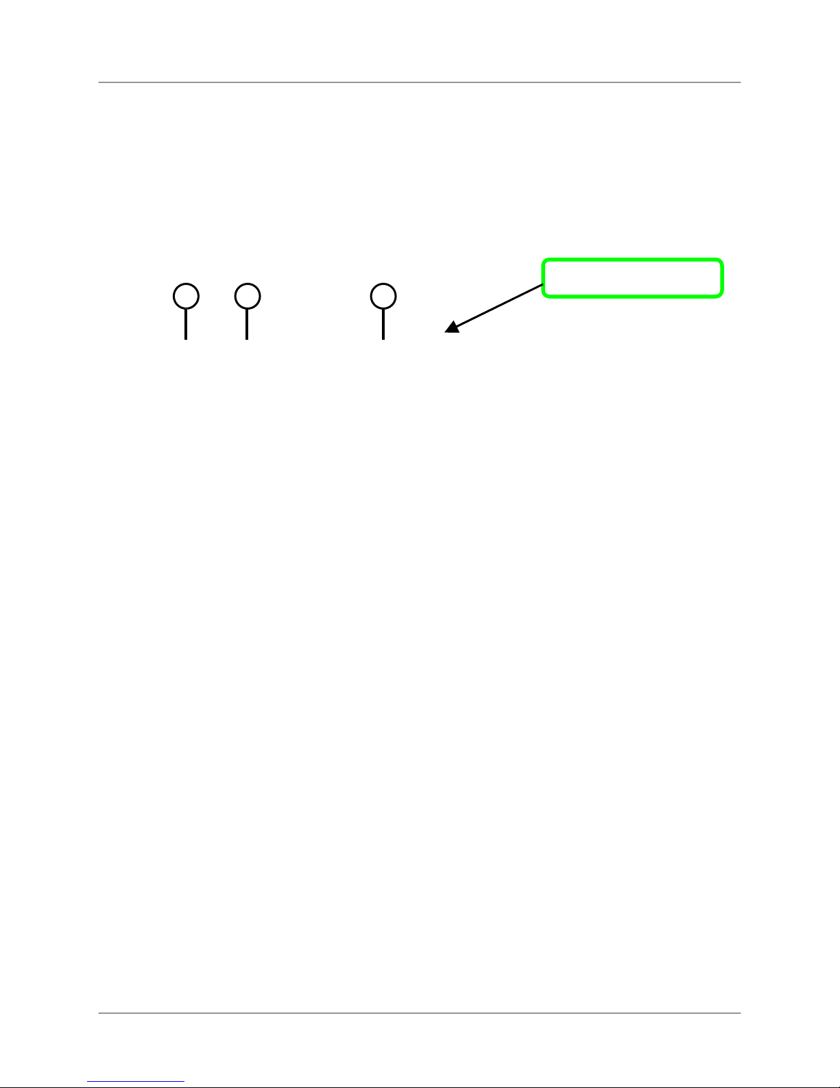
Make the following connections prior to starting the system for the first time.
Connect the cameras to the monitor
Front Panel
Please see the Camera Installation section of this
manual for details.
ATTENTION: Test the cameras prior to permanently
mounting them by temporarily connecting the
cameras and cables to your system.
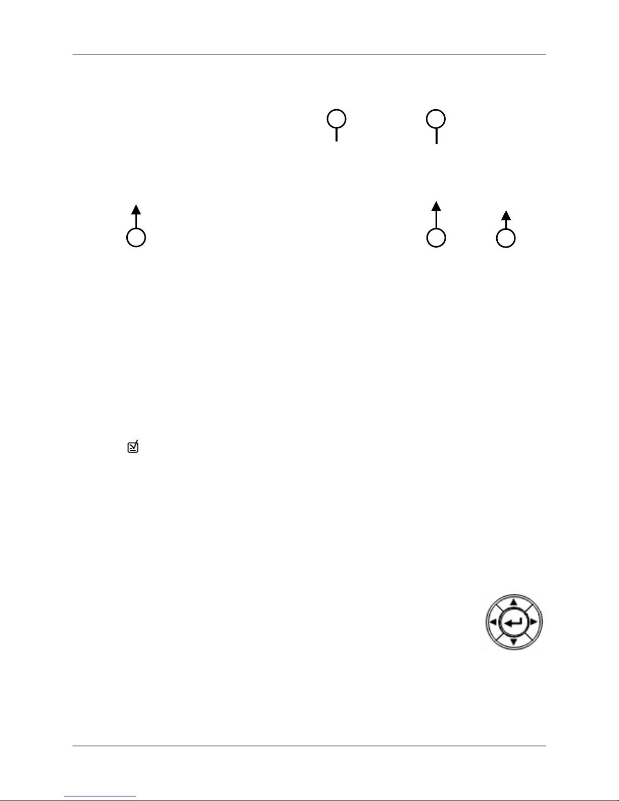
2. Connect the Ethernet cable
Connect one end of the Ethernet cable (for remote
monitoring) to the LAN port on a router (not included),
and the other end to the Ethernet port on the back of
the system.
3. Connect the mouse
Connect a PS/2 mouse to the port on the back of the
system.
4. Connect the power cable
Connect one end of the power adaptor to the monitor
and the other end to an electrical outlet.
Note: The system automatically powers on once connected to a
power source. By default, all connected cameras are set to record
in Continuous Mode when the system is first powered on.
5. Login to the system
10
After the initial startup sequence, you will need to
login to the system when accessing the System
Main Menu (press the MENU button). To login,
leave the default user as ADMIN. Leave the
password field blank and click OK. Fore more
details, see “Starting the System,” page 24.
Page 15
Front Panel
L19WD Series
2 3 1
4
8-channel model
1. IR Sensor: Receives the infrared signal from the remote control.
2. Function Buttons: The left set of function buttons consist of the following:
• Menu: Press to enter the System Main Menu; press and hold to power off the
monitor.
• Mode: Switch between screen displays – full-screen, quad, and split-screen view.
• Search: Search for recorded video on the HDD.
• Zoom: Zoom in/out of an image using digital zoom.
• PTZ: Open the control menu for Pan, Tilt, Zoom – a PTZ camera (not included)
must be connected to the system to make use of the PTZ menu.
• SEQ: Activate sequence function in any display mode.
• FRZ: Freeze live image.
• PIP: Picture-in-Picture mode.
3. Numeric Keypad and Playback Buttons*:
• 1~8: Press to view each channel of the system in full-screen mode.
• 1+: In PTZ Mode: zoom in.
• 2-: In PTZ Mode: zoom out.
• 3+: In PTZ Mode, channel up.
• 4-: In PTZ Mode, channel down.
*Only on L19WD800 Series. 16-button numeric keypad found on
L19WD1600 Series
11
Page 16
Front Panel (cont’d).
Front Panel (cont’d).
3
4
5
6
3. Numeric Keypad and Playback Buttons (cont’d):
• In Playback Mode, jump to start of recording
• Slow motion speeds in Forward Playback: 1/4, 1/8, 1/16, and 1/32;
Increase playback speed in Reverse Playback: 2X, 4X, 16X, and 32X.
• Reverse playback; in Login Menu, also used as Backspace to delete digits.
• Play
• Pause
• Stop
• Increase playback speed in Forward Playback: 2X, 4X, 16X, and 32X;
Slow motion speeds in Reverse Playback: 1/4, 1/8, 1/16, and 1/32.
• In Playback Mode, jump to end of recording
•
In Playback Mode, set a bookmark for future reference in Search Mode.
4. LED Indicator: Four lights show the status of the system: Power, Record, Backup, and
Network.
5. USB Port: USB 2.0 port for data backup and uploading firmware updates.
6. Function Buttons: The right set of function buttons consist of the following:
• Panic: In an emergency, press Panic for Continuous recording with High Quality
Video. Panic Recording overrides any active recording mode or function of the
system.
• Exit: Press to exit menus / functions or to stop playback.
• Audio: Select audio channel; mute internal speaker.
7. Navigation Arrows: Use the arrows and Enter button to select Menu
options.
• Enter:
Forward & Reverse Playback, Pause; hold to display system
information.
• Left: Increase playback speeds in Reverse playback; Slow Motion
speeds in Forward playback
• Right: Increase playback speeds in Forward playback; Slow Motion speeds in
Reverse playback
• Up: In Live mode or during playback, increase the volume of the internal speaker.
• Down: In Live mode or during playback, decrease the volume of the internal speaker.
7
12
Page 17
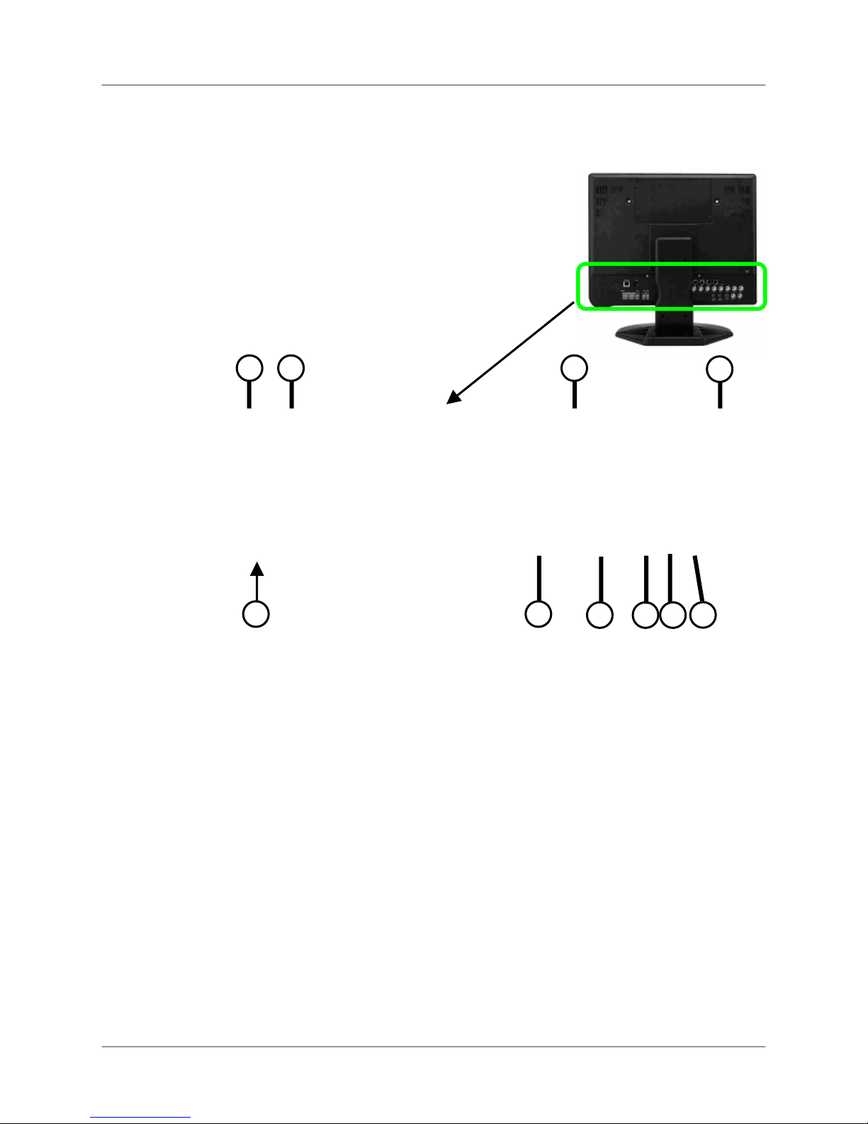
Rear Panel
2
1
L19WD Series
3
4
5
6
8 7
9
Ethernet Port: Connects the System to a router or switch for networking purposes.
PS/2 Mouse: Dedicated connection for a PS/2 mouse.
6-pin DIN Camera Inputs*: Channels 1~4 for 6-pin DIN cameras. Cameras with 6-pin DIN
connectors draw power from the system; additional power adaptors are not required.
DC Input: Connects the system to the power adaptor.
Relay/PTZ/RS-232 Block: These terminals send a signal to a secondary device or control
Pan, Tilt, Zoom cameras.
BNC Camera Inputs†: BNC video ports for channels 1-8; cameras with BNC connection
require an additional power adaptor.
RCA Audio Inputs (2)**: Audio inputs for channels 1~4 and channels 5~8.
Audio Out: Audio output port to connect to speakers, or a secondary DVR, or TV.
Monitor Out: Connect a secondary monitor; directly reflects the onscreen images.
Spot Out: Spot video output to a secondary monitor to view the active video channels in
sequence. Use in situations where the system will be in a backroom, but you want to
display images to the public, whether for theft deterrence or advertising purposes.
*6-pin DIN ports only on L19WD800 Series
**Four audio inputs on L19WD1600 Series
†16 BNC ports and 16 alarm ports available on L19WD1600 Series
10
13
Page 18

Camera Installation
Camera Installation
Before you install a camera*, carefully plan where and how it will be positioned, and where you
will route the cable that connects the camera to the DVR.
Installation Warnings
• Select a location for the camera that provides a clear view of the area you want to
monitor, which is free from dust, and is not in line-of-sight to a strong light source or
direct sunlight.
• Plan the cables’ route so that it is not close to power or telephone lines, transformers,
microwave ovens or other electrical equipment that could interfere with the DVR.
• Select a location for the camera that has an ambient temperature between 14°F~113°F
(-10°C~45°C)
• If you plan to install the camera in a location that has conditions not recommended in
this manual, consult with a professional installer and consider use of a separate camera
cover or housing
• Before starting permanent installation, have another person hold the camera for you
while you verify its performance by observing the image on a monitor.
Camera Stand Installation
1. Attach the pedestal to the ceiling, wall or other surface
by the base using the provided screws.
2. The mounting bracket must be attached to a structural
device such as a wall stud or ceiling rafter using the
supplied screws.
3. Attach the camera to the pedestal. Adjust the angle of
the camera, and tighten the thumbscrew to set the position
Note: The camera can be attached to the stand using
the screw point on the top or the bottom (to maintain
proper camera alignment). This prevents the image
from becoming inverted.
* Camera may not be exactly as shown
14
Page 19
Connecting DIN Cameras
Connect the female end of the extension cable (not included) to the camera.
L19WD Series
Note: Ensure that the arrows on the DIN
Camera Cable and the DIN Extension Ca
ble point together when connecting the ca
ble. If the pins in the DIN Cable are bent, t
he camera will not function.
Connect the male end of the extension cable to an open DIN camera input on the rear panel of
the system.
Note: The arrow on the DIN camera should be facing up when connecting the DIN Extension Cable to
the system.
15
Page 20
Connecting BNC Cameras
Connecting BNC Cameras
1. Connect the extension cable to the Camera and system:
A. Connect the Barrel Power connector to
a power adaptor.
B. Connect the BNC connector to an
available BNC Port on the DVR.
C. Connect the Male Power connector to
the Camera.
D. Connect the BNC connector to the
Camera.
2. Connect the Power Adaptor to a wall outlet.
ATTENTION: The ends of the extension cable are NOT the same - one end has a Male power port,
and the other has a Female power port. Before permanently running the Camera Extension Cable,
make sure that the cable has been oriented between the Camera and the unit correctly.
Male Power Port - The male power
port end of the Extension cable
connects to the Camera.
Connect to DVR and
Power Adaptor
Female Power Port - The female
power port end of the Extension cable
connects to the Power Adaptor.
Camera Connection Diagram
16
Page 21
L19WD Series
Mouse Control
This system has been designed to use a PS/2 mouse or remote control as its primary methods
of navigation and configuration. Connect the mouse to the PS/2 port located on the rear panel
before powering on the system. Once the system has started up it will recognize the mouse.
Using the mouse
The mouse functions in the same manner as a PC mouse. Use the left and right buttons to open
menus and change options.
Left Button
Click:
• Select options and
change values in
menus, Recording
mode, and Search
mode
• Operate controls in
PTZ mode
Double-click:
• Double-click on a
channel in Quad or
split-screen view to
view the channel in
full-screen.
Right Button
Right-click:
• Switch between active
camera channels in fullscreen mode, or switch
between groups of channels
in Quad or split-screen views
• Motion Setup: Set motion
cells
• Digital Information Display
(DID): While running, rightclick in top-right corner of
screen to return to Live
Mode
Scroll-Wheel
• In PTZ Mode, Scroll Up
to Zoom In, Scroll Down
to Zoom Out.
• Changes values in
certain menus.
17
Page 22
Mouse Control
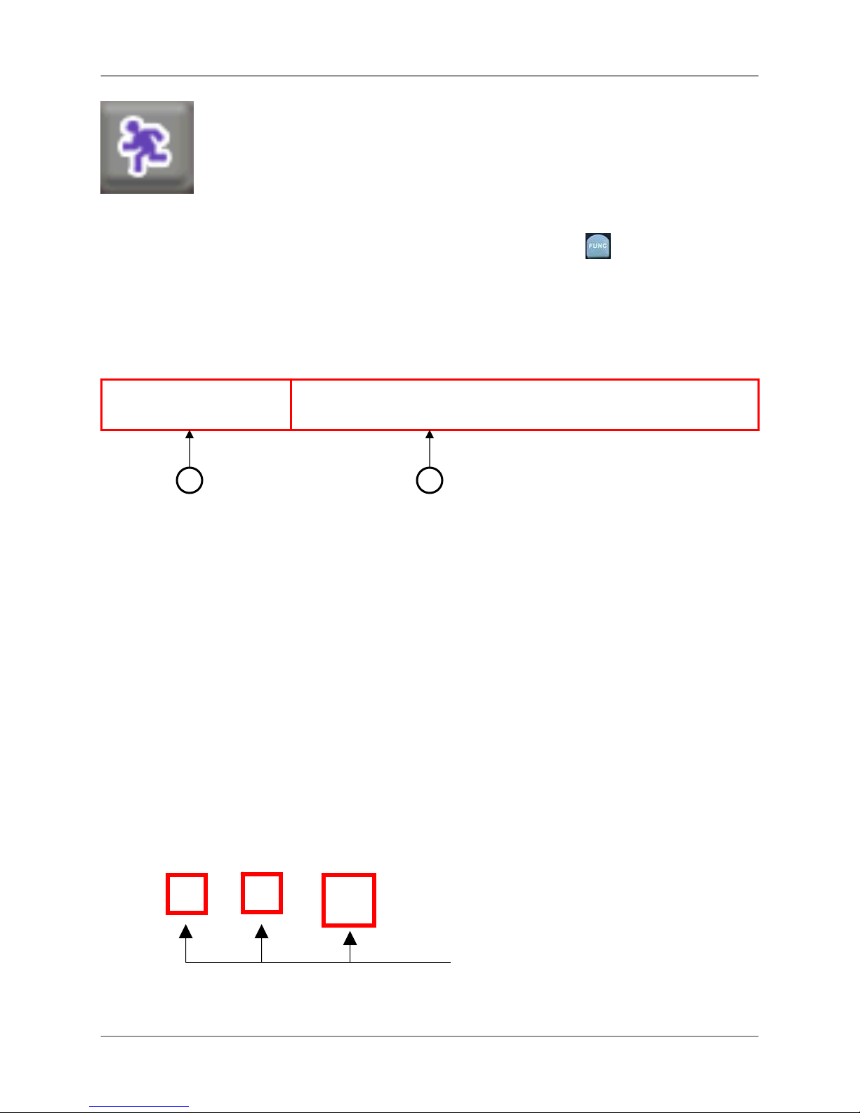
Function Bar
When using the mouse, the Function Bar is the primary on-screen tool for
accessing and changing system settings and configurations.
To open the Function Bar:
Mouse:
• Move the cursor over the bottom of the
screen.
RemoteControl:
• Press the button.
The Function Bar contains two main components:
1. Channel Display
2. Function Icons
1
2
Channel Display
Click the icon to view the status of each camera in Alarm, Cam-Loss, or Motion.
Alarm: Panic recording. Panic Recording overrides all other active recording modes
of the system.
Cam-Loss: The camera has become disconnected or the signal has been lost.
Motion: Recording triggered by motion detection.
Example of camera loss:
18
The Function Bar shows that cameras 3
and 7 have been disconnected.
Page 23
Function Icons
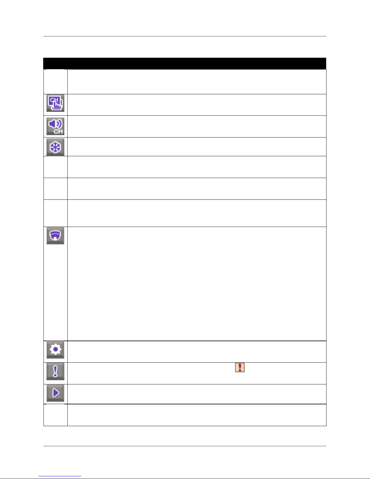
Icon Description
DISPLAY: Switches between Full-Screen, Quad, and split-screen views.
CHANNEL: Click to view any channel in Full-Screen mode.
L19WD Series
AUDIO: Select an audio channel from 1~4; click OFF to turn off audio.
FREEZE: Freezes the image. Press ESC to cancel Freeze Mode.
SEQUENCE: Activates Sequence Mode for the connected cameras only. You can set the
display view (Full-Screen, Quad, 9-split) prior to activating Sequence Mode.
ZOOM: In Live mode, the image zooms in 2X in Full-Screen view. Click and drag the small
blue box in the bottom-right corner of the screen to view other areas of the image or use the
Navigation buttons on the Remote Control.
PIP: Activates the Picture-In-Picture (PIP) function.
One channel appears in Full-Screen, while another appears in a sm all inset window. The
small screen displays in sequence according to a preset interval.
PTZ: Opens the Pan, Tilt, Zoom (PTZ) Control Panel.
Note: PTZ cameras
are not included with
this system. See
Appendix 10 for more
o NEAR
o FAR
o OPEN
o CLOSE
o SET
SETTINGS: Opens the System Control Panel (login: ADMIN; leave the password field blank).
See Using the System: Configuration for more details on changing your password.
PANIC: In case of emergency, click to start Panic Recording.
system records in Continuous mode at highest video quality. Press again to cancel.
PLAYBACK: Click to playback recorded video. Pop-up control panel supports, play, pause,
forward/reverse, and next/previous.
SEARCH: Opens the Search menu; scan for recorded video by Date/Time, Event, or
Bookmark.
Focus near
Focus far
Open iris
Close iris
Set preset
o GO TO
o AUTO
o PRESET
Go to preset
Auto scan
Enter present number
Appears on all channels;
19
Page 24
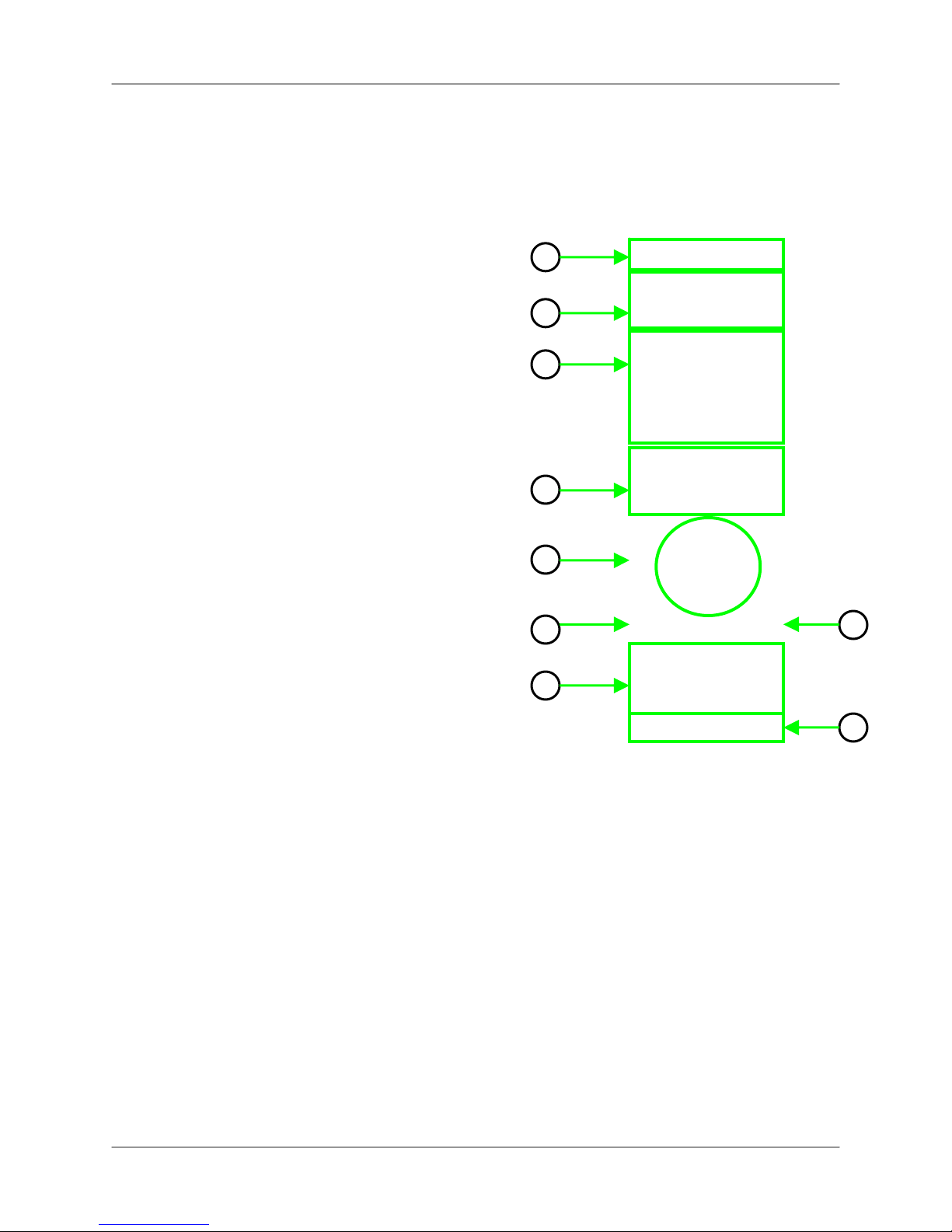
Remote Control
Remote Control
Listed below is a quick reference for the Remote Control.
1. REC: Press REC to start Panic recording on the DVR.
MENU: Press to open the System Main Menu.
2. DVR 1-6: Select DVR ID for controlling multiple systems.
3. Numeric Keypad, – +: Press number buttons to cycle
through individual channels in full-screen mode*; Press
to cycle through display modes: full-screen, quad,
,+
eight.
4. FUNC: Opens and closes the Function control bar.
SEARCH: Opens the search menu.
ESC: Exits menus, functions; stops playback.
AUDIO: Switch audio inputs (Ch. 1~4) or mute the
internal speaker.
MODE: Change screen displays: full-screen, Quad and
Split-Screen views.
5. ◄▲▼►, OK (Navigation Buttons): Cycle through
menu options and change values. Operate PTZ
functions.
6. PTZ: Opens the PTZ menu.
7. Playback controls:
o Jump to start of recording
Slow motion speeds in Forward Playback: 1/4, 1/8,
o
1/16, and 1/32; Increase playback speed in
Reverse Playback: 2X, 4X, 16X, and 32X.
o
Reverse Playback
o Forward Playback
o Pause
Stop
o
o Increase playback speed in Forward Playback: 2X,
4X, 16X, and 32X; Slow motion speeds in Reverse
Playback: 1/4, 1/8, 1/16, and 1/32.
o
Jump to end of recording.
8. BACKUP: Opens the USB Backup menu.
9. SEQ, FRZ, PIP, ZOOM:
o SEQ Automatically cycle channels in sequence.
Select full-screen, Quad, or Eight-view prior to
pressing SEQ.
o FRZ In full-screen mode, freeze image; press Esc to
cancel. In Quad and Eight-view, activate freeze
features, then press corresponding numeric button
to freeze the image; press Esc to cancel.
o PIP Turn on picture-in-picture view.
o ZOOM Activate full-screen zoom mode. Use
navigation arrows to scan image; press ESC to
cancel.
1
–
2
3
4
5
6
7
*L19WD1600 series only: 0+0 = 10,
0+1 = 11, etc.
8
9
20
Page 25
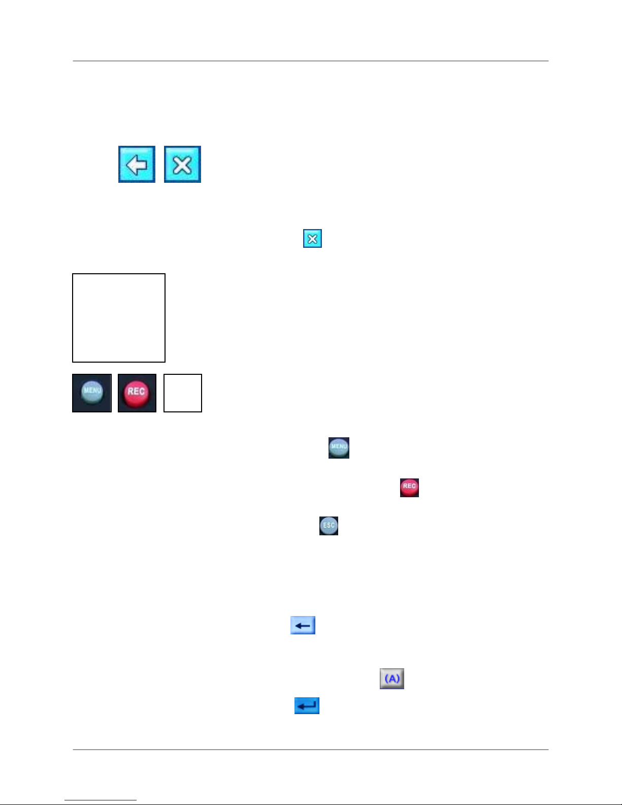
Menu Navigation Control & Tips
Using the Navigation Icons
Use the Navigation Icons when navigating the system menus.
• HOME: Cli ck while in any menu to return to the System
Main Menu.
L19WD Series
• BACK: Click
• EXIT: Click
to return to the previous menu.
to exit menus.
Using the Navigation Buttons
When using the remote control, the Navigation Buttons are
the primary way to move through the system menus.
• ◄► Press the Left and Right arrow buttons to choo se different
options in menus.
• ▲▼ Press the Up and Down arro w buttons to change values
within options. These buttons can also choose different menu
options in certain menus.
• OK Press the
selections.
• MENU Press the
you must first login with your user name and password.
• REC In an emergency, press the
Recording; press again to cancel.
button to change option values and confirm
button to open the System Main Menu;
button to start Panic
• ESC Press the
button to close windows and menus.
Using the Virtual Keyboard
You need to use the Virtual Keyboard to change user
passwords and to edit camera names.
1. Click
title.
2. Enter a new password or camera title using the alphanumeric keypad. Press
3. Press
to delete the default password or camera
to change case.
to save changes and close the Virtual
21
Page 26
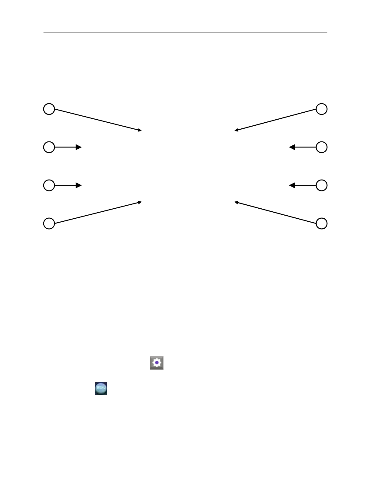
System Main Menu
System Main Menu
2 3
1
5
6
1. CONFIGURATION
2. DISPLAY
3. HDD MANAGEMENT
4. CAMERA
4
8
7
5. RECORD
6. BACKUP/UPGRADE
7. NETWORK
8. LANGUAGE
To open the System Main Menu:
Mouse:
• From the Function Bar, click .
Remote Control:
• Press the
Note: You must login to the system before you can access the System Main Menu.
22
button.
Page 27

System Control Panel Icons
Icon Description
CONFIGURATION: Set Date/Time, Passwords, User Authority, Audio, System
Information, and restore factory defaults.
DISPLAY: Change display settings, adjust resolution, and enable DID Mode (Di gital
Information Display).
HDD MANAGEMENT: Format hard disk and enable/disable disk overwrite.
CAMERA: Change Camera Title, adjust color, camera settings, alarm, motion, and
PTZ settings, and set Event pop-up.
RECORD: Configure Record Setup, Schedule, and Holiday settings.
L19WD Series
BACKUP/UPGRADE: Backup data to USB storage device; upgrade firmware.
NETWORK: Adjust IP settings and connections, and enable/disable DDNS.
LANGUAGE: Change the system language to English, French, or Spanish.
23
Page 28
Starting the System
Starting the System
Once you have made all connections to the system and powered it on, you must login to the
system and set the date and time.
Note: By default, the primary user of the system is the ADMIN (administrator). The ADMIN has full
access and authority to the system.
ATTENTION: When first logging in to the system, keep ADMIN as
your user name and leave the password field blank. See Using the
System: Configuration for more details on changing your password.
To log into the system:
Mouse:
1. Move the cursor toward the bottom of the screen to open the Function Bar.
From the Function Bar, click .
Select your user name and password and click OK.
Remote Control:
1. Press the
Use the Navigation Buttons and Numeric Keypad to select your username and password.
Select OK.
Note: You must login when accessing the following critical menus:
o Search
o PTZ
o HDD Clear
o Backup
button.
24
Page 29
Setting the Date and Time
ATTENTION: You must set the date and time prior to setting a
recording schedule on the system. See Using the System: Record for
more details on setting a recording schedule.
To set the date and time:
L19WD Series
Mouse:
1. From the System Main Menu, click
.
2. From the Configuration menu click DATE/TIME.
3. Click +/- to change the DISPLAY FORMAT, TIME ZONE and Date and Time for the
system. Check the DST box to enable Daylight Savings Time.
4. Click OK to save your settings or click DEFAULT to restore factory defaults.
5. Click
to exit.
Remote control:
1. Press the
2. Using the Navigation Buttons, select
between menu options. Use
button and login to the system.
then select DATE/TIME. Use ◄►to cycle
▲▼to change individual settings.
3. Select the DISPLAY FORMAT, TIME ZONE and Date and Time for the system.
4. Check the DST box to set Daylight Savings Time.
5. Select OK to save your settings or select DEFAULT to restore factory defaults.
6. Press the
button to exit.
25
Page 30
Starting the System
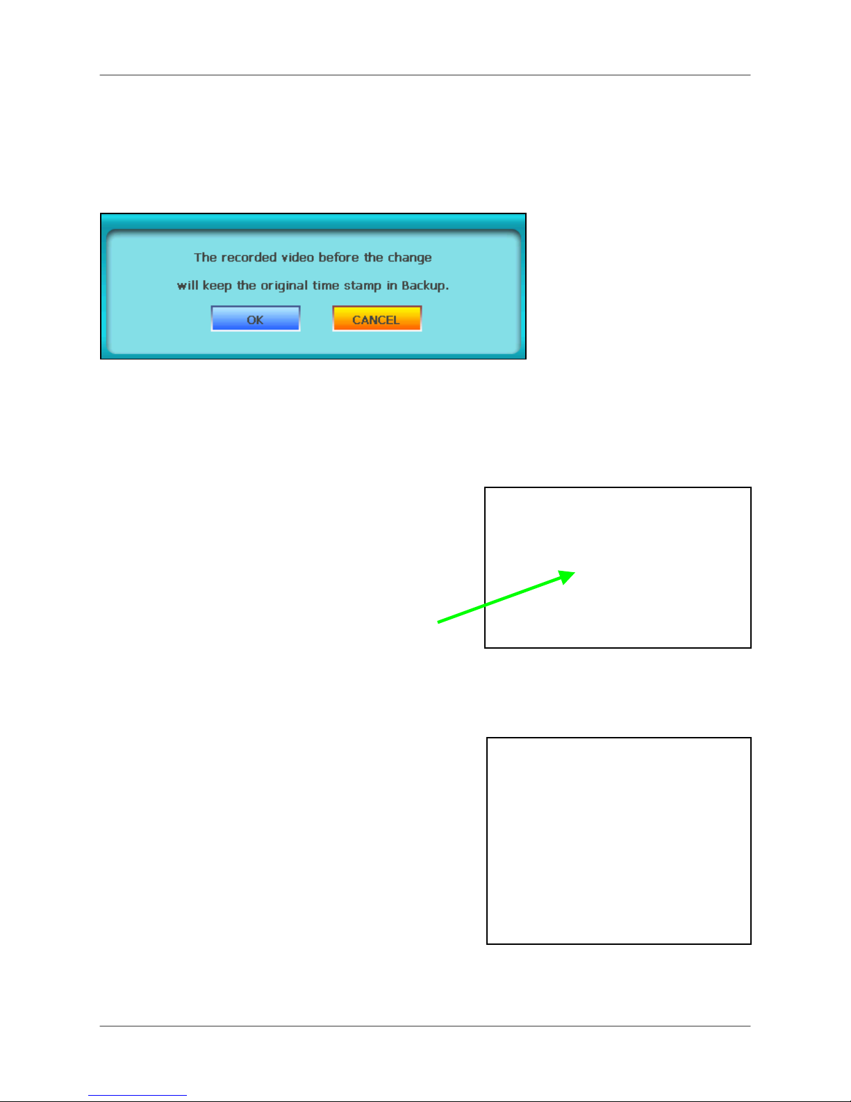
Time Stamp
When you change the date and time after recording video data. A pop-up window appears
informing you that the recorded video before the time change will keep the original time stamp.
The same applies for changes to Daylight Savings Time (DST).
Turning the monitor off (Screen Saver)
• From the front panel, pre ss and hold the MENU button
for three seconds.
• The system continues to record while the monitor is shut
off. LED lights remain lit on the front panel. This is useful
to disguise the fact that the system is a security monitor.
• Press the MENU button again to turn the monitor back on.
Note: Only pressing the MENU button will turn the monitor
back on.
26
Page 31

Turning the monitor off (cont’d.)
The monitor can also be set into Screen Saver mode:
L19WD Series
1. From the System Control Panel click
and then click VGA.
2. Under Screen Saver, select ON.
3. Enter the SCREEN OFF time and SCREEN
ON time. The system uses the 24-hour
clock.
4. Click OK to save your settings or click
DEFAULT to restore factory defaults.
Note: For details setting the Screen Saver
(automatically turning the monitor on/off), see page 39.
27
Page 32

Display Modes
Display Modes
The system features the following modes:
• Live Mode
• Full-Screen, Quad, &
Split-Screen views
Live Mode
1
2
• Playback Mode
• Search Mode
4
5
6
3
7
1. Live: Displays the Live view of each camera. Available in Full-Screen, Quad, and Split-
Screen views.
2. Camera Title: Displays the name of each camera by channel. You can change the name of
each camera channel in the Camera menu of the System Control Panel.
3. Date/Time: Shows the date/time, network status, active audio channel and used hard disk
space.
4. Recording Mode: The system uses the following icons to indicate its recording status:
• Alarm
•
28
Continuous
• Motion
• Panic
Page 33

L19WD Series
5. Function Bar: Fast, mouse-driven access to the many functions of the System.
6. Hard drive space: Shows the percentage of used hard drive space.
7. Audio: Shows the active audio channels or the mute internal speaker.
Full-Screen, Quad, & Split Views
The L19WD Series has several display views available: Full-Screen, Quad-View, and SplitScreen Views. You can easily change the display view through the system’s three input
methods: mouse, remote control, and front panel.
Full-Screen View Quad View 8-Split View 16-Split View*
To change display views:
Mouse:
• From the function bar, click :
Remote Control:
• Press the MODE button to cycle through the display modes.
Front Panel:
• Press the MODE button to cycle through the display modes.
*16-split screen view only available on L19WD1600 Series.
Full-Screen
Quad-View
Split-Screen View*
29
Page 34

Display Modes
:
Playback
View recorded video on the system through Playback mode.
To open Playback mode:
Playback Bar Icons
Mouse:
1. While in Live Mode, move the
2. Click
cursor over the bottom of the
screen.
and login with your
username and password.
Remote Control
1. Press the
► button.
2. Enter your username and
password and select OK.
Icon Description
BOOKMARK: Click to bookmark a point in playback for future reference.
DISPLAY: Switch between Full-Screen, Quad, and Split views.
DISPLAY CHANNEL: Select to view any channel in Full-Screen mode.
AUDIO CHANNEL: Select audio channels 1 or 2*; click OFF to turn off audio.
SEARCH: Open the Search Menu to view playback recorded video.
BACK: Move to the start of all recorded video.
REVERSE PLAYBACK: View playback in reverse.
PAUSE: Pause playback.
PLAY: Start playback.
END: Move playback to the end and stop.
SLOW MOTION PLAY: Slow motion speeds in Forward Playback: 1/4, 1/8, 1/16, and 1/32;
Increase playback speed in Reverse Playback: 2X, 4X, 16X, and 32X.
FAST FORWARD: Increase playback speed in Forward Playback: 2X, 4X, 16X, and 32X;
Slow motion speeds in Forward Playback: 1/4, 1/8, 1/16, and 1/32.
EXIT: Quit Playback Mode.
*Audio configuration varies by model.
30
Page 35

Search Mode
Search the system for recorded video by date / time, event, and
bookmarks.
DATE/TIME
Search for recorded video data according
to date and time.
Note: START TIME and END TIME in the
DATE/TIME menu shows the start and end
of recording. They cannot be edited.
To open the Search Menu:
Mouse:
1. From the Function Bar, click
2. Enter your username and password
and click OK.
Remote Control:
L19WD Series
1. Press the
.
2. Use the navigation buttons to
button.
enter your username and
password and select OK.
EVENT
Search for recorded video data according
to Events. Events include Motion, Alarms,
and Video Loss from any of the cameras.
• TIME SEARCH: Click +/- to enter the Date
and Time and click Search.
• PERCENT SEARCH: Click +/- or click
anywhere in the progress bar to search a
certain portion of the recording time.
• Click ▲▼ to scroll through the event list.
Click to view the previous hundred events.
Click to view the previous ten events.
Click to view the next hundred events.
Click to view the next ten events.
31
Page 36

Using the System
BOOKMARK
Search for recorded video data according
to Bookmarks.
To search video data by bookmark:
1. Open the Search menu and click
BOOKMARK.
2. Click one of the bookmarks from the list
and click PLAY. If you have many
bookmarks, click
▲▼ to scroll
through the bookmark list.
Setting Bookmarks
You can set bookmarks in recorded video
data to mark unique moments of activity or
interest for future reference.
To set bookmarks:
1. Search for recorded video by either
DATE/TIME or EVENT. The Playback
Control Bar appears during playback.
2. From the Playback Control Bar, click
. A dialogue window informs you
to wait and then playback resumes.
Note: The system can save a maximum of
1000 bookmarks.
To delete bookmarks:
1. Open the Search menu and click
BOOKMARK.
2. Select a bookmark and then click
DELETE.
Note: You can only delete one bookmark
at a time.
32
Page 37

Using the System
You can now begin to explore the main menu of your system.
Configuration
Open the Configuration menu from the System Control Panel to adjust
various system settings.
L19WD Series
BUZZER
Select the boxes to turn system beep,
alarms, and buzzer sounds on/off.
• KEY BEEP: Beeps when you click the
mouse or press buttons on the remote
control.
• VIDEO LOSS: Alarm sound when video
signal is lost from a camera.
• ALARM IN: Alarm sound for connected
external security alarm.
• MOTION DETECT: Alarm sound whenever
motion is detected.
Click OK to save your settings, or click
DEFAULT to restore factory defaults.
PASSWORD SETUP
Set passwords for the various users of the
system. Only the ADMIN can change
passwords for users on the system.
To change your password:
1. Click
◄► to select the USER. The
Virtual Keyboard opens.
2. Select USER PASSWORD, and use
the Virtual Keyboard to enter the
current password for that user.
3. Under NEW PASSWORD, enter a
new password for the selected user.
4. Re-enter the new password to
confirm and click OK.
See Using the Virtual Keyboard for more
details on using the Virtual Keyboard.
Note: The password has a maximum length
of ten digits.
33
Page 38

Using the System
The system has a total of ten users:
User Default Password
ADMIN [leave blank]
MANAGER1 1
MANAGER2 2
MANAGER3 3
USER1 1
USER2 2
USER3 3
USER4 4
USER5 5
USER6 6
You can log in to the system using any of
these default users, though only ADMIN
has full access to all functions of the
system.
Note: Gray, non-selectable menu options
mean the logged-in user does not have
authority to access those options.
Note: The number of connected users can
affect network performance. No more than
4~5 users should be logged-in to the system
at the same time. Please keep in mind your
bandwidth restrictions and LAN settings if
allowing multiple users to access the system
at once.
Resetting Passwords
If you forget a user password or the
administrator password, please contact
Technical Support.
USER AUTHORITY
If many people will be operating the
system, the system administrator (ADMIN)
can set restrictions on which system
options users can access.
Note: By default, ADMIN has access to all
system options.
Select the boxes to limit access to system
options for different users:
• CONFIGURATION: Change various system
settings including date & time and passwords.
• DISPLAY: Change graphic displays on the main
System Screen and Playback Screen.
• HDD MANAGEMENT: Format the hard disk and
set disk Overwrite On/Off.
• CAMERA: Rename camera channels, adjust
color and brightness, and adjust settings for
motion sensitivity.
• RECORD: Adjust record settings, along with
recording schedule.
• BACKUP/UPGRADE: Backup data to an
external device via USB or update the system’s
firmware.
• NETWORK: Change network IP settings, Web
Server, and enable DDNS for remote viewing of
the system.
• LANGUAGE: Change the system language to
English, Spanish, or French.
• SEARCH: Search the system for recorded data.
Search by date & time, events, and bookmarks.
•
PTZ: Change settings for PTZ cameras (not
included).
Click OK to save your settings, or click
DEFAULT to restore factory defaults.
For more details, see Appendix L.
34
Page 39

RS-232C
L19WD Series
REMOTE CONTROL
Adjust settings for an external
communication device.
• BAUDRATE: Transmission speed between
the system and the device.
• LENGTH: The length of the transmissio n
signal.
• STOP BIT: Bit that indicates that a piece of
information has just been transmitted.
• PARITY: Can help detect errors in
transmission.
• FLOW CONT ROL: Assign control of signal
transmission to hardware or software.
Click OK to save your settings, or click
DEFAULT to restore factory defaults.
Set the remote control up to six units of the
L19WD series.
To assign remote control functionality:
1. From the Remote Control drop-down
menu, select ALL to control up to six
systems simultaneously.
OR
1. Select 1-6 to assign a specific
L19WD series unit to the remote
control.
2. Press the corresponding button on
the remote control (DVR1 – DVR6) to
control only that specific system.
Click OK to save your settings, or click
DEFAULT to restore factory defaults.
Note: If you select 01 in the Remote Control
settings, you must press DVR1 on the
remote control to operate the system.
35
Page 40

Using the System
AUDIO*
Set volume levels for the two audio inputs of
the system.
To change audio settings:
Mouse:
1. Drag the bar left/right to adjust the
volume.
2. Select the radio button to assign
audio recording to one of the four 6pin DIN cameras. DIN cameras can
only be connected in channels 1~4.†
Remote Control:
1. Press
channel, and then press
◄►to select an audio
▲▼to
adjust the volume.
2. Press
◄►to select the buttons, then
press OK to check.
Click OK to save your settings, or click
DEFAULT to restore factory defaults.
ATTENTION: You can only record two
channels of audio on the system**: one
audio-capable BNC camera or one DIN
camera records audio for channels 1~4; one
audio-capable BNC camera records audio for
channels 5~8. You cannot have a DIN
camera and an audio-capable BNC camera
recording audio at the same time on
channels 1~4.
*Audio capable cameras may not be included
with your system.
**Four audio channels on the L19WD1600.
† Audio control for DIN cameras only
available on L19WD800.
SYSTEM INFORMATION
View important system information:
• IP Address: The IP address of the system
when on a network.
• MAC Address: MAC address of the
system. Necessary for networking or setting
up remote viewing.
• Disk Capacity: Displays the total size of the
system hard disk and amount presently in
use.
• F/W Version: Firmware version.
• Video Signal Type: Video format of the
system: either NTSC in North America or
PAL in Europe.
• DDNS Domain Name: Domain name used
with the Lorex Client Software to let you
view your system remotely over the Internet
from another PC.
• Net Client Port: The port that allows your
system to communicate to other PCs or
devices over a network. By default, the Net
Client port is 5000.
• Web Server Port: The Web Server port (by
default, 80) to let external PCs or devices
communicate with your system over the
Internet.
36
Page 41

FACTORY DEFAULT
Reset factory defaults on System, Channel
Data, PTZ, Network, or Record data.
Note: Resetting factory defaults will not erase
recorded data from your hard disk.
To reset factory defaults:
• Select the box, SELECT ALL, to reset all
settings
OR
• Select the individual boxes for SYSTEM,
CHANNEL, PTZ, NETWORK, and
RECORD settings.
Click OK to save your settings, or click
DEFAULT to restore factory defaults.
Note: Network is excluded from SELECT
ALL. To reset your network settings to factory
defaults, select the Network box individually.
L19WD Series
37
Page 42

Using the System
play (
Display
Open the Display menu from the System Control Panel to set graphical
displays during Live view and Playback, and edit settings for the Digital
Information Dis
DID).
DISPLAY SETUP
Select the boxes to turn graphical displays in
Live mode and Playback on/off.
• DATE/TIME: Shows the date and time in
the lower left corner.
• CHANNEL STATUS: The active status for
each of the cameras: Continuous, Motion,
Alarm, or Panic.
• TOTAL STATUS: Show the percentage of
the hard drive currently in use. Also shows
the active Audio Channel.
• CAMERA TITLE: Display the name of the
camera channels.
INTERVAL
Set the time intervals for Sequence Mode
(SEQ), Picture-In-Picture (PIP), and Spot
Monitor. You can also set the timeout for
the on-screen menu. A short timeout
means any on-screen menus will
disappear quickly without user input; a
longer timeout means menus will remain
on-screen longer.
To change time intervals:
Mouse:
1. Click ◄► to adjust the time interval (in
seconds) for SEQ, PIP, and Spot
Monitor.
Click OK to save your settings, or click
DEFAULT to restore factory defaults.
38
2. Under TIMEOUT, click the drop-down
menu to adjust the timeout of the onscreen menu.
Remote Control:
1. Press ◄►to select between SEQ, PIP,
and Spot Monitor, then press ▲▼to
change the time increment.
2. Press ◄►to select the drop-down
menu, and then press OK to select a
time interval for the menu timeout.
Click OK to save your settings, or click
DEFAULT to restore factory defaults.
Page 43

L19WD Series
VGA
Set the system’s screen resolution and adjust
the settings for the Screen Saver (automatically
turn monitor on/off).
• RESOLUTION: Select 16:9 widescreen or
4:3 full screen.
• SCREEN SAVER: Select to turn the monitor
on or off. If On, you must select an Off Time
and On Time for the Screen Saver.
Note: The Screen Saver feature can be
useful if you need to disguise the fact that
your system is a security monitor.
DIGITAL INFORMATION DISPLAY (DID)
Use Lorex Message Master (included on the
Software CD) to send text and digital images
(JPEG) to the system. Use the text and still
images for announcements, advertising, or
other retail purposes.
• STILL IMAGE DISPLAY: Display a slide
show of still images (JPEG)
• STILL IMAGE/TEXT MESSAGE DISPLAY:
Display both a still image slide show and
text
• SCREEN OFF: Click
24 HRs) that the monitor will automatically
turn off. For example, if you want the
monitor to automatically turn off at 11 PM,
enter 23:00.
• SCREEN ON: Click
24 HRs) that the monitor will automatically
turn on. For example, if you want the
monitor to automatically turn on at 6 AM,
enter 6:00.
Note: The system continues to record while
the monitor is turned off.
to set the time (in
to set the time (in
Click OK to save your settings, or click
DEFAULT to restore factory settings.
Note: When the monitor is turned off, press
and hold the MENU button on the front panel
to turn the monitor on. Only the MENU button
can turn the monitor back on.
• TEXT MESSAGE DISPLAY: Display still or
moving text at the bottom of the screen.
• DID PORT: By default, 1280 is the fixed
port for the system to communicate with
Lorex Message Master. You set the port to
whichever port you want using the Virtual
Keyboard.
• SEQUENCE DWELL TIME: Set the length
of time (in seconds) that the digital images
remain on screen.
• FILE COPY BY USB: Copy JPG files from a
USB to the system to use in the DID slide
show.
39
Page 44

Using the System
DIGITAL INFORMATION DISPLAY (cont’d)
To start the image/text message display:
1. Select the radio buttons for STILL
IMAGE, TEXT MESSAGE DISPLAY
or STILL IMAGE/TEXTMESSAGE
DISPLAY.
>
2. Click OK. The slide show/text display
starts.
To copy files from a USB flash drive:
1. Connect an empty USB flash drive to
your computer and create a new
folder on the drive. Give it any name,
such as PICTURES.
2. Copy JPG files (up to 1.2MB) to the
folder.
Note: If the JPG files are larger than
1.2MB, use Lorex Message Master to
convert the files to a smaller size. For
more details, see page 83.
3. Eject the USB drive from your
computer and connect it to the USB
port on the front panel of the system.
4. Open the System Main Menu (login
required).
3. To exit the slide show, click
in
the top-right corner of the screen, or
press and hold the EXIT button on
the front panel for 3 seconds.
4. Login with your username and
password to return Live Mode.
Recommended image resolution for
JPEG files:
NTSC
720x480 / 1440x960
PAL
720x576 / 1440x1152
Lorex Message Master (included on the
software CD) allows you to edit text and
convert images instantly. For details on
using Lorex Message Master, see page 93.
5. From the System Main Menu, click
and then click DIGITAL
INFORMATION DISPLAY.
6. Under File Copy by USB, click
START. Click OK in the next window.
File copy may take a few moments
depending on the number of files on
the USB flash drive.
40
Page 45

L19WD Series
HDD Management
Format the hard disk, view HDD info, and set disk Overwrite on and off.
HDD SETUP
Use Clear HDD to format the hard disk.
This erases all recorded video data from
the hard disk. By default, the system
comes with a pre-formatted hard disk.
ATTENTION: Only format the hard disk if
absolutely necessary. All the recorded data
on your hard drive will be lost. You cannot
undo this step.
OVERWRITE
Overwrite determines how data is
maintained when the hard disk is full.
With Overwrite turned on, data is
overwritten once the hard disk is full,
starting with the oldest recording.
If Overwrite is turned off, the system stops
recording once the hard disk is full;
recording stops and the Buzzer activates.
The Overwrite Icon appears in place of the
hard drive percentage icon.
Note: Use the hard drive percentage icon in
the bottom-right corner of the screen to keep
track of the space remaining on your
system’s hard disk.
HDD INFO
Click HDD Info to see the Model Number,
Serial Number, and Size of your system’s
hard disk.
To format the hard disk:
1. Under CLEAR HDD, click START.
Login screen pops-up.
2. Enter your username and password
and click OK.
Screen icons turn grey as system
clears the hard disk.
3. Click OK.
Note: Clearing the hard disk will not delete
your system settings.
41
Page 46

Using the System
Camera
Rename camera channels, adjust color, set motion
sensitivity, and configure PTZ cameras (not included).
CAMERA TITLE
Use the Virtual Keyboard to rename
individual camera channels.
To change the camera title:
Mouse:
1. Click the text field to select one of the
cameras. Click
◄►to switch between
groups of cameras.
2. From the Virtual Keyboard, click
to erase the default camera name.
COLOR ADJUSTMENT
Use the sliders to adjust Brightness, Contrast,
Saturation, and Hue for each camera.
To adjust camera color:
Mouse:
1. Click the drop-down menu to select the
camera.
2. Click and the hold the slider bar to
increase and decrease BRIGHTNESS,
CONTRAST, SATURATION, and HUE.
The active slider bar turns green.
3. Enter a new name for the camera
channel and click
Remote Control:
1. Press ◄► to switch between Cameras
and press OK to select.
Select
to delete the default camera
name.
Enter a new for the camera channel and
select
.
Click OK to save your settings, or click
DEFAULT to restore factory defaults.
42
Remote Control:
.
1. Press ◄► to select the drop-down
menu and press ▲▼ to select a
camera.
2. Press ◄► to select a slider bar and
press ▲▼ to increase or decrease.
The active slider bar turns green.
Click OK to save your settings, or click
DEFAULT to restore factory defaults.
Page 47

L19WD Series
CAMERA SETUP
View the type of cameras (NTSC/PAL) or if
there is no camera connected (icon of a
grey camera).
Disable Record if you want to use a
camera only for observation.
Covert turns the onscreen display of the
camera ON/OFF. Covert cameras continue
to record, though the image is not
displayed onscreen. Use this feature if the
Monitor is located in a public area and a
camera should not be displayed (e.g. a
camera in a cash-count room or above a
cash register).
ALARM
Configure settings for an external Alarm
Sensor.
To configure Alarm settings:
Mouse:
1. Under CHANNEL, click the drop-down
menu to select a channel to display the
Alarm notification.
2. Under TYPE, click the drop-down
menu to select either NORMAL OPEN,
NORMAL CLOSED, or OFF.
To set Covert and Record:
Mouse:
1. Check the boxes in the Covert or
Record columns to enable these
functions on cameras 1-4.
2. Click ◄► at the bottom of the
window to cycle between groups of
cameras.
Remote Control:
1. Press ◄► to select boxes in the
Covert and Record columns.
2. Press OK to check the box.
3. Press ◄► to select the arrows at
the bottom of the screen and press
OK to cycle between groups of
cameras.
Click OK to save your settings, or click
DEFAULT to restore factory defaults.
3. Click ◄► to set the DWELL TIME (in
seconds) for the alarm notification. The
higher the dwell time, the longer the
alarm notification remains on the
selected alarm channel.
Remote Control:
1. Press ◄► to select the CHANNEL
drop-down menu and press ▲▼ to
select a specific channel for alarm
notification.
2. Press ◄► to select the Type dropdown menu and press ▲▼ to select
either NORMAL-OPEN, NORMAL-
CLOSED, or OFF.
3. Press ◄► to select the DWELL TIME
text field and press ▲▼ to increase or
decrease the Dwell Time.
Click OK to save your settings, or click
DEFAULT to restore factory defaults.
43
Page 48

Using the System
MOTION
Set the Motion Sensitivity for each camera
channel.
Use Motion Cell Setup to apply motion
detection to only a certain area of the
image. For example, if you want to closely
monitor a door, you can apply motion
sensing to only the area of the door, not
the whole image.
Note: In the Motion Menu, all images from
connected cameras will turn green as they
detect movement. Use this feature to help
you with Motion Cell Setup.
To configure Motion Setup:
Press ◄► to select the DWELL TIME text
field and press ▲▼ to increase or
decrease the Dwell Time.
Click OK to save your settings, or click
DEFAULT to restore factory defaults.
To configure Motion Cell Setup:
Mouse:
1. Right-click on the screen to open
Motion Cell grid.
2. Click and drag across the screen to set
a specific motion sensitive area.
Mouse:
1. Under MOTION SEUP, click the
CHANNEL drop-down menu to select
the channel you want to configure.
Click the Sensitivity drop-down menu to
select either Low, Medium, High, or
Very High.
Click the DWELL TIME arrows to increase
or decrease the DWELL TIME. The
higher the Dwell Time, the longer the
channel with motion detection remains
in Full-Screen view.
Remote Control:
1. Press ◄► to select the Channel dropdown menu and press ▲▼ to select an
individual channel.
Press ◄► to select the Sensitivity drop-
down menu and press ▲▼ to select
Low, Medium, High, or Very High.
3. Click SELECT to enable the motion
sensitivity to the selected cells. Cells
are clear.
4. Click CLEAR to disable the area of
motion sensitivity. Cells turn solid grey.
Click OK to save your settings, or click
DEFAULT to restore factory defaults.
Note: By default, motion detection is
enabled on the entire image of each
connected camera
active, move your hand in front of the camera
– the active cells turn green.
. To verify that motion is
For more details on Motion Cell Setup, see
Appendix C.
44
Page 49

L19WD Series
PTZ
Configure settings for PTZ cameras (not
included).
• CHANNEL: The channel for the connect
PTZ camera
• PROTOCOL: The model of PTZ camera
• ID: Identification value for the PTZ camera
• BAUDRATE: Set the transmission rate for
the PTZ camera
• PAN: Horizontal movement speed
• TILT: Vertical movement speed
• ZOOM: Zoom In/Out speed
• FOCUS: Focus Near/Far speed
Click OK to save your settings, or click
DEFAULT to restore factory defaults.
EVENT POPUP
Set notifications for motion or alarm
events.
• CHANNEL: Select the cha nnel for the
Event popup
• POPUP: Turn popup On/Off
• EVENT: Select either Motion or Alarm
events
• DWELL TIME: Set the Dwell Time for the
event popup. The higher the dwell time, the
longer the Event popup remains in fullscreen view
Click OK to save your settings, or click
DEFAULT to restore factory defaults.
45
Page 50

Using the System
Record
Configure Record settings and set recording and holiday schedules.
RECORD SETUP
Configure Record settings, including image
quality, frames-per-second, and pre-alarm
recording.
Use the drop-down menus to change the
following settings:
• CHANNEL: Select the grou p of channels to
apply settings.
• QUALITY: Set the quality of recordi ng:
Normal, High, and Highest.
• FPS: Set the Frames Per Second for the
group of channels from 3, 5, 10, 15, and 30
fps (real-time video capture).
• PRE ALARM : When an alarm is detected,
the Pre Alarm begins recording from before
the alarm was detected (retrieved from
video cache). Set the Pre Alarm time from
1-5 seconds, or turn it Off.
Note: The Record Setup window displays the
record time remaining based on your
selected settings and hard drive capacity.
Click OK to save your settings, or click
DEFAULT to restore factory defaults.
SCHEDULE
Set scheduled recording cameras for
groups of cameras. Apply any of the five
recording modes by day and hour.
Motion: System only records if moti
on is detected in the selected time interval.
Alarm: System records only when a
n alarm is triggered.
C+M: System records continuou
sly and still keeps a log of motion events.
Continuous: System constantly rec
ords from the camera.
No Recording: System does not rec
ord any video data based on blocked interv
als in the schedule.
ALL: First click a recording mode, then cli
ck ALL to apply the selected recording mo
de to the entire schedule.
46
Page 51

L19WD Series
Schedule (cont’d)
To set a recording schedule:
Mouse:
1. Click the ◄► to select a group of
channels (number varies depending on
your system).
2. Click one of the five recording modes
(M, A, C+M, C, X).
Click one of the tiles in the table
according to the day and hour(s) you
want to apply the record mode. For
example, if you wanted Alarm
recording from midnight to 6 AM,
Monday-Friday:
Holiday
Set the system to record when you are
away on holiday or for national holidays.
Note: Holiday records according to the
Sunday recording schedule. Whatever
recording mode(s) you have scheduled for
Sunday will be used for dates in your
Holiday list. See Schedule.
To set Holiday Recording:
Click .
Click and drag across the table from
tile “MON-0” to tile “FRI-5.” The
selected area turns purple to
indicate Alarm recording is
enabled from 12 AM to 6 AM,
Monday-Friday.
Repeat steps i-ii for whichever recording
mode you want to schedule.
Click OK to save your settings or click
DEFAULT to restore factory defaults.
Note: Sunday schedule is used for Holiday
record setting. See Holiday.
Under SETTING, enter the date you want
to include in the Holiday list.
Click
to add the date to the list.
Click OK to save your settings or CANCEL
to quit without saving.
To delete dates from Holiday Recording:
1. Under LIST, check the box beside the
specific date you want to delete.
2. Click DELETE.
OR
1. Click DELETE ALL without checking
any boxes to delete all dates from the
Holiday Recording list.
Click OK to save your settings or click
CANCEL to quit without saving.
47
Page 52

Using the System
Backup / Upgrade
Upgrade system firmware and backup data to a USB flash drive (up to 8GB). If
you need to backup a larger amount of data, it is recommended to use the
Backup feature in Lorex Client. For more details, see page 66.
UPGRADE
New firmware is periodically available for
download from the Lorex website
(www.lorexcctv.com
). You can update the
firmware on the unit via the USB port on
the front panel.
To upgrade the system’s firmware:
1. Download the latest firmware for your
system from www.lorexcctv.com
to
your computer and copy the file to a
USB flash drive.
2. Insert the USB flash drive into the front
panel of the system.
3. From the System Control Panel click
USB BACKUP
Archive recorded data from the system by
connecting an external USB flash drive.
Note: Make sure you have deleted all data
from the USB drive. The system will format the
USB drive, erasing all data, in preparation for
the archive process.
To backup data via USB:
1. Connect an external USB flash drive to
the front panel of the system.
2. From the System Control Panel, click
and click USB BACKUP. You
must enter your username and
password.
and click UPGRADE.
4. Click FIRMWARE UPGRADE for the
system to detect the USB flash drive.
5. Click START. The Firmware Upgrade
will take a few moments; the progress
bar shows the status of the upgrade.
6. Once the upgrade is complete, click
OK and exit the menu.
7. Disconnect and then reconnect the
power cord from the back panel to
reset the system.
48
3. Under BACKUP START TIME, enter
the date and time for the start of
backup.
4. Under BACKUP END TIME, enter the
End Time for the conclusion of backup.
5. Click SELECT for the system to
determine the total size of backup.
Note: If the size of backup data is larger than
the space on the USB drive, End Time will be
adjusted automatically.
6. Click START to begin backup. When
the backup finishes, exit the window
and remove your USB device.
Page 53

L19WD Series
Network
Configure network settings and enable Lorex DDNS for remote viewing and
email notification.
ETHERNET
Make sure you have connected your
system to your network via the Network
port on the rear panel. With the provided
software, you can control the system
remotely using a computer with Internet
access.
• DYNAMIC IP: Select the box if you have
Internet service with a Dynamic IP address.
• STATIC IP: Select the box to enable a
connection with a Static IP address. If using
a Static IP, use the Virtual Keyboard to edit
your IP Address, Subnet Mask, gateway,
and Standard DNS Server.
Click OK to save your settings or
DEFAULT to restore factory defaults.
CONNECTION
Configure the settings DHCP (Dynamic
Host Configuration Protocol) settings. This
affects how your system communicates
with the router.
• DHCP TIME OUT: Set the time (in
milliseconds) for the system to send/receive
information from the router. Use a high
value on a slow network and a low value on
a fast network.
• DHCP RETR Y COU NT: Set the interval for
the system to try to reconnect to the router
• PORT: Set the port for the system to
communicate with the router. By default, the
system uses port 5000.
Click OK to save your settings or
DEFAULT to restore factory defaults.
Tip: DCHP Mode allows you to connect
quickly the first time by obtaining an IP
address from the router. After the initial
setup, we recommend that you select a
Static IP and set the IP address between
1~100. For example, if your IP address is
192.168.0.107, change the last digits to 50
(i.e. 192.163.0.50).
This ensures that port forwarding will not
change in the event of power failure or
resetting of your network.
49
Page 54

Using the System
WEB SERVER
Configure the web port of the system.
• WEB SERVER: Select the box to open the
web port on the system.
• WEB PORT: The network port for your
system to communicate with the router. By
default, the web port is 80. Use the Virtual
Keyboard to change the value of the web
port.
Click OK to save your settings or
DEFAULT to restore factory defaults.
DDNS
Enable DDNS (Dynamic Domain Name
System) to access your system from a
fixed domain (website URL) without
entering the IP address.
To enable DDNS:
1. In your browser, go to
www.lorexddns.net
and register for the
free Lorex DDNS service.
You will receive a confirmation email
containing your Username, Password,
and Domain name. See Appendix 3 for
more details.
50
2. From the System Control Panel, click
and click DDNS.
3. Check the DDNS box.
Page 55

L19WD Series
4. Click the Domain text field to open the
Virtual Keyboard. Enter your Domain,
User ID, and User Password. You will
be emailed this information once you
register at www.lorexddns.net
5. Click OK to test the connection. A
SUCCESS screen should appear. If
unsuccessful, make sure you have
entered the DDNS information
correctly.
EMAIL SETUP
Send email notifications for activity on the
system. By default, the system is set to use
Lorex DDNS as the default server, though
you can also enter your own email
provider.
Note: You must register for the free Lorex
DDNS service in order to use the Email
Notification feature. See Appendix 3 for more
information on registering for Lorex DDNS
service.
To enable Email Notification using Lorex
DDNS:
Note: By default, the DEFAULT SERVER
box is selected in order to use the Lorex
DDNS server.
1. Enter the subject heading for the
notification in the TITLE field.
2. Enter the email address to send the
outgoing email notification (i.e.
jimsmith@yahoo.com
).
3. Change the FREQUENCY: Frequency
is how often the system will send an
email notification for a triggered event
(in minutes). The default Event Count
is 10.
4. Select the boxes for MOTION,
ALARM, VIDEO LOSS, or PANIC to
set which event types you wish to send
email notifications.
Click OK to save your settings or
DEFAULT to restore factory defaults.
51
Page 56

Using the System
To enable Email Notification using your
own email provider:
1. Deselect the DEFAULT SERVER box
to use your own email provider.
2. Select the EMAIL NOTIFICATION box.
3. Enter your ISP’s SMTP server
information, along with your username
and password for your email account.
Note: You can obtain this information
from your email application or by
contacting your Internet Service Provider
4. Enter 25 in the PORT field.
5. Enter the subject heading (Title), From,
and To information for the email
notification in the fields.
6. Change the Event Count and
Frequency if desired.
7. Select the boxes for MOTION,
ALARM, VIDEO LOSS, or PANIC to
set which event types you wish to send
email notifications.
8. Click CHECK SERVER to test if your
SMTP server information is correct.
Click OK to save your settings or
DEFAULT to restore factory defaults.
.
52
Page 57

Language
Set the menu language for the system.
Set the system language to English, French,
or Spanish.
To change the system language:
1. Select English, French, or Spanish.
2. Click OK to save your settings or
CANCEL to exit without saving.
L19WD Series
53
Page 58

Setting Up Remote Viewing
Setting Up Remote Viewing
You can control your system remotely using your existing network and the Lorex Client Software.
Setting up the Remote Viewing feature demands several steps; networking skills are required to
correctly setup the Remote Viewing functions.
What do you need?
• An integrated LCD / DVR system
• A computer with the installed Lorex Clien t Software (refer to the Lorex Client Software Guide for
installation instructions)
• A router (no included) connected to a High-Speed Cable or DSL modem (for remote viewing of
your system over the Internet outside your home network)
INTERNET
SYSTEM
ROUTER PC
Network Setup / Remote Access Overview
To setup remote viewing:
1. With the system powered off, connect the system to the router using the included
54
Ethernet cable.
2. Power the system on. You must connect the system to the router prior to turning on the
system. This allows the system and router to communicate over the network.
3. Press and hold the Enter button on the front panel to find your system’s IP address.
4. Enable Port Forwarding on your router. Refer to the included Router Guide and Basics
of Remote Video Access Guide for further assistance with your specific network setup
and hardware.
5. Setup an account at www.lorexddns.net
Page 59

Setting Up Remote Viewing
Networking Checklist
Use this checklist to confirm you have completed all the proceeding steps of the Network Setup.
1. I have the following:
• High-Speed Internet
• Router
• Ethernet cable (provided with the system)
• PC with Lorex Client Software installed
2. I have turned off the system and performed the following:
• Connected the Ethernet cable to the back of the system
• Connected the other end of the Ethernet cable to my router
Note: Network Setup will not work if you do not have a router.
3. I have found my System Information:
• Press and hold the Enter button on the Front Panel for three seconds
OR
• System Main Menu>Configuration>System Information
My IP Address is:
My MAC Address is:
Note: If your IP Address is showing 127.0.0.1, please return to Step 1 and review
all of your connections.
4. I have enabled Port Forwarding on my router:
a. Port 80
b. Port 5000
Note: Each router is different, so port forwarding settings vary by model. Please
visit us on the web at www.lorexcctv.com
routers. If your router is not listed, please refer to your router’s manual or contact
your router’s manufacturer for assistance.
for assistance with the latest types of
55
Page 60

Setting Up Remote Viewing
5. I have configured DDNS for remote access to my system:
Go to www.lorexddns.net and create a new account
Domain:
User ID:
Password:
6. I have configured my system to connect to the DDNS server:
i. From the System Main Menu click NETWORK, and then click DDNS.
ii. Check the DDNS box.
iii. Enter your Domain, User ID, and User Password.
iv. Click OK to check the status of the DDNS connection.
Note: A success message should appear; if not, check your connections and
DDNS account information.
7. I have configured the Lorex Client Software:
If you are connecting from within your network (i.e. the System and PC are both
inside your house), you only need to enter the IP Address of your system into when
configuring the Client software
If you are connecting from outside your network (i.e. the System is at home and
your PC at work), use the DDNS domain name to configure the software
.
56
Page 61

L19WD Series
How do I find my IP and MAC addresses?
The IP and MAC address of your system are necessary for DDNS setup. DDNS allows you to view and
control your system from a remote location.
To find your IP and MAC addresses:
• Press and hold the Enter button on the Front Panel for three seconds.
OR
1. Move the mouse cursor toward the bottom of the screen to open the Function Bar and
click
2. From the System Main Menu, click
.
and click System Information.
Finding Your External IP Address
If you wish to find your external IP address, you can use a third-party website such as
http://www.showmyip.com
Your external IP address can also be found within your Router settings. Refer to your router
user guide for further details.
57
Page 62

Setting Up Remote Viewing
How do I enable Port Forwarding?
You need to enable port forwarding on your router to allow for external communications with
your system for the following port:
• PORT 5000
Computers, DVRs, and other devices inside your network can only communicate directly with
each other within the internal network. Computers and systems outside your network cannot
directly communicate with these devices. When a system on the internal network needs to send
or receive information from a system outside the network (i.e. from the Internet), the information
is sent to the router.
NETWORK EXAMPLE
Router
Internal IP
192.168.0.1
Router
Internal IP
192.168.0.1
PC
Internal IP
192.168.0.102
INTERNET
INTERNAL
NETWORK
SYSTEM
Internal IP
192.168.0.103
When a computer on the Internet needs to send data to your internal network, it sends this data
to the external IP address of the router. The router then needs to decide where to send this data.
This is where setting up Port Forwarding becomes important.
Port Forwarding tells the router to which device on the internal network to send the data. When
you set up port forwarding on your router, it takes the data from the external IP address:port
number and sends that data to an internal IP address:port number (i.e. Router External IP
216.13.154.34:6100 to DVR Internal IP 192.168.0.103:5000).
The instructions found online in the Router Configuration Guides will assist you in the port
forwarding configurations for a selection of different router models. Visit our Consumer Guides
Support website at http://www.lorexcctv.com/support
58
for more details.
Page 63

L19WD Series
How do I setup my DDNS account?
Lorex offers a free DDNS service for use with your system. A DDNS account allows you to set
up a URL (website address) that points back to your Local Network.
To setup your free Lorex DDNS account:
1. In your browser, go to www.lorexddns.net
Create Account.
2. Complete the Account
Information fields with
your personal information.
Complete the Warranty
Information with your
purchase details (optional).
3. Complete the System Information fields:
and click
• Product License: Select your product model from the
Product License drop down menu
• <Product Code> - <MAC Address>: Locate the MAC
address of your (recorded while loading the System)
• URL Request: Choose a URL for your DDNS
connection (i.e. your name, your company or business name, or anything of your
choice.)
4. Once the information has been entered, click Create New Account.
59
Page 64

Setting Up Remote Viewing
(y
)
How do I setup my DDNS account? (cont’d.)
Your Account information will be sent to you
at the email Address you used in Step 2.
You will need this information for remote access to your System. Record your information
below:
User Name: ____________________________________________________
*Domain Name: ____________________________________________________
Password: ____________________________________________________
* Only the first part of the Domain Name is required for setup on the System. For example, if the full
domain sent is tomsmith.lorexddns.net, the unit only requires that only tomsmith be entered.
Service Provider: dns1.lorexddns.net
User Name: tomsmith1
Domain Name: tomsmith
Password:
our password
60
Page 65

L19WD Series
How do I enable DDNS on my system?
Once the DDNS settings have been configured online, you must enter the information on the
system.
1. Open the System Main Menu and
click
and then click DDNS.
2. Select the DDNS box in the top-left
corner. From the Lorex DDNS
confirmation email, enter your
Domain, User ID, and User
Password using the Virtual Keyboard
3. Click OK to test the status of the DDNS connection.
Note: A Success message appears if the system successfully connects the DDNS Server on the
Internet. If not, check your connection and your DDNS information.
61
Page 66

Setting Up Remote Viewing
How do I setup the Lorex Client Software?
Note: The following pages are a Quick Setup for Lorex Client. Please refer to “Lorex Client &
Message Master” on page 64 for complete information on using the Lorex Client.
The Lorex Client software allows you to remotely configure and monitor your system, and record
and playback video from a PC.
1
2 3
4 5
6
1. CLIENT SETUP: Configure the Client software to connect to your system.
2. REMOTE VIEWER: View live video, search, and playback recorded data on your System.
3. BACKUP: Backup recorded video from your system to your PC.
4. PLAYER: Playback recorded backup video data on your PC.
5. REMOTE SETUP: Change settings on your system remotely.
6. Power: Click to quit the program.
62
Page 67

L19WD Series
Setting up the Lorex Client
You need to setup and configure the Lorex Client in order to use the Remote Viewing function of
your system. Make sure you have completed the free Lorex DDNS setup before using Lorex
Client.
To setup the Lorex Client:
1. Double-click the Lorex Client icon on
your desktop.
2. From the Lorex Client main window,
click Client Setup in the top-left
corner.
3. From the Client Setup window, click
Register Site. A new window opens
for you to input your system’s network
information.
4. Under IP Setup, enter your system’s
DDNS URL or IP address; enter 5000
in the Port field. In the Location field,
enter a name for the location of your
system (i.e. Home, Work).
5. Under Login, enter the User ID and
Password for your system and click
OK.
6. Select your newly added site and click
OK.
63
Page 68

LOREX CLIENT 7.0
& LOREX MESSAGE MASTER
About Lorex Client 7.0
The Lorex Client 7.0 software package allows you to access your system from a remote location
and perform the following:
• View live video
• Search and playback recorded data
• Configure your system
• Backup data to your PC
• Send text and images to your system using Lorex Message Master
64
Page 69

System Requirements
Lorex Client 7.0 requires the following:
Minimum system requirements:
Description Requirement
Windows Vista (32-bit)
Operating system
Processor Pentium IV 1.5 GHz (or equivalent)
Memory 512 MB RAM
Hard disk
Recommended system requirements:
Description Requirement
Windows XP Professional
Windows XP Home Edition
50 MB installation required
L19WD Series
Operating system
Processor Pentium IV 3 GHz (or equivalent)
Memory 1 GB RAM
Hard disk
Internet
Windows Vista (32-bit)
Windows XP Professional
50 MB installation required
*Additional hard disk space required for recording. File size will vary depending
on recording quality settings.
Requires a high speed internet connection (minimum upload speed: 256Kb/s,
download speed512Kb/s) and a broadband router – not included.
Please check with your Internet Provider for your current upload and download
speeds.
65
Page 70

Installing Lorex Client 7.0
Installing Lorex Client 7.0
To install Lorex Client 7.0:
1. Place the Installation CD in the DVD/CD-ROM drive of your Computer. From the Install
Wizard window, click Next to continue with the installation.
Figure 1.0 Install Shield Window
2. Click Next to accept the default installation location for the software. Click Change… to
choose a different location.
3. Click Install to start the installation. Installation takes a few moments, depending on your
system. If AutoRun does not start, you need launch the installer file manually:
i. Double-click the My Computer icon on your Desktop.
ii. Double-click the CD-ROM Drive (Drive letter will vary depending on the number of drives in
your computer).
iii. Double-click LOREXCLIENT.exe to start the installation (may appear as LOREX CLIENT
with no file extension, depending on your system settings).
4. Once the installation finishes, click Finish to complete the installation and exit the wizard.
Note: You should restart you system after installing the Lorex Client software. Save your
work and close all application windows prior to restarting your system.
Opening Lorex Client
When installation completes, you can open Lorex Client through the Start
Menu or from the Desktop icon.
To open Lorex Client:
Desktop: Double-click the Lorex Client icon
•
• Start Menu: Click Start>Programs> Lorex Client
66
Page 71

L19WD Series
Lorex Client Main Menu
The Lorex Client software allows you to perform multiple functions from a remote location over
the Internet or local area network (LAN).
1
2 3
4 5
6
Figure 2.0 Lorex Client Main Window
1. CLIENT SETUP: Configure the Client software to connect to your system.
2. REMOTE VIEWER: View live video, search, and playback recorded data on your System.
3. BACKUP: Backup recorded video from your system to your PC.
4. PLAYER: Playback recorded backup video data on your PC.
5. REMOTE SETUP: Change settings on your system remotely.
6. Power: Click to exit the program
67
Page 72

Lorex Client Main Menu
Setting up the Lorex Client
You must setup and configure Lorex Client in order to use the Remote Viewing function of the
software. Use Client Setup to register your system’s DDNS URL or IP address (LAN
connection).
If you are connecting from within your network (i.e. the System and PC are both inside your
house), you only need to enter the IP Address of your system when configuring the Client
software. If you are connecting from outside your network (i.e. the System is at home and your
PC is at work), use the DDNS domain name to configure the software.
We recommend that you complete the free Lorex DDNS Network Setup prior to using the Lorex
Client. See Appendix C for more details.
To setup the Lorex Client:
1. Open Lorex Client.
2. From the Lorex Client main window, click
CLIENT SETUP in the top-left corner.
3. From the Client Setup window, click
REGISTER SITE. A new window opens for
you to input your network information.
4. Under IP Setup, enter your system’s DDNS
URL or IP address; enter 5000 in the Port
field. In the Location field, enter a name for
the location of your system (i.e. Home,
Office).
5. Under Login, enter the User ID (by default,
admin) and Password (by default, leave the
password field blank) for your system and
click OK (see Figure 3.0).
6. In the main Site Setup window, select the
newly added site and click OK.
Figure 3.0 DDNS site registration
Editing a Site
To edit a saved site:
1. Select a site from the Address list and
click UPDATE.
2. Enter the new connection and/or user
information and click OK.
3. In the Site Setup window, select the
edited site and click SAVE.
4. Click OK to exit.
With your system information saved in Lorex Client, you can now use Remote Viewer to view
live video from your system.
68
Figure 4.0 Site Setup
Page 73

L19WD Series
Lorex Remote Viewer
Use Lorex Remote Viewer to monitor and control your system from a computer in a local or
remote location. Many of the changes you make in the Remote Viewer will be mirrored on your
system.
To launch Remote Viewer:
1. From the Lorex Client main window, click REMOTE VIEWER. The Remote Viewer
window opens.
2. Click CONNECT to log in to the System.
3
2
4
1
Figure 5.0 Remote Viewer main window (connected to system)
1. Main Screen Camera View: Displays live video from the cameras and video during
playback.
2. Connection Information: Displays the connection information from Remote Setup, or you
can enter information manually:
• IP: The IP address of the Remote System
• PORT: The Port number for the Remote System (default 5000)
• ID: Enter the User ID (default admin).
• PW: Leave the password field blank (default password).
3. Function Buttons:
• CONNECT / DISCONNECT: Use to connect to, or disconnect from the Remote System.
• SETUP: Use the setup to configure the data transfer settings.
5
6
69
Page 74

Lorex Remote Viewer
• SEARCH: Search for recorded data on the Remote System according to Date/Ti me, Event, and
Bookmark. See Figures 16~18.
• MAIN KEY: Click to open a floating window with advanced controls. See Using the Main Key.
• 2 WAY Audio: Click to enable 2-Way audio from the PC to the Remote System.
4. Power: Click to close the Viewer window.
5. PTZ Control: Click the center PTZ button to enable control for the connected PTZ cameras
(not included). Use ZOOM and FOCUS to adjust image.
Note: PTZ control occurs only in full-screen mode. If you have more than one PTZ
camera connected to the Remote System, click
◄► to change between PTZ channels.
6. Status: View the status of the connection, type of Remote System, and playback mode.
Configuring Remote Viewer
You can adjust the bit-rate, frame rate, and audio of the data
stream between the Remote System and your PC.
From the Remote Viewer window, click SETUP.
Stream
Click the 128K, 256K, or 512K radio buttons. The higher bitrate results in a higher quality image but uses more bandwidth.
Adjust the bit-rate depending on your PC and network
connection. You can also customize the data stream according
to Quality and Frames-per-Second. See Figure 6.
Click the CUSTOMIZE radio button, and configure QUALITY
and FRAME RATE:
QUALITY: NORMAL, ENHANCED, FINE, or
SUPER FINE. Adjust the image resolution to best fit
your recording environment and network speed.
FRAME RATE: 3, 5, 10, 15, 30. Typically, a higher frame
rate should result in a smoother image, however, due
to H.264 compression and bandwidth constraints, we
recommend setting the frame rate from 10~15 FPS for
high quality network viewing.
Two-Way Audio
Select LIVE/PLAY SOUND to turn audio on the Remote
Viewer on/off.
With Audio on, you can select the audio channel from the
Remote System for listening.*
Click SAVE to save your changes. The Client writes the
changes to the system.
Click EXIT to exit without saving.
Figure 6.0 Customize Quality and
Frame Rate
Figure 7.0 Live Audio Selection
70
*Number of audio channels varies by model.
Page 75

Using the Main Key
The Main Key contains advanced controls when using the Remote Viewer.
.
1. Channels: Click the numbers to view the camera
channels in full-screen.
2. Display Modes: Change the display in the main
screen to Quad or Split-Screen views
3. Functions: Use the various functions and modes
of the Remote System:
• PANIC: Click to start PANIC Recording on the
Remote System; click again to cancel.
•
PLAY: Begin Playback of the most recently
record data.
•
STOP: Cancel Playback.
•
MODE: Change the display modes: fullscreen, Quad, and Split-Screen.
•
SEQ: Enable/disable Sequence mode.
•
PIP: View Picture-in-Picture mode. Channels
in inset frame cycle based on settings of the
Remote System.
•
UNFRZ: Enable/Disable Freeze mode.
•
ZOOM: Zooms into a camera channel in fullscreen mode.
•
PAUSE: Pause Live mode, playback, zoom,
or sequence.
•
+ / – : Click to switch between display modes.
1
2
3
Figure 8.0 Main Key controls
L19WD Series
Using PTZ controls
1. Click the PTZ button to control PTZ cameras connected to the
system (not included).
Note: Main Key buttons are grayed out when using the PTZ controls.
• PTZ Controller: Click the navigation arrows to pan and tilt the camera.
• PTZ CH: Click ◄► to switch between PTZ camera channels.
• ZOOM: Click ◄► to zoom in/out.
• FOCUS: Click ◄► to sharpen image
(if available on your PTZ camera).
2. Click the PTZ button again to exit PTZ controls.
Figure 9.0 PTZ
Controls
71
Page 76

Lorex Remote Viewer
Search Options
Use the Search function in Remote Viewer to search for recorded data on the system according
to Percent/Date, Event List, and Bookmark List.
Note: Search is unavailable if your system is in DID mode.
1
2
Figure 10.0 Search menu
1. Search Type:
• PERCENT/DATE: Search according to used capacity of the hard drive or date & time.
• EVENT LIST: Search according to events, including Motion and Alarm.
• BOOKMARK LIST: Search according to bookmarks.
2. START/END Time: Start and End times for the recorded data on the System hard drive.
3. PERCENT/DATE: Click the drop-down menus to search by date and time or; move the
slider to search according to percentage of hard drive space.
4. OK/CANCEL: Click OK to save settings; click CANCEL to exit without saving.
3
4
72
Page 77

L19WD Series
Search by Percent/Date
Search recorded data on the system hard drive according to date / time or percentage of hard
drive space.
Figure 11.0 Percent/Date search
To search by date:
1. Click SEARCH to open the Search Menu. By default, the Search main window is the
Percent/Date Menu.
2. From the drop-down menus, select the YEAR, MONTH, DAY, HOUR, MIN, and SEC.
3. Click OK
To search by percentage:
1. Click and drag the slider to adjust the percentage of hard drive space. The date and time
in the drop-down menus will change as you adjust the slider.
2. Click OK.
The main screen turns blue as the system loads the recorded video; recorded video will play
after a few moments. Open the Main Key to change display views.
The Playback Toolbar opens in the top-left corner of the Remote Viewer main window. Use the
Playback Tool bar to view video in normal and reverse playback.
Figure 12.0 Playback Toolbar
Note: Closing the Playback Toolbar stops playback of the recorded video.
73
Page 78

Lorex Remote Viewer
Search by Event List
Search for recorded data on the system according to Motion and Alarm events.
Figure 13.0 Event List search
To search by Event List:
1. From the Search main window, click EVENT LIST.
2. Click the date in the Calendar pane to view events for that date. Click
«» in the Calendar
pane to switch between months.
Note: In the Event Calendar, dates in yellow have events; dates in white do not have events.
3. Select an event in the Index window and click OK to view recorded video. Use the scroll
bar and/or
to find events for that date; click to turn pages.
The main screen turns blue as the system loads the recorded video; recorded video will play
after a few moments. Open the Main Key to change display views.
The Playback Toolbar opens in the top-left corner of the Remote Viewer main window. Use the
Playback Tool bar to view video in normal and reverse playback.
Figure 14.0 Playback Toolbar
Note: Closing the Playback Toolbar stops playback of the recorded video
74
Page 79

L19WD Series
Search by Bookmark List
Search recorded data on the System according to Bookmarks.
Note: If you do not see any bookmarks in the list, there are no bookmarks saved on your system. For
details on setting bookmarks, see “Setting Bookmarks” on page 32.
Figure 15.0 Bookmark List search
To search by Bookmark List:
1. From the Search main window, click BOOKMARK LIST.
2. Select a bookmark from the list and click OK to view recorded data.
The main screen turns blue as the system loads the recorded video; recorded video will play
after a few moments. Open the Main Key to change display views.
The Playback Toolbar opens in the top-left corner of the Remote Viewer main window. Use the
Playback Tool bar to view video in normal and reverse playback.
Figure 16.0 Playback Toolbar
Note: Closing the Playback Toolbar stops playback of the recorded video
75
Page 80

Lorex Client Backup
Lorex Client Backup
Lorex Backup lets you archive recorded video data from your system to your computer. You can
then view archived data using Lorex Player.
1
2
Figure 17.0 Lorex Client Backup Main Window
1. Backup Information: Enter the Remote System’s connection information including:
• IP Address: The IP Address of the Remote System
• Network Port: The network access port of the remote system (by default, 5000).
• User ID: Enter admin.
• User Password: By default, leave the password field blank.
• Save File Path: Set a path to save the backup file (This function is active only when the
connection is established).
• Start Backup Time: The start time of the file backup (This function is only active when the
connection is established).
• End Backup Time: The end time of the file backup (This function is only active when the
connection is established).
2. Connection Setup:
3
4
• Connect Test: To test the connection status.
• Unlock: To get the record start/End time of Remote System.
• Set Backup Time: Set the start/end time, size and path of file backup.
• Start Backup: Active the backup function.
76
Page 81

3. DVR Server Information – The information of the Remote System sever:
• Recorded Start Time: Indicate the recorded start time.
• Recorded End Time: Indicate the recorded end time.
• Update: Update the recorded time.
4. Backup Status:
• Message: Indicate the backup status.
• Receive Rate: Indicate the percentage of backup image received.
• Backup Rate: Indicate the completed percentage of backup image received.
• Receive BPS: Indicate the bps of backup image received.
• Save Size: Indicate the size of backup image saved.
Using Lorex Backup
L19WD Series
Figure 18.0 Backup menu
To use Lorex Backup:
1. From the Lorex Client main window, click BACKUP. The Lorex Backup main menu opens.
2. Click CONNECT TEST to test the status of the system connection. You should see a
“Success Connect Test” message.
3. Click LOCK to initiate the Recorded Start Time and Recorded End Time.
4. Click SET BACKUP TIME. Backup Time Information Window opens.
77
Page 82

Lorex Client Backup
5. In the Backup Information window, click BROWSE to set the file path for saving the
backup data (see Figure 25).
6. Click the drop-down menu to set the maximum file size for the backup data.
7. Adjust the Start and End times of the backup data.
8. Click APPLY to save your settings. The Backup Time Information window closes and the
main Backup window reopens.
9. Click START BACKUP to begin the backup process. Click STOP BACKUP to cancel the
backup process at anytime.
Figure 19.0 Enter Backup Time Information
Note: Wait until the backup process has completely finished. Lorex Backup saves
recorded data as an HM4 file.
When you have completed backing up your data, you can view the data using the Lorex Player.
78
Page 83

L19WD Series
Lorex Player
Once you have archived video data to your computer using Backup (or using a USB flash drive),
use Lorex Player to playback this saved video data. Save, edit, and print screen captures from
your archived video. You can also convert the archived video files to AVI format, for greater
flexibility among media players.
Note: For details on backing up data to a USB flash drive, see page 48. For details on using Backup in
Lorex Client, see page 76.
3 5 4
2
6 7
8
9
1
Figure 20.0 Lorex Player Main Window
1. Main Screen: Camera channels.
2. Progress Bar: During playback, shows the progress of the recorded video.
3. Displays: Change the display view from Full-Screen, Quad, and Split-Screen views.
4. Speed: Increase the playback speed from 1X, 2X, 4X, 8X, 16X, and 32X.
5. Playback Controls: Playback recorded backup video data on your PC:
10
11
• Jump to start of recording
• Slow motion rewin d (1/2, 1/4, 1/8, 1/16, 1/32)
• Reverse playback
• Play
79
Page 84

Lorex Player
• Pause
• Stop
• Increase playb ack speed (2X, 4X, 8X, 16X, 32X)
• Jump to end of recording
6. Delay: Adjust the speed of rewind
7. Quit: Click to exit the program
8. Time: Shows the current time in 24-hour clock.
9. File Operation: OPEN, EDIT, AVI SAVE, and CHANNEL.
10. Audio: Turn Audio On/Off; select audio channels.
11. Playback Data: Start, End, and Play time.
Using Lorex Player
Note: For LOW
SPEED settings,
channels 1~4
appear by default.
To view the other
channels, click
CHANNEL from
the Lorex Player
Main Menu to
open the Channel
menu and then
click the individual
channels.
Figure 21.0 Lorex Player main window
To view archived video data:
1. From the Lorex Client main window, click PLAYER.
2. Click HIGH SPEED PC or LOW SPEED PC depending on your system. HIGH SPEED PC
displays all recorded channels at once; LOW SPEED PC displays up to four channels at
once.
3. From the Player window, click OPEN.
4. From the Explorer window, select the file HM4 file you want to view and click Open.
5. Use the Playback controls to view the file as needed.
80
Page 85

L19WD Series
Taking a Screen Capture
Once you have opened an archived video file, you can save, edit, and print a screen capture of
a segment of the video file.
To take a screen capture:
1. Click OPEN and select an HM4 file.
2. Double-click the channel to view it in full screen.
3. Use the playback controls to view the file.
Figure 21.1 Playback controls
4. Select a segment you want to capture and click
.
5. Click EDIT to open the Edit toolbar. Use the Edit toolbar to adjust contrast, brightness,
sharpness, and softness. For more details, see page 82.
Figure 21.2 Edit toolbar
6. To save the image, click
. The screen capture is saved as a JPG file
(C:\WEB_BACKUP).
7. To print the image, click
. The default Print dialogue opens.
81
Page 86

Lorex Player
Using the Edit toolbar
Use the Edit toolbar to adjust the image prior to saving the file as an AVI.
Figure 22.0 Edit toolbar
Contrast:
Increase contrast.
Decrease contrast.
Brightness:
Increase brightness.
Decrease brightness.
Sharpness:
Increase sharpness.
Blur:
Increase softness.
Save:
Saves a screen capture from the video in JPEG file format to the folder where the
player is installed (C:\WEB_BACKUP).
Print:
Prints the screen capture.
Figure 22.1 Click Edit to cancel
To cancel any changes without
saving, click EDIT from the main
Player Window.
82
Page 87

L19WD Series
Converting Archived Video Files to AVI
You can convert an archived video file as a full-screen AVI file, which allows you to view the
data on different media players (e.g. Windows Media Player™, VLC™).
Note: The DivX™ or Xvid codecs are required in order to view AVI files in Windows Media
Player™.
Figure 23.0 AVI Save window
To save backup data as AVI:
1. Click OPEN and select an HM4 file.
2. Double-click the channel to view it in full screen.
3. Click AVI SAVE to open the AVI toolbar.
4. From the AVI Save window, you can configure the file:
• CHANNEL – Select a single channel
• FRAMERATE – Set the frame rate
• SIZE – Set the file size of AVI SAVE
5. Click START to save the file as an AVI. The progress bar shows the status of the file. Please wait
for the file to finish saving. Click STOP to cancel the AVI save at any time. Click AVI SAVE from the
player window to exit without saving. When the save is finished, an Explorer window opens
displaying the file and path –
C:\WEB_BACKUP
Using the Channel toolbar
Figure 23.1 Channel Toolbar
To use the Channel toolbar:
1. Click CHANNEL to open the Channel toolbar.
2. Click the channel numbers to view the backup data in full screen.
3. Click CHANNEL again to close the toolbar.
83
Page 88

Remote Setup
Remote Setup
Remote Setup allows you to configure the settings on your system from a remote location.
3 4 5 6 7
2
1
8
Figure 24.0 Remote Setup main window (connected)
1. Camera tab: Configure record and covert settings for each camera.
2. Alarm tab: Configure alarm settings for each camera.
3. Buzzer tab: Configure buzzer settings.
4. Date/Time tab: Set the date and time for the system.
5. Event Popup tab: Configure the event popup settings for each camera.
6. Interval tab: Configure settings for Sequence Mode and menu timeout.
7. Password tab: Manage passwords for all user profiles on the system.
Note: You must be logged in to Lorex Client as the ADMIN in order to manage passwords.
8. Connect/Disconnect: Click Connect to connect to your system; click Disconnect to
disconnect to disconnect from your system.
9. Close: Click to quit Remote Setup and return to the Lorex Client main window.
9
84
Page 89

L19WD Series
Opening Remote Setup
Before using Remote Setup, make sure your system is properly connected to your network and
you have entered the correct network information, username, and password in Lorex Client.
To open Remote Setup:
1. Open Lorex Client.
2. From the Lorex Client main window, click REMOTE SETUP. The Remote Setup window
opens. Your system’s IP address, Port number, and User ID (by default, admin) are in the
text fields (see figure 24.1).
Figure 24.1 Enter username (ID) and password
3. Enter your system’s password (by default, leave the password field blank) and click
CONNECT. Allow a few moments for Lorex Client to connect with your system.
Once connected to your system, the Remote Setup window displays menu tabs and options to
configure your system settings. Click the tabs to change the settings of your system.
Figure 24.2 Remote Setup main window (connected)
85
Page 90

Remote Setup
Camera Setup
You can set Record or Covert sett ings for each camera on your system.
Figure 25.0 Camera Setup
To configure Camera settings:
1. Click the Camera tab at the top of the window.
2. Click the CHANNEL drop-down menu to select a group of cameras.
3. Select the boxes under COVERT and REC for the individual cameras.
Note: Select REC OFF if you want to use a camera only for observation. Covert turns the onscreen
display of the camera ON/OFF. Covert cameras continue to record, though the image is not displayed
onscreen. Use this feature if your system is located in a public area and a camera should not be
displayed (e.g. a camera in a cash-count room or above a cash register).
4. Click UPDATE to save the settings on the System, or click CLOSE to exit without saving
and return to the main menu.
86
Page 91

Alarm Setup
Set and configure Alarm settings for your System.
L19WD Series
Figure 26.0 Alarm Setup
To configure Alarm settings:
1. Click the Alarm tab at the top of the window.
2. Select the individual camera from the CHANNEL drop-down menu.
3. Select the Alarm Type from the TYPE drop-down menu: NORMAL OPEN, NORMAL
CLOSED, or OFF.
4. Under DWELL TIME click the
▲▼ to adjust the dwell time. The higher the dwell time, the
longer the alarm notification remains on the selected alarm channel.
5. Click UPDATE to save the settings on the System, or click CLOSE to exit without saving
and return to the main menu.
87
Page 92

Remote Setup
Buzzer Setup
Adjust settings for the Buzzer sounds of your System.
Figure 27.0 Buzzer Setup
To adjust Buzzer settings:
1. Click the Buzzer tab at the top of the window.
2. Select the boxes to turn the Buzzer sounds of the system ON/OFF:
• KEY BEEP: Beeps when you click the mouse or press buttons on the remote control.
• VIDEO LOSS: Alarm sound when video signal is lost from a camera.
• ALARM IN: Alarm sound for connected external security alarm.
• MOTION DETECT: Alarm sound whenever motion is detected.
3. Click UPDATE to save the settings on the System, or click CLOSE to exit without saving
and return to the main menu.
88
Page 93

Date/Time Setup
Set the date, time, and time zone for the System.
L19WD Series
Figure 28.0 Date/Time Setup
To adjust the Date and Time:
1. Click the Date/Time tab at the top of the window.
2. Click
▲▼ to select the Year; click the drop-down menu to select the Month.
3. In the Calendar pane, click the Date.
4. Under DVR TIME, select the Hour, Minutes, or Seconds and click
▲▼ to adjust the time.
You can also input the time using your keyboard.
Note: You can enter the complete date and time manually by selecting each component of the DVR
TIME field (Year/Month/Day; Hour/Minute/Second). Click
and time.
▲▼ or use your keyboard to adjust the date
5. Select the DST box to enable/disable Daylight Savings Time.
6. Select the time zone for the system from the Time Zone drop-down menu.
7. Click UPDATE to save the settings on the System, or click CLOSE to exit without saving
and return to the main menu.
89
Page 94

Remote Setup
Event Popup Setup
Configure Event popup notifications for the System.
Figure 29.0 Event Popup Setup
To change Event Popup settings:
1. Click the Event Popup tab at the top of the window.
2. Select the individual camera from the CHANNEL drop-down menu.
3. Select ON/OFF box to enable/disable Popup.
4. Select the ALARM ON box to enable/disable an Alarm as an Event; select the MOTION
ON box to enable/disable Motion as an Event.
5. Click
▲▼ to set the Dwell Time. The higher the dwell time, the longer the Event popup
remains in full-screen view
6. Click UPDATE to save the settings on the system, or click CLOSE to exit without saving
and return to the main menu.
90
Page 95

L19WD Series
Interval Setup
Set the time intervals for Sequence Mode (SEQ), Picture-In-Picture (PIP), and Spot Monitor.
Figure 30.0 Interval Setup
To change Interval settings:
1. Click the Interval tab at the top of the window.
2. Under SWITCHING INTERVAL, click
▲▼ to adjust the interval time for SEQUENCE, PIP
(Picture-in-Picture), and SPOT MONITOR.
3. Under TIMEOUT, select the Menu Time from the drop-down menus. The higher the time,
the longer the System menus will remain on-screen before closing.
4. Click UPDATE to save the settings on the system, or click CLOSE to exit without saving
and return to the main menu.
91
Page 96

Remote Setup
Password Setup
Set the passwords for the various users of the System. You can have ten users for the System
(including Admin).
Figure 31.0 Password Setup
To change user passwords:
1. Click the Password tab at the top of the window.
2. Select the user from the USER drop-down menu.
3. Enter the current password in the PASSWORD text field.
4. Enter a new password in the NEW PASSWORD text field.
Note: You must enter a numeric-only password with a maximum length of ten digits.
5. Re-enter the new password.
6. Click UPDATE to save the settings on the system, or click CLOSE to exit without saving
and return to the main menu.
92
Page 97

L19WD Series
Lorex Message Master
Lorex Message Master allows you to display a slide show of digital images and text on your
system. You can customize the text and images for advertising your business, or as a screen
saver.
Using Lorex Message Master
Use the Lorex Message Master client included on the system’s software CD to control and
customize the Digital Information Display (DID) on your system.
Note: Prior to using Lorex Message Master, make sure you have enabled Lorex DDNS on you r system.
1
2
1. DID Setup – Similar to the DID menu in the system, enable/disable still images, text, and
Figure 32.0 Lorex Message Master main window
adjust dwell time.
3
2. Text Transmitter – Enter Text that can scroll along the bottom of the system screen.
93
Page 98

Lorex Message Master
3. File Transmitter – Select image files to use on the system as a slide show.
To launch Lorex Message Master:
1. From the Software CD, double-click
LOREXMESSAGEMASTER.exe. The Lorex Message Master icon
appears on your desktop.
2. Enter the IP address of your system, user ID, password, DID port,
and then click CONNECT.
Note: By default, your user ID is admin; leave the password field blank. The default DID port is 1280;
you can change the port to whichever port you would like.
DID Setup
Figure 32.1 Still Image/Text setup
To set Still Images and Text:
a. Click the radio buttons to enable/disable Still Images and Text:
•
STILL IMAGE DISPLAY – Images files displayed as a slide show.
STILL IMAGE / TEXT MESSAGE DISPLAY – Slide show of image files along with text at the
•
bottom of the screen.
TEXT MESSAGE DISPLAY – Customizable text at the bottom of the screen.
•
a. Click the arrows to adjust the dwell time.
b. The higher the dwell time the longer the text or image remains on screen.
c. Click APPLY.
94
Page 99

Text Transmitter
L19WD Series
Figure 33.0 Text Transmitter
To customize text:
1. Click the TEXT TRANSMITTER tab.
2. Click the drop-down menus to select the font and font size for the text.
3. Under Transparent, click YES or NO.
YES: Text appears by itself along the bottom of the system screen.
•
•
NO: Text appears in a bar along the bottom of the system screen. You can select the color of the
text bar once Transparency is disabled.
4. Select the text color, adjust the dwell time, and click APPLY.
5. In the Text Message field, enter the text you want to appear on the system (40 characters
max) and select the scroll speed: Slow, Normal, Fast, and Pause to keep the text at the
bottom of the system screen.
6. Click SEND to send the text to the system and start the moving text display; click CLEAR
to erase the test from the system.
95
Page 100

File Transmitter
Figure 34.0 File Transmitter
Recommended image
resolution for JPEG files:
NTSC
720x480 / 1440x960
PAL
720x576 / 1440x1152
If you transfer a JPEG file that
does not conform to the
recommended image
resolution, it may not fit in the
full screen.
To send image files to the system:
1. Click the FILE TRANSMITTER tab.
2. Select the drive and folder in the PC pane and the select the individual files in the lower
pane.
Note: Maximum file size is 1.2 MB. If files are larger than 1.2MB, click the CONVERTER
tab to convert the file to a smaller size. See page 87.
3. Click
4. To remove a file from the system, select the file in the DVR column, and click
to send the file to the system.
.
Note: In the DVR column, you can rename and delete files on the system. The system has a
maximum of 70 MB of hard disk space allocated for image files
.
96
 Loading...