

Page 1
SEE > MANAGE > RECORD > PROTECT
It’s everything you need, for business or home.
All-in-one, Integrated, High Capacity, User Friendly
DIGITAL SURVEILLANCE SYSTEM
L19WD Series
PACKAGE CONTENTS:
• 19” Widescreen LCD DVR
• HDD Pre-Installed*
• Mouse
• Remote Control
• Power Supply
• Cameras & stands*
• 60 ft. camera extension cables*
• 10 ft. Ethernet cable
• Software application CD
• Quick Start Guide
* Screen size, number of cameras, accessories
and hard drive capacity may vary by model. Check
your package for specific content information.
Quick Start Guide
Check Page
4
ATTENTION:
Broadband Router
and Computer are
required for local and
remote monitoring
(not included).
ATTENTION:
*Number of channels,
cameras and hard drive
capacity may vary by
model. Check your
package for specific
content information.
INSTRUCTIONS:
For detailed setup
information, please
refer to your User’s
manual.
SOFTWARE
REQUIREMENTS:
For Lorex Client Soft ware
requirements, please refer
to the Software User’s
manual.
INFORMATION IN THIS DOCUMENT IS SUB JECT TO
CHANGE WITHOUT NOT ICE. AS OUR PRODUC TS ARE SUB JECT TO CONTINUOUS IMPROVEMENT, LORE X TECHNOLOGY INC. AND OUR SUBSIDI ARIES RESERVE THE RIGHT
TO MODIFY P RODUCT DESIGN, SPECIFICATIONS AND
PRICES, WITHOUT NOTICE AND WITHOUT INCURRING
ANY OBLIGATION. E&OE © 2008 LORE X. ALL RIGHTS RESERV ED.
Page 2
NAVIGATION & CONTROLS
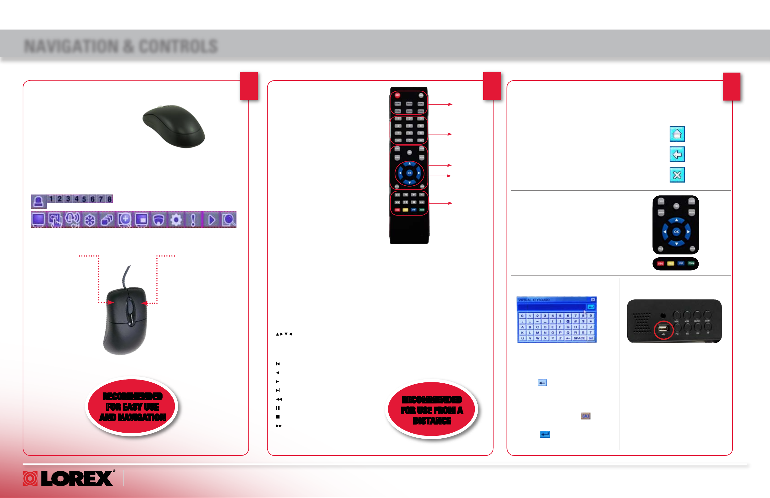
MOUSE:
This system has been designed to use
a PS/2 mouse control as its primary
methods of navigation and configuration.
Connect the included mouse to the
PS/2 port located on the rear panel
before powering on the system.
Once the unit has loaded, the mouse
will be recognized by the system.
LEFT BUTTON
CLICK:
• Select options and
change values in menus,
Recording mode, and
Search mode
• Operate controls in PTZ
mode
DOUBLE-CLICK:
• Double-click on a channel
in Quad or split-screen view
to view the channel in fullscreen.
RECOMMENDED
FOR EASY USE
AND NAVIGATION
RIGHT BUTTON
RIGHT CLICK:
• Switch between
active camera channels in full-screen
mode, or switch
between groups of
channels in Quad or
split-screen views
1
REMOTE CONTROL:
The Remote Control can also be used as a
primary mode of navigation and configuration.
Listed below is a quick reference of buttons
and their functions.
Group 1
REC: Press REC to start Panic recording on
the DVR
MENU: Press to open the System Main
Menu.
DVR 1- 6: Select DVR ID for controlling
multiple systems.
Group 2
Numeric Keypad - + - : Press number but-
tons to cycle through individual channels in
full-screen mode; 0+0 = 10, 0+1 = 11, etc.
Press –,+ to cycle through display modes:
full-screen, quad, eight.
Group 3
FUNC: Opens and closes the Function
control bar.
SEARCH: Opens the search menu
ESC: Exits menus, functions; stops play-
back.
AUDIO: Switch audio inputs (Ch. 1~4) or
mute the internal speaker.
MODE: Change screen displays: full-screen,
Quad and Split-Screen views.
PTZ: Opens the PTZ menu
BACKUP: Opens the USB Backup menu
Group 4
, OK Navigation Buttons: Cycle
through menu options and change values.
Operate PTZ functions.
Group 5
Jump to start of recording
Reverse Playback
Play
Jump to end of recording
Rewind
Pause
Stop
Increase playback speed (2X, 4X,
8X,16X, 32X)
GROUP 1
GROUP 2
GROUP 3
GROUP 4
GROUP 5
SEC, FRZ, PIP, ZOOM -
SEQ: Automatically cycle channels in
sequence. Select full-screen, Quad, or
Eight-view prior to pressing SEQ.
FRZ: In full-screen mode, freeze image;
press Esc to cancel. In Quad and Eightview, activate freeze features, then press
corresponding numeric button to freeze
the image; press Esc to cancel.
PIP: Turn on picture-in-picture view.
ZOOM: Activate full-screen zoom mode.
Use navigation arrows to scan image;
press ESC to cancel.
RECOMMENDED
FOR USE FROM A
DISTANCE
2
USING THE NAVIGATION ICONS:
Use the Navigation Icons when navigating the
system menus.
• HOME Click the Home Icon while in any menu to
return to the System Main Menu.
• BACK Click the Back Icon to return to the previous
menu.
• EXIT Click the Exit Icon to exit menus.
USING THE NAVIGATION BUTTONS:
When using the remote control, the
Navigation Buttons are the primary
way to move through the system
menus.
VIRTUAL KEYBOARD CONTROL:
You need to use the Virtual Keyboard to change user passwords
and to edit camera names. (e.g.
Camera title, DDNS etc.)
1. Click to delete the default
password or camera title.
2. Enter a new password or
camera title using the alphanumeric keypad. Press to
change case.
3. Press to save changes and
close the Virtual Keyboard.
USB PORT:
USB 2.0 port for data backup and
uploading firmware updates
Upgrade Firmware:
Upgrade system firmware from a
USB flash drive.
USB Backup:
Archive recorded data from the
system by connecting an external
USB flash drive.
3
www.lorexcctv.com
L19WD Series Quick Start Guide_EN_R1 Page 2
Page 3
NAVIGATION & CONTROLS (CONTINUED)
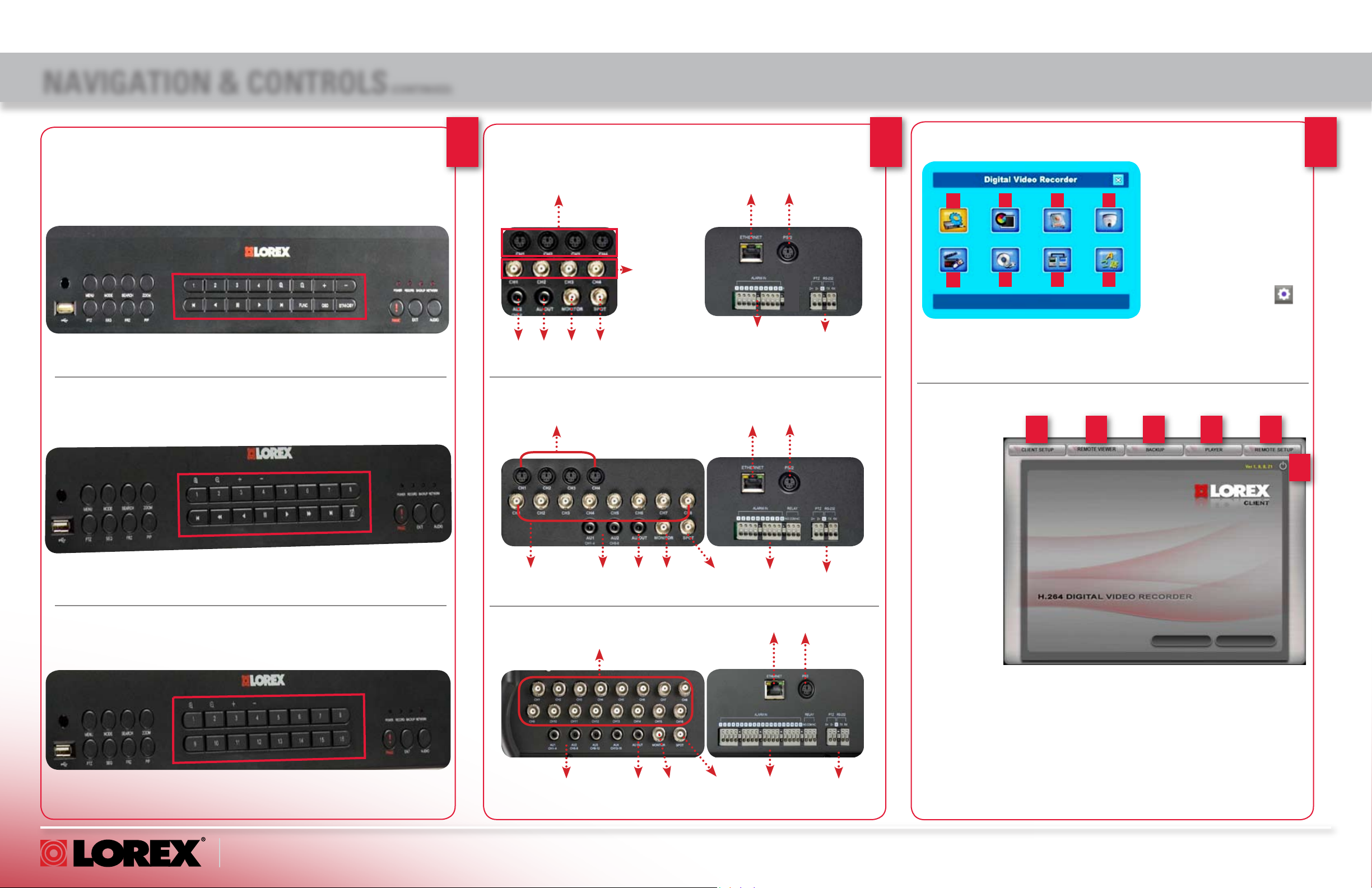
MONITOR FRONT PANELS:
4 CHANNEL
8 CHANNEL
8 CHANNEL
16 CHANNEL
4 CHANNEL
4
MONITOR BACK PANELS:
4 CHANNEL
DIN Camera Inputs
BNC Camera
Inputs
Audio
Audio
Monitor
Input
Out
8 CHANNEL
DIN Camera Inputs
BNC Camera
Inputs
16 CHANNEL
BNC Camera Inputs
Out
Spot
Out
Audio
Inputs
Audio
Out
Monitor
Out
Spot
Out
Ethernet
Alarm Block
Ethernet
Alarm
Block
Ethernet
PS/2
PS/2
PS/2
PTZ
PTZ
5
SYSTEM MAIN MENU:
1. CONFIGURATION
2. DISPLAY
3. HDD MANAGEMENT
1 2 3 4
5 6 7 8
4. CAMERA
5. RECORD
6. BACKUP/UPGRADE
7. NETWORK
8. LANGUAGE
To open the System Main Menu:
Mouse:
• From the Function Bar, click
Remote Control:
• Press MENU.
Note: You must login to the system
before you can access the System
Main Menu.
LOREX CLIENT SOFTWARE - MAIN MENU:
1 2 3 4 5
The Lorex
Client
software
allows you
perform
multiple
functions
from a
remote
location
over the
Internet or
local area
network
(LAN).
6
6
16 CHANNEL
www.lorexcctv.com
Audio
Inputs
Audio
Out
Monitor
Out
Spot
Out
Alarm
Block
PTZ
1. CLIENT SETUP – Configure the Client software to connect to your
system.
2. REMOTE VIEWER – View live video, search, and playback recorded data
on your System.
3. BACKUP – Backup recorded video from your system to your PC.
4. PLAYER – Playback recorded backup video data on your PC.
5. REMOTE SETUP – Change settings on your system remotely.
6. Power – Click to exit the program
L19WD Series Quick Start Guide_EN_R1 Page 3
Page 4
RECOMMENDED TIPS
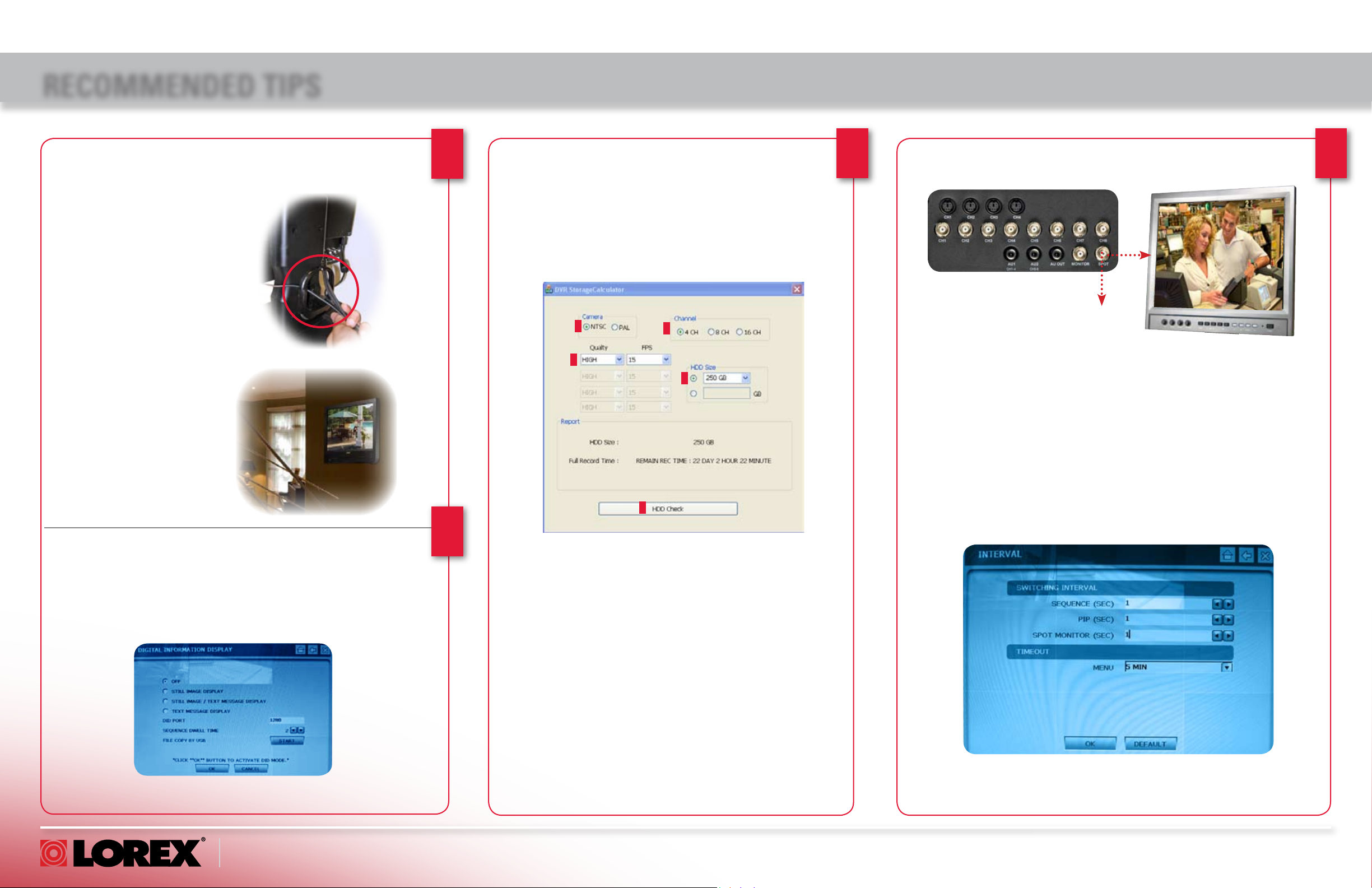
STAND WITH CABLE MANAGEMENT SOLUTION FOR
TIDIER INSTALLATION
Device Connections:
An add-on cable hook is
included with your system to
easily organize and conceal
wiring. Connect the Power
Cable, Cameras, Ethernet
Cable and any other optional
cables to the System by
running the cables through
the cable hook before
connecting to the Observation System.
WALL MOUNTABLE
VESA STANDARD
Your system can be
mounted on a wall using
a VESA standard mounting bracket (not included).
Simply unscrew the 4
screws to remove the
stand.
LOREX MESSAGE MASTER DID SOFTWARE SENDS
TEXT AND PICTURES FROM A REMOTE LOCATION
The Message Master Digital Information Display (DID) (included on
the software CD) allows you to show digital images and text on your
system. You can customize the text and images for advertising your
business, or as a screen saver.
Note: Prior to using the DID Client, make sure you have enabled
Lorex DDNS on your system.
1
4
STORAGE CALCULATOR
The Storage Calculator application is used to calculate the
amount of recording time available on your Hard Drive, based
on the System Recording Settings. This application is located
on the Software Installation CD (provided with your system).
Enter your specific settings and press the CALCULATE button.
The Software will calculate the estimated* recording time
(circled below).
2
3
4
5
6
TO USE THE STORAGE CALCULATOR:
1. Double-click Storage Calc.exe.
2. Under Camera, click the NTSC or PAL radio buttons.
3. Depending on your system, click the 4 CH, 8 CH, or 16 CH radio buttons.
4. Click the Quality drop-down menus to NORMAL, HIGH, or HIGHEST. Click the
FPS drop-down menus and select 3, 5, 10, 15, or 30 frames-per-second.
5. Click the HDD Size drop-down menu and select the hard disk size of your
system.
Note: If your hard drive size is not listed, click the radio button below the drop
down menu and enter your hard drive size manually.
6. Click HDD Check. The Storage Calculator displays record time available (day/
hour/minute) according to the entered values. Adjust the values
to find the best configuration to suit your security needs.
* Recording capacity may vary based on recording resolution
and quality, lighting conditions and movement in the scene.
2 3
CONNECTING A SPOT-OUT MONITOR
Spot Out
Use the Spot port on the rear panel of the system to connect a Spot
Out Monitor (not included). Spot Out displays the camera channels
in sequence. You can change the dwell time for the time interval in
the Interval menu. This is useful for a monitor in public view: you can
make people aware that they are being watched. You can also use
the spot-out monitor to display announcements or advertising.
CONNECTING AN EXTERNAL MONITOR
Use the Monitor port on the rear panel of the system to connect
an external monitor. Monitor-out mirrors the entire screen image of
your system. This is useful if you need to monitor the system from a
second location (e.g. a back office).
This feature is used for situations in which you want to have the
system in a back room while still displaying images to the public
eye, for deterrence or advertising purposes.
www.lorexcctv.com
L19WD Series Quick Start Guide_EN_R1 Page 4
Page 5

SET UP YOUR MONITOR FIRST
under 30 minutesunder 15 minutes under 60 minutes
Hand Tools Hardware
Router
Hi Speed
over 60 minutes
Skill Level
Time
under 30 minutesunder 15 minutes under 60 minutes
Hand Tools Hardware
Router
Hi Speed
over 60 minutes
BASIC INSTALLATION GUIDE
Time Tools Skills - Easy
STEP 1
1a
ATTENTION: The ends of the extension
cable are NOT the same - one end has
a Male power connector, and the other
has a Female power connector. Before
permanently running the Camera Extension Cable, make sure that the cable has
been oriented between the Camera and
the unit correctly.
Connect BNC Cameras to the Monitor:
IF YOU ARE USING BNC CAMERAS:
1. Connect the Extension cable to the Camera and system
• Connect the Female Barrel Power connector to a power adaptor.
• Connect the BNC connector to an available BNC port (CAM
1~4) on the system.
• Connect the Male Power connector to the Camera.
• Connect the BNC connector to the Camera.
2. Connect the Power Adaptor to a wall outlet.
Male Power Connector - The
male power connector end of the
Extension cable connects to the
Camera.
Female Power Connector
- The female power connector
(barrel) end of the Extension
cable connects to the Power
Adaptor.
2
3
Under 20 Minutes*
* Installation time may vary based on
application and camera cabling
Hand Tools Plug & Play connectors,
Connect the Ethernet Cable:
Connect one end of the Ethernet cable (for remote
monitoring) to one of the router’s (not included)
LAN ports and the other end to Monitor’s Network
Port located at the back of the Monitor. See picture
below showing a generic LAN/WAN connection.
LAN (LOCAL AREA NETWORK)
BACK OF THE ROUTER
TO YOUR COMPUTER
TO YOUR MONITOR
WAN (WIDE AREA NETWORK)
Connect the Mouse:
Connect the included mouse to the PS/2 port
located at the back panel of the system.
On screen set up
OPTIONAL
NOTE: You cannot connect BNC and DIN
cameras to the same channel simultaneously.
IF YOU ARE USING DIN CAMERAS:
Connect DIN Cameras to the Monitor:
1b
* Connect cameras to extension
cables by aligning the arrows.
TIP: Test the cameras prior to
selecting a permanent mounting
location by temporarily connecting
the Cameras and Cables to your
System.
Connect the first camera to the CH1 input. Follow the same steps
to connect the additional cameras.
www.lorexcctv.com
NOTE: The arrow mark on top of the
flat side of the camera and cable
connectors should face UP while
inserting to the Monitor.
4
Connect the Power Cable:
Connect one end of the power adaptor to the monitor and the other end to an electrical outlet. Note: The
system automatically powers on once connected to a
power source. By default, all connected cameras are set
to record in Continuous Mode when the system is first
powered on.
L19WD Series Quick Start Guide_EN_R1 Page 5
Page 6

SET UP YOUR MONITOR FIRST (CONTINUED)
under 30 minutesunder 15 minutes under 60 minutes
Hand Tools Hardware
Router
Hi Speed
over 60 minutes
Skill Level
Time
under 30 minutesunder 15 minutes under 60 minutes
Hand Tools Hardware
Router
Hi Speed
over 60 minutes
BASIC INSTALLATION GUIDE
Time Tools Skills - Easy
STEP 1
ATTENTION: When first logging
in to the system, keep ADMIN
as your user name and leave the
password field blank. See Using
the System Configuration section in
the User’s Manual for more details
on changing your password.
Login to the System
After the initial startup sequence, you will need to
5
login to the system. To login, leave the default user
as ADMIN. Leave the password field blank and click
OK. See Starting up the System in the User’s Manual
for more details.
Under 20 Minutes*
* Installation time may vary based on
application and camera cabling
Hand Tools Plug & Play connectors,
On screen set up
ATTENTION: You must set the
date and time prior to setting a
recording schedule on the system. See Using the System Record
section in the User’s Manual for
more details.
4
5
3
Setting the Date and Time
6
USING THE MOUSE:
1. From the System Main Menu, click .
2. From the Configuration menu click DATE/TIME.
3. Click +/- to change the DISPLAY FORMAT, TIME ZONE
and Date and Time for the system. Check the DST box to
enable Daylight Savings Time.
4. Click OK to save your settings or click DEFAULT to restore
factory defaults.
5. Click to exit.
Congratulations!
You have completed Step 1 successfully.
You can now view, record and playback
images on your monitor.
www.lorexcctv.com
L19WD Series Quick Start Guide_EN_R1 Page 6
Page 7

Router
Hi Speed
over 60 minutes
Hi Speed
over 60 minutes
LOCAL VIEWING INSTALLATION GUIDE
SET UP LOCAL VIEWING ON YOUR PC
STEP 2
*Your system MUST be connected to a Router prior to powering it ON.
192.168.1.12
NOTE: The system will lease networking information
from your Router. If you wish to set your information
manually, then remove the from DHCP option.
Please consult your Hardware Manual for further
Menu options.
THIS STEP RELATES TO REMOTE VIEWING OVER THE LAN (LOCAL AREA NETWORK)
BY USING A PC LOCATED ON THE SAME NETWORK AS THAT OF THE SYSTEM.
Retrieve System Information:
1
Press and hold the Enter button on the Front Panel for three seconds OR
1. Move the mouse cursor toward the bottom of the screen to open the
Function Bar and click .
2. From the System Main Menu, click Configuration and click
System Information.
Record the IP and MAC Addresses in the section below:
IP ADDRESS : . . .
MAC ADDRESS : : : : : :
(Required for DDNS registration)
If the IP Address is
127.0.0.1 it means
that you are either
not connected to
your local network or
your system is not in
DHCP detect mode.
3
4
Time Skills - Intermediate
Under 30 Minutes*
* Installation time may
vary based on application
Hardware
Computer &
Router*
* Minimum System Requirement:
Windows XP, Pentium IV, 256MB
Ram (512MB Recommended),
200MB Storage, High Speed
Internet, DSL or Cable Modem
Plug & Play connectors,
On screen set up
Lorex Client Software:
(on your local computer for local viewing):
Close the CD Menu Screen. A
Lorex Client icon will appear on
your desktop.
Run the Lorex Client Software:
(on your local computer for local viewing):
Double-click the Lorex Client
software icon on your desktop
to run the program.
Computer - not included
Install Software:
2
(on your local computer for local viewing):
Insert the Lorex Client Software CD into your
local computer’s CD ROM.
www.lorexcctv.com
Click Next and follow
the installation screens
to complete Lorex Client
Software installation.
5
Lorex Client Set-up:
(on your local computer for local viewing):
From the Lorex Client main window,
click Client Setup in the top-left
corner.
L19WD Series Quick Start Guide_EN_R1 Page 7
Page 8

SET UP LOCAL VIEWING ON YOUR PC (CONTINUED)
STEP 2
Register a Site:
6
7
1
Ofce
6
2
3
4
5
(on your local computer for local viewing):
8
From the Client Setup window, click Register
Site. A new window opens for you to input your
system’s network information.
Enter Client Setup Information:
(on your local computer for local viewing):
Under IP Setup:
1. Enter your System’s IP address (recorded in Step 2 - 1)
2. Enter the Monitor TCP/IP port ‘5000’ (by default)
3. In the Location field, enter a name for your system (i.e. Office).
4. Enter the User ID (ADMIN by default), max. 5 characters.
5. Enter the Admin Password (blank by default)
* User ID and Password are case sensitive
6. Once you see the registered site, press the OK button.
7. Select your newly added site and click OK
View Cameras Locally:
(on your local computer for local viewing)
From the Lorex Client main window, click
Remote Viewer.
On the Remote Viewer window, you
will see your system’s IP address, Port
number, and User ID already filled in the
text fields.
Enter your system’s password (blank by
default) and click the Connect button to
connect to Local Live Site to view your
cameras.
For complete information on using
the Remote Viewer, Player, and
Backup functions of the Lorex
Client, please refer to the Lorex
Client Software Users Guide.
7
*For viewing your system in your local area network (LAN)
LOCAL LIVE SITE*
Congratulations!
You have completed Step 2 successfully.
You can now view, playback images
and remotely control your system on
7
www.lorexcctv.com
L19WD Series Quick Start Guide_EN_R1 Page 8
your local computer over the Local Area
Network (LAN).
Page 9

REMOTE VIEWING INSTALLATION GUIDE
Hi Speed
over 60 minutes
Hi Speed
over 60 minutes
SET UP INTERNET REMOTE SECURITY MONITORING
STEP 3
Port forward your router first before proceeding with the set-up
You must forward Ports:
1
5000 (TCP/IP), 80 (WEB)
All routers are different. To port forward your router, please refer to your router’s
user manual.
A router configuration guide featuring the most commonly used routers in the market
is available on your Lorex Client Software CD and also on www.lorexcctv.com/support
in the Consumer’s Guide Section.
An example of a port forwarding screen is shown for illustration purposes.
EXAMPLE
VISIT WWW.LOREXCCTV.COM/SUPPORT
TO VIEW THE ROUTER CONFIGURATION
GUIDE
System
System
DDNS (Dynamic Domain Name System) Set-up:
5000 5000
80 80
12
12
1
2
3
Service Provider: dns1.lorexddns.net
Domain Name: tomsmith.lorexddns.net
User ID: tomsmith
Password: (your password)
Time Hardware
60 Minutes
* Installation time may vary
based on application
Complete New Account Information:
4
1. FOR PRODUCT LICENSE select the L19WD
Series option from the drop down menu.
2. FOR PRODUCT CODE enter the Monitor’s MAC
address (recorded in step 2, section 1).
3. FOR URL REQUEST enter a unique URL name
(e.g. tomsmith). Note: URL name should not be
more than 15 characters.
Registration Email:
An automated REGISTRATION CONFIRMATION
5
EMAIL will be sent to your email. Print and Save
this confirmation. You will need this information to
access your System remotely.
Computer &
Router*
* Minimum System Requirement:
Windows XP, Pentium IV, 256MB
Ram (512MB Recommended),
200MB Storage, High Speed
Internet, DSL or Cable Modem
Skills - Advanced
Basic Computer
Skills, Router Port
Forwarding
http://www.lorexddns.net
Open your web browser (Internet Explorer by default)
2
and enter http://www.lorexddns.net in the address bar.
LOREX PROVIDES A
FREE DDNS SERVICE
WITH THIS SYSTEM.
Create Account:
From the http://www.lorexddns.net website,
3
click the CREATE ACCOUNT option.
Create Account
Enter DDNS Set-up on your System:
1
2
3
6
Mouse navigation (recommended)
1. Using the Mouse, click on the Settings icon
to enter the System Main Menu. You will be
prompted to enter the User Name and Password.
2. Click on the Network icon.
3. Click on DDNS to enter the DDNS Menu.
www.lorexcctv.com
L19WD Series Quick Start Guide_EN_R1 Page 9
Page 10

SET UP INTERNET REMOTE SECURITY MONITORING (CONTINUED)
STEP 3
tomsmith
tomsmith
*****
Enable DDNS Settings:
7
On the DDNS Menu and in the
DDNS checkbox, put a mark to
enable DDNS.
Set the DDNS Settings:
1. DDNS Domain Name is ddns.lorexddns.net (by default)
8
2. Using the Virtual Keyboard enter the DOMAIN NAME sent to
you in the REGISTRATION CONFIRMATION EMAIL
(i.e.tomsmith.lorexddns.net).
4. Enter the User ID sent to you in the REGISTRATION CONFIRMATION EMAIL.
5. Enter your Password (from the DDNS Registration Email sent to
you - blank by default).
6. Click the OK button - a SUCCESS message will appear if the
settings are correct.
7. Click to exit.
10
11
Lorex Client Software:
(on your remote computer for remote viewing):
Close the CD Menu Screen. A
Lorex Client icon will appear on
your desktop.
Run the Lorex Client Software:
(on your remote computer for remote viewing):
Double-click the Lorex Client
software icon on your desktop
to run the program.
Computer - not included
Install Software:
(on your remote computer for remote viewing):
9
Insert the Lorex Client Software CD into your
local computer’s CD ROM.
www.lorexcctv.com
Click Next and follow
the installation screens
to complete Lorex Client
Software installation.
12
Lorex Client Set-up:
(on your remote computer for remote viewing):
From the Lorex Client main window,
click Client Setup in the top-left
corner.
L19WD Series Quick Start Guide_EN_R1 Page 10
Page 11

SET UP INTERNET REMOTE SECURITY MONITORING (CONTINUED)
STEP 3
tomsmithtomsmith.lorexddns.net
Office
Register a Site:
13
14
1
2
3
4
5
(on your remote computer for remote viewing):
From the Client Setup window, click Registering
Site. A new window opens for you to input your
network information.
Enter Client Setup Information:
(on your remote computer for remote viewing):
Under IP Setup:
1. Enter the DDNS Domain Name from the Registration
Email sent to you. (i.e tomsmith)
2. Enter the Monitor TCP/IP port ‘5000’ (by default)
3. In the Location field, enter a name for your system (i.e. Office).
4. Enter the User ID (ADMIN by default), max. 5 characters
5. Enter the Admin Password (blank by default)
16
15
View Cameras Locally:
(on your remote computer for remote viewing):
From the Lorex Client main window, click
Remote Viewer.
On the Remote Viewer window, you
will see your system’s IP address, Port
number, and User ID already filled in the
text fields.
Enter your system’s password (blank by
default) and click the Connect button to
connect to Remote Live Site to view your
cameras.
For complete information on using
the Remote Viewer, Player, and
Backup functions of the Lorex
Client, please refer to the Lorex
Client Software Users Guide.
6
* User ID and Password are case sensitive
6. Once you see the registered site, press the OK button
7. Select your newly added site and click OK
7
7
NOTE: The DDNS service supports Dynamic IP addresses for remote
connection. When this feature is configured on the remote system, you can
access it remotely using the domain name instead of IP address. To use this
feature, the system must be registered on the Lorex DDNS server.
Alternatively, if you have a static IP address you can enter it here.
Please refer to the LOREX CLIENT Manual for network setup and
configuration.
*For viewing your system from a remote location (Internet).
www.lorexcctv.com
REMOTE LIVE SITE*
Congratulations!
You have completed Step 3 successfully.
You can now view, playback images and
remotely control the system on your
Remote computer over the Internet.
L19WD Series Quick Start Guide_EN_R1 Page 11
Page 12

It’s all on the Web
www.lorexcctv.com
For detailed setup information, please refer to your User’s Manual. For additional
information about determining your IP address, configuring your router, and port
forwarding, please visit our website www.lorexcctv.com/support and click Consumer
Guides Section or view guides from the CD included with your system.
Email Support: support@lorexcorp.com
Toll Free Technical Support - North America: 1-888-42 LOREX (1-888-425-6739)
Toll Free Technical Support - International (outside of North America): +800-425-6739-0
(Example: From the UK, dial 00 instead of +)
Lorex International Website - www.lorexcctv.com
PROFESSIONAL RESIDENTIAL
COMMERCIAL
 Loading...