

Page 1

W W W . L O R E X C C T V . C O M
B US IN ES S & HO ME S EC UR IT Y
L19LD800 Series
QUICK START GUIDE R2
INFORMATION IN THIS DOCUMENT IS SUBJECT TO CHANGE WI THOUT NOTICE . AS OUR PRODUCTS ARE SUBJECT TO CONTINUOUS IMPROV EMENT,
LOREX TECHNOLOGY INC. AND OUR SUBSIDIARIES RESERVE THE RIGHT TO MODIF Y PRODUCT DESIGN, SPECIFICATIONS AND PRICES, WITHOUT
NOTICE AND WITHOUT INCURRING ANY OBLIGATION. E&OE © 2007 LOREX. A LL RIGHTS RESERV ED.
Page 2
PACKAGE CONTENTS AND
under 30 minutesunder 15 minutes under 60 minutes
Hand Tools Hardware
Router
Hi Speed
over 60 minutes
Skill Level
Time
under 30 minutesunder 15 minutes under 60 minutes
Hand Tools Hardware
Router
Hi Speed
over 60 minutes
Router
Hi Speed
over 60 minutes
Hi Speed
over 60 minutes
Hi Speed
over 60 minutes
Hi Speed
over 60 minutes
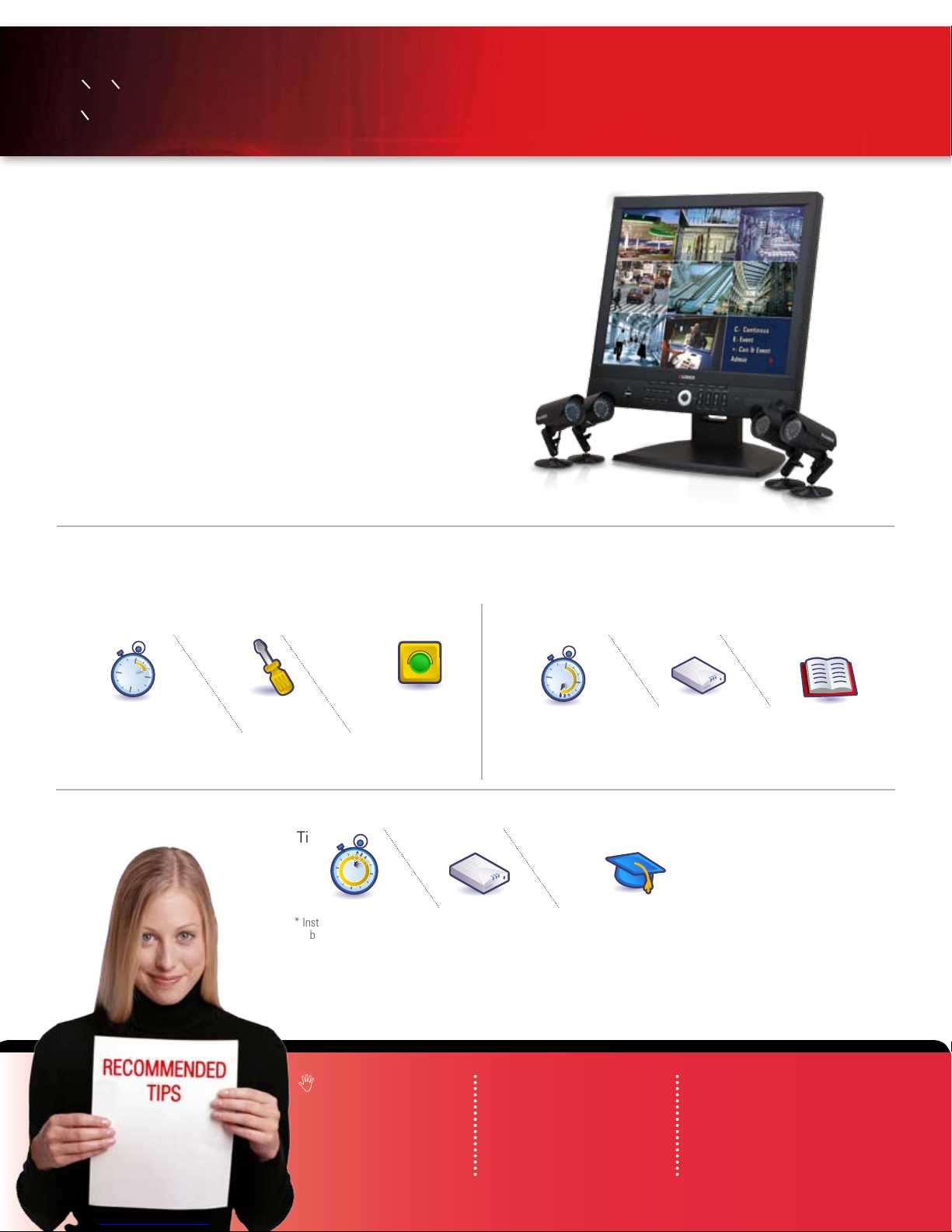
System Contents:
1 - 19” 8 Channel LCD Monitor with pre-installed HDD
4 - High Res. Color Cameras
4 - 100 ft (30M) Extension Cables
4 - Camera Stands with Mounting Screws
1 - 10 ft Ethernet Cable
1 - Remote Control
2 - AAA Batteries
1 - Power Adaptor (for monitor)
1 - Lorex Client Software CD
1 - User’s Manual
1 - Software Manual
1 - Quick Start Guide
* Camera configuration and HDD (hard disk drive) capacity may vary
by model. BNC Cameras require individual power adaptors. Check
your package for specific content information.
INSTALLATION GUIDE:
*
*
*
*
INSTALLATION GUIDE
STEP 1 STEP 2
Time Tools Skills - Easy
Under 20 Minutes*
* Installation time may vary based on
application and camera cabling
Hand Tools Plug & Play connectors,
STEP 3
Time Hardware
* Installation time may vary
based on application
ATTENTION:
Check Pages
www.lorexcctv.com
Broadband Router
14 - 15
On screen set up
60 Minutes
* Minimum System Requirement: Windows XP, Pentium IV,
256MB Ram (512MB Recommended), 200MB Storage, High
Speed Internet, DSL or Cable Modem
and Computers are
required for local and
remote monitoring
(not included).
Time Skills - Intermediate
Under 30 Minutes*
* Installation time may
vary based on application
Skills - Advanced
Computer &
Router*
INSTRUCTIONS:
For detailed setup
information, please
refer to your User’s
manual.
Hardware
Basic Computer
Skills, Router Port
Forwarding
Computer &
Router*
Plug & Play connectors,
On screen set up
SOFTWARE
REQUIREMENTS:
For Lorex Client 3.0
Software requirements,
L19LD800 SERIES QSG_EN_R2
please refer to the
Software User’s manual.
Page: 2
Page 3
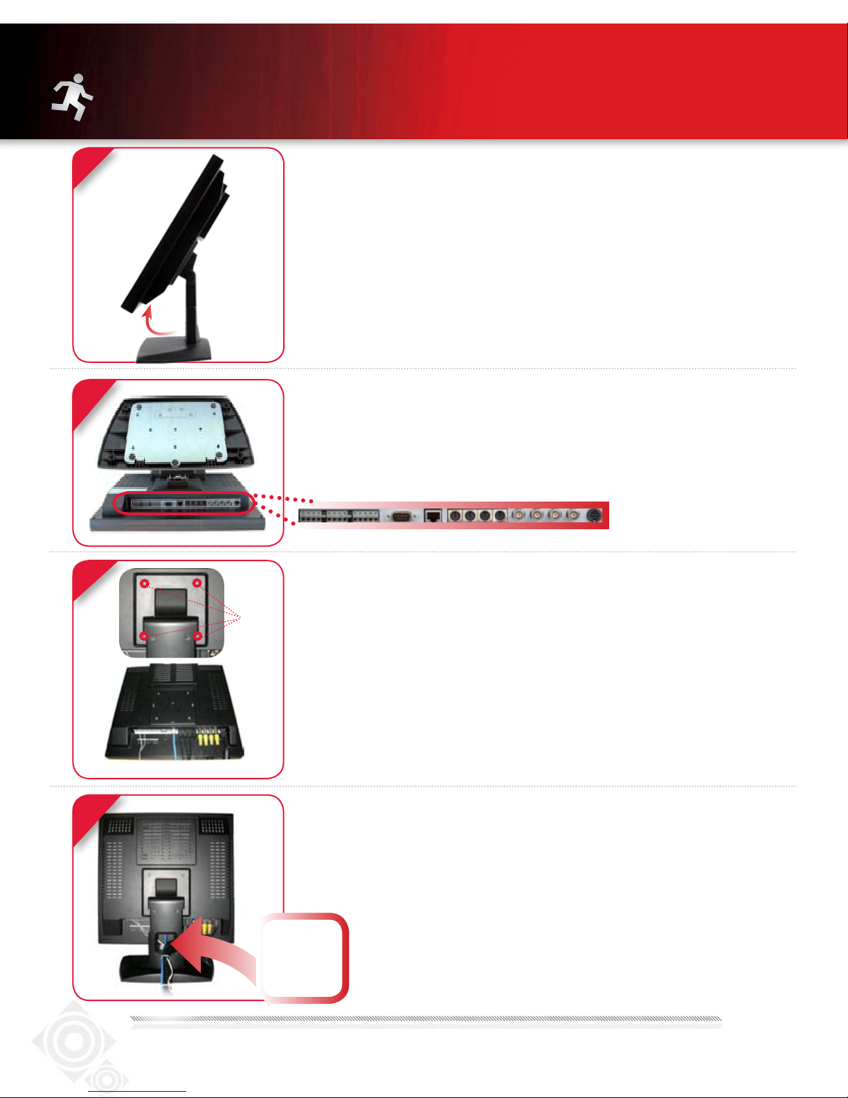
STEP 1 - SET UP YOUR MONITOR FIRST
1
2
TILT MONITOR
Tilt the monitor (40˚) to allow for easier access to the
connectors.
OPTIONAL - LOCATE MONITOR CONNECTIONS
Lay the monitor facing down on a soft surface. Make sure
to protect the screen from sharp objects.
2a
DEVICE CONNECTIONS (Stand Removed)
3
Screws
Efficient back
panel provides
a solution for
neat cable
management.
OPTIONAL - REMOVE MONITOR STAND
The system has an efficient back panel control that
provides a cable management solution.
By design the connectors are not easily accessible, in
order to secure the connections.
It is recommended to remove the stand for initial set-up
by simpy unscrewing four screws with a standard screw
driver.
DEVICE CONNECTIONS
The stand comes with a built in cable channel to easily organize
and conceal wiring. Connect the Power Cable, Cameras, Ethernet
Cable and any Alarm Devices to the System by running the cables
through the hole in the stand before connecting to the
Observation System.
NOTE: Your system can be mounted on a wall using a VESA
standard mounting bracket (not included).
www.lorexcctv.com
L19LD800 SERIES QSG_EN_R2
Page 4
STEP 1 - SET UP YOUR MONITOR FIRST
CONTINUED
4
4a
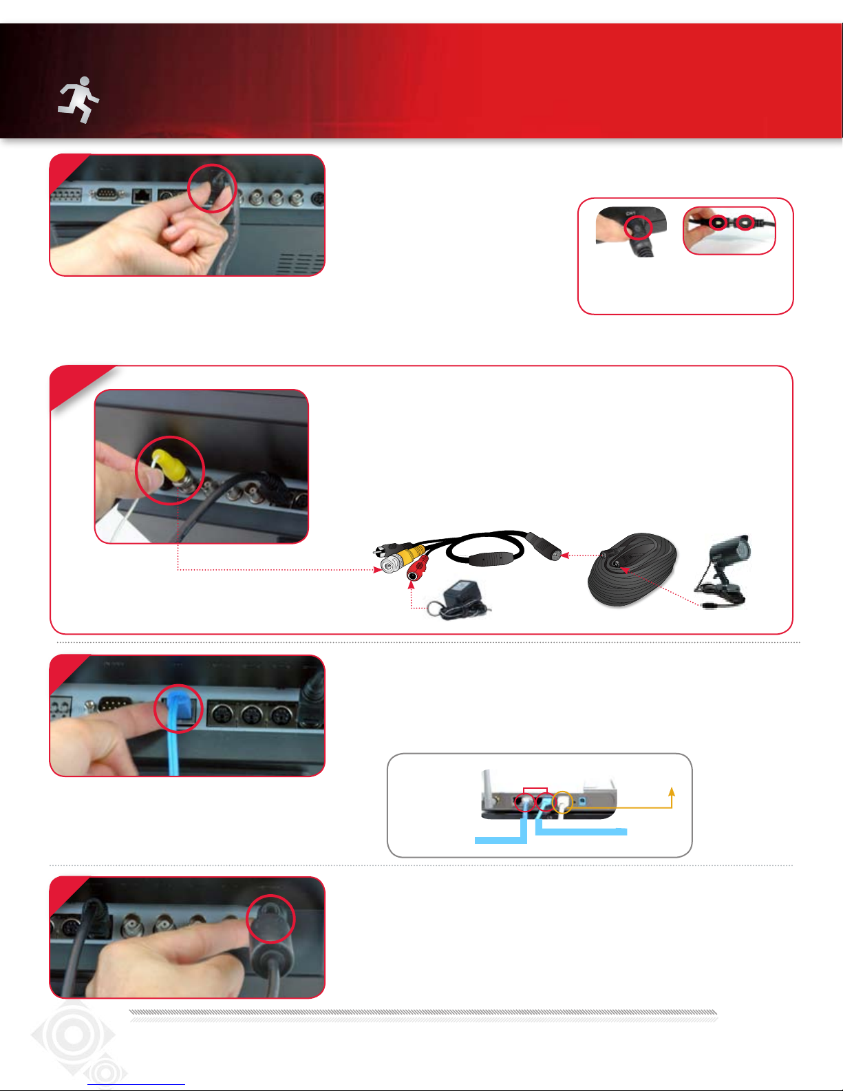
CONNECT CAMERAS TO THE MONITOR
Your system includes 4 high resolution 6 PIN DIN cameras.
* Connect cameras to extension cables
by aligning the arrows. Plug in cameras
and cables before mounting the cameras.
TIP: Test the cameras prior to selecting
a permanent mounting location by
temporarily connecting the Cameras
and Cables to your System.
NOTE: The arrow mark on top of the flat side of
the camera and cable connectors should face
UP while inserting to the Monitor.
Connect the first camera to the CH1 input. Follow the same steps to
connect the additional cameras.
OPTIONAL
You can connect 4 additional (BNC) Cameras using the BNC ports.
With the use of a Universal DIN to BNC Cable you can connect 4 additional 6
PIN DIN Cameras to your monitor.
Note: BNC cameras require separate power adaptors. The SG7610B Camera
Kit includes an individual Power Adaptor and an Universal DIN to BNC Cable.
5
6
UNIvERSAL DIN TO BNC CABLE
CONNECT ETHERNET CABLE
Connect one end of the ethernet cable to one of the router’s (not
included) LAN PORTS and the other end to the Monitor’s Network Port
located at the bottom of the monitor. See picture below showing a
generic LAN/WAN connection.
LAN (LOCAL AREA NETWORK)
BACK OF THE ROUTER SHOWN
TO YOUR COMPUTER
WAN (WIDE
AREA NETWORK)
TO YOUR MONITOR
CONNECT POWER CABLE
Connect one end of the Power adaptor to the monitor, the other end
to an electrical outlet. This unit powers ON once it is plugged in to the
power outlet.
TIP: Once you are done with the connections, remember to screw the
stand back on.
www.lorexcctv.com
Page: 4
L19LD800 SERIES QSG_EN_R2
Page 5
DATE / TIME SETUP
SETUP
FORMAT
DATE 2007/09/16
TIME 19:08:13
TIME ZON E (GMT-05:00) Ea stern Time
DST OFF
DATE YYYY/MM/D D
TIME 24H
INTER VAL OFF
SERVE R
TIME SY NC
SYNC
STEP 1 - SET UP YOUR MONITOR FIRST
CONTINUED
7
a
b
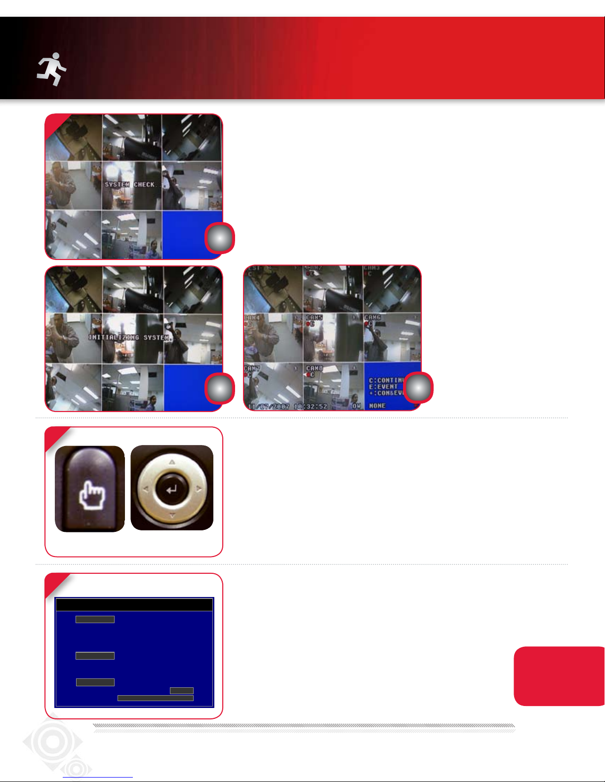
INITIAL LOADING SEQUENCE
The unit will automatically begin loading when power is connected to
the system.
a. During the loading sequence, the System will perform a Hard Drive and
Firmware check and the screen will display the text message
CHECK”.
b. Once the system checks are completed, the screen will display the text
message “INITIALIZING SYSTEM” before completing the loading process.
c. The unit will initially load to a split screen view, displaying all 8 cameras
(if available) and a system legend in a 3x3 Screen View.
NOTE: This may take up to 60
seconds. Please wait until the
system completes loading.
c
“SYSTEM
8
MENU
NAVIGATION &
ENTER
9
www.lorexcctv.com
MENU NAVIGATION CONTROLS
• MENU Button – Accesses the setup menu, and returns to previous
menu options.
• Navigation Controls - Move Up/Down/Left/Right.
• Enter Button - Press this button to select and change the values in a
menu option.
SET THE DATE & TIME
Click the MENU button on the front panel of the Monitor (or the
Remote Controller) to enter the Main Menu. From the Main Menu
move to SYSTEM and press the ENTER button to go to the DATE/TIME
menu to activate menu options.
NOTE: After you see all four (4) camera images
on your monitor screen, remove the protective
film from camera(s) and monitor screen.
Congratulations! You have completed Step 1
successfully. You can now view, record and
playback images on your monitor.
L19LD800 SERIES QSG_EN_R2
Make sure that
the Date and Time
are set prior to
recording.
Page 6

SYSTEM INFOR MATION
SYSTEM NAME MYS YSTEM
SYSTEM ID 01
S/W VER SION 1.1.0.8
VIDE O TYPE NTSC
DDN S NA ME
NETW ORK P ORT 3000
WEB PORT 80
IP A DDR ESS 192.168.0.104
MAC ADD RESS 01:23:45:67:89: AB
DISK CA PACI TY 120GB / 320GB
DISK TEMPE RATU RE 100F (GOOD )
STEP 2 - SET UP LOCAL VIEWING ON YOUR PC
THIS STEP RELATES TO REMOTE VIEWING OVER THE LAN (LOCAL AREA NETWORK) BY USING A
PC LOCATED ON THE SAME NETWORK AS THAT OF THE SYSTEM.
*YOUR OBSERVATION SYSTEM MUST BE CONNECTED TO A ROUTER PRIOR TO POWERING IT ON.
1
RETRIEVE SYSTEM INFORMATION
To retrieve the System Information, press the ENTER button on the front
panel of the Monitor or the Remote Control.
RECORD THE IP AND MAC ADDRESSES IN THE SECTION BELOW
IP ADDRESS: . . .
MAC ADDRESS:
(Required for DDNS registration)
NOTE: The system will lease
networking information from
your Router. If you wish to set
your information manually,
then set the DHCP MODE to
MANUAL. Please consult your
Hardware Manual for further
Menu options.
2
Computer - not included
www.lorexcctv.com
INSTALL SOFTWARE
(on your local computer)
Insert the Lorex Client 3.0 Software CD into your local computer’s CD ROM
drive and proceed with the installation.
Page: 6
L19LD800 SERIES QSG_EN_R2
Page 7

3
STEP 2 - SET UP LOCAL VIEWING ON YOUR PC
CONTINUED
LOREX CLIENT 3.0 SOFTWARE
Follow the installation screens to complete Lorex Client 3.0
Software installation.
4
RUN LOREX CLIENT 3.0 SOFTWARE
(on your local computer)
Lorex Client and LorexPlayer icons will appear on your desktop.
Double-click the Lorex Client icon on your desktop to run the program.
The log-in window may appear before the main program window loads.
LorexClient LorexPlayer
Enter your password to start the program.
NOTE: Initial password is blank
TIP: When you run LorexClient on Windows XP operating system, you
will see the Windows Security Alert. Please click unblock to run the
application.
Please refer to your Lorex Client 3.0 Software Manual for instructions
about using Lorex Backup Player and Storage Calculator.
5
www.lorexcctv.com
ADD A LOCAL SITE:
(on your local computer)
Click the Menu button and select the NEW item.
L19LD800 SERIES QSG_EN_R2
Page 8

STEP 2 - SET UP LOCAL VIEWING ON YOUR PC
CONTINUED
6
7
Ofce
ENTER SETUP INFORMATION
(on your local computer)
Enter a name and site information for the remote site.
1
2
3
4
1. Enter a Name of the site (e.g. Office)
2. Enter the User ID (admin by default)
3. Enter the User Password (blank by default)
4. Enter the DVR/Monitor TCP/IP port (3000 by default)
5. Enter the IP Address recorded in Step 2-1
6. Click Add to add the remote site
7. Click EXIT
5
6
7
CONNECTION
(on your local computer)
Highlight the site you set-up in Step 2-6. Click the Connect
button and select the Connect item to connect the remote
site.
8
8
www.lorexcctv.com
LOCAL LIVE SCREEN
(on your local computer)
Congratulations! You have completed Step 2 successfully.
You can now view, playback images and remotely control
your system on your local computer over the Local Area
Network (LAN).
Page: 8
L19LD800 SERIES QSG_EN_R2
Page 9

STEP 3 - SET UP INTERNET REMOTE
MONITORING
1
2
Router - not included
http://ddns.strategicvista.net
PORT FORWARD YOUR ROUTER
Port forward your router first before proceeding with the set-up
(ports 80, 3000, 3001, 3002, 3003).
All routers are different. To port forward your router, please refer to
your router’s user manual.
A router configuration guide is available on your Lorex Client Software
CD and also on www.lorexcctv.com/support in the Consumer’s
Guide Section.
DDNS SET-UP
Open your web browser (Internet Explorer by default)
and enter
http://ddns.strategicvista.net
in the address bar.
3
www.lorexcctv.com
CREATE ACCOUNT
From the http://ddns.strategicvista.net website, click the
CREATE ACCOUNT option.
L19LD800 SERIES QSG_EN_R2
Page 10

STEP 3 - SET UP INTERNET REMOTE
MONITORING
4
1
3
2
5
Service Provider: dns1.strategicvista.net
Domain Name: myurl.strategicvista.net
User ID: tomsmith1
Password: (your password)
CONTINUED
COMPLETE NEW ACCOUNT INFORMATION
1. FOR PRODUCT LICENSE select the L19LD800 Series option
from the drop down menu.
2. FOR PRODUCT CODE enter the Monitor’s MAC address
(recorded in step 2-1).
3. FOR URL REQUEST enter a unique URL name
(e.g. myurl). NOTE: URL name should not be more than
15 characters.
REGISTRATION EMAIL
An automated REGISTRATION CONFIRMATION EMAIL will
be sent to your email. Print and Save this confirmation. You
will need this information to access your System remotely.
6
7
ENTER DDNS SET-UP ON YOUR MONITOR
Once the DDNS settings have been configured online,
the information must be entered on the System to
allow for remote connection via the Lorex Software (or
through Internet Explorer).
Access the Main Menu Setup screens by pressing the
MENU key on the front panel of your monitor (or Remote
control) and navigate to the NETWORK option and press
ENTER. On the NETWORK SETUP screen scroll down
and select DDNS. Press the ENTER button to access the
DDNS network settings.
ENABLE DDNS SETTINGS
On the DDNS SETUP menu, enable DDNS by setting
ON/OFF to ON.
www.lorexcctv.com
Page: 10
L19LD800 SERIES QSG_EN_R2
Page 11

STEP 3 - SET UP INTERNET REMOTE
8
9
MONITORING
CONTINUED
VIRTUAL KEYBOARD CONTROL
The Virtual Keyboard control becomes Available
when keyboard input (A~Z, 0~9) is needed for entering
information such as Names, Network Information, etc.
• Navigate using the arrow keys on the Front Panel or by
using the Remote Control or a mouse.
• Use the ENTER key to choose the letters and numbers.
• Select the OK button once the setup is completed.
SET THE DDNS SETTINGS
NOTE: Use arrow keys to move to each item. Press Enter key to
select and change settings.
10
Enter the DOMAIN NAME sent to you in the REGISTRATION
CONFIRMATION EMAIL (i.e. myurl.strategicvista.net) leaving out
the .strategicvista.net part of the URL.
Enter the USER NAME (e.g. tomsmith1) sent to you in the
REGISTRATION CONFIRMATION EMAIL.
Enter your PASSWORD (blank by default).
Click the CHECK button – DDNS STATUS GOOD message will
appear if the settings are correct.
Press the MENU key to save your settings and exit.
INSTALL SOFTWARE
(on your remote computer for viewing your system from a remote location)
Insert the Lorex Client 3.0 Software CD into your remote computer’s
CD ROM drive and proceed with the installation.
Computer - not included
www.lorexcctv.com
L19LD800 SERIES QSG_EN_R2
Page 12

STEP 3 - SET UP INTERNET REMOTE
11
12
MONITORING
LorexClient LorexPlayer
CONTINUED
LOREX CLIENT 3.0 SOFTWARE
(on your remote computer)
Follow the installation screens to complete Lorex Client 3.0
Software installation.
RUN THE LOREX CLIENT 3.0 SOFTWARE
(on your remote computer)
Lorex Client and LorexPlayer icons will appear on your desktop.
Double-click the Lorex Client icon on your desktop to run the program.
The log-in window may appear before the main program window loads.
Enter your password to start the program.
13
NOTE: Initial password is blank
TIP: When you run LorexClient on Windows XP operating system, you
will see the Windows Security Alert. Please click unblock to run the
application.
Please refer to your Lorex Client 3.0 Software Manual for instructions
about using Lorex Backup Player and Storage Calculator.
ADD A REMOTE SITE
(on your remote computer)
Click the Menu button and select the NEW item.
www.lorexcctv.com
Page: 12
L19LD800 SERIES QSG_EN_R2
Page 13

STEP 3 - SET UP INTERNET REMOTE
14
MONITORING
Ofce
1
2
3
4
myurl
5
6
7
CONTINUED
ENTER SETUP INFORMATION
(on your remote computer)
Enter a name and site information for the remote site.
1. Enter a Name of the site (e.g. Office)
2. Enter the User ID (admin by default)
3. Enter the User Password (blank by default)
4. Enter the DVR/Monitor TCP/IP port (3000 by default)
5. Enter the DOMAIN NAME sent to you in the
REGISTRATION CONFIRMATION EMAIL
(e.g. myurl.strategicvista.net) leaving out the
.strategicvista.net part of the URL.
6. Click Add to add the remote site
7. Click EXIT
NOTE: The DDNS service supports Dynamic IP addresses for
remote connection. When this feature is configured on the remote
system, you can access it remotely using the domain name instead
of IP address. To use this feature, the system should be registered
on the Lorex DDNS server.
Alternatively, if you have a static IP address you can enter it here.
15
Live View
Please refer to the LOREX CLIENT Manual for network setup and
configuration.
CONNECTION
(on your remote computer)
Select the site you want to connect to from the Remote Site list,
and then click the Connect button to initiate connection. Once
connected, you will see images from the remote system.
www.lorexcctv.com
Congratulations! You have completed Step 3 successfully.
You can now view, playback images and remotely control
the system on your Remote computer over the Internet.
L19LD800 SERIES QSG_EN_R2
Page 14

RECOMMENDED TIPS
CONNECTING A MOUSE
Connect a mouse to one of the USB ports located on the front
of the unit. The mouse behaves in the same way as a PC mouse
- using Left Click, Right Click and Center Wheel. For detailed
information, please check the System User’s Manual.
NOTE: A three button mouse is required for the full
range of mouse functionality to be available.
LEFT CLICK
CENTER WHEEL
RIGHT CLICK
REMOTE CONNECTION USING A MOUSE DRAG &
DROP IN LOREX CLIENT SOFTWARE
Select a previously configured location from the “Remote
Site” window, and simply drag it to the location of live viewing (camera display) portion of the screen. All cameras from
the remote system will be displayed. You can also drag specific cameras to any available square in the Live View area,
as shown in the picture.
The software has an advanced feature which allows you to
connect to multiple sites and view cameras from different
locations simultaneously on one screen (maximum of 16
cameras). Simply drag the specific cameras from each site
you wish to connect to into the live viewing area.
HDD INSTALLATION
The System comes with a pre-installed Hard Drive, however
the unit will work with a replacement single Hard Drive (up to
750GB).
Pre-installed
HDD
www.lorexcctv.com
NOTE: Make sure that the System is OFF and the power cable has been
disconnected before changing the Hard Drive. For detailed instructions,
check your user’s manual included with the system.
SETTING THE NEW DRIVE TO MASTER:
• Refer to the General Jumper Pin Setting on HDD Surface (generally
located on a sticker on the top of the drive).
• Set the Jumper Pin Set to Master (1 Drive). NOTE: Use a Hard Drive
Model with a power supply rated UDMA66 or higher.
CONNECTING THE IDE CABLE:
• Confirm the IDE Cable is securely connected within the System.
FORMATTING THE NEW HARD DRIVE:
The New Hard Drive MUST be formatted. If a new HARD DRIVE is
detected, the system will prompt you to FORMAT the drive.
Page: 14
L19LD800 SERIES QSG_EN_R2
Page 15

RECOMMENDED TIPS CONTINUED
MONITOR POWER SAVING TIP
To extend the life of your monitor, it is highly recommended
that you take advantage of the AUTO BRIGHTNESS &
MAIN DISPLAY OFF features. Enabling these features will
save power by automatically dimming your monitor when
not in use or turning the monitor OFF during off-peak hours
(NOTE: recording will not be turned OFF or affected by
these settings). Follow these simple instructions to extend
the life of your monitor.
SYSTEM SET-UP MENU
2
Enter SYSTEM menu on your monitor by pressing the
MENU key on the front panel of your monitor (or Remote
Control). Scroll down to SCREEN SAVE and press ENTER.
1
SCREEN SAVE MENU
On the SCREEN SAVE menu, use arrow
key to move to each item. Press Enter
key to select and change.
1. Enable Screen Saver by setting ON/
OFF item to ON.
2. Select TYPE (TIME or AUTO):
TIME causes the system to turn on the
power of screen once the time is
same as the value in the SCREEN ON
field and turn off the power of screen
once the time is same as the value in
the SCREEN OFF field.
AUTO causes it to turn off the power of screen
once there isn’t any user operation in the system for TIME OUT. The TIME OUT options are:
1 MIN, 5 MIN, 10 MIN, 30 MIN, and 1 HOUR.
3. Enter Time Period:
In case that the TYPE is TIME, enter time in the
SCREEN OFF field to determine the time you
want the Main Display OFF.
NOTE: In case of TIME, you can turn on the
power of screen by pressing the POWER key on
the front panel while the Screen Save mode.
4. Select AUTO TIME OUT
In case that the TYPE is AUTO, select an item
in the TIME OUT field to determine the timeout
you want the Main Display OFF.
NOTE: In case of AUTO, the system turns on the
power of screen by detecting any user operation while the power saving mode.
5. Press MENU key to save settings and exit
menu.
www.lorexcctv.com
L19LD800 SERIES QSG_EN_R2
Page 16

PRODUCT SUPPORT
It’s all on the Web
www.lorexcctv.com
For detailed setup information, please refer to your User’s Manual. For additional
information about determining your IP address, configuring your router, and
port forwarding, please visit our website www.lorexcctv.com/support and click
Consumer Guides Section or view guides from the CD included with your system.
Email Support: support@lorexcorp.com
Toll Free Technical Support - North America: 1-888-42 LOREX (1-888-425-6739)
Toll Free Technical Support - International (outside of North America): 00-800-425-6739-0
Lorex International Website - www.lorexinternational.com
www.lorexcctv.com
PRODUCT SUPPORT
Specification Sheet
User’s Manual
Lorex Client Software Manual
Quick Start Guide
Port forwarding Guide
Basics of Remote Video
Access Guide
Page: 16
L19LD800 SERIES QSG_EN_R2
 Loading...