

Page 1
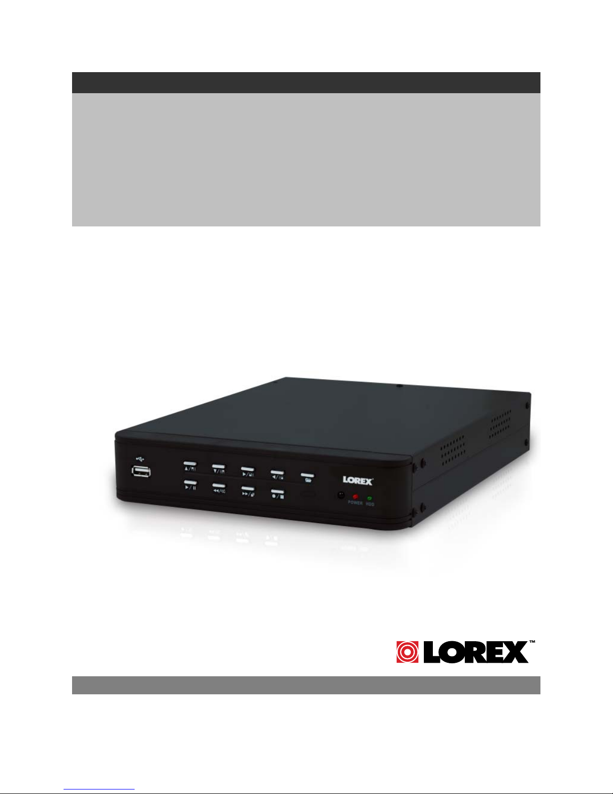
SURVEILLANCE DVR
WITH MOTION DETECTION
AND AUDIO RECORDING
Instruction Manual
4 CHANNEL
English Version 3.0
MODELS:
L104 & L104V Series
Includes L104000, L104161, L104251, L104V000, L104V161 & L104V251
Copyright © 2007 Lorex Technology Inc.
www.lorexcctv.com
Page 2
p
Thank you for purchasing the 4 Channel Surveillance DVR (with Motion Detection and Audio
Recording). Lorex is committed to providing our customers with a high quality, reliable security
product.
The L104 series offers excellent performance at a value price. This small form (9x12x2”) Surveillance
DVR provides real time recording in quad mode, single channel audio recording and motion detection
– scheduled – continuous mode recording. The L104 also has a remote controller and password
protection. In addition the L104 ‘V’ model provides optional VGA output for display on PC monitors.
To learn more about the 4 Channel Surveillance DVR (with Motion Detection and Audio Recording),
and to learn about our complete range of accessory products, please visit our website at:
http://www.lorexcctv.com
CAUTION
RISK OF ELECTRIC SHOCK
DO NOT OPEN
CAUTION: TO REDUCE THE RICK OF ELECTRIC SHOCK
REFER SERVICING TO QUALIFIED SERVICE PERSONNEL.
WARNING: TO PREVENT FIRE OR SHOCK HAZARD, DO NOT
EXPOSE THIS UNIT TO RAIN OR MOISTURE.
CAUTION: TO PREVENT ELECTRIC SHOCK, MATCH WIDE BLADE
OF THE PLUG TO THE WIDE SLOT AND FULLY INSERT.
DO NOT REMOVE COVER (OR BACK).
NO USER SERVICABLE PARTS INSIDE.
The lightning flash with arrowhead symbol, within an
equilateral triangle, is intended to alert the user to the
presence of uninsulated “dangerous voltage” within the
products ‘ enclosure that may be of sufficient magnitude
to constitute a risk of electric shock
The exclamation point within an equilateral triangle is
intended to alert the user to the presence of important
operating and maintenance (servicing) instructions in the
literature accompanying the appliance.
Please visit us on the web for the most current Manuals, Quick Start Guides and Firmware.
Additional Language Manuals are also available at:
2
://www.lorexcctv.com
htt
Page 3
p
Important Safeguards
Important Safeguards
In addition to the careful attention devoted to quality standards in the manufacture process of your video
product, safety is a major factor in the design of every instrument. However, safety is your responsibility
too. This sheet lists important information that will help to assure your enjoyment and proper use of the
video product and accessory equipment. Please read them carefully before operating and using your
video product.
Installation
1. Read and Follow Instructions - All the
safety and operating instructions should be
read before the video product is operated.
Follow all operating instructions.
2. Retain Instructions - The safety and
operating instructions should be retained for
future reference.
3. Heed Warnings - Comply with all warnings
on the video product and in the operating
instructions.
4. Polarization - Do not defeat the safety
purpose of the polarized or grounding-type
plug.
o A polarized plug has two blades with
one wider than the other.
o A grounding type plug has two
blades and a third grounding prong.
o The wide blade or the third prong is
provided for your safety.
o If the provided plug does not fit into
your outlet, consult an electrician for
lacement of the obsolete outlet
re
5. Power Sources - This video product should
be operated only from the type of power
source indicated on the marking label. If you
are not sure of the type of power supply to
your location, consult your video dealer or
local power company. For video products
intended to operate from battery power, or
other sources, refer to the operating
instructions.
6. Overloading - Do not overload wall outlets of
extension cords as this can result in the risk
of fire or electric shock. Overloaded AC
outlets, extension cords, frayed power cords,
damaged or cracked wire insulation, and
broken plugs are dangerous. They may result
in a shock or fire hazard. Periodically examine
the cord, and if its appearance indicates
damage or deteriorated insulation, have it
replaced by your service technician.
7. Power-Cord Protection - Power supply
cords should be routed so that they are not
likely to be walked on or pinched by items
placed upon or against them, paying
particular attention to cords at plugs,
convenience receptacles, and the point where
they exit from the video product.
8. Ventilation - Slots and openings in the case
are provided for ventilation to ensure reliable
operation of the video product and to protect
it from overheating. These openings must not
be blocked or covered. The openings should
never be blocked by placing the video
equipment on a bed, sofa, rug, or other
similar surface. This video product should
never be placed near or over a radiator or
heat register. This video product should not
be placed in a built-in installation such as a
bookcase or rack unless proper ventilation is
provided or the video product manufacturer’s
instructions have been followed.
9. Attachments - Do not use attachments
unless recommended by the video product
manufacturer as they may cause a hazard.
10. Water and Moisture - Do not use this video
product near water. For example, near a bath
tub, wash bowl, kitchen sink or laundry tub, in
a wet basement, near a swimming pool and
the like.
Caution: Maintain electrical safety. Power line
operated equipment or accessories
connected to this unit should bear the UL
listing mark of CSA certification mark on the
accessory itself and should not be modified
so as to defeat the safety features. This will
help avoid any potential hazard from electrical
shock or fire. If in doubt, contact qualified
service personnel.
11. Accessories - Do not place this video
equipment on an unstable cart, stand, tripod,
or table.
The video equipment may fall,
causing serious damage to the
video product. Use this video
product only with a cart, stand,
tripod, bracket, or table
recommended by the
manufacturer or sold with the
video product.
Any mounting of the product should follow
the manufacturer’s instructions and use a
mounting accessory recommended by the
manufacturer.
3
Page 4

Important Safeguards
Service
13. Servicing - Do not attempt to service this
video equipment yourself as opening or
removing covers may expose you to
dangerous voltage or other hazards. Refer all
servicing to qualified service personnel.
14. Conditions Requiring Service - Unplug this
video product from the wall outlet and refer
servicing to qualified service personnel under
the following conditions.
A. When the power supply cord or plug is
damaged.
B. If liquid has been spilled or objects have
fallen into the video product.
C. If the video product has been exposed to
rain or water.
D. If the video product does not operate
normally by following the operating
instructions. Adjust only those controls
that are covered by the operating
instructions. Improper adjustment of
other controls may result in damage and
will often require extensive work by a
qualified technician to restore the video
product to its normal operation.
E. If the video product has been dropped or
the cabinet has been damaged.
F. When the video product exhibits a
distinct change in performance. This
indicates a need for service.
15. Replacement Parts - When replacement
parts are required, have the service
technician verify that the replacements used
have the same safety characteristics as the
original parts. Use of replacements specified
by the video product manufacturer can
prevent fire, electric shock or other hazards.
16. Safety Check - Upon completion of any
service or repairs to this video product, ask
the service technician to perform safety
checks recommended by the manufacturer to
determine that the video product is in safe
operating condition.
17. Wall or Ceiling Mounting - The cameras
provided with this system should be mounted
to a wall or ceiling only as instructed in this
guide, using the provided mounting brackets.
18. Heat - The product should be situated away
from heat sources such as radiators, heat
registers, stoves, or other products (including
amplifiers) that produce heat.
Use
19. Cleaning - Unplug the video product from the
wall outlet before cleaning. Do not use liquid
cleaners or aerosol cleaners. Use a damp
cloth for cleaning.
20. Product and Cart Combination - Video and
cart combination should be moved with care.
Quick stops, excessive force, and uneven
surfaces may cause the video product and
car combination to overturn
21. Object and Liquid Entry - Never push
objects for any kind into this video product
through openings as they may touch
dangerous voltage points or “short-out” parts
that could result in a fire or electric shock.
Never spill liquid of any kind on the video
product
22. Lightning - For added protection for this
video product during a lightning storm, or
when it is left unattended and unused for long
periods of time, unplug it from the wall outlet
and disconnect the antenna or cable system.
This will prevent damage to the video product
due to lightning and power line surges. The
manufacturer’s instructions and use a
mounting accessory recommended by the
manufacturer.
4
Page 5

General Precautions
General Precautions
1. All warnings and instructions of this manual should be followed
2. Remove the plug from the outlet before cleaning. Do not use liquid aerosol detergents. Use a water
dampened cloth for cleaning
3. Do not use this unit in humid or wet places
4. Keep enough space around the unit for ventilation. Slots and openings in the storage cabinet should
not be blocked
5. During lightning storms, or when the unit is not used for a long time, disconnect the power supply,
antenna, and cables to protect the unit from electrical surge
FCC CLASS B NOTICE
Note:
This equipment has been tested and found to comply with the limits for a Class B digital device,
pursuant to Part 15 of the FCC Rules. These limits are designed to provide reasonable protection
against harmful interference in a residential installation. This equipment generates, uses, and can
radiate radio frequency energy and, if not in-stalled and used in accordance with the instruction, may
cause harmful interference to radio communications.
However, there is no guarantee that interference will not occur in a particular installation. If this
equipment does cause harmful interference to radio or television reception (which can be determined
by turning the equipment on and off), the user is encouraged to try to correct the interference by one
or more of the following measures:
o Reorient or relocate the receiving antenna
o Increase the separation between the equipment and receiver
o Connect the equipment into an outlet on a circuit different from that to which the receiver
is connected
o Consult the dealer or an experienced radio or television technician for assistance
This equipment has been certified and found to comply with the limits regulated by FCC, EMC, and
LVD. Therefore, it is designated to provide reasonable protection against interference and will not
cause interference with other appliance usage.
However, it is imperative that the user follows this manual' guidelines to avoid improper usage which
may result in damage to the unit, electrical shock and fire hazard injury
In order to improve the feature functions and quality of this product, the specifications are subject to
change without notice from time to time.
LOREX TECHNOLOGY INC.
http://www.lorexcctv.com
5
Page 6

L104 Series Features
L104 Series Features
• Rugged Metal Cabinet
• Small (15.3” x 13.0” x 5.5” / 388mm x 338mm x 89mm) discrete size
• Easy set up and operation
• Real time viewing and recording
• Large capacity ‘Security Certified’ Hard Disk Drive (100% duty cycle)
• USB computer link and software for PC viewing, search and archiving
• Save video to the PC (Using the PC Viewer Software*) in *.MYS or *.AVI format
• Video Motion Detection
• Display camera images in Single or Quad mode
• Programmable recording by mode and schedule
• Remote Controller included
• PC Link software included
Connections:
• Up to 4 Cameras
• BNC Cable Connectors
• Audio Input & Output
• Option for connection to any PC Monitor**
* PC Viewer Software is only compatible with Windows 2000 / Windows XP
** L100V Series supports VGA Connection (PC Monitor).
6
Page 7

Table of Contents
Table of Contents
Getting Started .............................................................................................................................................. 8
L104 Series - Front ...................................................................................................................................8~9
L104 Series - Back...................................................................................................................................... 10
Remote Control .......................................................................................................................................... 10
Remote Control ........................................................................................................................................... 11
Camera Installation ..................................................................................................................................... 11
Installation Warnings: .............................................................................................................................. 12
Camera Stand Installation: ...................................................................................................................... 12
Connecting BNC Cameras.......................................................................................................................... 12
Camera Connection Diagram .................................................................................................................. 13
Display Modes............................................................................................................................................. 14
Initial Loading Sequence ......................................................................................................................... 14
General Display Overview .......................................................................................................................14
System Setup Controls ...............................................................................................................................16
Menu Navigation Controls ....................................................................................................................... 16
Setup Menu - Options..............................................................................................................................16
System Menu Tree .................................................................................................................................. 17
System Menu ..............................................................................................................................................18
Playback Controls .......................................................................................................................................22
Playback .................................................................................................................................................. 22
DVR PC Viewer Software ...........................................................................................................................23
Minimum System Requirements: ............................................................................................................23
Starting the PCViewer Application: .........................................................................................................23
Connecting the DVR:............................................................................................................................... 23
PC Viewer – Main Window.......................................................................................................................... 24
Using the MYS Player .................................................................................................................................27
MYS Player – Main Window........................................................................................................................ 27
System Specifications – Appendix #1 ………………………………………………………………………...…29
Full Connectivity Diagram – Appendix #2 ................................................................................................... 30
Hard Drive Replacement - Appendix #3 .....................................................................................................30
Setting the New Drive to Master.............................................................................................................. 31
Hard Drive Replacement (cont …) ..........................................................................................................32
New Hard Drive Format........................................................................................................................... 32
Troubleshooting – Appendix #4 ..................................................................................................................33
Troubleshooting (cont…)............................................................................................................................. 34
Recording Charts (NTSC / PAL) - Appendix #5.......................................................................................... 35
Optional Accessories ..................................................................................................................................36
7
Page 8
Getting Started
Getting Started
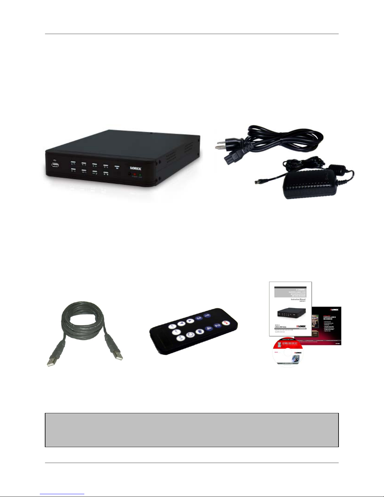
The DVR comes with the following components:
1 x COMPACT DIGITAL VIDEO
RECORDER
1 x USB CABLE
(MALE TO MALE)
1 x REMOTE
CONTROL
1 x POWER ADAPTOR
1 x POWER ADAPTOR CABLE
1 x HARDWARE MANUAL
1 x QUICK START GUIDE
1 x SOFTWARE CD
CHECK YOUR PACKAGE TO CONFIRM THAT YOU HAVE RECEIVED THE COMPLETE
DVR, INCLUDING ALL COMPONENTS SHOWN ABOVE.
8
Page 9

L104 Series - Front
L104 Series - Front
1. USB - One USB 2.0 port is provided to connect the DVR to a PC using the provided USB (Male to
Male) Cable and the included PC Viewer Software. Video can be archived on the PC in either *.MYS
or *.AVI format.
2. UP NAVIGATION / CH1 DISPLAY - Press the key to view Channel 1 during Live View Mode. Use
this key in Menu Mode to Navigate UP and change settings.
3. DOWN NAVIGATION / CH2 DISPLAY - Press the key to view Channel 2 during Live View Mode.
Use this key in Menu Mode to Navigate DOWN and change settings.
4. RIGHT NAVIGATION / CH3 DISPLAY - Press the key to view Channel 3 during Live View Mode.
Use this key in Menu Mode to Navigate RIGHT and change settings.
5. LEFT NAVIGATION / CH4 DISPLAY - Press the key to view Channel 4 during Live View Mode. Use
this key in Menu Mode to Navigate LEFT and change settings.
6. MENU - Press the MENU key to enter or exit the DVR Setup Mode.
7. IR RECEIVER - Receives the signal from the Remote Control
8. PLAY / PAUSE - Press the key to start the playback of Video. Press the key during Video Playback
to Pause.
9. REVERSE / MUTE - Press the key to during video playback to reverse the video (2x, 4x or 8x
speed). Press the key during Live View to MUTE the sound (if using a Sound Input device).
10. FAST FORWARD / SEQUENCE MODE - Press the key to during video playback to Fast Forward
the video (2x, 4x or 8x). Press the key during Live View to Sequence through all Channels.
11. RECORD / PAUSE - Press the key during video playback to freeze the video on the screen. Press
the key during Live Video viewing to start manual recording.
12. POWER LED / HDD ACTIVITY LED - The RED POWER LED indicates that the unit is ON. The
GREEN HDD ACTIVITY LED blinks when video is being recorded to the Hard Drive.
1 2
8
3
9 10 6 11 12
4
5
7
9
Page 10
L104 Series - Back
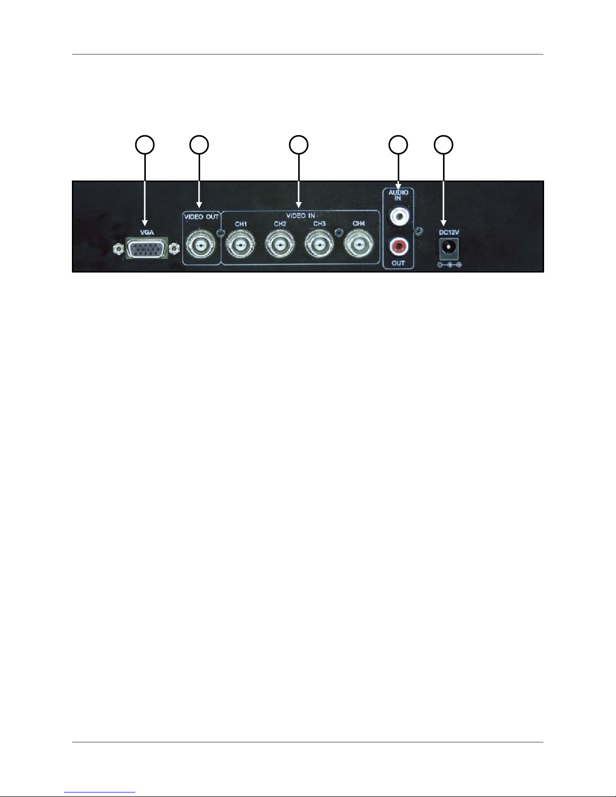
L104 Series - Back
1 2 3 4
1. VGA VIDEO OUTPUT (L104V SERIES ONLY) - Video Output port to connect the unit to a
Computer Monitor. Directly reflects the current onscreen images.
2. BNC VIDEO OUT - Video Output port to connect the unit to a DVR or TV. Directly reflects the
current onscreen images.
3. BNC VIDEO INPUTS - Channel 1~4 camera inputs (used to connect Cameras with BNC connection
type). Cameras with BNC connections require an additional power adapter.
4. RCA AUDIO IN / OUT PORTS – Connection ports for Audio:
• AUDIO IN - Connect One Audio input device such as a microphone to record Audio on
one channel.
• AUDIO OUT - Audio Output port to connect the unit to a secondary DVR or TV.
5. POWER INPUT – Connect to the DVR Power using the power cord provided with the unit. The
power cable connects the DVR to an electrical outlet.
NOTE: The L104 Series Model has a NTSC/PAL selector switch, which changes the video system
between NTSC and PAL modes. This switch is set to NTSC for North America (US/Canada).
5
10
Page 11
p
Remote Control
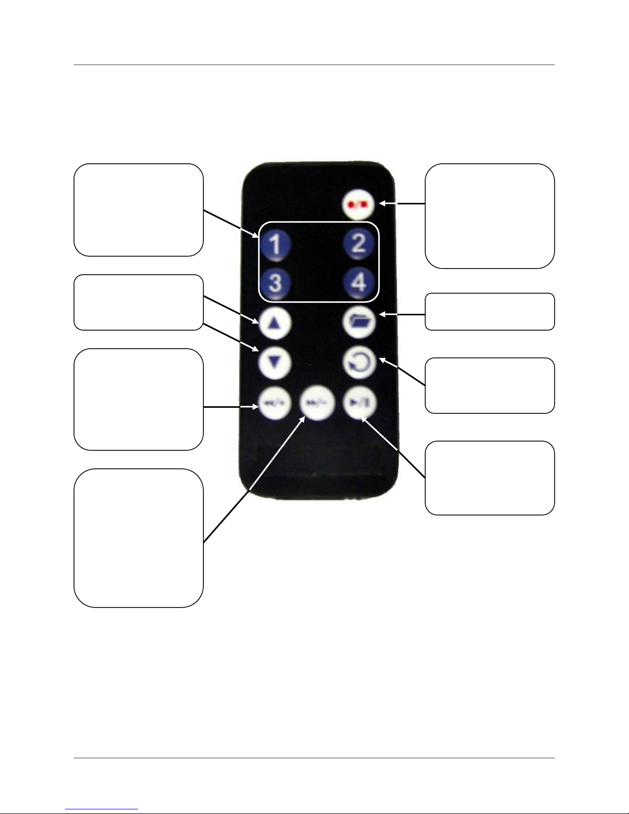
Remote Control
Listed below is a quick reference for the Remote Control. All Buttons described above function the same
as the Front Panel buttons.
CHANNEL BUTTONS
1~4 - Press to select a
specific camera by
number. The Number
Buttons are also used to
input the DVR
Password.
NAVIGATION
- Navigates UP and
DOWN in MENU and
SEARCH modes.
RECORD / STOP
BUTTON - Press the
button to start manual
recording. Pressing the
button again stops
recording or playback of
previously recorded
video.
MENU - Opens the Main
Menu (DVR setup).
REVERSE / MUTE –
- Press to Reverse the
Playback of previously
recorded Video (In
Playback Mode).
- Press to Mute / Unmute
the Volume (if using a
Sound In
FAST FORWARD /
SEQUENCE –
- Press to Fast Forward
the Playback of
previously recorded
Video (In Playback
Mode).
- Press to change the
Live Camera View to
Sequence Mode.
ut device).
ENTER – Accepts
options / enters
submenus in Menu
Mode.
PLAY / PAUSE - Press
the button to start the
playback of Video. Press
the button during Video
Playback to Pause.
11
Page 12
Camera Installation
Camera Installation
Before you install the camera*, carefully plan where and how it will be positioned, and where you will
route the cable that connects the camera to the DVR.
Installation Warnings:
• Select a location for the camera that provides a clear view of the area you want to monitor, which
is free from dust, and is not in line-of-sight to a strong light source or direct sunlight.
• Plan the cables’ route so that it is not close to power or telephone lines, transformers, microwave
ovens or other electrical equipment that could interfere with the DVR.
• Select a location for the camera that has an ambient temperature between 14°F~113°F
(-10°C~45°C)
• If you plan to install the camera in a location that has conditions not recommended in this manual,
consult with a professional installer and consider use of a separate camera cover or housing
• Before starting permanent installation, have another person hold the camera for you while you
verify its performance by observing the image on a monitor.
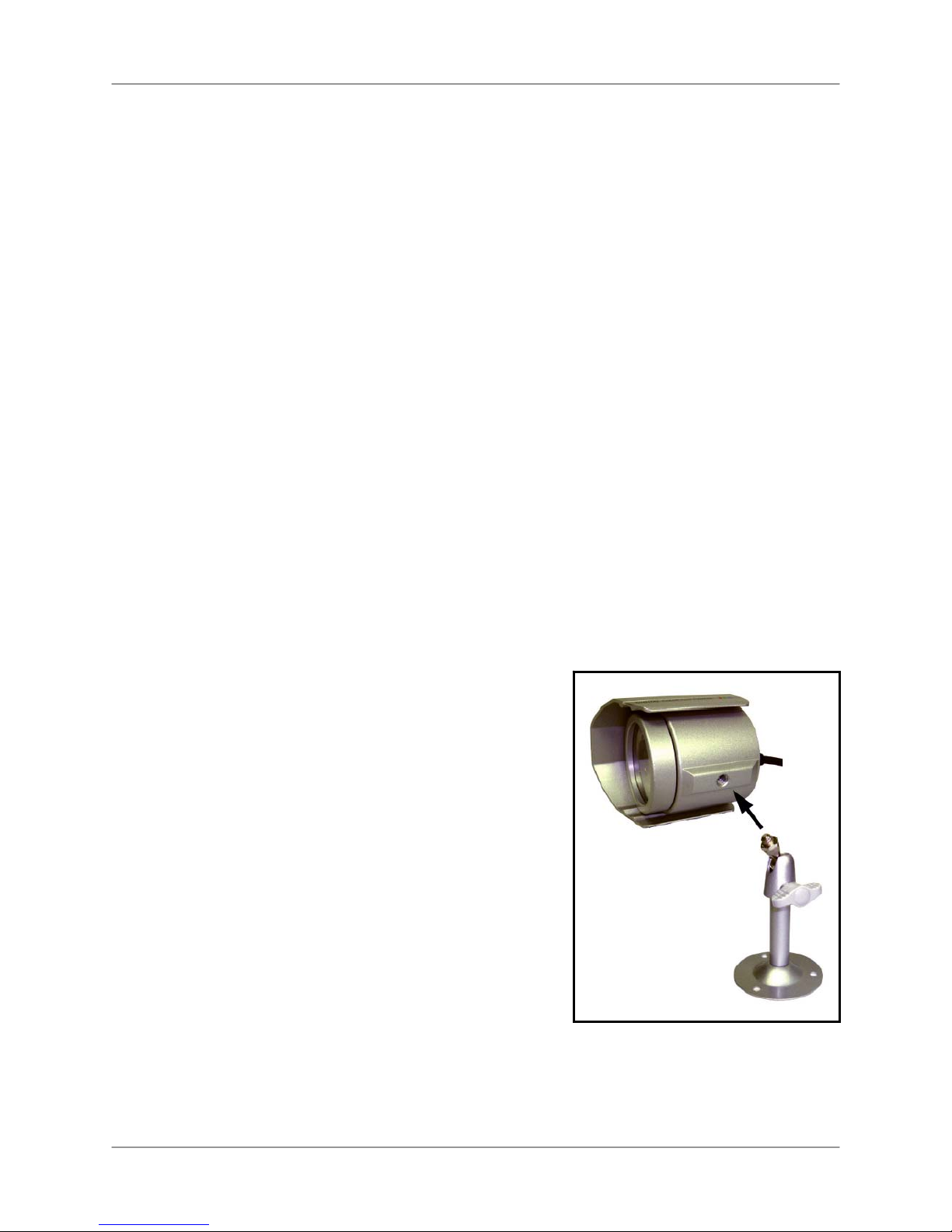
Camera Stand Installation:
1. Attach the pedestal to the ceiling, wall or other surface by the base using the provided screws.
2. The mounting bracket must be attached to a structural device such as a wall stud or ceiling rafter using
the supplied screws.
3. Attach the camera to the pedestal. Adjust the angle of the
camera, and tighten the thumbscrew to set the position
NOTE: The Camera can be attached to the stand
using the screw point on the top or the bottom (to
maintain proper camera alignment). This prevents the
image from becoming inverted.
12
* Camera may not be exactly as shown
Page 13

Connecting BNC Cameras
Connecting BNC Cameras
1. Connect the 60ft Extension cable to the Camera and DVR:
A. Connect the Barrel Power connector to a
power adaptor.
B. Connect the BNC connector to an available
BNC Port (CAM 1~4) on the DVR.
C. Connect the Male Power connector to the
Camera.
D. Connect the BNC connector to the Camera.
2. Connect the Power Adaptor to a wall outlet.
IMPORTANT NOTE: The ends of the extension cable are NOT the same - one end has a Male power
port, and the other has a Female power port. Before permanently running the Camera Extension Cable,
make sure that the cable has been oriented between the Camera and the unit correctly.
Male Power Port - The male power
port end of the Extension cable
connects to the Camera.
Connect to DVR and
Power Adaptor
Female Power Port - The female
power port end of the Extension cable
connects to the Power Adaptor.
Camera Connection Diagram
13
Page 14

Display Modes
Display Modes
Initial Loading Sequence
The unit will automatically begin loading when power is
connected to the DVR.
1. The DVR will perform a Firmware check.
During the loading sequence, the version of
Hardware and Mode (NTSC or PAL) will be
displayed.
2. Once the Firmware check is completed, the
DVR will check the Hard Drive. If a new drive
has been installed, the system will prompt to
format the new drive.
3. The unit will initially load to a split screen view,
displaying all 4 cameras with Camera Names
and the Date and Time. If a camera cannot be
displayed, a V-LOSS message appears instead
of an image.
1
DVR V1-03 EN
2
Checking HDD …
ST3500630AV
Standalone
NTSC
3
2007/10/10 01:02:03
CH1 CH2
CH3 CH4
V-LOSS
NOTE: If a new HARD DRIVE is detected, the
system will prompt you to FORMAT the drive. If you
do not choose to format the HARD DRIVE, the drive
will not be detected by the system.
If you choose to FORMAT a drive in this way, the
drive will no longer be readable by a regular PC
without using the VIEWER software included on the
CD provided with this unit
Press the ◄ & ► Keys to format, or press the
(Menu) button to cancel.
14
Checking HDD …
HDD NEEDS TO FORMAT
ALL DATA WILL BE LOST
(◄►) FORMAT / () CANCEL
Page 15

General Display Overview
1. DATE & TIME - Displays the current
Date and Time for the DVR.
2. PASSWORD INPUT - The
Password Input appears when
manually stopping the Recording, or
entering Menu Mode. The default
password is 111111.
3. CAMERA TITLE & RECORDING
STATUS - Displays the Camera Name
(Up to 8 Characters) and Displays the
current Recording Status (if the System
is recording the
4. V-LOSS MESSAGE - Appears when
the Camera is not sending a Video
Image.
5. REC MESSAGE - Displays the drive
usage when recording.
□ symbol appears).
1
2
3
PASSWORD INPUT (6): ------
□ CH1 CH2 □
□ CH3 CH4 □
4
5
EACH REC [M] (T)
Display Modes
2007/10/10 01:02:03
V-LOSS
Camera Display Modes
Cameras can be displayed in Single Channel, QUAD Channel or Sequence Modes.
• The DVR defaults to Quad view when first loaded.
• Press the Channel Buttons to display a single channel or return to Quad View.
• Press the Sequence button to display all cameras in a rotating sequence mode (3 second view
per channel by default).
SINGLE CHANNEL VIEW – Press the
corresponding Channel Number to view.
□ CH1
QUAD CHANNEL VIEW CAM 1~4 – Press
the VIEW button to display the Quad View.
2007/10/10 01:02:03
CH1 CH2
CH3 CH4
V-LOSS
15
Page 16

System Setup Controls
System Setup Controls
• Enter the MENU screen by pressing the MENU button
(). Enter the password to display the Menu Selection
Screen. The Default password is <111111> - press MENU
to accept the password.
• Scroll through the 7 options by pressing the UP & DOWN
▲▼) buttons on the Front Panel or Remote Control.
(
• To enter a sub-menu, navigate to the option and press the
RIGHT button (
button.
• To change the options, press the RIGHT and LEFT buttons
(
◄►).
• Press the MENU Button () to accept the setting change,
and return to the previous menu.
• To exit the MAIN MENU, press the MENU button ().
►). To exit a SUBMENU, press the MENU
PASSWORD INPUT (6): ------
Menu Navigation Controls
• MENU Button () - Accesses the setup menu, and
returns to previous menu options.
• UP / DOWN Controls (
move through the Menu Options
• LEFT / RIGHT Controls (
to enter a Menu Option, and press left and right to
change the Menu Settings.
▲▼) - Move Up/Down to
◄►) - Move Left / Right
>
SYSTEM SETUP
CAMERA SETUP
RECORD SETUP
RECORD SCHEDULE
MOTION SETUP
HARD DRIVE SETUP
XVGA RESOLUTION 640x480
SYSTEM RESTORE
(▲▼): SELECT (◄►): SET (): EXIT
MAIN MENU
Setup Menu - Options
The Setup Menu has7 options (L104 Series) or 8 options (L104V Series):
• SYSTEM SETUP - The system menu contains basic configuration settings, such as Time/Date,
Password, Alarms and Audio Settings.
• CAMERA SETUP - The camera menu contains the individual camera settings, including viewing,
recording, and image settings.
• RECORD SETUP - This menu contains the recording settings for Single and Quad recording.
• RECORDING SCHEDULE - This menu contains the recording settings by hour
• MOTION SETUP - Configure each camera for Motion Detection Sensitivity.
• HARD DRIVE SETUP – Turns the Overwrite ON/OFF and Formats the Hard Drive.
• XVGA RESOLUTION – Used to change the VGA Resolution output to a PC Monitor (L104V
Series ONLY).
• SYSTEM RESTORE – Restores Factory Defaults
16
Page 17

System Menu Tree
MAIN MENU
SYSTEM SETUP
CAMERA SETUP
RECORD SETUP RECORD QUALITY
BUZZER ALARM TIME
VIDEO LOSS ALARM
AUDIO RECORD
AUDIO MUTE
AUDIO INPUT VOLUME
AUDIO OUTPUT VOLUME
PASSWORD SETUP
TIME SETUP
CAMERA: CH1~CH4
LIVE ON/OFF
RECORD ON/OFF
BRIGHT SETUP
CONTRAST SETUP
COLORS SETUP
AUTO SWITCHING
VIDEO QUALITY
RECORD FRAME RATE
System Setup Controls
17
Page 18

System Menu
(
)
MAIN MENU
RECORD SCHEDULE
MOTION SETUP
HARD DRIVE SETUP
XVGA RESOLUTION
SYSTEM RESTORE
OVERWRITE ENABLED
MASTER HDD SIZE
MASTER HDD USED
MASTER HDD FORMAT
L104V Series ONLY
System Menu
The options in the System Menu control the settings for the DVR.
• BUZZER ALARM TIME: Sets the length of time that the
Alarm Buzzer will sound for (i.e. Video Loss Alarm Buzzer,
Restart of System Alarm Buzzer etc.). The setting for the
Alarm Buzzer ranges from 0 (off) ~ 30 Seconds.
• LOSS ALARM: Turns the Video Loss Alarm to ON or OFF.
• AUDIO RECORD: Turns the Audio Recording to On or OFF
(if using an Audio Device such as a Microphone).
• AUDIO MUTE: Turns the sound from the DVR to ON or OFF.
• AUDIO INPUT VOLUME: Determines the Audio Input
volume (from an Audio device such as a Microphone). The
settings for Audio Input range from 0 (off) ~ 15 (high).
• AUDIO OUTPUT VOLUME: Determines the Audio Output
volume (from the DVR). The settings for Audio Input range
from 0 (off) ~ 15 (high).
• PASSWORD SETUP: Changes the password for the system.
Enter the Current Password (Default: 111111), then enter a
New Password and Password Confirmation. Press the
Menu Button () to exit without changes. See the Front
Panel Buttons for Number Location.
• TIME SETUP: Changes the time and date for the DVR. Set
the Date by Year / Month / Day, and the time by Hour /
Minute / Second.
SYSTEM MENU
BUZZER ALARM TIME
>0
LOSS ALARM
AUDIO RECORD
AUDIO MUTE
AUDIO INPUT VOL.
AUDIO OUTPUT VOL.
PASSWORD SETUP
ON
ON
ON
0
0
TIME SETUP
(▲▼): SELECT (◄►): SET ():EXIT
CURRENT PASSWORD: - - - - - NEW PASSWORD: - - - - - CONFIRM PASSWORD: - - - - - -
TIME SETUP
2007/01/01 01:02:03
^
(▲▼): SELECT (◄►): SET ():EXIT
18
Page 19

System Menu
Camera Setup Menu
The Camera Menu allows the settings to be changed for each of
the 4 cameras.
• CAMERA: Switch between CH1, CH2, CH3 and CH4 to
Record Setup Menu
The Record Menu allows the settings to be changed for ‘Quad’
Recording or ‘Each’ Camera Recording.
NOTE: The Recording Settings for individual cameras cannot be
set (i.e. Settings for Camera 1 cannot be different than settings
for Camera 2). The settings for ‘Each’ Camera refers to the
recording of cameras in full screen mode.
adjust the settings for each camera.
• LIVE ON / OFF: Turns the Live Camera View to ON /
OFF. The camera will continue to record regardless of
the Onscreen Display.
• RECORD ON / OFF: Turns the recording for the Camera
to ON or OFF.
• BRIGHT SETUP: Changes the Brightness of the camera.
The settings for Camera Brightness range from 0 (low) ~
9 (high).
• CONTRAST SETUP: Changes the Contrast of the
camera. The settings for Camera Contrast range from 0
(low) ~ 9 (high).
• COLOR SETUP: Changes the Color of the camera. The
settings for Camera Color range from 0 (low) ~ 9 (high).
• AUTO SWITCHING: Sets the display time for the
Camera when the DVR is in Sequence Mode. The auto
switching time ranges from 0 seconds (OFF) ~ 9
seconds.
• RECORD MODE: Switch between EACH and QUAD to
adjust the recording settings for Camera View and QUAD
View*.
• VIDEO QUALITY: Change the Video Quality for the
recording to Low, Normal or High.
• RECORD FRAME RATE: The Recording Frame rate is
shared across all cameras (i.e. 30 FPS = 7.5 FPS per
camera). Change the Recording Frame Rate (in seconds)
to 1, 2, 3, 4, 5, 7, 10, 15 or 30.
NOTE: If Audio Recording is ON, the available frame
rates are 4, 5, 7, 10, 15 or 30.
* NOTE: If the Recording Mode is set to QUAD during playback, the DVR will record in QUAD Mode
and not in Single Channel Mode.
(▲▼): SELECT (◄►): SET ():EXIT
(▲▼): SELECT (◄►): SET ():EXIT
CAMERA SETUP
>CH1
CAMERA
LIVE ON / OFF
RECORD ON / OFF
BRIGHT SETUP
CONTRAST SETUP
COLOR SETUP
AUTO SWITCHING
RECORD SEUP
RECORD MODE
VIDEO QUALITY
RECORD FRAME RATE
ON
ON
0
0
0
0
EACH
LOW
1
19
Page 20

System Menu
Record Schedule Menu
The Record Schedule controls the Recording
Type per hour for 24 hours (full day) for both
Individual Camera and QUAD recording types.
The Available Recording Types include:
• T : Continuous (Schedule*) Recording
* NOTE: To configure the DVR for Scheduled Recording, set the Record Schedule to the Continuous
Recording Type for the desired times (i.e. to set the DVR to begin recording from 3pm ~ 10pm, set the
Record Schedule to T for all time blocks between 15hr~20hr as shown above).
Motion Setup Menu
The Motion Setup controls the Motion
Detection sensitivity for each camera. The
sensitivity ranges from 0 (off) ~ 9 (high
sensitivity detection).
NOTE: To enable Motion Detection Recording,
Set the Record Schedule Type to ‘M’ for the
desired time block(s).
Hard Drive Setup Menu
The hard drive setup controls the installed hard
drive (if included).
(The DVR is constantly recording on all
channels, based on individual camera
settings).
• M : Motion Recording (The DVR only
records when Motion is detected).
• - : Recording is OFF
• OVERWRITE ENABLED: Sets the
Hard Drive Overwrite to YES or NO. If
set to YES, the drive will overwrite
older video once full.
• MASTER HDD SIZE: Displays the size
of the installed Hard Drive (in MB). This
is a display only, and cannot be
changed in the menu.
• MASTER HDD USED: Displays the
amount of the Drive space used (in
MB). The percentage is also displayed
(%). This is a display only, and cannot
be changed in the menu.
+ ----------- - - - - -TTTTTTTT- - +
| | | | | | | |
0 3 6 9 12 15 18 21
CHANNEL 1 SENSITIVITY
CHANNEL 2 SENSITIVITY
CHANNEL 3 SENSITIVITY
CHANNEL 4 SENSITIVITY
OVERWRITE ENABLED
MASTER HDD SIZE
MASTER HDD USED
MASTER HDD FORMAT
RECORD SCHEDULE
(▲▼): SELECT (◄►): SET ():EXIT
MOTION SETUP
(▲▼): SELECT (◄►): SET ():EXIT
HARD DRIVE SETUP
###### MB
# MB #%
(▲▼): SELECT (◄►): SET ():EXIT
0
5
6
9
NO
20
Page 21

System Menu
Hard Drive Setup Menu (cont.)
• MASTER HDD FORMAT: Formats the DVR
NOTE: Formatting the Hard Drive removes all accessibility to the Video Data on the Hard Drive (when
using the DVR Search functions); however the data is still available through the PC Viewer (until
overwritten).
System Restore
The System Restore option will reset the DVR to the
Factory Default settings.
NOTE: The System Restore does not format the hard
drive.
Press the Left and Right Buttons (
format the drive, or press the Menu Button -() to
return to the previous menu without a System Restore.
Hard Drive. Enter the System Password to
format, or press the Menu Button () to
cancel the format.
XVGA Resolution (L104V Series)
The XVGA Resolution controls the display output from
the DVR VGA Port (L104V Series Only) to the Viewing
PC Monitor. Use the Left and Right (
change the setting to 640 x 480, 800 x 600, 1024 x 768
or 1280 x 1024.
◄►) buttons to
◄►) together to
ENTER PASSWORD: - - - - - -
MAIN MENU
SYSTEM SETUP
CAMERA SETUP
RECORD SETUP
RECORD SCHEDULE
MOTION SETUP
HARD DRIVE SETUP
>
XVGA RESOLUTION 640x480
SYSTEM RESTORE
(▲▼): SELECT (◄►): SET ():EXIT
SYSTEM RESTORE?
(◄►): YES ():NO
21
Page 22

Playback Controls
Playback Controls
• Press the PLAY/PAUSE (
Playback Mode, playing the most recent event.
• To search for a previous event, press the MENU Button () when in Playback Mode.
Pressing the MENU button will open the PLAYBACK EVENT SEARCH MODE window.
1. DATE & TIME: Displays the Start and
End Date/Time range. Use the Arrow
Buttons (
dates.
2. EVENT LIST: Displays a listing of
Events. The Event List displays the
Event Type (Time, Motion or Manual),
and the Date and Time the event
occurred.
NAVIGATION MENU: Displays a list of
3.
navigation buttons:
•
•
•
•
•
◄▲▼►) to change the
(▲▼) - Select an Event, or
change the Date and Time.
(◄►) - Navigation keys
(►/||) - Press to begin the
playback of the selected event.
() - Press to Exit from the
Search screen.
(●/■) - Switch between the
Date/Time and Event List.
►/ ||) button when in Live View Mode will put the DVR into
>
SEARCH TIME
1
07 / 01 / 01 01:02:03 - 07 / 01 / 27 12:15:55
2
01
02
03
04
05
3
(▲▼): SELECT (◄►): SET (►/||): PLAY
HARD DRIVE : MASTER
TIME
TIME
MOTION
MOTION
TIME
():EXIT (
2007 / 01 / 05 02:15:55
2007 / 01 / 08 13:55:24
2007 / 01 / 11 18:16:22
2007 / 01 / 18 03:47:29
2007 / 01 / 26 09:36:27
●): SELECT EVENT / TIME
Playback
During the Video Playback, the following buttons are used to control the Video:
• (►/||) - Press to Play / Pause the Video.
•
(►►) - Press to Speed Up the forward
playback of the Video (2x, 4x or 8x speed).
(◄◄) - Press to Speed Up the reverse
•
playback of the Video (2x, 4x or 8x speed).
(● / ■) – Press to Stop the Video, and exit
•
from Video Playback mode.
22
2007/10/10 01:02:03
CH1 CH2
CH3 CH4
V-LOSS
► [M]
Page 23

DVR PC Viewer Software
DVR PC Viewer Software
The PC Viewer software (included with the DVR) allows the Video Data from the DVR to be viewed using
a USB link to a PC. Video saved to the PC Hard Drive (from the DVR) is written as a *.MYS file format,
and can only be read using the PC Viewer Software.
System Requirements:
Supported Operating System
PC Hardware & Software
NOTE: The PC Viewer Software is not compatible with Windows Vista. Please visit us on the web for the
most current Manuals, Quick Start Guides and Firmware at: http://www.lorexcctv.com/support
Starting the PCViewer Application:
To run the PC Viewer Application, run the
PCViewer_V3.8_EN.exe file from the included CD-ROM. The
application will attempt to detect a connection to the DVR before
launching the viewing window:
• If the DVR is detected, the application will load and prompt the user
to begin playing the most recent recorded video (Recent Position
dialogue window).
• If the DVR is not detected, the application will open an error
dialogue window (Detection Error dialogue window) indicating
the storage device is not found, and will launch the MYS
Player Window.
Windows 2000 (SP4) or Windows XP (SP2 or higher)
Pentium 1.0 GHz; 512 MB RAM; DirectX 7.0
Connecting the DVR:
1. Make sure that the power cable for the DVR is disconnected.
2. Use the provided USB Cable (Male to Male). Connect one end to
the front USB Port on the DVR, and connect the other end to a PC.
USB Port.
3. Connect the power cable to the DVR. The PC should
automatically detect the DVR as a New USB Device and
install the Hardware.
4. Launch the PC Viewer Application. The software will
automatically detect the DVR, and launch the “PC
Viewer Storage Device Detection” window.
23
Page 24

PC Viewer – Main Window
PC Viewer – Main Window
1
2
3
4
5 6 7 8 9 10 11 12
13
1. PC VIEWER MENU CONTROLS – The Menu Controls function in the same way as the GUI
Controls on the Viewer Window:
• Function Selector: Controls the onscreen location of the program and closes the
application.
• PC Viewer: Playback controls (Play, Pause, Fast Forward & Reverse).
• Channel: Controls the onscreen video display (Single Channels, 2-Channel View & Quad
View).
• Capture: Saves the current video as MYS or AVI video, or JPEG still image.
• Audio Control: Raises, Lowers or Mutes the Volume.
• MYS Player: Loads an MYS File into the player.
• Searcher: Searches the DVR by event or time.
• Setting: Changes the default video save directory.
• Help: Displays the application Version information.
2. VIDEO DISPLAY – Displays the Video in Single, 2-Channel or Quad View. The video is displayed
in Quad view when the application loads.
24
Page 25

PC Viewer – Main Window (cont …)
PC Viewer – Main Window (cont …)
3. CHANNEL TITLE & DATE – Displays the Channel Description (CH1 ~ CH4), and the Date and Time
of the Recorded Video.
4. MYS PLAYER BUTTON - Launches the MYS Player Window (see below).
5. STREAM SELECT BUTTON
6. DVR STORAGE DEVICE INFORMATION –
Displays details about the DVR including the
Connection Type, Device Type, Storage Size and Length
of Video (Stream in MB).
7. CHANNEL SELECTION BUTTONS – Changes the Onscreen View to
Quad, 2-Channel, or switches between CH1 ~ CH4
8. VIEWER CONTROLS – Controls the playback of the current onscreen
Video (Reverse Playback, Step-Reverse Single Frame, Pause/Play, StepForward Single Frame and Fast Forward).
9. CAPTURE VIDEO IN MYS FORMAT –
default directory. To save an MYS file:
• Load the Video into the Player Window.
• Use the Viewer Controls to locate the point in the video to start the Video
– Used to select another Stream Device (disabled).
Saves the current video stream as an MYS file to the
Save.
• Press the PAUSE button on the Viewer Controls
• Press the Capture MYS Stream button. A Capture Status Window
with a red bar will appear. Press the ‘Stop Capturing’ button to end
the capture.
• A dialogue window will appear indicating that an MYS file was
created.
25
Page 26

PC Viewer – Main Window (cont …)
10. CAPTURE VIDEO IN AVI FORMAT
– Saves the current video stream as an AVI file (AVI
Files can be played back in a Video Playback application such as Windows Media Player®, as long as
the correct Codecs are installed on the PC).
• Load the Video into the Player Window.
• Use the Viewer Controls to locate the point in the
video to start the Video Save.
• Press the PAUSE button on the Viewer Controls
• Press the Capture AVI Stream button. A ‘Save File’
dialogue window will appear prompting the user to
select a save directory.
• Once a Save Directory is selected, a Video
Compression window will appear. Select the desired
Compression Type (Codec)*:
o Cinepak Codec by Radius
o Intel 4:2:0 Video V2.50
o Intel Indeo(R) Video R3.2
o Intel IYUV Codec
o Microsoft RLE
o Microsoft Video 1
o Microsoft H.263 Video Codec
o Microsoft H.261 Video Codec
o Intel Indeo® Video 4.5
o Indeo® Video 5.10
o DivX® 6.1.1 Codec (1 Logical)
o DivX® 6.1.1 YV12 Decoder
o Sunplus 32-bit Compressor
o VCM IMM4 Decoder
o Xvid MPEG-4 Codec
o Full Frames (uncompressed)
* NOTE: Video Codecs for playback are NOT supplied with this Software. Codecs can be downloaded
from the Internet on sites such as http://www.microsoft.com
or http://www.Divx.com
• Once the compression type is
selected, press the OK button to
save the video.
• Press the AVI Capture Button to
end the Video Capture.
11. CAPTURE JPEG STILL IMAGE – Saves the current video image as a JPEG Image file.
• Load the Video into the Player Window.
• Use the Viewer Controls to locate the point in the video to start the Image Save.
• Press the PAUSE button on the Viewer Controls
• Press the Capture JPEG Image
button.
• A ‘Screen Capture Message’
window will appear indicating a
successful image capture.
12. AUDIO CONTROLS – Controls the Audio Playback Volume and Mute Status.
NOTE: If no audio capture device has been connected to the DVR, audio will not be
recorded to the DVR.
13. PLAYBACK STATUS – Indicates the current Video Playback status as
PLAYING or PAUSE.
26
Page 27

Using the MYS Player
When the MYS Player opens, an ‘Open File’ dialogue
box appears. Select the MYS File to play back in the
Viewer, and press the Open button.
MYS Player – Main Window
1
2
3
4
5
6
Using the MYS Player
7
8 9 10
27
Page 28

MYS Player – Main Window (cont …)
MYS Player – Main Window (cont …)
1. MYS PLAYER MENU CONTROLS – The Menu Controls operate in the same way as the PC Viewer
Controls (see above).
2. VIDEO DISPLAY – Displays the Video in Single, 2-Channel or Quad View. The video is displayed in
Quad view when the application loads.
3. CHANNEL TITLE & DATE – Displays the Channel Description (CH1 ~ CH4), and the Date and Time
of the Recorded Video.
4. MYS PLAYER BUTTON
5. OPEN VIDEO BUTTON
6. FILE DETAILS – Displays the MYS Video File Name and File
Size (in MB).
7. MYS PLAYBACK CONTROLS – Controls the playback of the current
onscreen Video (Reverse Playback, Step-Reverse Single Frame,
Pause/Play, Step-Forward Single Frame and Fast Forward).
8. CAPTURE JPEG STILL IMAGE – Saves the current video image as a JPEG Image file.
• Load the Video into the Player Window.
• Use the Viewer Controls to locate the point in the video to start the Image Save.
• Press the PAUSE button on the Viewer Controls
• Press the Capture JPEG Image
button.
• A ‘Screen Capture Message’
window will appear indicating a
successful image capture.
9. AUDIO CONTROLS – Controls the Audio Playback Volume and Mute Status.
NOTE: If no audio capture device has been connected to the DVR, audio will not be
recorded to the DVR.
10. PLAYBACK STATUS – Indicates the current Video Playback status as
PLAYING or PAUSE.
– Returns to the PC Viewer Application Window (see above).
– Used to select a different MYS Video File.
28
Page 29

DVR Specifications - Appendix #1
DVR Specifications - Appendix #1
DVR
Display Frame Rate NTSC: 120 FPS (4 x 30 FPS)
PAL: 100 FPS (4 x 25 FPS)
Recording Frame Rate
(QUAD Mode)
Recording Frame Rate
(Single Mode)
Recording Modes Motion / Continuous / Scheduled
Resolution Display NTSC: 720 x 480
Resolution Recording NTSC: 640 x 224
MJPEG Compression Format Low: 12 kb / frame
Audio Function Audio Input / Output: Real Time Recording and
HDD Capacity Maximum 1 x 500 GB HDD
Backup Device VCR / USB PC Link (USB Cable connection to
Search Mode Time / Date / Event
System Recovery Power Recovery, auto restore, record mode
Features & Functions Motion Detection, Loss Detection, Buzzer Alarm,
Video Input 4 Channel composite (BNC) NTSC / PAL
Video Output 1 Channel composite VGA
VGA Output (L104V Series) 640 x 480, 800 x 600, 1024 x 768, 1280 x 1024
Audio Input 1 x RCA Audio Input
Audio Output 1 x RCA Audio Output
Power (AC input) DC 12V / 4A
Dimensions (W x H x D) 8.6” x 1.8” x 11.3”
Weight 3.4 lbs / 1.5 kg
Dimensions with Package
(W x D x H)
Weight with Package 10 lbs / 4.5kg
Operating Environment
Approval FCC, CSA, UL
NTSC: Max 30 FPS
PAL: Max 25 FPS
NTSC: Max 7.5 FPS (30 FPS / 4)
PAL: Max 6.25 FPS (25 FPS / 4)
PAL: 720 x 576
PAL: 640 x 272
Normal: 15 kb / frame
High: 20 kb / frame
Playback
Computer with PC Application)
Brightness Adjustment, Contrast Adjustment, USB
Output to PC (PC Link Function)
INPUTS/OUTPUTS
1 Channel VGA (Only available on L104V Series)
Resolution
GENERAL
AC 110V~240V 50/60hz
220mm x 48mm x 288mm
15.3” x 13.0” x 5.5”
388mm x 338mm x 89mm
Temperature: 0 ∼ 40 ℃, Humidity: 0 ∼ 80 %
29
Page 30

Full Connectivity Diagram – Appendix #2
Full Connectivity Diagram – Appendix #2
The following diagram outlines a general set of connections available with the DVR.
DVR
BNC CAMERAS MICROPHONE
PC MONITOR
(L104V SERIES
VGA ONLY)
30
SLAVE MONITOR,
TV OR
OBSERVATION
SYSTEM
Page 31

Hard Drive Replacement - Appendix #3
Hard Drive Replacement - Appendix #3
The DVR comes with a pre-installed Hard Drive; however the unit will work with a replacement single IDE
Hard Drive (up to 500GB).
NOTE: Make sure that the DVR is OFF and the power cable has been disconnected before changing the
Hard Drive.
Removing the Back Cover and Installed Drive
1. Remove the seven (7) screws from the DVR
Cover. Remove the cover panel.
2. Remove all cables from the previously installed
drive.
3. Remove the screws holding the drive to the
case.
Setting the New Drive to Master
• Refer to the General Jumper Pin Setting on HDD Surface (generally located on a sticker on the
top of the drive).
• Set the Jumper Pin Set to Master (1 Drive).
NOTE: Use an IDE Hard Drive.
31
Page 32

Hard Drive Replacement (cont …)
Hard Drive Replacement (cont …)
Installing the New Drive
• Place the new drive in the case, and reattach the holding screws.
• Reconnect the cables in the same way as connected to the previous drive.
o Reconnect the IDE Cable. Confirm that the cable is securely connected within the DVR
and to the Hard Drive.
o Reconnect the Hard Drive power cable. Confirm the cable is securely connected to the
Hard Drive.
• Replace the drive cover on the top of the DVR, and reattach with the seven (7) screws.
New Hard Drive Format
The New Hard Drive MUST be formatted.
NOTE: If a new HARD DRIVE is detected, the
system will prompt you to FORMAT the drive. If you
do not choose to format the HARD DRIVE, the drive
will not be detected by the system.
If you choose to FORMAT a drive in this way, the
drive will no longer be readable by a regular PC
without using the VIEWER software included on the
CD provided with this unit
Press the ◄ & ► Keys to format, or press the
(Menu) button to Cancel.
(◄►) FORMAT / () CANCEL
Checking HDD …
HDD NEEDS TO FORMAT
ALL DATA WILL BE LOST
32
Page 33

Troubleshooting – Appendix #4
Troubleshooting – Appendix #4
When a malfunction occurs, it may not be serious and can be corrected easily. The following describes
the most common problems and solutions. Please refer to the following before calling Lorex Technical
Support:
Problem:
DVR Unit is not receiving power, or is not powering up
Check:
• Confirm that all cables are connected correctly.
• Confirm that the power adapter is securely connected to the back of the unit.
• Confirm that there is power at the outlet by:
o Connecting the power cable to another outlet
o Testing the outlet with another plugged device (such as an electric calculator or phone
charger)
• If the unit is connected through a power bar or surge protector, try bypassing the bar and
connecting the power directly to the wall outlet.
• Confirm that the unit is powered on (LED indicators on the front should be ON).
Problem:
The DVR is not responding when any of the buttons are pushed.
Check:
• Turn the master power OFF by removing the POWER CABLE. The LED indicators should be
OFF.
• Wait for 1 minute – Reconnect the POWER CABLE.
• The unit will make an audible alert when powered back on
Problem:
The image on the DVR is too dark or too bright
Check:
• Adjust the CONTRAST and BRIGHTNESS of the unit (Refer to the Menu section)
Problem:
The image on the DVR does appear, but does not have sound.
Check:
• Check the VOLUME
• Check the CAMERA connection to the DVR (DIN CONNECTION ONLY).
• Confirm that the Camera has sound capabilities (Refer to the manual for the camera model for
further information on the Camera functionality)
33
Page 34

Troubleshooting (cont…)
Troubleshooting (cont…)
Problem:
The picture on the DVR is poor, shrinks or flickers
Check:
• Check the camera video cable and connections
• Disconnect and reconnect the cable at the DVR and at the Camera
• Clean the camera lens
• Adjust the CONTRAST and BRIGHTNESS settings in the Menu
• Check that the Camera is not in direct sunlight
Problem:
There is no picture appearing on a Channel / Camera is not displaying
Check:
• Check the camera video cable and connections
• Disconnect and reconnect the cable at the DVR and at the Camera
• Try moving the camera to another channel or use another cable
34
Page 35

Recording Charts (NTSC / PAL) - Appendix #5
Recording Charts (NTSC / PAL) - Appendix #5
The following charts are based on an 80GB Hard Drive (using 4 Cameras) and provide an approximation
of hours based on the Quality and Frame Rate. The charts are provided for reference only, as actual
recorded data may vary in size.
Recording Results in NTSC Format
Video
Signal
NTSC
Recording Results in PAL Format
Video
Signal
PAL
Display
Format
QUAD
Mode
EACH Mode
(Full
Screen)
Display
Format
QUAD
Mode
EACH Mode
(Full
Screen)
Video
Quality
High
Normal
Basic
High
Normal
Basic
Video
Quality
High
Normal
Basic
High
Normal
Basic
30 FPS 15 FPS 7 FPS 1 FPS
36 Hours
48 Hours
58 Hours
64 Hours
90 Hours
112 Hours 224 Hours 448 Hours 3,360 Hours
25 FPS 12 FPS 6 FPS 1 FPS
38 Hours
48 Hours
60 Hours
62 Hours
90 Hours
118 Hours 236 Hours 472 Hours 2,950 Hours
72 Hours
96 Hours
116 Hours 232 Hours 1,740 Hours
128 Hours 256 Hours 1,920 Hours
180 Hours 360 Hours 2,700 Hours
76 Hours
96 Hours
120 Hours 240 Hours 1,500 Hours
124 Hours 248 Hours 1,550 Hours
180 Hours 360 Hours 2,250 Hours
144 Hours 1,080 Hours
192 Hours 1,440 Hours
152 Hours 950 Hours
192 Hours 1,200 Hours
35
Page 36

Optional Accessories
Optional Accessories
The following accessories are available to add to your existing DVR
BNC
CAMERAS
BNC DOME TYPE
CAMERAS
CAMERA
EXTENSION
CABLES
NIGHT VISION
ACCESSORIES
CAMERA
ADAPTOR
CABLES
To order these accessory items, or for a complete listing of
available products, please visit us on the web at:
36
WWW.LOREXCCTV.COM
Page 37

It’s all on the web
Product Information
User Manuals
Quick Start Guides
Specification Sheets
Software Upgrades
Firmware Upgrades
VISIT
www.lorexcctv.com
Lorex Technology Inc.
www.lorexcctv.com
 Loading...