

Page 1

LOREX MODULE REMOTE
ACCESS SETUP GUIDE
DLINK DI–624
Instruction Manual
English Version1.0
Copyright © 2005 Strategic Vista International Inc
www.lorexcctv.com
Page 2

Table of Contents
Before You Start .....................................................................................................................................3
1 Configure your router to enable access from the Internet...............................................................4
Step 1: Log into your Router's Administration Server.........................................................................4
Step 2: Set up the Static IP address...................................................................................................5
Step 3: Create Data Path from Internet to Lorex Module....................................................................7
2 Register for Dynamic Domain Name Service (DDNS)....................................................................9
3 Configure the Lorex Module for DDNS and Password Access.....................................................11
Step 1: Set up the DDNS client.........................................................................................................12
Step 2: Set up a Password to Secure your Module ..........................................................................12
4 Configure the Lorex Player ...........................................................................................................14
Step 1: Update the Lorex Player for the new password....................................................................14
Step 2: Set up Remote access from the Internet..............................................................................15
List of Figures
Figure 1: DLink-624 Wireless Broadband Router.................................................................................... 3
Figure 2: Password Prompt....................................................................................................................... 4
Figure 3: WAN Status............................................................................................................................... 5
Figure 4: Set Static IP Address................................................................................................................. 6
Figure 5: Virtual Server............................................................................................................................ 7
Figure 6: DDNS Registration.................................................................................................................... 9
Figure 7: Camera Screen Settings........................................................................................................... 11
Figure 8: Network Screen....................................................................................................................... 12
Figure 9: Account Settings Screen.......................................................................................................... 13
Figure 10: Choose Edit Camera Server .................................................................................................. 14
Figure 11: Camera Server Settings......................................................................................................... 14
Figure 12: Add Camera Location ........................................................................................................... 15
Figure 13: Camera Location and Camera Server Settings...................................................................... 15
Figure 14: Camera Sever Settings........................................................................................................... 16
Figure 15: User Name and Password...................................................................................................... 16
Figure 16: Define the Camera................................................................................................................. 16
Figure 17: Camera Icon .......................................................................................................................... 17
Page 3
(
)
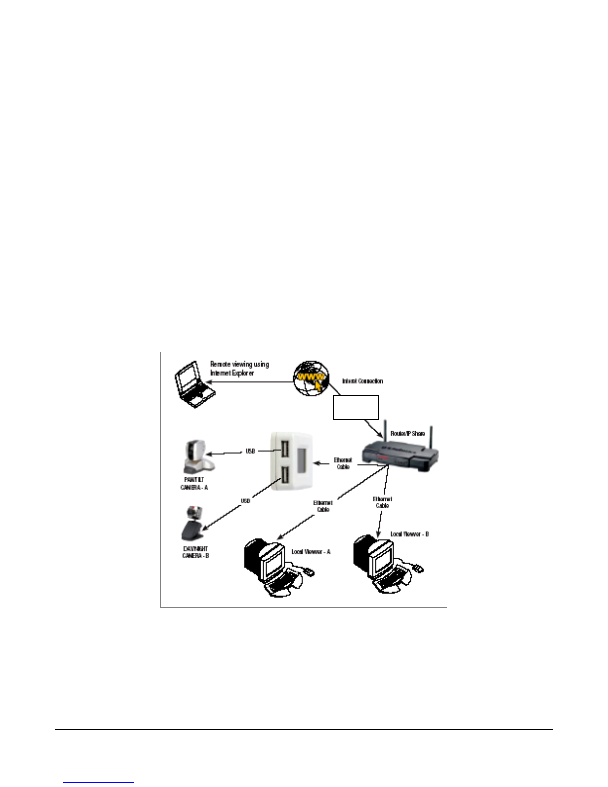
Before You Start
This section will help you in setting up and configuring your Camera(s) and PC(s) to be
able to view the video images from remote locations on the Internet.
NOTE We assume that you already have the camera modules hooked up and working and
that you can view video from within your Local Area Network (LAN).
If not, please consult the Quick Start guide or the Lorex Manual before you continue
with remote access setup.
This document will help you do the following:
• Configure your router to enable access from outside the LAN
• Register for the Dynamic Domain Name Service (DDNS) from Strategic Vista
• Configure the Lorex Module to operate with DDNS
• Set up a password to secure your camera module
• Configure the Lorex Player to reach the camera module using the DDNS.
Modem
external
Figure 1: DLink-624 Wireless Broadband Router
© 2005 Strategic Vista International Inc. - 3 IPSC2230_2260_MANUAL-EN.R1.doc
Page 4

1 Configure your router to enable access from the Internet
To view video images remotely across the Internet involves setting up your broadband
router, see Figure 1.
The example shown here uses the DLink-624 Wireless broadband Router.
Step 1: Log into your Router's Administration Server
Use a web browser on a computer that is connected to the LAN side of the router to
access your broadband router.
Typically this will be at an IP Address such as 192.168.1.1 or maybe 192.168.0.1.
Consult your router manual for exact details.
(1) Enter the username and password for your particular router – by default the
DLink-624 uses 'admin' as the username and the password is blank.
Figure 2: Password Prompt
© 2005 Strategic Vista International Inc. - 4 IPSC2230_2260_MANUAL-EN.R1.doc
Page 5
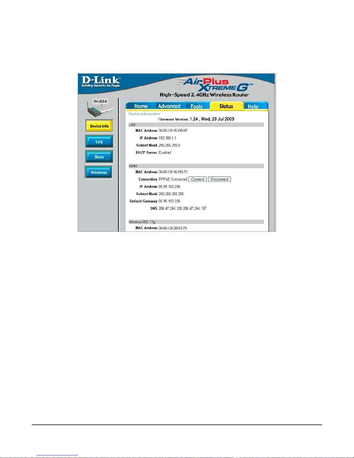
(2) Select a screen display that provides device and/or network status. In the
case of the DLink-624 it will appear as follows:
Figure 3: WAN Status
The status and external IP Address of the router are clearly shown in the WAN section.
Step 2: Set up the Static IP address
Some routers, including the DLink-624, have the capability to fix the internal IP
addresses that are distributed using DHCP.
If your router supports this feature, you will want to set it up to ensure that the internal IP
address never changes.
In the case of the Dlink-624, click the 'DHCP' button and then click on the DHCP Server
'Enabled' radio button. From the DHCP client dropdown list select the entry that
corresponds to the Lorex Module and click on the 'clone' button. Click on the Static
DHCP 'Enabled' radio button. Then click on the 'Apply' button to save this configuration.
© 2005 Strategic Vista International Inc. - 5 IPSC2230_2260_MANUAL-EN.R1.doc
Page 6
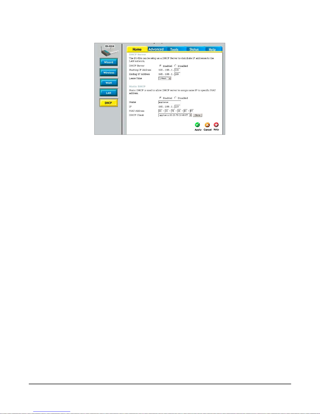
Figure 4: Set Static IP Address
If your router does not support the Static DHCP feature, then you will want to set the IP
Address explicitly.
Choose a new address value that is not already assigned and is outside of the range of
the DHCP server to avoid address conflict. (i.e. does not fall within the Starting and
Ending IP Address).
Use the new address in the following setup. If you do re-assign the IP address,
remember to also set it in the Lorex Module using the Lorex Utility (see the manual on
how to do this).
© 2005 Strategic Vista International Inc. - 6 IPSC2230_2260_MANUAL-EN.R1.doc
Page 7

Step 3: Create Data Path from Internet to Lorex Module
Most routers have a way of setting up forwarding rules to allow external Internet client
applications to access devices on the LAN.
In the case of the DLink-624 router select the 'Advanced' tab and you will see the
following screen:
Create a path for your streaming video by entering values as shown:
• Click the 'Enabled' radio button
• Enter the Name (this is your choice)
• Enter the Private IP. This must be the same IP address that appears in the LCD of
the Lorex Module and/or the static IP set in the previous step.
• Set the Protocol Type to 'UDP',
• Set the Private Port to '9001'
• Set the Public Port to '9001'
• Set the Schedule to 'Always'
• and select the 'Apply' button.
© 2005 Strategic Vista International Inc. - 7 IPSC2230_2260_MANUAL-EN.R1.doc
Figure 5: Virtual Server
Page 8

This will create a data path that the Lorex Player will use to access the video stream and
will allow you to view the video images. If you also want to access the Lorex Module
using a web browser, then do the following as well:
NOTE Web servers are favourite targets of hackers, and so doing this last step may make
your Lorex Module a little less secure.
• Click the 'Enabled' radio button
• Set the Name (this is your choice, as long as it is unique)
• Set the Private IP (this must be the same IP address as the previous)
• Set the Protocol Type to 'TCP',
• Set the Private Port to '80'
• Set the Public Port to '80'
• and select the 'Apply' button.
© 2005 Strategic Vista International Inc. - 8 IPSC2230_2260_MANUAL-EN.R1.doc
Page 9

2 Register for Dynamic Domain Name Service (DDNS)
Why should I register for DDNS Service?
Unless you specifically obtain a static external IP address, your broadband Internet
address, which is assigned by your service provider, is subject to change on a regular
basis.
Dynamic DNS is the service whereby the camera module registers the IP address of the
router with the external DNS system.
NOTE In order to be able to locate your home network, you must sign up to use a Dynamic
DNS system.
NOTE You need only have one device registering the IP Address of the network.
If you already have DDNS support by a different means, you may not need to do this
step.
Using a web browser go to dns1.strategicvista.net, and click on the 'create account'
link.
© 2005 Strategic Vista International Inc. - 9 IPSC2230_2260_MANUAL-EN.R1.doc
Figure 6: DDNS Registration
Page 10

You will be asked to provide the following information:
• Your e-mail address
• A secret password
• Your name
• Your Region ( state or province)
• Your country
• Your product license number – This is the same number you entered when
installing your Lorex Player. The license number is made up of:
• 6 to 8-character product code that can be found on the packaging,
• 12-character MAC number
NOTE The MAC address is found on the back label of the IPSC2230 video server
MAC (Media Access Control Address) the hardware address that is unique to this
product
After you select 'Create New Account' you will receive a username and password
confimation by e-mail, which you will use in the following steps.
If you wish to change any of the parameters you may revisit the Registration page.
However, you will be prompted for the existing secret password before you will be
allowed access.
© 2005 Strategic Vista International Inc. - 10 IPSC2230_2260_MANUAL-EN.R1.doc
Page 11

3 Configure the Lorex Module for DDNS and Password Access
In order to use this service you must have signed up with the StrategicVista network in
Register for Dynamic Domain Name Service (DDNS), page 9.
You will have received an e-mail providing you with the parameters to enter in this part
of the setup.
The Lorex Module can be configured using the Lorex Utility application or using a web
browser. The following description is for the web browser:
(1) Bring up a web browser on a PC that is connected to the same LAN as the
Lorex Module.
(2) Enter the module's IP address in the browser address bar.
The Camera Settings screen will appear, see Figure 7:
Figure 7: Camera Screen Settings
© 2005 Strategic Vista International Inc. - 11 IPSC2230_2260_MANUAL-EN.R1.doc
Page 12

Step 1: Set up the DDNS client
(1) Click on the 'Network' option, in the left-hand panel under 'Basic Settings'.
The following screen will appear:
Figure 8: Network Screen
(2) Enter the Dynamic DNS settings, as described in the confirmation e-mail.
(3) Change the 'Use Public IP to Register' setting to 'Yes'.
(4) Click on the 'Apply' button at the bottom of the page.
(5) Click on the 'Update' button after the screen refreshes.
Step 2: Set up a Password to Secure your Module
The connection that you currently have is suitable for use on a private Local Area
Network.
If you are concerned that others can get access to your Lorex Module, you must enable
password protection as follows:
(1) Click on the 'Account Settings' option In the left-hand panel, under 'Basic
Settings'.
© 2005 Strategic Vista International Inc. - 12 IPSC2230_2260_MANUAL-EN.R1.doc
Page 13

The following screen will appear:
(2) Enter in a user name and password into the top line with permission
'Administrator'.
Figure 9: Account Settings Screen
NOTE Make sure you know what the name and password are and be VERY careful not to
enter them incorrectly! You will need this to access the module from now on.
This is a different password than the one used to register with DDNS in Register for
Dynamic Domain Name Service (DDNS), page 9.
(3) Select 'Apply’ and close the browser.
NOTE The IP Address updates take a few minutes to propagate, so allow about 15 minutes
after setting up the Lorex Module's DDNS before attempting to use the system.
© 2005 Strategic Vista International Inc. - 13 IPSC2230_2260_MANUAL-EN.R1.doc
Page 14

4 Configure the Lorex Player
The Lorex Player was previously configured for Local Area access by specifying the IP
address directly.
This section will show you how to set this up so that it can access the video from the
Internet as well.
Step 1: Update the Lorex Player for the new password
(1) Run the Lorex Player, as before.
(2) Right-click on the Camera Server found in the Servers/Cameras panel
(3) Choose 'Edit Camera Server'.
Figure 10: Choose Edit Camera Server
(4) Select the 'User' tab and enter the same User Name and Password as you
entered in the Lorex Utility Configure the Lorex Module for DDNS and
Password Access, page 11.
(5) Select 'OK'.
Figure 11: Camera Server Settings
(6) Start the video by double-clicking on the camera icon and you will be able to
view the video as before.
© 2005 Strategic Vista International Inc. - 14 IPSC2230_2260_MANUAL-EN.R1.doc
Page 15

Step 2: Set up Remote access from the Internet
Now that the camera is working across your LAN, you may want to consider viewing the
video images over the Internet when you are in a different location.
To do this you must set up a new camera location:
(1) Right click and select 'Add Camera Location' from the camera/servers area.
Figure 12: Add Camera Location
(2) Enter a name that indicates that this is for Internet access, and define the
cameras exactly as before:
Figure 13: Camera Location and Camera Server Settings
(3) In the address field, enter the URL as it is specified in the DDNS setup e-mail.
Typically, this will be in the format <MAC>.strategicvista.net.
NOTE The MAC address for the IPSC2230 is written on the label of the video server
IPSC2230
(4) In the Port field enter '9001'.
© 2005 Strategic Vista International Inc. - 15 IPSC2230_2260_MANUAL-EN.R1.doc
Page 16

Figure 14: Camera Sever Settings
Figure 15: User Name and Password
(5) The User Name and Password will be the same as entered in Configure the
Lorex Module for DDNS and Password Access, page 11.
(6) Click 'Next'.
Figure 16: Define the Camera
(7) Define the camera, as before, by clicking the 'New' button
(8) Click 'Finish'.
© 2005 Strategic Vista International Inc. - 16 IPSC2230_2260_MANUAL-EN.R1.doc
Page 17

(9) Double-click on the camera icon to start the video. You will be able to view the
video as before from anywhere in the world.
Figure 17: Camera Icon
© 2005 Strategic Vista International Inc. - 17 IPSC2230_2260_MANUAL-EN.R1.doc
Page 18

g
It’s all on the web
Product Information
User Manuals
Quick Start Guides
Specification Sheets
Software Upgrades
Firmware Upgrades
VISIT
www.lorexcctv.com
Strate
ic Vista International Inc.
www.lorexcctv.com
 Loading...