

Lorex LH314, LH316, LH318, EDGE LH310 SERIES Instruction Manual

LOREX-EDGE
™
NETWORK READY H.264 HIGH PERFORMANCE
DIGITAL VIDEO SURVEILLANCE RECORDER
INSTRUCTION MANUAL
English Version 4.0
MODEL:
LH310 SERIES
Copyright © 2009 Lorex Technology Inc.
www.lorexcctv.com
Thank you for purchasing the LH310 Series Lorex-Edge H.264 Digital Video Surveillance
Recorder.
This manual refers to the following models:
• LH314 (4-channel)
• LH318 (8-channel)
• LH316 (16-channel)
To learn more about this product and to learn about our complete range of accessory
products, please visit our website at:
www.lorexcctv.com
CAUTION
RISK OF ELECTRIC SHOCK
DO NOT OPEN
CAUTION: TO REDUCE THE RICK OF ELECTRIC SHOCK DO NOT
REMOVE COVER. NO USER SERVICABLE PARTS INSIDE.
REFER SERVICING TO QUALIFIED SERVICE PERSONNEL.
The lightning flash with arrowhead symbol, within an equilateral
triangle, is intended to alert the user to the presence of uninsulated
"dangerous voltage" within the products ' enclosure that may be of
sufficient magnitude to constitute a risk of electric shock
The exclamation point within an equilateral triangle is intended to
alert the user to the presence of important operating and
maintenance (servicing) instructions in the literature accompanying
the appliance.
WARNING: TO PREVENT FIRE OR SHOCK HAZARD, DO NOT
EXPOSE THIS UNIT TO RAIN OR MOISTURE.
CAUTION: TO PREVENT ELECTRIC SHOCK, MATCH WIDE BLADE
OF THE PLUG TO THE WIDE SLOT AND FULLY INSERT.
B E F O R E Y O U S T A R T
THIS PRODUCT MAY REQUIRE PROFESSIONAL INSTALLATION
LOREX IS COMMITTED TO FULFILLING YOUR SECURITY NEEDS
• We have developed user friendly products and documentation.
Please read the Quick Start Guide and User Manual before you
install this product.
• Consumer Guides and Video Tutorials are available on our web
site at www.lorexcctv.com/support
• If you require further installation assistance, please visit
www.lorexcctv.com/installation or contact a professional
installer.
• Please refer to the “Need Help” insert for technical support and
customer care information.
• Please note that once the components of this product have been
unsealed, you cannot return this product directly to the store
without the original packaging.
www.lorexcctv.com

AVANT DE
A N T E S D E
COMMENCER
CE PRODUIT POURRAIT EXIGER UNE
INSTALLATION PROFESSIONNELLE
LOREX S’ENGAGE À SATISFAIRE
VOS BESOINS SÉCURITAIRES
• Veuillez lire le guide de démarrage rapide et le
mode d’emploi avant d’installer ce produit.
• Les guides du consommateur et les séances
de tutorat vidéo sont disponibles sur l’Internet en
visitant www.lorexcctv.com/support
• Si vous avez besoin de l’aide pour l’installation,
E M P E Z A R
ESTE PRODUCTO PUEDE EXIGIR UNA
INSTALACIÓN PROFESIONAL
LOREX SE COMPROMETE A SATISFACER
SUS NECESIDADES EN SEGURIDAD
• Favor de leer la guía de instalación rápida y la
guía del usuario antes de instalar este producto.
• Puede conseguir las guías del consumidor y
los cursos en enseñanza video sobre el Internet
visitando www.lorexcctv.com/support
• Si necesita ayuda para la instalación, visite
veuillez visiter www.lorexcctv.com/installation
ou contactez un spécialiste en installation
• Veuillez référer à l’insert “Need Help” pour
ob¬tenir de l’information sur le service à la cli-
entèle et le support technique
• Veuillez constater qu’une fois que les
com¬posantes de ce produit ont été retirées de
l’emballage, vous ne pourrez plus retourner ce
produit directement au magasin.
www.lorexcctv.com/installation o contacte un
especialista en instalaciones
• Favor de referir al documento “Need Help” para
obtener información acerca del servicio al cliente
y al soporte técnico
• Favor de notar que una vez que los compo-
nentes de este producto han sido removidos del
embalaje, no podrá devolver este producto di-
rectamente a la tienda
w w w . l o r e x c c t v . c o m

NEED HELP?
CONTACT US FIRST
DO NOT RETURN THIS PRODUCT TO THE STORE
Please make sure to register your product at www.lorexcctv.com to receive product updates and information
3 EASy WAyS TO CONTACT US:
Online:
Pr od u ct S up po r t is a v ai la bl e 2 4/ 7 in c lu di ng pr od uc t
in fo r ma ti on , u se r ma n ua ls , q ui ck s ta r t up g u id es a nd FA Q’ s
at w ww.lo rexcc tv.co m/sup port
To o r de r ac ce s so ri es , v is it
www .lor excct v.com
By Email:
Te ch n ic al S up p or t (f o r te ch n ic al /i ns t al la ti o n is su es )
sup port @lore xcorp .com
Cu st o me r Ca re (f or w a rr an ty an d ac ce s so ry s a le s)
cus tome rserv ice@l orexc orp.c om
Cu st o me r Fe ed b ac k
inf o@lo rexco rp.co m
By Phone:
NOR TH A MERIC A: 1- 888-4 25-67 39 (1 -888- 42-LO REX)
MEX ICO: 1-80 0-514 -6739
INT ERNA TIONA L: + 800-4 25-67 39-0
(Ex amp le: Fr om the UK , d ial 00 in ste ad of +)
Te ch n ic al S up p or t (f o r te ch n ic al /i ns t al la ti o n is su es )
Pr es s o pt io n 1 f or E n gl is h, an d th en pr es s o pt io n 1
OR
Cu st o me r Ca re (f or w a rr an ty an d ac ce s so ry s a le s)
Pr es s o pt io n 1 f or E n gl is h, an d th en pr es s o pt io ns 2 to 5

NECESITA AYUDA
VOUS AVEZ BESOIN
D’AIDE?
COMUNÍQUESE PRIMERO
CON NOSOTROS
NO DEVUELVA ESTE PRODUCTO A LA TIENDA
Cerciór ese de p or favor colocar su p roducto en www.
lorexcc tv.com/r egistrat ion para reci bir actu alizacio nes y l a inform ación de l produc to
3 maneras sencillas de comunicarse
con nosotros:
www
En línea:
apoyo al producto disponible 24/7 incluyendo información d el producto, manuales para el usuario, guías
de inici o rápido y preguntas más frecuentes en
www.lorexcctv.com/support
Para col ocar pedidos de accesorios, visite
www.lorexcctv.com
NE RETOURNEZ PAS CE PRODUIT AU MAGASIN
Veuille z veille r à enre gistrer votre produit à www.
lorexcc tv.com/r egistrat ion pour rece voir des mises à
jour et l’infor mation d e produi t
3 façons faciles de nous contacter:
www
CONTACTEZ-NOUS
D’ABORD
En ligne:
le suppo rt des produits est disponible 24 heures sur 24, 7
jours su r 7, y compris les informations sur les produits, les
guides d e l’utilisateur, les guides de démarrage rapide et les
foires à questions
www.lorexcctv.com/support
Pour com mander des accessoires, visitez
www.lorexcctv.com
Por Correo Electrónico:
soporte técnico (para asuntos técnicos/la instalación)
support@lorexcorp.com
O
servicio al cliente (respecto a la garantía y a la venta
de acces orios)
customerservice@lorexcorp.com
Comentar ios de cliente
info@lorexcorp.com
Por Teléfono:
L’AMÉRIQUE DU NORD: 1-888-425-6739 (1-888-42-lorex)
MEXICO: 1-800-514-6739
INTERNACIONAL: +800-425-6739-0
(Ejemplo: Desde el Reino Unido, marque el 00 en lugar del +)
soporte técnico (para asuntos técnicos/la instalación)
oprima l a opción 1 para inglés y luego oprima la opción 1
O
servicio al cliente (respecto a la garantía y a la venta de
accesori os) oprima la opción 1 para inglés y luego oprima
las opci ones 2 A 5
sus opiniones son bienvenidas en
info@lorexcorp.com
para colocar pedidos de accesorios, visite
www.lorexcctv.com
Par Courriel:
support technique (pour les questions techniques et
d’instal lation) support@lorexcorp.com
OU
service à la clientèle (pour les questions de garantie
et les v entes d’accessoires)
customerservice@lorexcorp.com
Commenta ires des clients
info@lorexcorp.com
Par Téléphone:
NORTE AMÉRICA: 1-888-425-6739 (1-888-42-lorex)
MEXICO: 1-800-514-6739
INTERNATIONAL: +800-425-6739-0
(Exemple: À partir du Royaume-Uni, composez 00 au lieu de +)
support technique (pour les questions techniques et
d’instal lation) appuyez sur l’option 1 pour l’anglais, et
ensuite sur l’option 1
OU
service à la clientèle (pour les questions de garantie
et les v entes d’accessoires) appuyez sur l’option 1 pour
l’anglais, et ensuite sur les options 2 à 5
nous serions heureux de recevoir vos
commentaires à info@lorexcorp.com pour
commander des accessoires, visitez
www.lorexcctv.com
Important Safeguards
In addition to the careful attention devoted to quality standards in the manufacture process of your
video product, safety is a major factor in the design of every instrument. However, safety is your
responsibility too. This sheet lists important information that will help to assure your enjoyment
and proper use of the video product and accessory equipment. Please read them carefully before
operating and using your video product.
Installation
1. Read and Follow Instructions - All the safety and
operating instructions should be read before the
video product is operated. Follow all operating
instructions.
2. Retain Instructions - The safety and operating
instructions should be retained for future reference.
3. Heed Warnings - Comply with all warnings on the
video product and in the operating instructions.
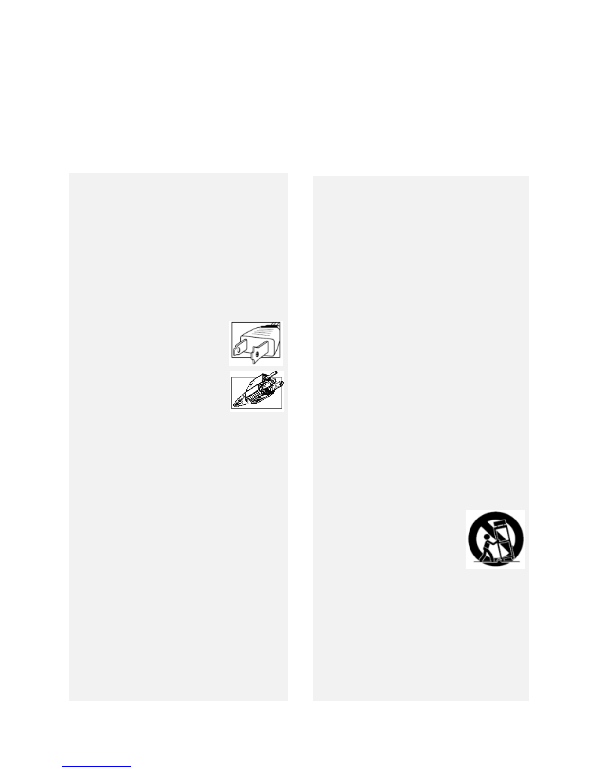
4. Polarization - Do not defeat the safety purpose of the
polarized or grounding-type plug.
A polarized plug has two blades with
one wider than the other.
A grounding type plug has two blades
and a third grounding prong.
The wide blade or the third prong are
provided for your safety.
If the provided plug does not fit into
your outlet, consult an electrician for
replacement of the obsolete outlet
5. Power Sources - This video product should be
operated only from the type of power source
indicated on the marking label. If you are not sure of
the type of power supply to your location, consult
your video dealer or local power company. For video
products intended to operate from battery power, or
other sources, refer to the operating instructions.
6. Overloading - Do not overload wall outlets of
extension cords as this can result in the risk of fire
or electric shock. Overloaded AC outlets, extension
cord s, fra yed po wer co rds, dama ged o r crac ked wi re
insulation, and broken plugs are dangerous. They
may result in a shock or fire hazard. Periodically
examine the cord, and if its appearance indicates
damage or deteriorated insulation, have it replaced
by your service technician.
7. Power-Cord Protection - Power supply cords should
be routed so that they are not likely to be walked on
or pinched by items placed upon or against them,
paying particular attention to cords at plugs,
convenience receptacles, and the point where they
exit from the video product.
8. Ventilation - Slots and openings in the case are
provided for ventilation to ensure reliable operation
of the video product and to protect it from
overheating. These openings must not be blocked or
covered. The openings should never be blocked by
placing the video equipment on a bed, sofa, rug, or
other similar surface. This video product should
never be placed near or over a radiator or heat
register. This video product should not be placed in
a built-in installation such as a bookcase or rack
unless proper ventilation is provided or the video
product manufacturer’s instructions have been
followed.
9. Attachments - Do not use attachments unless
recommended by the video product manufacturer as
they may cause a hazard.
10. Camera Extension Cables – Check the ratin g of your
extension cable(s) to verify compliance with your
local authority regulations prior to installation.
11. Water and Moisture - Do not use this video product
near water. For example, near a bath tub, wash bowl,
kitchen sink or laundry tub, in a wet basement, near
a swimming pool and the like.
Caution: Maintain electrical safety. Power line
operated equipment or accessories connected to
this unit should bear the UL listing mark of CSA
certification mark on the accessory itself and should
not be modified so as to defeat the safety features.
This will help avoid any potential hazard from
electrical shock or fire. If in doubt, contact qualified
service personnel.
12. Accessories - Do not place this
video equipment on an unstable
cart, stand, tripod, or table. The
video equipment may fall, causing
serious damage to the video
product. Use this video product
only with a cart, stand, tripod,
bracket, or table recommended by the manufacturer
or sold with the video product. Any mounting of the
product should follow the manufacturer’s
instructions and use a mounting accessory
recommended by the manufacturer.
vii

Service
13. Servicing - Do not attempt to service this video
equipment yourself as opening or removing covers
may expose you to dangerous voltage or other
hazards. Refer all servicing to qualified service
personnel.
14. Conditions Requiring Service - Unplug this video
product from the wall outlet and refer servicing to
qualified service personnel under the following
conditions.
A. When the power supply cord or plug is
damaged.
B. If liquid has been spilled or objects have fallen
into the video product.
C. If the video product has been exposed to rain
or water.
D. If the video product does not operate normally
by following the operating instructions. Adjust
only those controls that are covered by the
operating instructions. Improper adjustment of
other controls may result in damage and will
often require extensive work by a qualified
technician to restore the video product to its
normal operation.
E. If the video product has been dropped or the
cabinet has been damaged.
Use
19. Cleaning - Unplug the video product from the wall
outlet before cleaning. Do not use liquid cleaners or
aerosol cleaners. Use a damp cloth for cleaning.
20. Product and Cart Combination - Video and cart
combination should be moved with care. Quick stops,
excessive force, and uneven surfaces may cause the
video product and car combination to overturn.
21. Object and Liquid Entry - Never push objects for any
kind into this video product through openings as they
may touch dangerous voltage points or “short-out”
parts that could result in a fire or electric shock.
Never spill liquid of any kind on the video product.
22. Lightning - For added protection for this video
product during a lightning storm, or when it is left
unattended and unused for long periods of time,
unplug it from the wall outlet and disconnect the
antenna or cable system. This will prevent damage
to the video product due to lightning and power line
surges.
F. When the video product exhibits a distinct
change in performance. This indicates a need for
service.
15. Replacement Parts - When replacement parts are
required, have the service technician verify that the
replacements used have the same safety
characteristics as the original parts. Use of
replacements specified by the video product
manufacturer can prevent fire, electric shock or
other hazards.
16. Safety Check - Upon completion of any service or
repairs to this video product, ask the service
technician to perform safety checks recommended
by the manufacturer to determine that the video
product is in safe operating condition.
17. Wall or Ceiling Mounting - The cameras provided
with this system should be mounted to a wall or
ceiling only as instructed in this guide, using the
provided mounting brackets.
18. Heat - The product should be situated away from
heat sources such as radiators, heat registers,
stoves, or other products (including amplifiers) that
produce heat.
viii

General Precautions
FCC CLASS B NOTICE
Note
This equipment has been tested and found to comply with the limits for a Class B digital device, pursuant to
Part 15 of the FCC Rules. These limits are designed to provide reasonable protection against harmful
interference in a residential installation. This equipment generates, uses, and can radiate radio frequency
energy and, if not in-stalled and used in accordance with the instruction, may cause harmful interference to
radio communications.
However, there is no guarantee that interference will not occur in a particular installation. If this equipment
does cause harmful interference to radio or television reception (which can be determined by turning the
equipment on and off), the user is encouraged to try to correct the interference by one or more of the following
measures:
• Reorient or relocate the receiving antenna
• Increase the separation between the equipment and receiver
• Connect the equipment into an outlet on a circuit different from that to which the receiver is
connected
• Consult the dealer or an experienced radio or television technician for assistance
www.lorexcctv.com
1. All warnings and instructions in this manual should be followed.
2. Remove the plug from the outlet before cleaning. Do not use liquid aero
water dampened cloth for cleaning.
3. Do not use this unit in humid or wet places.
4. Keep enough space around the unit for ventilation. Slots and openings in the storage cabinet
should
not be bl
ocked.
5. During lightning storms, or when the unit is not used for a long time, disconnect the power
supply, antenna,
and cables to protect the unit from electrical surge.
sol detergents. Use a
This equipment has been certified and found to comply with the limits regulated by FCC, EMC, and
LVD. There
it is designated to provide reasonable protection against interference and will not
fore,
cause interference with other appliance usage.
However, it is imperative that the user follows this manuals guideline to avoid improper usage
which may result
In order to improve the feature functions and quality of this product,
in damage to the unit, electrical shock and fire hazard injury
the specifications ar
to change without notice from time to time.
e subject
ix

Features
• Stand-alone network 4/8/16 channel
DVR
• Small form factor (11.5" x 1.6"x 7.0")
EDGE
•
• 3D graphics for sharp, color rich, high
• DVI/VGA output for display on PC
• HDMI compatible†
• H.264 compression for efficient file transfer & storage (up to 50% more than MPEG-4)**
• Simultaneous Pentaplex operation (view, record, playback, and remote view and backup)
design for stand alone or VESA
mount (Wall & LCD)
contrast video
monitor or TV with DVI/VGA input (DVI to VGA adapter included)*
• View and record at VGA resolution: up to 640x480 per channel
• Supports up to 1TB "Security Certified" SATA HDD
• "FLEX" IR extender (Remote control does not require line-of-sight)
®
• USB mouse, Internet browser, QuickTime Player
, USB backup
• 4/1 Alarm input/output
• 2-channel audio
• Record on motion detection, schedule or continuous
only
• Email notification of events (8/16-channel
)
• Internet Remote Functions: View, Search & Playback, Backup and Setup‡
®
• Windows Vista
compatible
• Free Lorex DDNS (Dynamic Domain Name System) service keeps you connected anywhere,
all the time
*DVI output only on 8/16-channel models; VGA output only on 4-channel models.
†DVI to HDMI adapter cable required (not included).
**Recording capacity may vary based on recording resolution & quality
‡Requires a high speed Internet connection and router (not included)
Windows Vista is a registered trademark of Microsoft Corporation. Othe
reserve the right to change models, configurations or specifications without notice or liability. Product may not be exactly as shown.
x
, lighting conditions and movement in the scene.
r trademarks are the property of Lorex Technology Inc. We

TABLE OF CONTENTS
Getting Started . . . . . . . . . . . . . . . . . . . . . . . . . . . . . . . . . . . . . . . . . . . . . . . . . 1
Basic Setup . . . . . . . . . . . . . . . . . . . . . . . . . . . . . . . . . . . . . . . . . . . . . . . . . . . . . . . . . . . . . 2
Mount the System . . . . . . . . . . . . . . . . . . . . . . . . . . . . . . . . . . . . . . . . . . . . . . . . . . . . . . . . . . . . . . . . . . . . . 2
Connect the Cameras . . . . . . . . . . . . . . . . . . . . . . . . . . . . . . . . . . . . . . . . . . . . . . . . . . . . . . . . . . . . . . . . . . 2
Connect the Monitor . . . . . . . . . . . . . . . . . . . . . . . . . . . . . . . . . . . . . . . . . . . . . . . . . . . . . . . . . . . . . . . . . . . 2
Connect the Ethernet cable . . . . . . . . . . . . . . . . . . . . . . . . . . . . . . . . . . . . . . . . . . . . . . . . . . . . . . . . . . . . . 2
Connect the Flex-IR Extender . . . . . . . . . . . . . . . . . . . . . . . . . . . . . . . . . . . . . . . . . . . . . . . . . . . . . . . . . . . 2
Front Panel . . . . . . . . . . . . . . . . . . . . . . . . . . . . . . . . . . . . . . . . . . . . . . . . . . . . . . . . . . . . . 3
All models . . . . . . . . . . . . . . . . . . . . . . . . . . . . . . . . . . . . . . . . . . . . . . . . . . . . . . . . . . . . . . . . . . . . . . . . . . . . . . . . . . .3
Rear Panel . . . . . . . . . . . . . . . . . . . . . . . . . . . . . . . . . . . . . . . . . . . . . . . . . . . . . . . . . . . . . . 3
4-channel . . . . . . . . . . . . . . . . . . . . . . . . . . . . . . . . . . . . . . . . . . . . . . . . . . . . . . . . . . . . . . . . . . . . . . . . . . . . . . . . . . .3
Rear Panel . . . . . . . . . . . . . . . . . . . . . . . . . . . . . . . . . . . . . . . . . . . . . . . . . . . . . . . . . . . . . . 4
8-channel . . . . . . . . . . . . . . . . . . . . . . . . . . . . . . . . . . . . . . . . . . . . . . . . . . . . . . . . . . . . . . . . . . . . . . . . . . . . . . . . . . .4
16-channel . . . . . . . . . . . . . . . . . . . . . . . . . . . . . . . . . . . . . . . . . . . . . . . . . . . . . . . . . . . . . . . . . . . . . . . . . . . . . . . . . .4
Mouse Control . . . . . . . . . . . . . . . . . . . . . . . . . . . . . . . . . . . . . . . . . . . . . . . . . . . . . . . . . . 5
Remote Control . . . . . . . . . . . . . . . . . . . . . . . . . . . . . . . . . . . . . . . . . . . . . . . . . . . . . . . . .6
Starting the System . . . . . . . . . . . . . . . . . . . . . . . . . . . . . . . . . . . . . . . . . . . . . 8
Onscreen Display . . . . . . . . . . . . . . . . . . . . . . . . . . . . . . . . . . . . . . . . . . . . . . . . . . . . . . . .8
Using the Split-Screen Selector . . . . . . . . . . . . . . . . . . . . . . . . . . . . . . . . . . . . . . . . . . . 12
Setting the Date and Time . . . . . . . . . . . . . . . . . . . . . . . . . . . . . . . . . . . . . . . 13
Recording. . . . . . . . . . . . . . . . . . . . . . . . . . . . . . . . . . . . . . . . . . . . . . . . . . . . . 14
Event Recording . . . . . . . . . . . . . . . . . . . . . . . . . . . . . . . . . . . . . . . . . . . . . . . . . . . . . . . . 14
Recording Audio . . . . . . . . . . . . . . . . . . . . . . . . . . . . . . . . . . . . . . . . . . . . . . . . . . . . . . . .14
Playback. . . . . . . . . . . . . . . . . . . . . . . . . . . . . . . . . . . . . . . . . . . . . . . . . . . . . . 15
Playback Markers . . . . . . . . . . . . . . . . . . . . . . . . . . . . . . . . . . . . . . . . . . . . . . . . . . . . . . 16
Event List . . . . . . . . . . . . . . . . . . . . . . . . . . . . . . . . . . . . . . . . . . . . . . . . . . . . . 17
Channel Filter . . . . . . . . . . . . . . . . . . . . . . . . . . . . . . . . . . . . . . . . . . . . . . . . . . . . . . . . . . 17
Smart Search . . . . . . . . . . . . . . . . . . . . . . . . . . . . . . . . . . . . . . . . . . . . . . . . . . . . . . . . . .18
Event Details . . . . . . . . . . . . . . . . . . . . . . . . . . . . . . . . . . . . . . . . . . . . . . . . . . . . . . . . . . . 18
Searching for Recorded Data . . . . . . . . . . . . . . . . . . . . . . . . . . . . . . . . . . . . . . . . . . . . . 19
Managing Passwords . . . . . . . . . . . . . . . . . . . . . . . . . . . . . . . . . . . . . . . . . . . 21
Using the Password Wheel . . . . . . . . . . . . . . . . . . . . . . . . . . . . . . . . . . . . . . . . . . . . . . . 21
Enabling and Disabling Passwords . . . . . . . . . . . . . . . . . . . . . . . . . . . . . . . . . . . . . . . . 21
Changing Passwords . . . . . . . . . . . . . . . . . . . . . . . . . . . . . . . . . . . . . . . . . . . . . . . . . . . . 22
Using the Main Menu . . . . . . . . . . . . . . . . . . . . . . . . . . . . . . . . . . . . . . . . . . . 23
Camera . . . . . . . . . . . . . . . . . . . . . . . . . . . . . . . . . . . . . . . . . . . . . . . . . . . . . . . . . . . . . . . 24
xi

Setup . . . . . . . . . . . . . . . . . . . . . . . . . . . . . . . . . . . . . . . . . . . . . . . . . . . . . . . . . . . . . . . . . 24
Record . . . . . . . . . . . . . . . . . . . . . . . . . . . . . . . . . . . . . . . . . . . . . . . . . . . . . . . . . . . . . . . . 25
Schedule . . . . . . . . . . . . . . . . . . . . . . . . . . . . . . . . . . . . . . . . . . . . . . . . . . . . . . . . . . . . . . . . . . . . . . . . . . . 27
Format HDD . . . . . . . . . . . . . . . . . . . . . . . . . . . . . . . . . . . . . . . . . . . . . . . . . . . . . . . . . . . . . . . . . . . . . . . . . 28
Storage Calculator . . . . . . . . . . . . . . . . . . . . . . . . . . . . . . . . . . . . . . . . . . . . . . . . . . . . . . . . . . . . . . . . . . . . . . . . . . .28
Alarm . . . . . . . . . . . . . . . . . . . . . . . . . . . . . . . . . . . . . . . . . . . . . . . . . . . . . . . . . . . . . . . . . 28
Motion . . . . . . . . . . . . . . . . . . . . . . . . . . . . . . . . . . . . . . . . . . . . . . . . . . . . . . . . . . . . . . . . . . . . . . . . . . . . . 30
Backup . . . . . . . . . . . . . . . . . . . . . . . . . . . . . . . . . . . . . . . . . . . . . . . . . . . . . . . . . . . . . . . . 31
Formatting the USB Drive . . . . . . . . . . . . . . . . . . . . . . . . . . . . . . . . . . . . . . . . . . . . . . . . . . . . . . . . . . . . . 31
LAN . . . . . . . . . . . . . . . . . . . . . . . . . . . . . . . . . . . . . . . . . . . . . . . . . . . . . . . . . . . . . . . . . . 32
Upgrading Firmware . . . . . . . . . . . . . . . . . . . . . . . . . . . . . . . . . . . . . . . . . . . . . . . . . . . . . . . . . . . . . . . . . . 33
REMOTE ACCESS: DVR Netviewer . . . . . . . . . . . . . . . . . . . . . . . . . . . . . . . . 34
System Requirements . . . . . . . . . . . . . . . . . . . . . . . . . . . . . . . . . . . . . . . . . . . . . . . . . . . 34
Configuring QuickTime . . . . . . . . . . . . . . . . . . . . . . . . . . . . . . . . . . . . . . . . . . . . . . . . . . 35
Using DVR Netviewer . . . . . . . . . . . . . . . . . . . . . . . . . . . . . . . . . . . . . . . . . . . 36
Network User Profiles . . . . . . . . . . . . . . . . . . . . . . . . . . . . . . . . . . . . . . . . . . . . . . . . . . . 36
Logging In to Your System . . . . . . . . . . . . . . . . . . . . . . . . . . . . . . . . . . . . . . . . . . . . . . . . 36
DVR Netviewer Main Screen . . . . . . . . . . . . . . . . . . . . . . . . . . . . . . . . . . . . . . . . . . . . . . 38
Live Viewing . . . . . . . . . . . . . . . . . . . . . . . . . . . . . . . . . . . . . . . . . . . . . . . . . . . . . . . . . . .40
Playback . . . . . . . . . . . . . . . . . . . . . . . . . . . . . . . . . . . . . . . . . . . . . . . . . . . . . . . . . . . . . . 40
Using the Pop-Up Calendar . . . . . . . . . . . . . . . . . . . . . . . . . . . . . . . . . . . . . . . . . . . . . . . 41
Backup . . . . . . . . . . . . . . . . . . . . . . . . . . . . . . . . . . . . . . . . . . . . . . . . . . . . . . . . . . . . . . . . 42
Setup . . . . . . . . . . . . . . . . . . . . . . . . . . . . . . . . . . . . . . . . . . . . . . . . . . . . . . . . . . . . . . . . . 44
Streaming . . . . . . . . . . . . . . . . . . . . . . . . . . . . . . . . . . . . . . . . . . . . . . . . . . . . . . . . . . . . . . . . . . . . . . . . . . 44
Bitrate . . . . . . . . . . . . . . . . . . . . . . . . . . . . . . . . . . . . . . . . . . . . . . . . . . . . . . . . . . . . . . . . . . . . . . . . . . . . . 44
PPPoE . . . . . . . . . . . . . . . . . . . . . . . . . . . . . . . . . . . . . . . . . . . . . . . . . . . . . . . . . . . . . . . . . . . . . . . . . . . . . 45
DDNS . . . . . . . . . . . . . . . . . . . . . . . . . . . . . . . . . . . . . . . . . . . . . . . . . . . . . . . . . . . . . . . . . . . . . . . . . . . . . . 45
System Status . . . . . . . . . . . . . . . . . . . . . . . . . . . . . . . . . . . . . . . . . . . . . . . . . . . . . . . . . . . . . . . . . . . . . . . 47
Resuming Live Viewing . . . . . . . . . . . . . . . . . . . . . . . . . . . . . . . . . . . . . . . . . . . . . . . . . . . . . . . . . . . . . . . . 47
Mail . . . . . . . . . . . . . . . . . . . . . . . . . . . . . . . . . . . . . . . . . . . . . . . . . . . . . . . . . . . . . . . . . . . . . . . . . . . . . . . . 48
Title . . . . . . . . . . . . . . . . . . . . . . . . . . . . . . . . . . . . . . . . . . . . . . . . . . . . . . . . . . . . . . . . . . . . . . . . . . . . . . . 48
Appendix A: System Specifications . . . . . . . . . . . . . . . . . . . . . . . . . . . . . . . 49
Appendix B: Setting up Local and Remote Viewing . . . . . . . . . . . . . . . . . . 51
Appendix C: Changing Ports On Your System . . . . . . . . . . . . . . . . . . . . . . . 61
Appendix D: Connecting Motion / Alarm Devices . . . . . . . . . . . . . . . . . . . . 65
Appendix E: Full Connectivity Diagram . . . . . . . . . . . . . . . . . . . . . . . . . . . . 66
Appendix F: Replacing the Hard Drive . . . . . . . . . . . . . . . . . . . . . . . . . . . . . 67
Appendix G: Connecting Audio . . . . . . . . . . . . . . . . . . . . . . . . . . . . . . . . . . . 70
Appendix H: Playing Saved Video . . . . . . . . . . . . . . . . . . . . . . . . . . . . . . . . . 71
Appendix I: Taking Screenshots . . . . . . . . . . . . . . . . . . . . . . . . . . . . . . . . . . 72
Troubleshooting . . . . . . . . . . . . . . . . . . . . . . . . . . . . . . . . . . . . . . . . . . . . . . . 74
xii

GETTING STARTED
POWER SUPPLY
INSTRUCTION MANUAL
QUICKSTART GUIDE
DOCUMENTATION CD
REMOTE CONTROL*
MOUNTING KIT
FLEX-IR EXTENDER
EDGE DVR
USB MOUSE
*Remote control included with the system may vary depending on model.
**Only included with 8 and 16-channel models.
ETHERNET CABLE
DVI / VGA ADAPTER**
The system comes with the following components:
HARD DRIVE SIZE, NUMBER OF CHANNELS, AND CAMERA CONFIGURATION MAY VARY
BY MODEL. PLEASE REFER TO YOUR PACKAGE FOR SPECIFIC DETAILS.
CHECK YOUR PACKAGE TO CONFIRM THAT YOU HAVE RECEIVED THE COMPLETE SYSTEM,
INCLUDING ALL COMPONENTS SHOWN ABOVE.
1
Getting Started
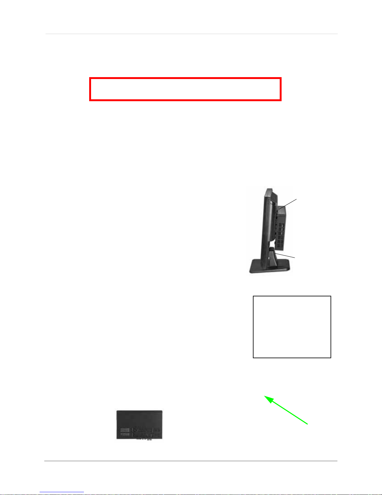
ATTENTION: You can only mount the system to an LCD
monitor that has a VESA mount and an independent stand.
Figure 1.3 Connect the Flex IR extender
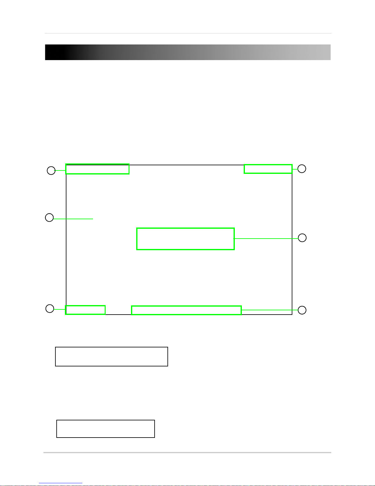
Figure 1.1 Mount the system to the
monitor
Figure 1.2 Connect the Ethernet cable
Figure 1.0 Mounting holes on bottom panel
VESA mount
Independent
stand
Vertical (wall mount)
Horizontal (table, desk)
Basic Setup
The system is designed to mount to the back of most LCD monitors with a VESA mount. If desired,
you can mount it to a wall or leave the system in a standard horizontal position.
1. Mount the System
a. Screw the provided mounting screws into the two top
holes in the rear panel of your LCD monitor. Make sure
the screws are only 3/4 of the way in; this will allow
sufficient clearance to hang the system.
b. Carefully place the system (front panel facing up) over
the screws
2. Connect the Cameras
a. Connect BNC cameras to the BNC ports on the rear
panel.
and slide down into place.
3. Connect the Monitor
a. Connect the VGA / DVI cable (not included) from your LCD
monitor to the VGA port (4 CH) / DVI port (8/16 CH
the rear panel of the system.
4. Connect the Ethernet cable
a. Connect the included Ethernet cable to the LAN port on
the rear panel of system; connect the other end of the
Ethernet cable to an empty LAN port on your router (not
included).
5. Connect the Flex-IR Extender
a. Connect the Flex-IR extender to the port on the rear
panel of the DVR. Position the Flex-IR extender near the
front of your monitor, or where it will receive a clear
signal from the remote control. Use a piece of
double-sided tape (included) to help secure the Flex-IR
Extender.
NOTE:
It may be necessary if there is not a clear line-of-sight between the
DVR and the remote control.
The Flex-IR Extender is not required for normal operation.
only
) on
Optional Mounting
2
Front Panel
1
2
3
4
12
3
6
7
8
9
4
5
10
All models
1. IR Receiver: Internal IR receiver for the remote control.
2. USB port: Connect
website).
3. Power Indicator: LED indic
4. HDD Indicator: LED indica
LED pulses red.
a USB flash drive for data backup and firmware updates (download from
at
or for system power. When system is powered on, LED is lit red.
tor for internal hard drive. When in continuous recording mode,
Getting Started
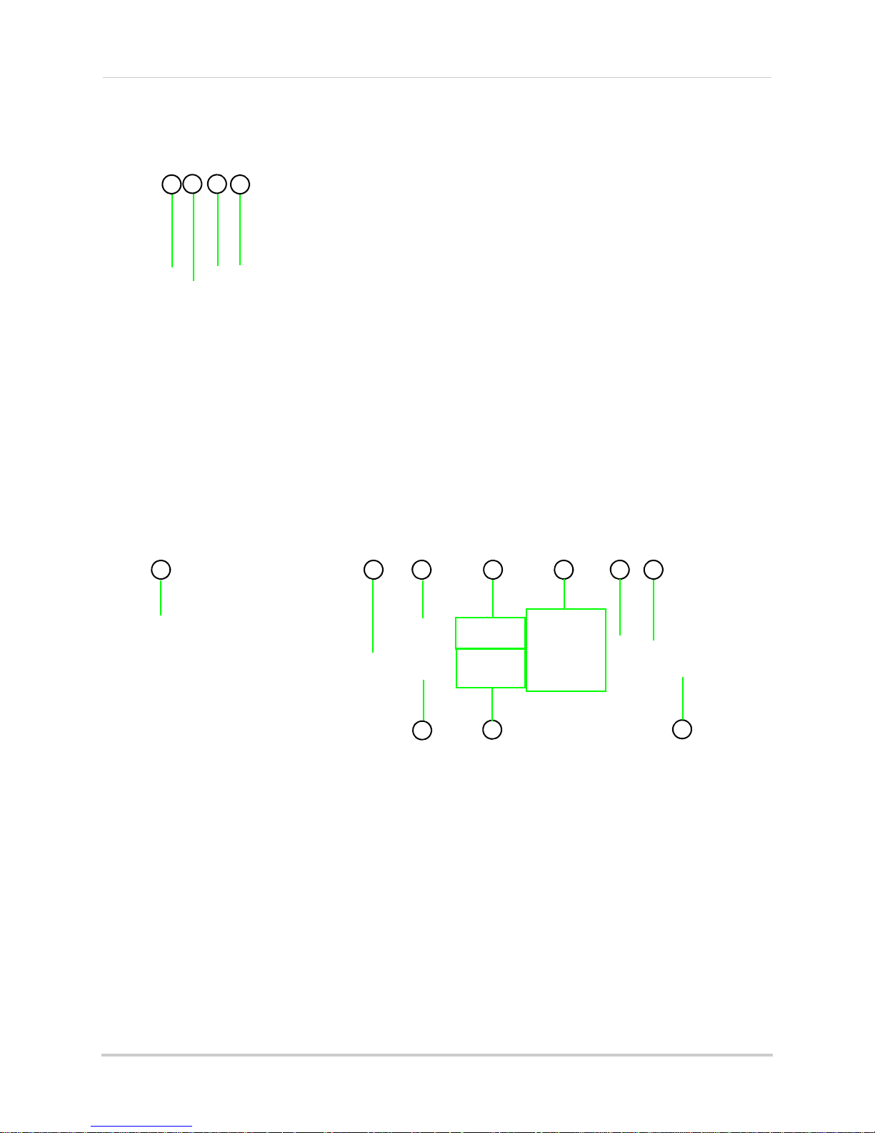
Rear Panel
4-channel
1. Exhaust slots: Slots to let heat escape from the internal hard drive.
proper ventilation.
2. DC 12V: Port f
3. Alarm I/O: Input/output port f
4. Audio In: Input
5. Video In: BNC input ports f
6. USB Port: Port f
7. LAN: Networking port f
8. VGA: Port to connect a VGA monitor (not included)
9. Audio Out: Output f
10. IR: Port for the Flex-IR Extender.
or 12V DC 2.5 A power adapter (included).
or alarm / relay (D-sub 9 connector required—not included).
ports for audio enabled cameras.
or 4 BNC cameras.
or a USB mouse.
or a 10/100 Base-T RJ-45 network cable (included).
or two audio channels.
11
Do not block
. Allow for
3
Getting Started
3
4
1 2
8
5
6
7
9
10
5
8
3
1 2
4
6
10
7
9
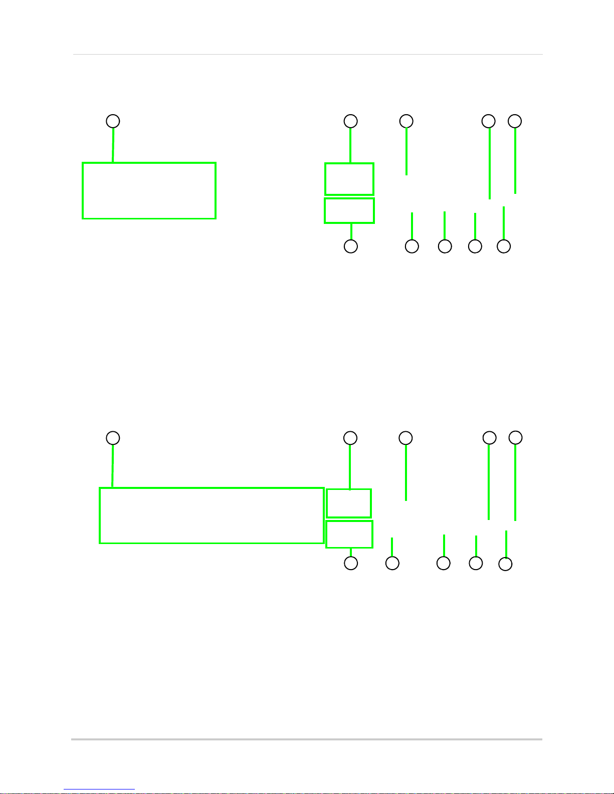
Rear Panel
8-channel
1. Video In: BNC input ports for eight BNC cameras.
2. Audio In: Input
3. Alarm I/O: Input/output port f
4. Audio Out: Output f
5. DVI: Port to connect a DVI monitor (not included).
6. LAN: Networking port f
7. IR: Port for the Flex-IR Extender.
8. USB Port: Port f
9. DC 12V: Port f
10. GND: Ground hole.
ports for audio enabled cameras.
or alarm / relay (D-sub 9 connector required—not included).
or two audio channels.
or a 10/100 Base-T RJ-45 network cable (included).
or a USB mouse.
or 12V DC 2.5 A power adapter (included).
16-channel
1. Video In: BNC input ports for 16 BNC cameras.
2. Audio In: Input
3. Alarm I/O: Input/output port f
4. Audio Out: Output f
5. DVI: Port to connect a DVI monitor (not included).
6. LAN: Networking port f
7. IR: Port for the Flex-IR Extender.
8. USB Port: Port f
9. DC 12V: Port f
10. GND: Ground hole.
ports for audio enabled cameras.
or alarm / relay (D-sub 9 connector required—not included).
or two audio channels.
or a 10/100 Base-T RJ-45 network cable (included).
or a USB mouse.
or 12V DC 2.5 A power adapter (included).
4
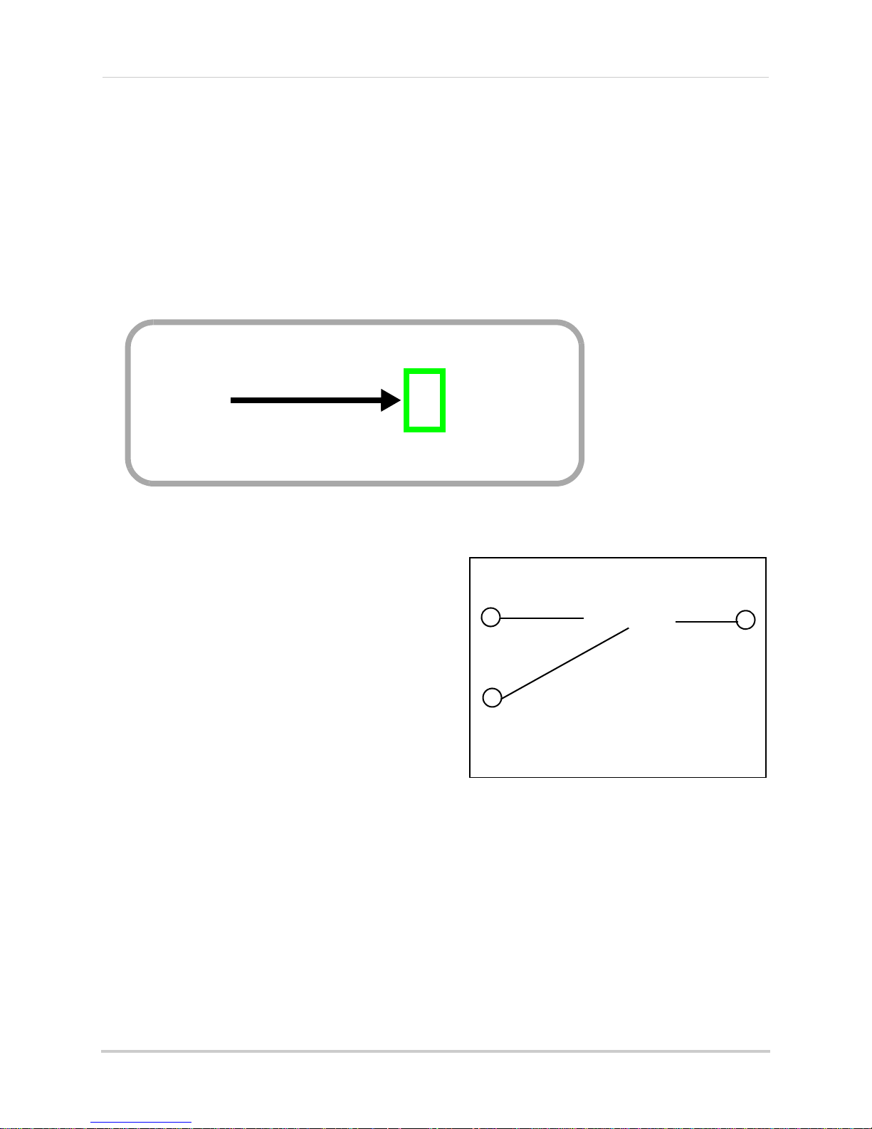
Mouse Control
Figure 2.0 Connect a USB mouse to the USB port on the rear panel
1
2
3
The mouse is the primary input device for navigating system menus.
Getting Started
NOTE:
mouse input.
Unless otherwise noted, all system functions described in this manual are achieved through
To use a mouse with the system:
1. Connect a USB mo
NOTE:
connect a USB flash drive to the USB port on the rear panel.
Only the USB port on the front panel is designed for data backup to a USB flash drive. Do not
use to the USB port on rear panel of the system.
2. Use the mouse buttons to perform the following:
• Left-Button: Click to sel
ect a menu option;
while in Split-Screen mode (Live View or
Playback), click on a channel to view the
selected channel in full-screen.
• Right-Button: Click to return to previous menu;
exit menus/modes.
3. Scroll-Wheel: Scr
oll up/do
in selected menu options; position markers in
playback bar.
n to change values
w
Figure 2.1 Mouse button operation
5
Getting Started
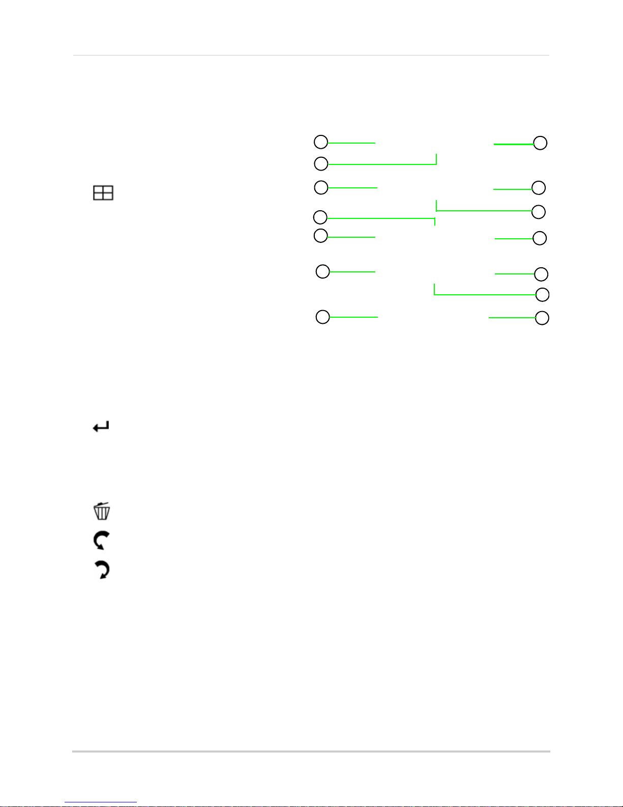
Figure 3.0 Remote Control
1
2
3
4
5
6
Remote Control
*
The remote control is the secondary input device
for navigating the system’s graphical user
interface.
NOTE:
system differs from figure 3.0, please see page 6
for details.
If the remote control included with your
To use the remote control:
1. LIST: Open the Event List menu.
2.
OSD: Show/hide the on-screen display.
3. Primary controls:
• MENU: Opens the system main menu.
• : Press to open the Split-Screen Selection
menu (
8 / 16-channel only
From full-screen single channel view, changes
display
model only
• S/
• X/FWD: Move cursor in menus right; during
playback, increase forward playback speed (5X,
15X, 60X).
• W/
playback, increase reverse playback speed (5X,
15X, 60X)
•
/: Start/pause forward playback.
• T/CH-: Move cursor in menus down; Channel down.
ESC: Go back / exit menus.
•
• : Confirm menu selections.
view to Quad split-screen (
)
CH+: Move cursor in menus up; Channel Up.
REW: Move cursor in menus left; during
).
4-channel
4. : While in Event List menu, press to delete a selected event (no confirm or undo).
5.
: During Live Mode and Playback, press to switch between cameras (4-channel); Press to
take a screenshot of the main display—USB flash drive mus
only).
6. Increase/Decrease buttons:
• : Increase the value of selected menu option.
• : Decrease the value of selected menu option.
*Remote control included with the system may vary depending on model.
6
t be connected (8/16-channel
Getting Started
1
2
3
4
5
6
7
9
10
11
12
13
14
8
Figure 3.1 Remote Control
Remote Control (cont’d.)
*
The remote control is the secondary input
device for navigating the system’s graphical
user interface.
To use the remote control:
1. MENU: Opens the system main menu.
2. : From full-screen single channel
view, changes display view to Quad
split-screen (
4-channel only
).
3. S/CH+: Move cursor in menus up;
Chan
nel Up.
4. X/FWD: Move cursor in menus right;
during playback, incr
ease forward
playback speed (5X, 15X, 60X).
5. W/REW: Move cursor in menus left;
during playback,
increase reverse
playback speed (5X, 15X, 60X)
/: Start/pause forward playback.
6.
7. T/CH-: Move cursor in menus down;
nel down.
Chan
8. : Confirm menu selections.
9. ESC: Go back / exit menus.
10. OSD: Show/hide the on-scr
11. LIST: Open the Ev
ent List menu.
een display.
12. : While in Event List menu, press to delete a selected event (no confirm or undo).
13. : Decrease value of selected menu option.
14. : Increase value of selected menu option.
*Remote control included with the system may vary depending on model.
7
STARTING THE SYSTEM
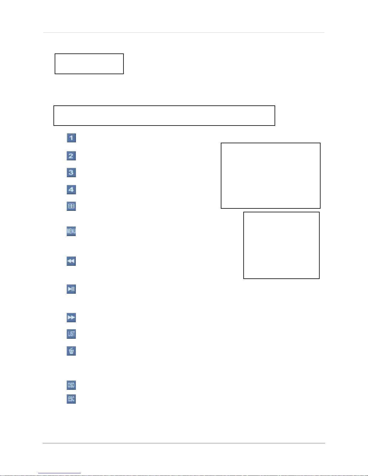
Figure 4.0 Live viewing with on-screen display (4-channel model)
2
4
5
6
1
3
To power the system ON:
• Connect the power cable to the DC 12V port on the rear panel of the system
At startup, the system performs a basic system check and runs an initial loading sequence. After
few moments, the system loads a
a
NOTE: Make sure all cameras and cables are properly connected prior to powering on the
tem.
sys
live display view (
Onscreen Display
4-channel
Live Mode
).
1. System Status Bar: Displays mode, password type, recording mode, language, and status of
devices (HDD and USB).
2. Display: Fu
Playback modes; if cameras are disconnected, channels display a blue screen with the text,
"VLOSS."
3. HDD Status: Display
pre-installed hard drive. For example, 250 GB.
8
ll-screen single channel and Quad split-screen available in Live Viewing and
s th
e recording space consumed on the hard disk (%) and the size of the
Starting the System
Figure 4.1 Single channel and Quad (4-channel
model)
4. Camera Status: Displays channel number, recording status, frame rate, and video quality.
5. Date/Time: Displays th
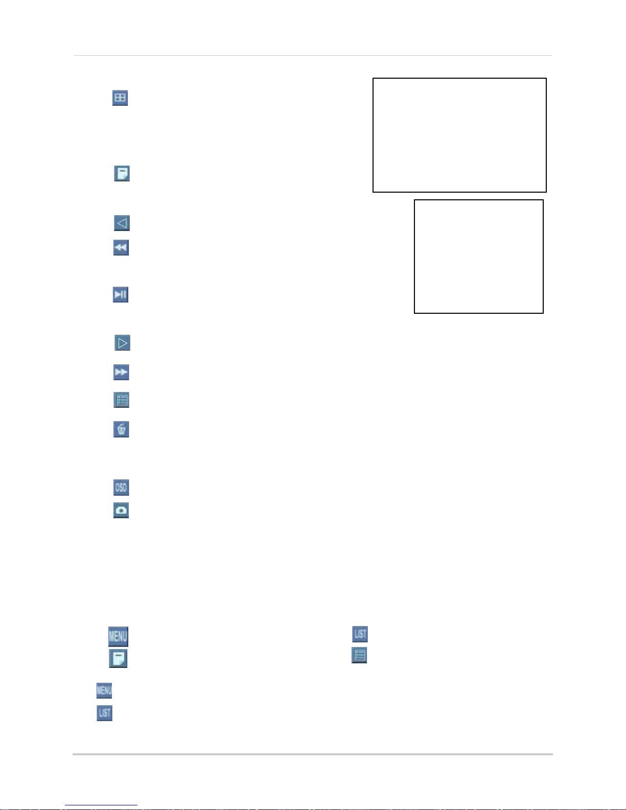
6. Toolbar: Primar
y control input for the user interface:
e date and time on the system.
• : Click to view channel 1 in full-screen.
• : Click to view channel 2 in full screen.
• : Click to view channel 3 in full screen.
• : Click to view channel 4 in full screen.
• : Click to view Quad split-screen mode (Live
View and Playback modes).
• : Click to open the system Main Menu. See
“Using the Main Menu” on page 23.
• : While in Playback mode, click to increase
reverse playback speed (5X, 15X, 60X).
• : From Live View, click to open Playback
Mode; click to pause/play video.
• : While in Playback mode, click to increase f
orward playback speed
• : Click to open the Event List menu. See “Event List” on page 17.
• : From the Event List menu, click to delete a selected video file.
NOTE:
undo the action.
Be careful when clicking the Trash icon—there is no confirmation for deletion and you
• : Click to show/hide the on-screen display (OSD).
• : Click to return to the previous menu, and/or quit menus/modes.
(5X, 15X, 60X).
cannot
9
Starting the System
Figure 4.2 Live viewing with onscreen display (16-channel model shown)
1
6
3
2
4
5
8/16-channel
1. Display Screen: Shows live and recorded video—single, quad, and split-screen (16-split on
only
16-channel model
).
2. Camera Number/Title: You can set the display to show the Camera Number, Title, or show
no title.
3. Channels:
Displays channels
on the system. If Motion Detection is enabled, active channel
will flash red.
4. Date/Time: Displays th
5. HDD Status: Displays th
pre-installed hard drive. For example, 250 GB.
6. Toolbar: Primar
y control input for the user interface (certain buttons will not be available at
all times):
e date and time on the system.
e recording space consumed on the hard disk (%) and the size of the
10
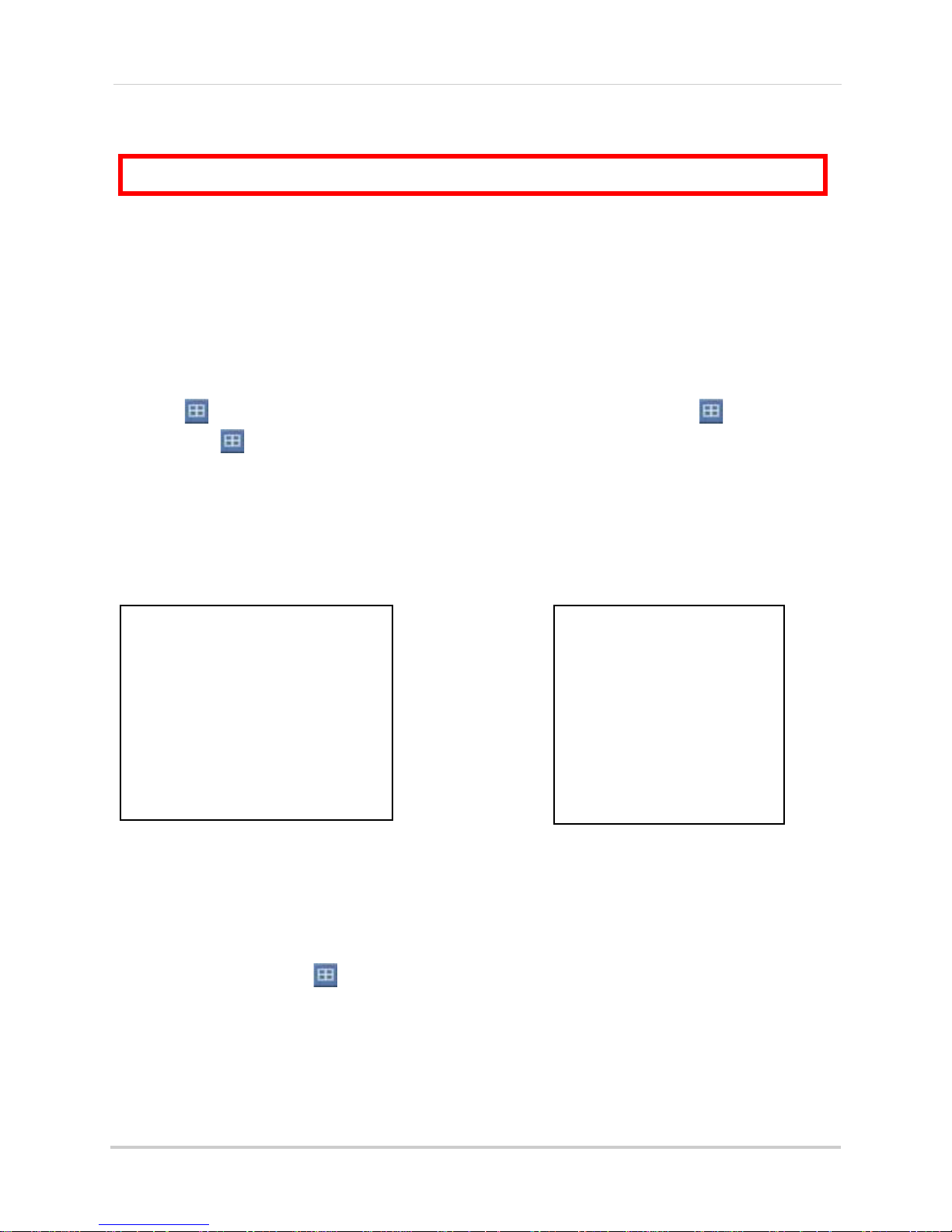
• : Click to open the Split-Screen Selector; from
Figure 4.3 Single channel and Quad (8/
16-channel model)
Main Menu
• : 4-channel
•
: 8/16-channel
Event List
• : 4-channel
• : 8/16-channel
full-screen (Live Mode only), click once to
view quad, click again to open Split-Scr
een
Selector. See “Using the Split-Screen
Selector” on page 12.
• : Click to open the system Main Menu. See
“Using the Main Menu” on page 23.
• : Click to select a menu option (left).
• : Playback mode only—click to increase
reverse playback speed (5X, 15X, 60X).
• : From Live View, click to open Playback Mode;
click to pause/play video.
Starting the System
• : Click to select a menu option (right).
• : While in Playback mode, click to increase f
orward playback speed
(5X, 15X, 60X).
• : Click to open the Event List menu. See “Event List” on page 17.
• : From the Event List menu, click to delete a selected video file.
NOTE:
undo the action.
Be careful when clicking the Trash icon—there is no confirmation for deletion and you
cannot
• : Click to show/hide the on-screen display (OSD).
• : Click to take a snapshot of the active display (liv
NOTE:
on page 72.
USB flash drive must be connected. For more details, see “Appendix I: Taking Screenshots”
e viewing or playback)
Icons
Depending on your model, the Main Menu and Event List icons may look like one of the following:
The
The
icon will be used throughout this manual.
icon will be used throughout this manual.
11
Starting the System
ATTENTION: Split-Screen Selector is only available on
8/16-channel models only
.
Figure 4.4 Split-Screen Selector (8-channel)
Figure 4.5 Split-Screen Selector (16-channel)
Using the Split-Screen Selector
If your system has 8/16-channels, you must choose a split-screen configuration using the
Split-Screen Selector built into the system’s interface. The Split-Screen Selector allows you to
choose the grid configuration for the main display during live viewing and playback: quad, 9-split,
only
or 16-split (16-channel
Live Viewing
To use the Split-Screen Selector:
1. Click to open the Split-Screen Selector. If you are in full-screen, click to view quad,
).
then click again to open the Split-Screen Selector. G
onscreen.
2. Click a grid configuration for live viewing:
•
8-channel
remain blacked out).
•
16-channel
or 16-split (CH1~16).
: Choose from quad (CH1~4, CH5~9) or 9-split (CH1~8; the bottom-right square will
: Choose from quad (CH1~4, CH5~9, CH9~12, CH13~16), 9-split (CH1~9, CH10~2),
onfigurations
rid c
appear in circles
Playback
To use the Split-Screen Selector:
1. During playback, click at anytime to open the Split-Screen Selector.
NOTE:
2. Click a grid configuration for playback.
12
The Split-Screen Selector will open even if you are viewing playback in full-screen.
SETTING THE DATE AND TIME
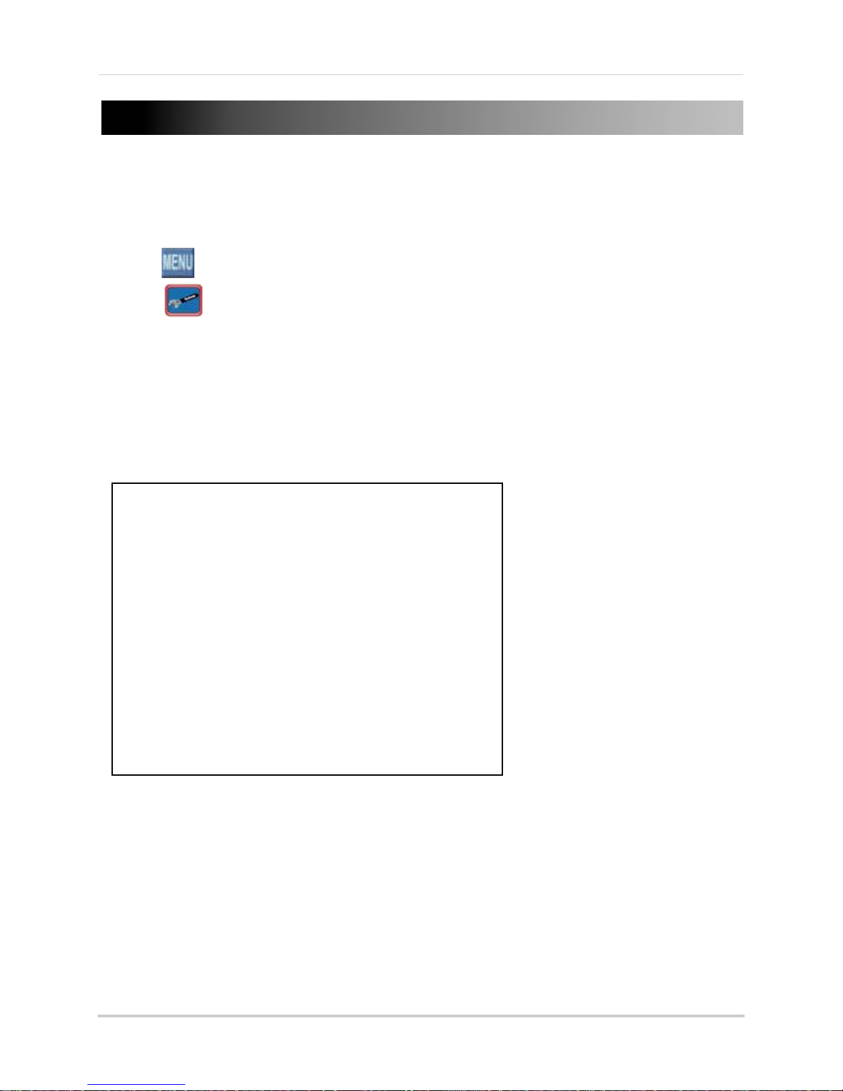
Figure 5.0 Clock menu
It is highly recommended to immediately set the date and time when first setting up your system.
To set the date and time:
1. Click
2. Click
3. Click Date/Time Setup and configure the following options:
• Date Mode: Use the scr
• Date: Use the scroll wheel to manually enter the date.
• Time: Use the scroll wheel to manually enter the time.
4. Click Exit/
5. Right-click to exit until all menus are closed. The date and
bottom-left corner of the screen.
to open the Main Menu.
to open the Setup menu.
oll wheel to select Y/M/D, D/M/Y, or M/Y/D.
Update. The new date and time are saved; the system returns to the Setup menu.
time will appear on the
13

RECORDING
By default, the system is set to immediately record video from connected cameras in Continuous
Record Mode.
You can set the system to stop recording once the hard drive is full, or to continually record by
overwr
iting previously recorded data.
Event Recording
The system includes three modes of event recording:
For more details, see “Record” on page 25.
• Motion: The syst
• Alarm: The system records when an alarm or sensor is triggered.
• Video Loss: The system records when a camera is disconnected or suffers video
loss. The system employs a pre-record function to capture video seconds before
the video loss occurred.
em records when motion is detected by the affected camera.
Recording Audio
The system can record two audio channels. You must have audio enabled cameras connected to
the system in order to use this function.
14
PLAYBACK
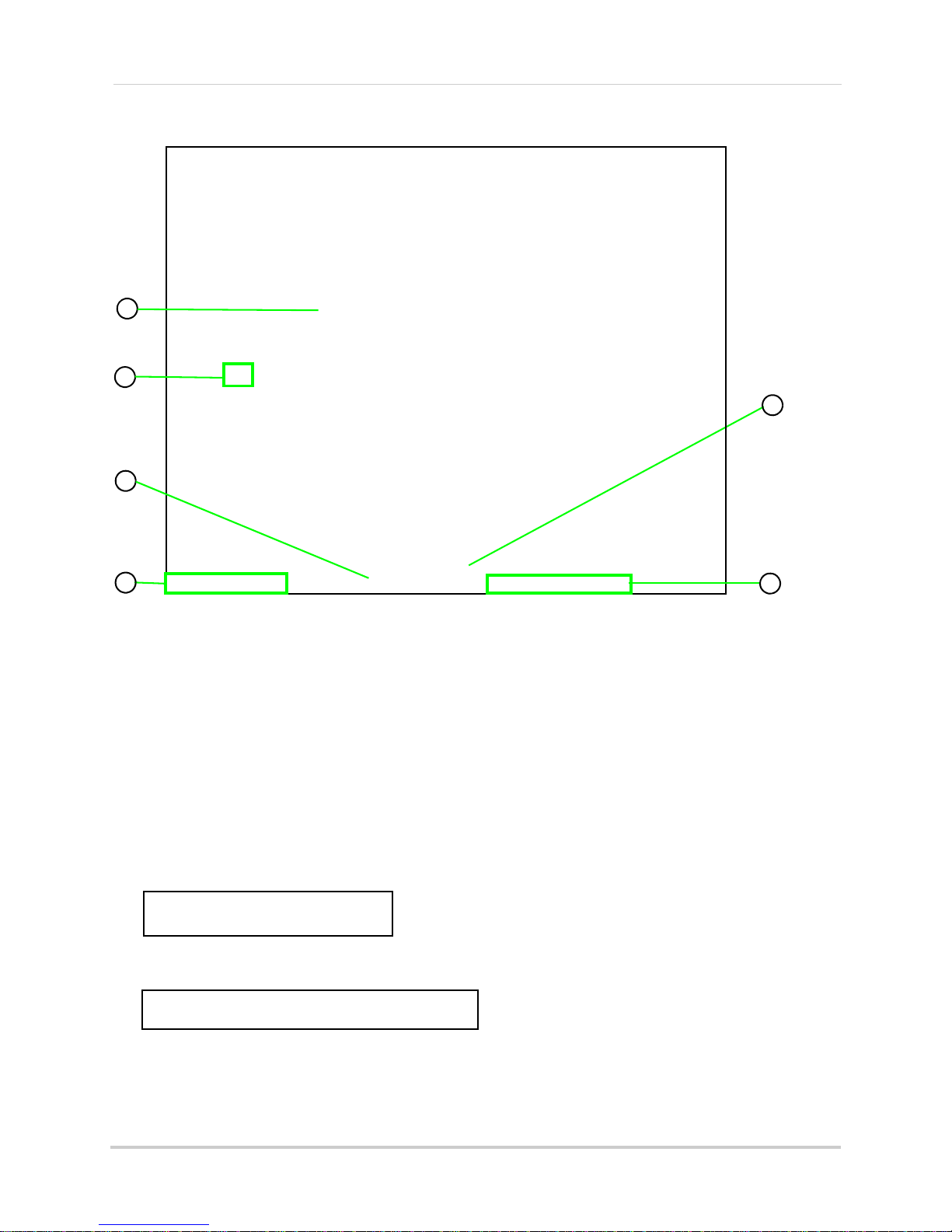
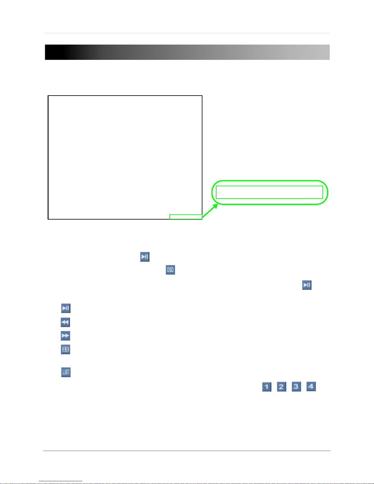
Figure 6.0 Playback display view
The playback time appears in the bottom-right
corner of the screen.
View recorded video on the system through playback mode.
To begin playback:
1. From the main screen, click
NOTE:
If toolbar is not visible, first click .
. Playback mode opens.
2. Select and change the date, month, year, time, and/or frame for playback and click .
3. During playback, you have access to the following:
• : Click to pause playback; press again to resume playback.
• : Click to increase reverse playback speed (5X, 15X, 60X).
• : Click to increase forward playback speed (5X, 15X, 60X).
• : Click to open the Split-Screen Selector (8/16-channel
only
Quad mode (4-channel
: Click to open the Event List menu. See “Playback Mode” on page 20.
•
)
4. Click any channel to view the selected channel in full-screen; or click
only
(4-channel model
).
only
); Click to view playback in
, , ,
5. Click anywhere in the playback bar to set a playback marker. Playback Markers can be used
for faster searching in the Event List. See “Playback Markers” on page 16.
6. Right-click anywhere on the screen to exit.
15
 Loading...