

Page 1

www.lorexcctv.com
LOREX ECO
™
H.264 NETWORK READY
DIGITAL VIDEO SURVEILLANCE RECORDER
INSTRUCTION MANUAL
English Version 2.0
MODEL:
LH100 SERIES
Copyright © 2009 Lorex Technology Inc.
www.lorexcctv.com
Page 2
Thank you for purchasing the LH108 Series Digital Video Surveillance Recorder.
This manual refers to the following models:
• LH104 (4-channel)
• LH108 (8-channel)
To learn more about this product and to learn about our complete range of accessory
products, please visit our website at:
www.lorexcctv.com
CAUTION
RISK OF ELECTRIC SHOCK
DO NOT OPEN
CAUTION: TO REDUCE THE RICK OF ELECTRIC SHOCK DO NOT
REMOVE COVER. NO USER SERVICABLE PARTS INSIDE.
REFER SERVICING TO QUALIFIED SERVICE PERSONNEL.
The lightning flash with arrowhead symbol, within an equilateral
triangle, is intended to alert the user to the presence of uninsulated
"dangerous voltage" within the products ' enclosure that may be of
sufficient magnitude to constitute a risk of electric shock
The exclamation point within an equilateral triangle is intended to
alert the user to the presence of important operating and
maintenance (servicing) instructions in the literature accompanying
the appliance.
WARNING: TO PREVENT FIRE OR SHOCK HAZARD, DO NOT
EXPOSE THIS UNIT TO RAIN OR MOISTURE.
CAUTION: TO PREVENT ELECTRIC SHOCK, MATCH WIDE BLADE
OF THE PLUG TO THE WIDE SLOT AND FULLY INSERT.
Page 3
B E F O R E Y O U S T A R T
THIS PRODUCT MAY REQUIRE PROFESSIONAL INSTALLATION
LOREX IS COMMITTED TO FULFILLING YOUR SECURITY NEEDS
• We have developed user friendly products and documentation.
Please read the Quick Start Guide and User Manual before you
install this product.
• Consumer Guides and Video Tutorials are available on our web
site at www.lorexcctv.com/support
• If you require further installation assistance, please visit
www.lorexcctv.com/installation or contact a professional
installer.
• Please refer to the “Need Help” insert for technical support and
customer care information.
• Please note that once the components of this product have been
unsealed, you cannot return this product directly to the store
without the original packaging.
www.lorexcctv.com
Page 4

AVANT DE
A N T E S D E
COMMENCER
CE PRODUIT POURRAIT EXIGER UNE
INSTALLATION PROFESSIONNELLE
LOREX S’ENGAGE À SATISFAIRE
VOS BESOINS SÉCURITAIRES
• Veuillez lire le guide de démarrage rapide et le
mode d’emploi avant d’installer ce produit.
• Les guides du consommateur et les séances
de tutorat vidéo sont disponibles sur l’Internet en
visitant www.lorexcctv.com/support
• Si vous avez besoin de l’aide pour l’installation,
E M P E Z A R
ESTE PRODUCTO PUEDE EXIGIR UNA
INSTALACIÓN PROFESIONAL
LOREX SE COMPROMETE A SATISFACER
SUS NECESIDADES EN SEGURIDAD
• Favor de leer la guía de instalación rápida y la
guía del usuario antes de instalar este producto.
• Puede conseguir las guías del consumidor y
los cursos en enseñanza video sobre el Internet
visitando www.lorexcctv.com/support
• Si necesita ayuda para la instalación, visite
veuillez visiter www.lorexcctv.com/installation
ou contactez un spécialiste en installation
• Veuillez référer à l’insert “Need Help” pour
ob¬tenir de l’information sur le service à la cli-
entèle et le support technique
• Veuillez constater qu’une fois que les
com¬posantes de ce produit ont été retirées de
l’emballage, vous ne pourrez plus retourner ce
produit directement au magasin.
www.lorexcctv.com/installation o contacte un
especialista en instalaciones
• Favor de referir al documento “Need Help” para
obtener información acerca del servicio al cliente
y al soporte técnico
• Favor de notar que una vez que los compo-
nentes de este producto han sido removidos del
embalaje, no podrá devolver este producto di-
rectamente a la tienda
w w w . l o r e x c c t v . c o m
Page 5

NEED HELP?
CONTACT US FIRST
DO NOT RETURN THIS PRODUCT TO THE STORE
Please make sure to register your product at www.lorexcctv.com to receive product updates and information
3 EASy WAyS TO CONTACT US:
Online:
Pr od u ct S up po r t is a v ai la bl e 2 4/ 7 in c lu di ng pr od uc t
in fo r ma ti on , u se r ma n ua ls , q ui ck s ta r t up g u id es a nd FA Q’ s
at w ww.lo rexcc tv.co m/sup port
To o r de r ac ce s so ri es , v is it
www .lor excct v.com
By Email:
Te ch n ic al S up p or t (f o r te ch n ic al /i ns t al la ti o n is su es )
sup port @lore xcorp .com
Cu st o me r Ca re (f or w a rr an ty an d ac ce s so ry s a le s)
cus tome rserv ice@l orexc orp.c om
Cu st o me r Fe ed b ac k
inf o@lo rexco rp.co m
By Phone:
NOR TH A MERIC A: 1- 888-4 25-67 39 (1 -888- 42-LO REX)
MEX ICO: 1-80 0-514 -6739
INT ERNA TIONA L: + 800-4 25-67 39-0
(Ex amp le: Fr om the UK , d ial 00 in ste ad of +)
Te ch n ic al S up p or t (f o r te ch n ic al /i ns t al la ti o n is su es )
Pr es s o pt io n 1 f or E n gl is h, an d th en pr es s o pt io n 1
OR
Cu st o me r Ca re (f or w a rr an ty an d ac ce s so ry s a le s)
Pr es s o pt io n 1 f or E n gl is h, an d th en pr es s o pt io ns 2 to 5
Page 6

NECESITA AYUDA
VOUS AVEZ BESOIN
D’AIDE?
COMUNÍQUESE PRIMERO
CON NOSOTROS
NO DEVUELVA ESTE PRODUCTO A LA TIENDA
Cerciór ese de p or favor colocar su p roducto en www.
lorexcc tv.com/r egistrat ion para reci bir actu alizacio nes y l a inform ación de l produc to
3 maneras sencillas de comunicarse
con nosotros:
www
En línea:
apoyo al producto disponible 24/7 incluyendo información d el producto, manuales para el usuario, guías
de inici o rápido y preguntas más frecuentes en
www.lorexcctv.com/support
Para col ocar pedidos de accesorios, visite
www.lorexcctv.com
NE RETOURNEZ PAS CE PRODUIT AU MAGASIN
Veuille z veille r à enre gistrer votre produit à www.
lorexcc tv.com/r egistrat ion pour rece voir des mises à
jour et l’infor mation d e produi t
3 façons faciles de nous contacter:
www
CONTACTEZ-NOUS
D’ABORD
En ligne:
le suppo rt des produits est disponible 24 heures sur 24, 7
jours su r 7, y compris les informations sur les produits, les
guides d e l’utilisateur, les guides de démarrage rapide et les
foires à questions
www.lorexcctv.com/support
Pour com mander des accessoires, visitez
www.lorexcctv.com
Por Correo Electrónico:
soporte técnico (para asuntos técnicos/la instalación)
support@lorexcorp.com
O
servicio al cliente (respecto a la garantía y a la venta
de acces orios)
customerservice@lorexcorp.com
Comentar ios de cliente
info@lorexcorp.com
Por Teléfono:
L’AMÉRIQUE DU NORD: 1-888-425-6739 (1-888-42-lorex)
MEXICO: 1-800-514-6739
INTERNACIONAL: +800-425-6739-0
(Ejemplo: Desde el Reino Unido, marque el 00 en lugar del +)
soporte técnico (para asuntos técnicos/la instalación)
oprima l a opción 1 para inglés y luego oprima la opción 1
O
servicio al cliente (respecto a la garantía y a la venta de
accesori os) oprima la opción 1 para inglés y luego oprima
las opci ones 2 A 5
sus opiniones son bienvenidas en
info@lorexcorp.com
para colocar pedidos de accesorios, visite
www.lorexcctv.com
Par Courriel:
support technique (pour les questions techniques et
d’instal lation) support@lorexcorp.com
OU
service à la clientèle (pour les questions de garantie
et les v entes d’accessoires)
customerservice@lorexcorp.com
Commenta ires des clients
info@lorexcorp.com
Par Téléphone:
NORTE AMÉRICA: 1-888-425-6739 (1-888-42-lorex)
MEXICO: 1-800-514-6739
INTERNATIONAL: +800-425-6739-0
(Exemple: À partir du Royaume-Uni, composez 00 au lieu de +)
support technique (pour les questions techniques et
d’instal lation) appuyez sur l’option 1 pour l’anglais, et
ensuite sur l’option 1
OU
service à la clientèle (pour les questions de garantie
et les v entes d’accessoires) appuyez sur l’option 1 pour
l’anglais, et ensuite sur les options 2 à 5
nous serions heureux de recevoir vos
commentaires à info@lorexcorp.com pour
commander des accessoires, visitez
www.lorexcctv.com
Page 7
Important Safeguards
In addition to the careful attention devoted to quality standards in the manufacture process of your
video product, safety is a major factor in the design of every instrument. However, safety is your
responsibility too. This sheet lists important information that will help to assure your enjoyment
and proper use of the video product and accessory equipment. Please read them carefully before
operating and using your video product.
Installation
1. Read and Follow Instructions - All the safety and
operating instructions should be read before the
video product is operated. Follow all operating
instructions.
2. Retain Instructions - The safety and operating
instructions should be retained for future reference.
3. Heed Warnings - Comply with all warnings on the
video product and in the operating instructions.
4. Polarization - Do not defeat the safety purpose of the
polarized or grounding-type plug.
A polarized plug has two blades with
one wider than the other.
A grounding type plug has two blades
and a third grounding prong.
The wide blade or the third prong are
provided for your safety.
If the provided plug does not fit into
your outlet, consult an electrician for
replacement of the obsolete outlet
5. Power Sources - This video product should be
operated only from the type of power source
indicated on the marking label. If you are not sure of
the type of power supply to your location, consult
your video dealer or local power company. For video
products intended to operate from battery power, or
other sources, refer to the operating instructions.
6. Overloading - Do not overload wall outlets of
extension cords as this can result in the risk of fire
or electric shock. Overloaded AC outlets, extension
cord s, fra yed po wer co rds, dama ged o r crac ked wi re
insulation, and broken plugs are dangerous. They
may result in a shock or fire hazard. Periodically
examine the cord, and if its appearance indicates
damage or deteriorated insulation, have it replaced
by your service technician.
7. Power-Cord Protection - Power supply cords should
be routed so that they are not likely to be walked on
or pinched by items placed upon or against them,
paying particular attention to cords at plugs,
convenience receptacles, and the point where they
exit from the video product.
8. Ventilation - Slots and openings in the case are
provided for ventilation to ensure reliable operation
of the video product and to protect it from
overheating. These openings must not be blocked or
covered. The openings should never be blocked by
placing the video equipment on a bed, sofa, rug, or
other similar surface. This video product should
never be placed near or over a radiator or heat
register. This video product should not be placed in
a built-in installation such as a bookcase or rack
unless proper ventilation is provided or the video
product manufacturer’s instructions have been
followed.
9. Attachments - Do not use attachments unless
recommended by the video product manufacturer as
they may cause a hazard.
10. Camera Extension Cables – Check the ratin g of your
extension cable(s) to verify compliance with your
local authority regulations prior to installation.
11. Water and Moisture - Do not use this video product
near water. For example, near a bath tub, wash bowl,
kitchen sink or laundry tub, in a wet basement, near
a swimming pool and the like.
Caution: Maintain electrical safety. Power line
operated equipment or accessories connected to
this unit should bear the UL listing mark of CSA
certification mark on the accessory itself and should
not be modified so as to defeat the safety features.
This will help avoid any potential hazard from
electrical shock or fire. If in doubt, contact qualified
service personnel.
12. Accessories - Do not place this
video equipment on an unstable
cart, stand, tripod, or table. The
video equipment may fall, causing
serious damage to the video
product. Use this video product
only with a cart, stand, tripod,
bracket, or table recommended by the manufacturer
or sold with the video product. Any mounting of the
product should follow the manufacturer’s
instructions and use a mounting accessory
recommended by the manufacturer.
vii
Page 8

Service
13. Servicing - Do not attempt to service this video
equipment yourself as opening or removing covers
may expose you to dangerous voltage or other
hazards. Refer all servicing to qualified service
personnel.
14. Conditions Requiring Service - Unplug this video
product from the wall outlet and refer servicing to
qualified service personnel under the following
conditions.
A. When the power supply cord or plug is
damaged.
B. If liquid has been spilled or objects have fallen
into the video product.
C. If the video product has been exposed to rain
or water.
D. If the video product does not operate normally
by following the operating instructions. Adjust
only those controls that are covered by the
operating instructions. Improper adjustment of
other controls may result in damage and will
often require extensive work by a qualified
technician to restore the video product to its
normal operation.
E. If the video product has been dropped or the
cabinet has been damaged.
Use
19. Cleaning - Unplug the video product from the wall
outlet before cleaning. Do not use liquid cleaners or
aerosol cleaners. Use a damp cloth for cleaning.
20. Product and Cart Combination - Video and cart
combination should be moved with care. Quick stops,
excessive force, and uneven surfaces may cause the
video product and car combination to overturn.
21. Object and Liquid Entry - Never push objects for any
kind into this video product through openings as they
may touch dangerous voltage points or “short-out”
parts that could result in a fire or electric shock.
Never spill liquid of any kind on the video product.
22. Lightning - For added protection for this video
product during a lightning storm, or when it is left
unattended and unused for long periods of time,
unplug it from the wall outlet and disconnect the
antenna or cable system. This will prevent damage
to the video product due to lightning and power line
surges.
F. When the video product exhibits a distinct
change in performance. This indicates a need for
service.
15. Replacement Parts - When replacement parts are
required, have the service technician verify that the
replacements used have the same safety
characteristics as the original parts. Use of
replacements specified by the video product
manufacturer can prevent fire, electric shock or
other hazards.
16. Safety Check - Upon completion of any service or
repairs to this video product, ask the service
technician to perform safety checks recommended
by the manufacturer to determine that the video
product is in safe operating condition.
17. Wall or Ceiling Mounting - The cameras provided
with this system should be mounted to a wall or
ceiling only as instructed in this guide, using the
provided mounting brackets.
18. Heat - The product should be situated away from
heat sources such as radiators, heat registers,
stoves, or other products (including amplifiers) that
produce heat.
viii
Page 9

General Precautions
FCC CLASS B NOTICE
Note
This equipment has been tested and found to comply with the limits for a Class B digital device, pursuant to
Part 15 of the FCC Rules. These limits are designed to provide reasonable protection against harmful
interference in a residential installation. This equipment generates, uses, and can radiate radio frequency
energy and, if not in-stalled and used in accordance with the instruction, may cause harmful interference to
radio communications.
However, there is no guarantee that interference will not occur in a particular installation. If this equipment
does cause harmful interference to radio or television reception (which can be determined by turning the
equipment on and off), the user is encouraged to try to correct the interference by one or more of the following
measures:
• Reorient or relocate the receiving antenna
• Increase the separation between the equipment and receiver
• Connect the equipment into an outlet on a circuit different from that to which the receiver is
connected
• Consult the dealer or an experienced radio or television technician for assistance
www.lorexcctv.com
1. All warnings and instructions in this manual should be followed.
2. Remove the plug from the outlet before cleaning. Do not use liquid aer
water dampened cloth for cleaning.
3. Do not use this unit in humid or wet places.
4. Keep enough space around the unit for ventilation. Slots and openings in the storage cabinet
should not b
e blocked.
5. During lightning storms, or when the unit is not used for a long time, disconnect the power
supply
, antenna, and cables to protect the unit from electrical surge.
osol detergents. Use a
This equipment has been certified and found to comply with the limits regulated by FCC, EMC, and
LVD. Theref
ore, it is designated to provide reasonable protection against interference and will not
cause interference with other appliance usage.
However, it is imperative that the user follows this manuals guideline to avoid improper usage
which may resu
In order to improve the feature functions and quality of this product, the
lt in damage to the unit, electrical shock and fire hazard injury
specifications are subject
to change without notice from time to time.
ix
Page 10

Features
• H.264 compression
• Real time recording on 8 channels @ 360 x
240 resolution
• Triplex operation: view, record, playback
simultaneously
• Video output : 2 BNC, 1 VGA
• Audio: 8 inputs 1 output (RCA)
• Security Certified Hard Drive pre-installed
• Easy control with USB mouse
• Instant viewing using Windows Mobile™ 6.0
and above touch screen smart phones
• Internet Remote Functions*: View, Search & Playback, Backup and Setup
• Email alerts with JPEG attachment
• Microsoft Windows XP
®
, Vista® compatible
• Free Lorex DDNS (Dynamic Domain Name System) service keeps you connected anywhere
all the time
*Requires a high speed Internet connection and router (not included)
Windows Vista is a registered trademark of Microsoft Corporation. Oth
reserve the right to change models, configurations or specifications without notice or liability. Product may not be exactly as shown.
x
er trademarks are the property of Lorex Technology Inc. We
Page 11

TABLE OF CONTENTS
Getting Started . . . . . . . . . . . . . . . . . . . . . . . . . . . . . . . . . . . . . . . . . . . . . . . . . 1
Front Panel . . . . . . . . . . . . . . . . . . . . . . . . . . . . . . . . . . . . . . . . . . . . . . . . . . . . 2
Rear Panel . . . . . . . . . . . . . . . . . . . . . . . . . . . . . . . . . . . . . . . . . . . . . . . . . . . . . 3
Mouse Control. . . . . . . . . . . . . . . . . . . . . . . . . . . . . . . . . . . . . . . . . . . . . . . . . . 4
Remote Control. . . . . . . . . . . . . . . . . . . . . . . . . . . . . . . . . . . . . . . . . . . . . . . . . 5
Starting the System . . . . . . . . . . . . . . . . . . . . . . . . . . . . . . . . . . . . . . . . . . . . . 6
Standby Mode . . . . . . . . . . . . . . . . . . . . . . . . . . . . . . . . . . . . . . . . . . . . . . . . . . . . . . . . . . . . . . . . . . . . . . . . 6
Password . . . . . . . . . . . . . . . . . . . . . . . . . . . . . . . . . . . . . . . . . . . . . . . . . . . . . . . . . . . . . . . . . . . . . . . . . . . . 6
Using the Onscreen Display. . . . . . . . . . . . . . . . . . . . . . . . . . . . . . . . . . . . . . . 7
Using the Sub-Menu . . . . . . . . . . . . . . . . . . . . . . . . . . . . . . . . . . . . . . . . . . . . . . . . . . . . . . 8
Using the Virtual Keyboard . . . . . . . . . . . . . . . . . . . . . . . . . . . . . . . . . . . . . . . . . . . . . . . . 9
Setting the Date and Time . . . . . . . . . . . . . . . . . . . . . . . . . . . . . . . . . . . . . . . 10
Daylight Savings Time . . . . . . . . . . . . . . . . . . . . . . . . . . . . . . . . . . . . . . . . . . . . . . . . . . . 10
Recording. . . . . . . . . . . . . . . . . . . . . . . . . . . . . . . . . . . . . . . . . . . . . . . . . . . . . 11
Event Recording . . . . . . . . . . . . . . . . . . . . . . . . . . . . . . . . . . . . . . . . . . . . . . . . . . . . . . . . 11
Recording Audio . . . . . . . . . . . . . . . . . . . . . . . . . . . . . . . . . . . . . . . . . . . . . . . . . . . . . . . .11
Playback. . . . . . . . . . . . . . . . . . . . . . . . . . . . . . . . . . . . . . . . . . . . . . . . . . . . . . 12
Onscreen Playback Controls . . . . . . . . . . . . . . . . . . . . . . . . . . . . . . . . . . . . . . . . . . . . . . . . . . . . . . . . . . . 12
Managing Passwords . . . . . . . . . . . . . . . . . . . . . . . . . . . . . . . . . . . . . . . . . . . 13
Changing Your Device ID and Password . . . . . . . . . . . . . . . . . . . . . . . . . . . . . . . . . . . . 13
Using the Main Menu . . . . . . . . . . . . . . . . . . . . . . . . . . . . . . . . . . . . . . . . . . . 14
SEARCH . . . . . . . . . . . . . . . . . . . . . . . . . . . . . . . . . . . . . . . . . . . . . . . . . . . . . . . . . . . . . . . 15
File List . . . . . . . . . . . . . . . . . . . . . . . . . . . . . . . . . . . . . . . . . . . . . . . . . . . . . . . . . . . . . . . . . . . . . . . . . . . . 15
Backup . . . . . . . . . . . . . . . . . . . . . . . . . . . . . . . . . . . . . . . . . . . . . . . . . . . . . . . . . . . . . . . . . . . . . . . . . . . . . 16
Backup File Data . . . . . . . . . . . . . . . . . . . . . . . . . . . . . . . . . . . . . . . . . . . . . . . . . . . . . . . . . . . . . . . . . . . . . . . . . . . . .16
RECORD . . . . . . . . . . . . . . . . . . . . . . . . . . . . . . . . . . . . . . . . . . . . . . . . . . . . . . . . . . . . . . . 16
Setting a Recording Schedule . . . . . . . . . . . . . . . . . . . . . . . . . . . . . . . . . . . . . . . . . . . . . . . . . . . . . . . . . . 17
Example . . . . . . . . . . . . . . . . . . . . . . . . . . . . . . . . . . . . . . . . . . . . . . . . . . . . . . . . . . . . . . . . . . . . . . . . . . . . . . . . . . . .17
Mask Field Setup . . . . . . . . . . . . . . . . . . . . . . . . . . . . . . . . . . . . . . . . . . . . . . . . . . . . . . . . . . . . . . . . . . . . . 18
HDD . . . . . . . . . . . . . . . . . . . . . . . . . . . . . . . . . . . . . . . . . . . . . . . . . . . . . . . . . . . . . . . . . . 18
Formatting the Hard Drive . . . . . . . . . . . . . . . . . . . . . . . . . . . . . . . . . . . . . . . . . . . . . . . . . . . . . . . . . . . . . 19
Formatting the USB Flash Drive . . . . . . . . . . . . . . . . . . . . . . . . . . . . . . . . . . . . . . . . . . . . . . . . . . . . . . . . 19
BASIC . . . . . . . . . . . . . . . . . . . . . . . . . . . . . . . . . . . . . . . . . . . . . . . . . . . . . . . . . . . . . . . . . 20
LANGUAGE . . . . . . . . . . . . . . . . . . . . . . . . . . . . . . . . . . . . . . . . . . . . . . . . . . . . . . . . . . . . . . . . . . . . . . . . . 20
DATE/TIME . . . . . . . . . . . . . . . . . . . . . . . . . . . . . . . . . . . . . . . . . . . . . . . . . . . . . . . . . . . . . . . . . . . . . . . . . . 20
PASSWORD . . . . . . . . . . . . . . . . . . . . . . . . . . . . . . . . . . . . . . . . . . . . . . . . . . . . . . . . . . . . . . . . . . . . . . . . . 20
DISPLAY . . . . . . . . . . . . . . . . . . . . . . . . . . . . . . . . . . . . . . . . . . . . . . . . . . . . . . . . . . . . . . . . . . . . . . . . . . . . 20
Covert Channels . . . . . . . . . . . . . . . . . . . . . . . . . . . . . . . . . . . . . . . . . . . . . . . . . . . . . . . . . . . . . . . . . . . . . . . . . . . . .20
xi
Page 12

VIDEO/AUDIO . . . . . . . . . . . . . . . . . . . . . . . . . . . . . . . . . . . . . . . . . . . . . . . . . . . . . . . . . . . . . . . . . . . . . . . . 21
ADVANCE . . . . . . . . . . . . . . . . . . . . . . . . . . . . . . . . . . . . . . . . . . . . . . . . . . . . . . . . . . . . . . 21
ALARM . . . . . . . . . . . . . . . . . . . . . . . . . . . . . . . . . . . . . . . . . . . . . . . . . . . . . . . . . . . . . . . . . . . . . . . . . . . . . 21
ALARM SETUP . . . . . . . . . . . . . . . . . . . . . . . . . . . . . . . . . . . . . . . . . . . . . . . . . . . . . . . . . . . . . . . . . . . . . . . . . . . . . . 22
EMAIL SETUP . . . . . . . . . . . . . . . . . . . . . . . . . . . . . . . . . . . . . . . . . . . . . . . . . . . . . . . . . . . . . . . . . . . . . . . . . . . . . . .22
INFO . . . . . . . . . . . . . . . . . . . . . . . . . . . . . . . . . . . . . . . . . . . . . . . . . . . . . . . . . . . . . . . . . . . . . . . . . . . . . . . 22
MOTION DETECTION . . . . . . . . . . . . . . . . . . . . . . . . . . . . . . . . . . . . . . . . . . . . . . . . . . . . . . . . . . . . . . . . . . 23
MOBILE . . . . . . . . . . . . . . . . . . . . . . . . . . . . . . . . . . . . . . . . . . . . . . . . . . . . . . . . . . . . . . . . . . . . . . . . . . . . 23
SYSTEM . . . . . . . . . . . . . . . . . . . . . . . . . . . . . . . . . . . . . . . . . . . . . . . . . . . . . . . . . . . . . . . . . . . . . . . . . . . . 24
Upgrading Firmware . . . . . . . . . . . . . . . . . . . . . . . . . . . . . . . . . . . . . . . . . . . . . . . . . . . . . . . . . . . . . . . . . . . . . . . . .24
PTZ . . . . . . . . . . . . . . . . . . . . . . . . . . . . . . . . . . . . . . . . . . . . . . . . . . . . . . . . . . . . . . . . . . . . . . . . . . . . . . . . 25
NETWORK . . . . . . . . . . . . . . . . . . . . . . . . . . . . . . . . . . . . . . . . . . . . . . . . . . . . . . . . . . . . . . . . . . . . . . . . . . 25
Manual DNS . . . . . . . . . . . . . . . . . . . . . . . . . . . . . . . . . . . . . . . . . . . . . . . . . . . . . . . . . . . . . . . . . . . . . . . . . . . . . . . . 26
DDNS SETTINGS . . . . . . . . . . . . . . . . . . . . . . . . . . . . . . . . . . . . . . . . . . . . . . . . . . . . . . . . . . . . . . . . . . . . . . . . . . . . .26
Remote Surveillance Software . . . . . . . . . . . . . . . . . . . . . . . . . . . . . . . . . . . 27
System Requirements . . . . . . . . . . . . . . . . . . . . . . . . . . . . . . . . . . . . . . . . . . . . . . . . . . . 27
Using Remote Surveillance . . . . . . . . . . . . . . . . . . . . . . . . . . . . . . . . . . . . . . 28
Logging In to Your System . . . . . . . . . . . . . . . . . . . . . . . . . . . . . . . . . . . . . . . . . . . . . . . . 28
Remote Surveillance Main Screen . . . . . . . . . . . . . . . . . . . . . . . . . . . . . . . . . . . . . . . . .29
Live Viewing . . . . . . . . . . . . . . . . . . . . . . . . . . . . . . . . . . . . . . . . . . . . . . . . . . . . . . . . . . .30
RECORDING . . . . . . . . . . . . . . . . . . . . . . . . . . . . . . . . . . . . . . . . . . . . . . . . . . . . . . . . . . . . . . . . . . . . . . . . . 30
Sub-Menu . . . . . . . . . . . . . . . . . . . . . . . . . . . . . . . . . . . . . . . . . . . . . . . . . . . . . . . . . . . . . . . . . . . . . . . . . . 30
PTZ Control . . . . . . . . . . . . . . . . . . . . . . . . . . . . . . . . . . . . . . . . . . . . . . . . . . . . . . . . . . . . . . . . . . . . . . . . . 30
Taking Screen Captures . . . . . . . . . . . . . . . . . . . . . . . . . . . . . . . . . . . . . . . . . . . . . . . . . . . . . . . . . . . . . . . 31
Playback . . . . . . . . . . . . . . . . . . . . . . . . . . . . . . . . . . . . . . . . . . . . . . . . . . . . . . . . . . . . . . 31
Search . . . . . . . . . . . . . . . . . . . . . . . . . . . . . . . . . . . . . . . . . . . . . . . . . . . . . . . . . . . . . . . . . . . . . . . . . . . . . 32
Remote Backup . . . . . . . . . . . . . . . . . . . . . . . . . . . . . . . . . . . . . . . . . . . . . . . . . . . . . . . . 32
Remote Setup . . . . . . . . . . . . . . . . . . . . . . . . . . . . . . . . . . . . . . . . . . . . . . . . . . . . . . . . . .33
RECORD . . . . . . . . . . . . . . . . . . . . . . . . . . . . . . . . . . . . . . . . . . . . . . . . . . . . . . . . . . . . . . . . . . . . . . . . . . . . 33
SCHEDULE . . . . . . . . . . . . . . . . . . . . . . . . . . . . . . . . . . . . . . . . . . . . . . . . . . . . . . . . . . . . . . . . . . . . . . . . . . . . . . . . .33
ALARM . . . . . . . . . . . . . . . . . . . . . . . . . . . . . . . . . . . . . . . . . . . . . . . . . . . . . . . . . . . . . . . . . . . . . . . . . . . . . 34
MOTION GRID . . . . . . . . . . . . . . . . . . . . . . . . . . . . . . . . . . . . . . . . . . . . . . . . . . . . . . . . . . . . . . . . . . . . . . . . . . . . . . .34
PTZ . . . . . . . . . . . . . . . . . . . . . . . . . . . . . . . . . . . . . . . . . . . . . . . . . . . . . . . . . . . . . . . . . . . . . . . . . . . . . . . . 35
NETWORK . . . . . . . . . . . . . . . . . . . . . . . . . . . . . . . . . . . . . . . . . . . . . . . . . . . . . . . . . . . . . . . . . . . . . . . . . . 35
DDNS . . . . . . . . . . . . . . . . . . . . . . . . . . . . . . . . . . . . . . . . . . . . . . . . . . . . . . . . . . . . . . . . . . . . . . . . . . . . . . . . . . . . . . 36
SETTINGS . . . . . . . . . . . . . . . . . . . . . . . . . . . . . . . . . . . . . . . . . . . . . . . . . . . . . . . . . . . . . . . . . . . . . . . . . . . 37
Setting a Network Password . . . . . . . . . . . . . . . . . . . . . . . . . . . . . . . . . . . . . . . . . . . . . . . . . . . . . . . . . . . . . . . . . . . 37
HOST INFO . . . . . . . . . . . . . . . . . . . . . . . . . . . . . . . . . . . . . . . . . . . . . . . . . . . . . . . . . . . . . . . . . . . . . . . . . . 38
Appendix A: System Specifications . . . . . . . . . . . . . . . . . . . . . . . . . . . . . . . 39
Appendix B: Setting up Local and Remote Viewing . . . . . . . . . . . . . . . . . . 40
What do I need? . . . . . . . . . . . . . . . . . . . . . . . . . . . . . . . . . . . . . . . . . . . . . . . . . . . . . . . . . . . . . . . . . . . . . . 40
Network Setup / Remote Access Overview . . . . . . . . . . . . . . . . . . . . . . . . . . . . . . . . . .41
Connecting to a Network . . . . . . . . . . . . . . . . . . . . . . . . . . . . . . . . . . . . . . . . . . . . . . . . . 41
How do I find my IP and MAC addresses? . . . . . . . . . . . . . . . . . . . . . . . . . . . . . . . . . . . 42
Finding Your External IP Address . . . . . . . . . . . . . . . . . . . . . . . . . . . . . . . . . . . . . . . . . . . . . . . . . . . . . . . 42
How do I enable port forwarding? . . . . . . . . . . . . . . . . . . . . . . . . . . . . . . . . . . . . . . . . . 43
Setting Up DDNS Service . . . . . . . . . . . . . . . . . . . . . . . . . . . . . . . . . . . . . . . . . . . . . . . . . 44
xii
Page 13

How do I enable DDNS on my system? . . . . . . . . . . . . . . . . . . . . . . . . . . . . . . . . . . . . . 46
Networking Checklist . . . . . . . . . . . . . . . . . . . . . . . . . . . . . . . . . . . . . . . . . . . . . . . . . . . 47
Appendix C: Changing Ports On Your System . . . . . . . . . . . . . . . . . . . . . . . 49
Remote Viewing (cont’d.) . . . . . . . . . . . . . . . . . . . . . . . . . . . . . . . . . . . . . . . . . . . . . . . . . . . . . . . . . . . . . . 52
Appendix D: Connecting a PTZ CAMERA . . . . . . . . . . . . . . . . . . . . . . . . . . . 53
Appendix E: Connecting Motion/Alarm Devices . . . . . . . . . . . . . . . . . . . . . 54
Appendix F: Connecting Additional External Monitors . . . . . . . . . . . . . . . 55
Appendix G: Full Connectivity Diagram . . . . . . . . . . . . . . . . . . . . . . . . . . . . 56
Appendix H: Replacing the Hard Drive. . . . . . . . . . . . . . . . . . . . . . . . . . . . . 57
Removing the Hard Drive . . . . . . . . . . . . . . . . . . . . . . . . . . . . . . . . . . . . . . . . . . . . . . . . 57
Replacing the Hard Drive . . . . . . . . . . . . . . . . . . . . . . . . . . . . . . . . . . . . . . . . . . . . . . . . 58
Formatting the Hard Drive . . . . . . . . . . . . . . . . . . . . . . . . . . . . . . . . . . . . . . . . . . . . . . . 59
Appendix I: Connecting Audio . . . . . . . . . . . . . . . . . . . . . . . . . . . . . . . . . . . . 60
Appendix J: Converting Files to AVI . . . . . . . . . . . . . . . . . . . . . . . . . . . . . . . 61
Appendix K: Playback Software . . . . . . . . . . . . . . . . . . . . . . . . . . . . . . . . . . 62
Installing the Player . . . . . . . . . . . . . . . . . . . . . . . . . . . . . . . . . . . . . . . . . . . . . . . . . . . . . 62
Using the Player Software . . . . . . . . . . . . . . . . . . . . . . . . . . . . . . . . . . . . . . . . . . . . . . . . 63
Appendix L: Mobile Phone Instant Viewing . . . . . . . . . . . . . . . . . . . . . . . . . 64
Enable Mobile Viewing on the System . . . . . . . . . . . . . . . . . . . . . . . . . . . . . . . . . . . . . . 64
Installing the Mobile Viewing Application . . . . . . . . . . . . . . . . . . . . . . . . . . . . . . . . . . . 65
Connecting To Your Cameras . . . . . . . . . . . . . . . . . . . . . . . . . . . . . . . . . . . . . . . . . . . . . 66
Appendix M: Mobile Viewing On Your iPhone . . . . . . . . . . . . . . . . . . . . . . . 67
The Meye Interface . . . . . . . . . . . . . . . . . . . . . . . . . . . . . . . . . . . . . . . . . . . . . . . . . . . . . . . . . . . . . . . . . . . . . . . . . . .67
Connecting To Your DVR . . . . . . . . . . . . . . . . . . . . . . . . . . . . . . . . . . . . . . . . . . . . . . . . . . . . . . . . . . . . . . . . . . . . . . 68
Uninstalling Meye From Your iPhone . . . . . . . . . . . . . . . . . . . . . . . . . . . . . . . . . . . . . . . . . . . . . . . . . . . . . . . . . . . . 68
Troubleshooting . . . . . . . . . . . . . . . . . . . . . . . . . . . . . . . . . . . . . . . . . . . . . . . 69
Troubleshooting (cont’d.) . . . . . . . . . . . . . . . . . . . . . . . . . . . . . . . . . . . . . . . . . . . . . . . . 70
xiii
Page 14

GETTING STARTED
POWER SUPPLY
INSTRUCTION MANUAL
QUICKSTART GUIDE
DOCUMENTATION CD
ECO DVR
USB MOUSE
ETHERNET CABLE
REMOTE CONTROL
The system comes with the following components:
HARD DRIVE SIZE, NUMBER OF CHANNELS, AND CAMERA CONFIGURATION MAY VARY
BY MODEL. PLEASE REFER TO YOUR PACKAGE FOR SPECIFIC DETAILS.
CHECK YOUR PACKAGE TO CONFIRM THAT YOU HAVE RECEIVED THE COMPLETE SYSTEM,
INCLUDING ALL COMPONENTS SHOWN ABOVE.
1
Page 15
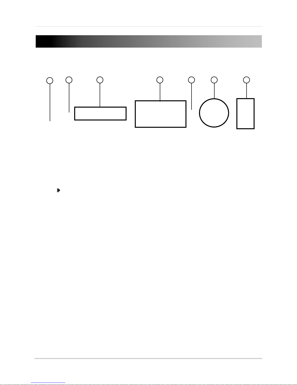
FRONT PANEL
1
6
2
3 4 5 7
1. Power: Press to power the system ON/OFF.
2. IR Sensor:
3. LED Indicators: Shows s
4. Channel/Numbers/Playback:
models) to view the selected channel in full-screen; press buttons 1~0 to input passwords
and user IDs; during playback, press the following:
• 6/
: Increase reverse playback speed 1X, 2X, 4X
• 7/
: Press to freeze playback to one frame, then press again to advance frame-by-frame
: Press to start playback
• 8/
: Press to slow playback speed by 1/2, 1/4, 1/8
• 9/
• 0/
: Press to increase forward playback speed 1X, 2X, 4X
IR receiver for the remote control.
tatus of HDD, recording, alarm, network, and power.
Press buttons 1~4 (4-channel models) or 1~8 (8-channel
5. MENU/EXIT: Pr
6. Navigation/OK: Pres
• OK/PTZ:
buttons to control the connected PTZ camera (not included)
S: Press to move cursor up; in PTZ mode, press to pan camera up
•
•
T: Press to move cursor down; in PTZ mode, press to pan camera down
W: Press to move cursor left; in PTZ mode, press to pan camera left
•
X: Press to move cursor right; in PTZ mode, press to pan camera right
•
7. USB: Connect
connect a USB mouse to the bottom port.
ess to open/close the main menu.
s the Navigation buttons to perform the following:
In menus, press to confirm selections; in PTZ mode, press to change the navigation
a USB flash drive to the top port for data backup and firmware upgrades;
11
2
Page 16
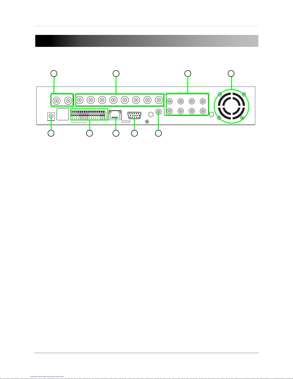
REAR PANEL
3
6
1 2
4
5
7
8
9
VIDEO OUT
12123456778
1234567
DC +19V
IN
8
ALM IN
VIDEO IN
VGARJ45
AUDIO OUT
AUDIO IN
5
3
1
5
4
2
1. Video Out: Connect up to two external BNC monitors (not included).
2. Video In: Connect
3. Audio In: RC
4. Exhaust fan: Do not bl
up to eight BNC cameras.
A input for up to eight audio enabled cameras (not included).
ock to allow for proper ventilation.
5. DC: Port for 19V DC 3.42 A power adapter (included).
6. Alarm block: Connection bl
7. LAN/RJ45: Netw
orking port for a 10/100 Base-T RJ-45 network cable (included).
8. VGA Output: Connect an
9. Audio Ou
t: RCA output for external speakers or other audio devices (not included).
ock for external alarm/motion devices (not included).
external VGA monitor (not included).
8
3
Page 17
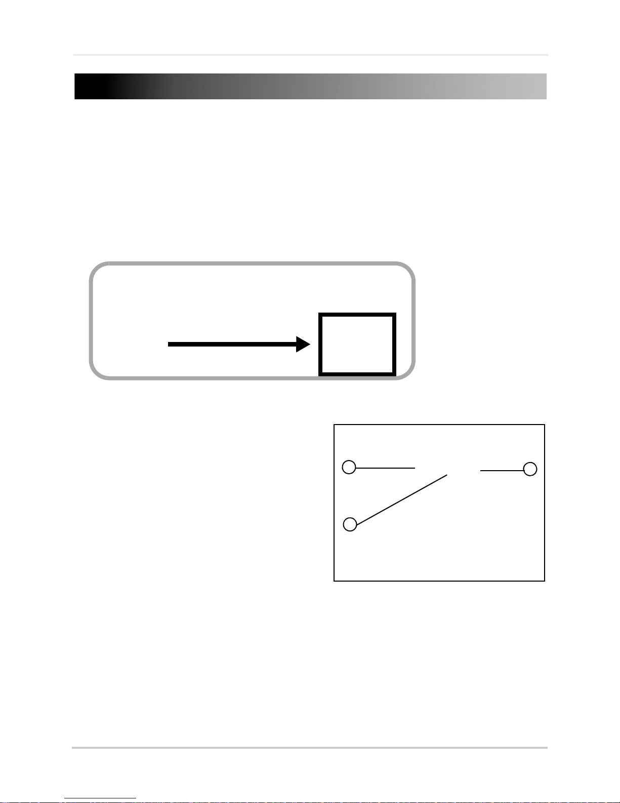
MOUSE CONTROL
Figure 1.0 Connect a USB mouse to the bottom USB port on the front panel
1
2
3
Figure 1.1 Mouse button operation
The mouse is the primary input device for navigating system menus.
NOTE: Unless otherwise noted, all system functions described in this manual are achieved through
mouse input.
To use a mouse with the system:
1. Connect a USB mouse to th
NOTE: Only the
connect a USB flash drive to the bottom USB port on the rear panel.
top
USB port on the front panel is designed for data backup to a USB flash drive. Do not
e USB MOUSE port on front panel of the system.
2. Use the mouse buttons to perform the following:
• Left-Button: Click t
o select a menu option;
d u r i n g l i v e v i e w i n g i n s p lit-screen, double-click
on a channel to view the selected channel in
full-screen.; double-click the channel again to
return to split-screen view
• Right-Button: Click to open the Sub-Menu (see
“Using the Sub-Menu” on page 8.)
3. Scroll-Wheel: No
4
function.
Page 18
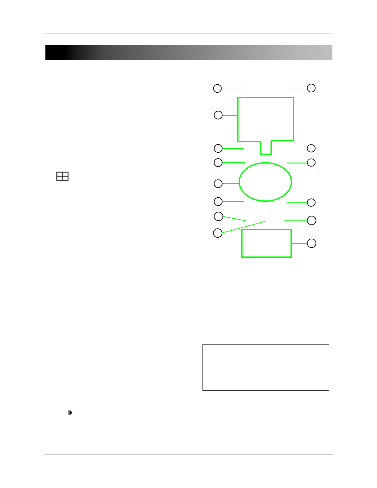
REMOTE CONTROL
Figure 2.0 Remote Control
6
1
2
3
4
5
6
7
8
9
9
10
12
11
12
*Audio capable cameras (not included) are required for audio
record ing and listen-in aud io functionality.
TIP: When using the remote control to
enter password and camera titles,
select the field using the navigation
buttons, press ENTER, and then press
the number buttons.
The remote control is the secondary input device
for navigating the system’s interface.
To use the remote control:
1. STANDBY: Press to turn standby mode ON/OFF.
2.
LOGIN/LOCK: If "Security" has been enabled in the
Setup menu, press to open the user password login
screen.
3.
Number/Channel buttons: While in menus,
press buttons 0~9 to enter values; during live
viewing, press to view channels in full-screen.
4. : Press to switch between quad and
split-screen displays.
5. MENU: Open
6.
PTZ: Press to open the PTZ control window.
7.
EXIT: Close menu windows.
Navigation/OK:
8.
• S/CH+: Move cursor in menus up; Channel Up.
• X/FWD: Move cursor in menus right; during
playback, increase forward playback speed (5X, 15X,
60X).
• W/
playback, increase reverse playback speed (5X, 15X,
60X)
• T/
• OK: In menus, press to confirm selections; during
playback and preview, press to view system
information
s the main menu.
REW: Move cursor in menus left; during
CH-: Move cursor in menus down; Channel down.
9. +/ - : In menus, press to adjust values.
10. RECORD: Pres
11. STOP: Pr
12. EXTRA: Open
13.
ess to stop manual recording.
the system menu.
Playback controls:
• : Increase reverse playback speed 1X, 2X, 4X
• : Press to start playback
: Press to increase forward playback speed 1X, 2X, 4X
•
: Press to slow playback speed by 1/2, 1/4, 1/8
•
Press to freeze playback to one frame, then p
• :
14. AUDIO: Press to open the Audio recording menu.*
15. MUTE: Pre
ss to mute listen-in audio on the system.*
s to start manual recording.
ress again to advance frame-by-frame
5
Page 19
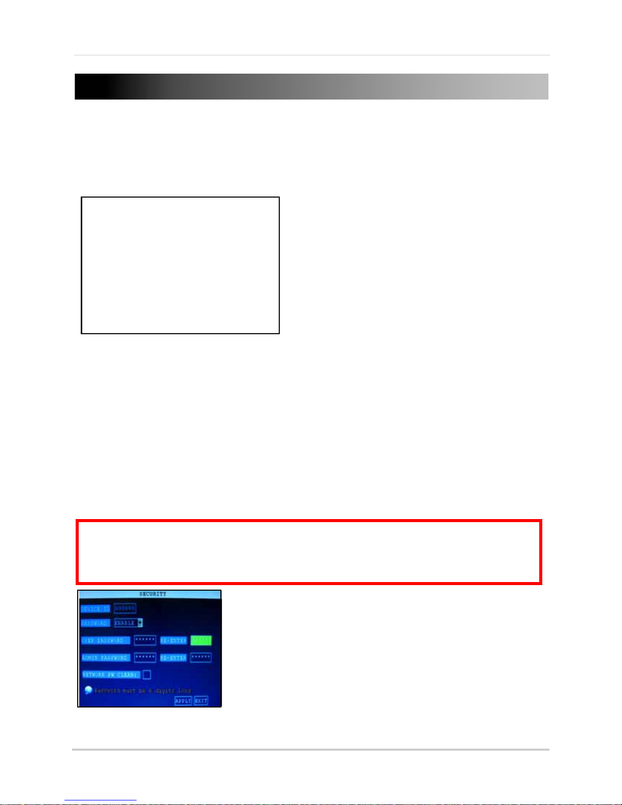
STARTING THE SYSTEM
Figure 3.0 Initial startup screens
ATTENTION: By default, passwords are disabled on the system. You do not need to enter a
password when accessing any system menus. However, for security purposes, it is highly
recommended to enable passwords on the system using the Password Menu.
For details, see
“Managing Passwords” on page 13.
Figure 3.1 Password menu
To power the system ON/OFF:
• Connect the power cable to the DC 19V port on the rear panel.
At startup, the system performs a basic system check and runs an initial loading sequence.* After a few
moments, the system loads a live display view.
Standby Mode
The system can also be put into Standby Mode. Power will remain to the system but will not be
recording.
To start/stop Standby mode:
1. Press and hold the POWER butt
closes. The system enters standby mode.
2. Press and hold the POWER button on the fr
beeps. The system will begin powering up.
on on the fr
ont panel or remote control until the prompt
ont panel or remote control until the system
Password
6
Page 20
USING THE ONSCREEN DISPLAY
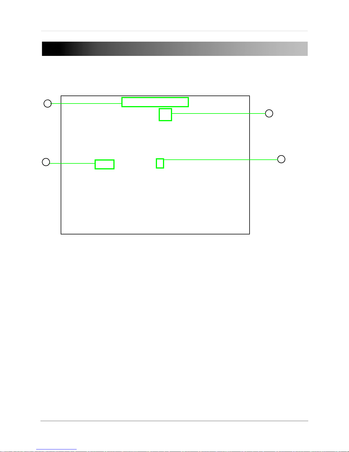
Figure 4.0 Live viewing with onscreen display
3
4
1
2
Use the system’s graphical onscreen display to navigate menus and configure options and
settings.
1. Date & Time: Displa
ys the date and time on the system; OW—Overwrite will also appear in
this display if the function is enabled.
2. Channel Title: Displays the customizable name for the channel.
3. Record Status: Displays the current recording status of the system: R=recording,
C=continuous (normal recording); M=motion recording; A=alarm recording.
4. Channel number: Displays
channel number.
7
Page 21
Using the Onscreen Display
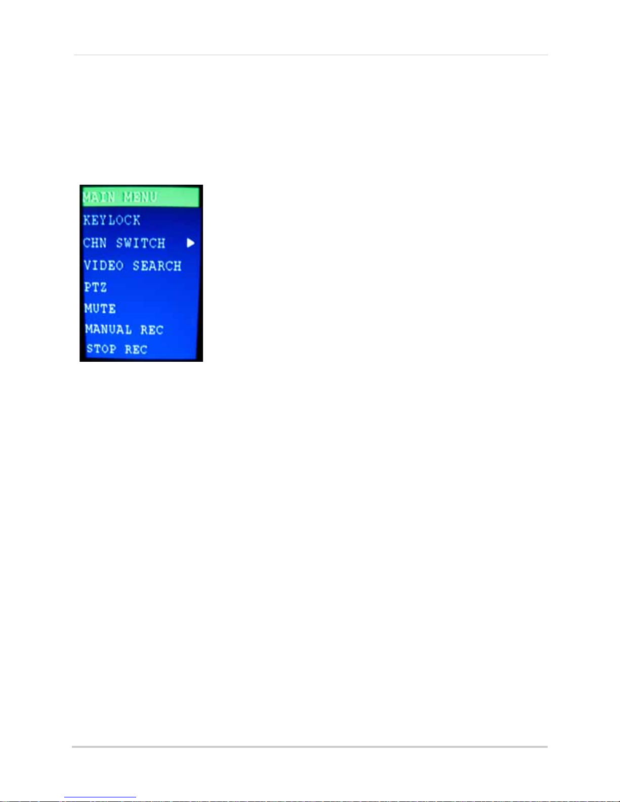
Figure 4.1 Sub-Menu
Using the Sub-Menu
Mouse Only
When using the mouse, use the Sub-Menu to access several system options, including the Main
Menu and PTZ control.
To open the Sub-Menu:
1. Right-click anywhere onscreen. The Sub-Menu opens.
2. Select one of the following options:
• MAIN MENU:
Opens the main
system menu
• KEYLOCK: Locks buttons on the front panel
• CHN SWITCH: Select type of split-screen display
• VIDEO SEARCH: Open the Search Menu to view recorded video
• PTZ: Opens the PTZ control menu*
• MUTE: Mute listen-in audio on the system**
• MANUAL REC: Start manual recording
• STOP REC: Stop manual recording
3. To close the Sub-Menu, click anywhere onscreen.
*PTZ cameras are not included with the system.
**Audio capable cameras (not included) are required for audio recording.
8
Page 22
Using the Onscreen Display
Figure 4.2 Virtual Keyboard—numerals
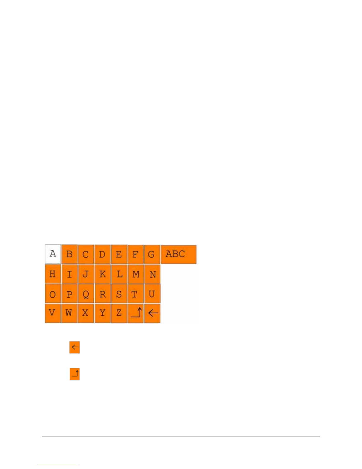
Figure 4.3 Virtual Keyboard—alphabet
Using the Virtual Keyboard
Mouse Only
When using the mouse, you can input certain values using the onscreen virtual keyboard.
You will need to use the Virtual Keyboard when entering
To use the Virtual Keyboard:
your User ID and Password.
1. Click on an option or field, such as the User ID
assword fields. The Virtual Keyboard
and P
opens.
2. Click 0~9 to
3. Click 123 to
enter the desired digit.
switch between numerals, upper and lowercase letters, and other characters
(only for certain options).
4. Click to Backspace/Delete.
NOTE: The buttons will turn from orange to white when you select the button with the mouse cursor.
5. Click to enter/confirm and close the Virtual Keyboard.
9
Page 23
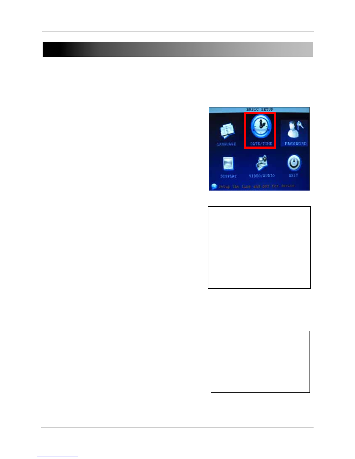
SETTING THE DATE AND TIME
Figure 5.0 Click DATE/TIME from the Setup Menu
Figure 5.1 Configure date & time options
Figure 5.2 Configure DST settings
It is highly recommended to immediately set the date and time when first setting up your system.
To set the date and time:
1. Right-click anywhere on the screen to open the
Sub-Menu and sel
opens.
2. From the Main Menu, click
opens.
3. Click DATE/TIME and configure the following options:
• DATE: En
• DATE FORMAT: Select DD/MM/YYYY, MM/DD/YYYY,
or YYYY/MM/DD
• TIME: Enter the time
• TIME FORMAT: Use the drop-down menu and select
12HOURS or 24HOURS
• DST: Use the drop-down menu to select ON/OFF to
enable/disable Daylight Savings Time
4. Click MODIFY
confirmation window.
5. Click APPLY. The new dat
ter the day, month, and year
DATE AND TIME. Click CLOSE in the
ect MAIN MENU. The Main Menu
BASIC. The Setup menu
e and time are saved.
Daylight Savings Time
To set daylight savings time:
1. Under DST, select ON. DST options appear
2. Under DST MODE select one of the following:
• CUSTOM: Set cus
(go to step 4)
• DEFAULT: The Default setting will apply DST from the
second Sunday of March to the second Sunday in
November (go to step 3)
3. If using the DEFAULT, click APPLY.
4. If setting a CUSTOM DST, use the drop-down menus to
sele
ct a week and month for the start and end times.
5. Click APPLY. Click CLOS
6. Click EXIT in each
.
tomized start and end times for DST
E in the confirmation window.
menu until all windows are closed.
10
Page 24
RECORDING
R.C
R.M
R.A
ATTENTION: Audio capable cameras (not included) or self-powered microphones are
required in order to record audio on the system. The SG7550A (not included) is an
audio-capable BNC camera. Visit www.lorexcctv.com for more details.
Audio capable
camera
Video
(BNC)
Audio
(RCA)
Figure 6.0 Connecting an audio capable camera
*8-channel model shown
By default, the system is set to immediately record video from connected cameras in Continuous
Recording Mode.
• Recording—Continuous: Normal, continuous r
ecording
You can set the system to stop recording once the hard drive is full, or to continually record by
overwriting previously reco
rded data. For more details, see “HDD” on page 18.
Event Recording
The system also includes two modes of event recording:
• Record
ing—Motion: The system records when motion is detected by the camera
• Recording—Alarm: The system records when an alarm or sensor is triggered
For details on Motion Detection see “MOTION DETECTION” on page 23. For details on Alarm
recording, see “ALARM” on page 21.
Recording Audio
The system can also record audio for each channel (
respective model
).
4 or 8 audio channels depending on your
To enable audio recording:
1. Connect the BNC video cable from the camera
to one of the
BNC ports on the rear panel of the
system. For example, connect the camera to
BNC port 1.
Connect the RCA audio cable from the camera
2.
to the
corresponding audio channel. Following
the example in step 1, you would connect the
cable to audio port 1.
3. Open the Main Menu and click REC
4. Under AUDIO, select ENABLE.
5. Click APPLY.
6. Click EXIT in all
closed.
ORD.
menus until all windows are
11
Page 25
PLAYBACK
|
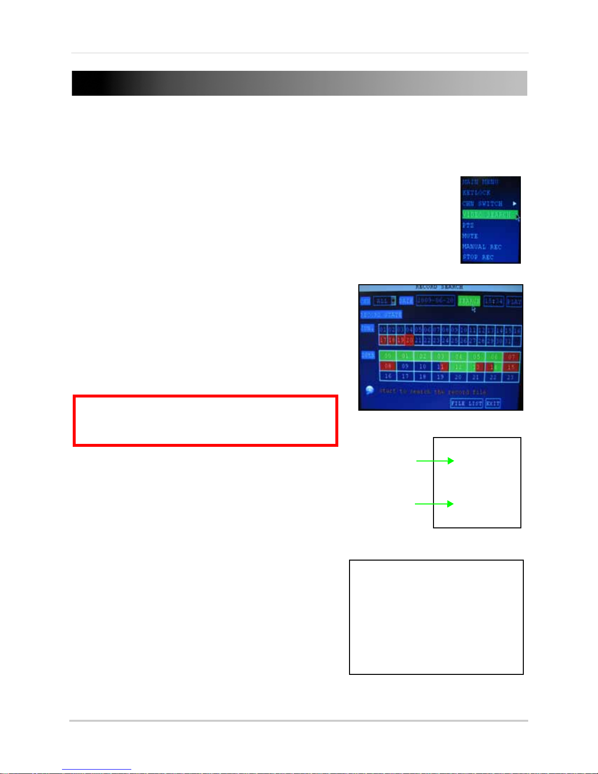
Figure 7.0 Select VIDEO SEARCH
Figure 7.1 Search menu
Figure 7.3 Playback with onscreen controls (mouse)
Month Grid
Hour Grid
Figure 7.2 Setup menu
ATTENTION: Only single channel full-screen playback is
available on 8-channel models; 4-channel models have
full-screen and quad-screen playback.
View recorded video on the system through the Search Menu.
To begin playback:
1. Right-click anywhere onscreen and select VIDEO
SEARCH. The Search Menu opens.
NOTE: When you first open the Search Menu, it displays the
current month and date.
2. Click PLAY to playback the last minute of recorded
video (Quick Search).
or
e
3. Under CHN select a sp
4. Under DATE, enter a date using the Virtual Ke
(mouse only).
5. Click SEARCH. Rec
appear in red (alarm events—includes both alarm
and motion events) and green (normal recording).
6. Click a date in the Month Grid t
7. Click a time bl
ock in the Hour Grid to view the video.
Playback begins.
cific channel or select ALL.
yboard
orded events on the system
o search for video files.
8. Move the mouse slightly to display the onscreen
ont
rols. You can also use the playback
playback c
control buttons on the remote control or front panel
of the system.
For more information on using the Search Menu, see
“SEARCH” on page 15.
Onscreen Playback Controls
To use the onscreen playback controls:
1. Click the VCR-like controls to play, pause, fast
forwar
d, rewind, and slow down playback.
2. Drag the slider to adjust the volume (audio capable
ca
mera required, not included). Select the box to
mute the audio.
3. Click X to
quit playback and return to the Search
menu.
12
Page 26
MANAGING PASSWORDS
ATTENTION: By default, passwords are disabled on the system. You will not need a password to log in
or access menus. You will not need a password to access your system using the browser-based
remote software.
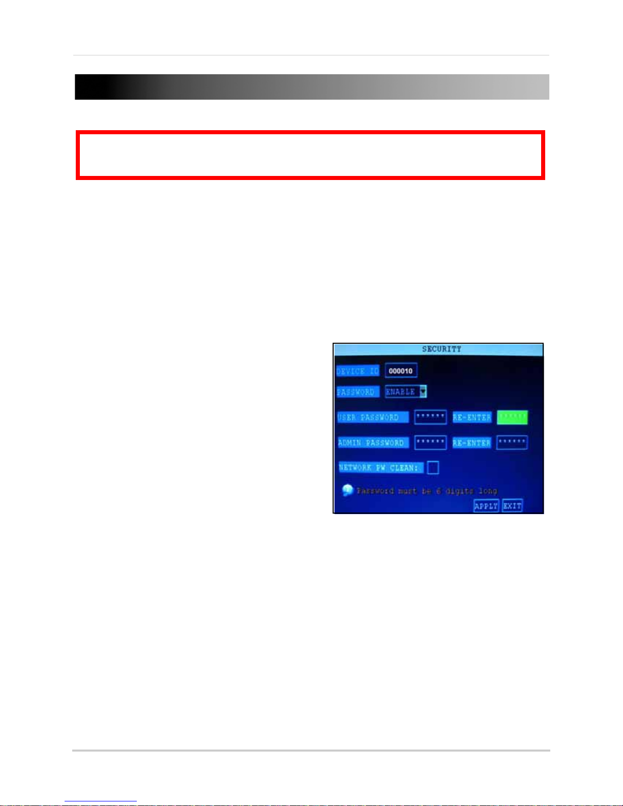
Figure 8.0 Password menu
When you first startup your system, you are technically logged in as the ADMIN under Device ID
000000. The system employs two user authorities connected to a
follows:
• ADMIN—administrator: Has full control of the system, and can change both administrator and user
passwords and enable/disable password checking
• USER—normal user: only has access to live viewing, search, playback, and other limited authorities
For security reasons, it is highly recommended to enable passwords on your system. If you enable
and
passwords, you must select a 6-digit USER password
a 6-digit ADMIN password.
Changing Your Device ID and Password
You can change the Device ID and password of the
ADMIN and the USER from the Password/Security
menu.
To open the Password/security menu:
1. Right-click anywhere onscreen to open the
Sub-Menu and sel
2. Click BASIC. The Basic
3. Click PASSWORD. The Pa
menu opens.
To change your Device ID and Password:
ect MAIN MENU.
Setup Menu opens.
ssword/Security
Device ID
. The authorities are as
1. Click the field beside DEVICE ID
6-digit numerical Device ID using the Virtual
Keyboard (mouse only). For example, change
the ID to
2. Under PASSWORD, sele
3. Click the field beside USER PAS
Virtual Keyboard (mouse only). Re-enter the password in the corresponding field.
4. Click the field beside ADMIN PASSWORD to ent
Virtual Keyboard (mouse only). Re-enter the password in the corresponding field.
NOTE: The USER and ADMIN passwords must not be the same.
5. Click APPLY to save your changes. Click CLOSE in the confirmation window.
6. Click EXIT in each
Use your new password to log in to the system and access system menus. You can also use the
and ADMIN passwords to access your system using the browser-based remote software.
USER
If desired, you can create a
For more details, see “Setting a Network Password” on page 37.
000010
.
ct ENABLE.
menu until all windows are closed.
Network password
and enter a
SWORD to enter a 6-digit numerical password using the
er a 6-digit numerical password using the
from the Settings menu in the Remote Software.
13
Page 27

Using the Main Menu
Figure 9.0 Main Menu
3
1 2
4 5 6
7
USING THE MAIN MENU
To open the Main Menu:
• Right-click anywhere onscreen to open the Sub-Menu and select MAIN MENU (mouse only),
or pr
ess the MENU/EXIT button on the remote control or front panel of the system.
NOTE: If passwords are enabled on the system, you need to select your Device ID and enter the 6-digit
numerical password to open the Main Menu.
1. SEARCH: Search for recorded video and log files on the system.
2. RECORD:
enable/disable audio recording.*
3. HDD: Display hard
4. BASIC: Open the
Device IDs and passwords, and configure audio and video settings.
5. ADVANCE: Opens the A
alarm, PTZ, mobile, and network settings.
6. EXIT: Closes the Main
7. Displays information about the contents of the select
*Audio capable cameras (not included) are required for audio recording on the system.
Configure recording parameters (quality, resolution), set record modes, and
drive status and format the internal hard drive of the system.
Basic Setup Menu, which lets you set the system language, date and time,
dvanced Setup Menu, which lets you view system info, configure
Menu.
ed Main Menu icon.
14
Page 28

SEARCH
Figure 10.0 Search menu
Figure 10.1 Month and Hour grids
Month Grid
Hour Grid
Figure 10.2 File list menu
Search and playback recorded
video on your system.
remote control or front panel to control
playback.
NOTE:
“Playback” on page 12.
For details on Playback, see
File List
Use the File List sub-menu to see a detailed
list of all the recorded video on your system.
To open the File List:
NOTE: When you first open the Search menu, it
will display the current month and date.
To perform a Quick Search:
1. Open the Search menu and click PLAY. The
last
minute of recorded playback begins.
To perform a Date & Time search:
1. Under CHN, select indi
vidual channels or
select ALL.
2. Under DATE, click the field and enter the
desi
red date using the Virtual Keyboard
and then click SEARCH. The system
searches for data.
3. Under RECORD STATE, the system shows
rec
orded events in a Month Grid and a
Time Grid. The selected day of the month
will be outlined in red. Green=normal
recording; Red=alarm recording (includes
both alarm and motion events).
4. Click a date in the month grid to view
orded video files for that selected date
rec
in the hour grid.
1. From the Search Menu, click SEARCH to
ch the system for recorded video.
sear
2. Click FILE LIST at the bott
om of the menu.
The File List menu opens.
To use the File List:
1. Under TYPE, select NORMAL to
view only
normal recordings, ALARM, to view alarm
recordings (includes alarm and motion
detection), or ALL to view all video on the
your system.
2. Use the buttons on the side panel to
navigate
the file list:
• FIRST: Jump to the first page of the list
• PRE: Turn to the previous page
• NEXT: T
• LAST: Jump to the last page of the list
• ALL: Select all files
urn to the next page
5. During playback, use the onscreen
ntrols or the playback buttons on the
co
• OTHER: Cl
• BACKUP: Aft
begin copying the data to a USB flash drive
(not included); For details, see “Backup”
on page 16.
ear all files
er selecting a file(s), click to
3. Click any file to begin playback.
15
Page 29

Using the Main Menu
Figure 10.3 Select files and click BACKUP
3
Figure 11.0 Record menu
Backup
Use the File List sub-menu to find recorded
video on your system and copy it to a USB flash
drive (not included).
NOTE: The system is compatible with most
major brands of USB flash drives, with
capacities from 256 MB to 4 GB.
To backup recorded data:
1. Connect a blank USB flash drive to the top
US
B port on the front panel of the system.
2. Open the Search menu and search for
rec
orded data on the system.
3. Click FILE LIST.
4. Select the files you want to backup and
click
the "BAK" box next to the file name
(see figure 0.0). Select multiple files if
desired. Click ALL to select all files; click
OTHER to deselect all files.
NOTE: The size of each file is shown in the File
List menu. Use this to help you find a USB flash
drive large enough to hold all the files you wish
to backup.
5. Click BACKUP from the side-panel to
immediately begin copying the files to the
USB flash drive.
NOTE: Backup progress appears in the status
window.
during backup.
DO NOT
6. If backup is successful, click CLOSE in the
confirmation window and then remove the
USB flash drive.
NOTE: If there is not enough space on the USB
flash drive, the system will display the following:
"Space is not enough."
remove the USB flash drive
RECORD
Configure record parameters,
enable/disable audio.
NOTE: Audio capable cameras (not included) are
required for audio recording.
To configure recording options:
1. Under CHANNEL, use the drop-down
menus and select ON/
disable recording from the selected
channel.
2. Under QUALITY, select HIGHEST, HIG
NORMAL.
3. Under AUDIO, select ENABLE or DISA
If audio recording is enabled, the system
will record audio from connected audio
capable cameras (not included).
4. Under REC. MODE, select POWER UP or
TIME
R RECORD. If you select POWER UP,
the system will record continuously
(Normal Recording) when the system is
powered on. If you select TIMER RECORD,
you have to set a recording schedule on
the system. See “Setting a Recording
Schedule” on page 17.
OFF to enable/
H, or
BLE.
Backup File Data
The system will create a folder on the USB
flash drive named
saved as .264 files.
16
RecordFile
. The files are
Page 30

Using the Main Menu
Figure 11.1 Recording Schedule
Figure 11.2 Customized recording schedule
5. Under REC. SIZE, select 15MIN, 30MIN,
45MIN, or 60MIN.
NOTE: R ecord Size se ts the file size for recorded
video files on the system. Instead of recording
data as one large file, the system will divide the
data into blocks of 15, 30, 45, or 60 minutes. This
makes the recorded data easier to search.
6. Click APPLY. Click CLOSE in the
confirmation window.
7. Click EXIT in ev
ery menu until all windows
are closed.
Setting a Recording Schedule
By default, the system is set to record
continuously. You can program the system to
record according to a customized recording
schedule.
The Schedule Grid shows the days of the week
and hours 0~23.
(Red), General (Normal) Recording (Green), or
No Recording (Blue) to each time block of each
day.
To set a recording schedule:
You can set Alarm Recording
7. Click SAVE.
8. Click EXIT in each
menu until all
windows
are closed.
Example
You want your system to record continuously
on all channels from 9 AM to 5 PM Monday to
Friday. You also want Alarm/Motion recording
from 5 PM to 9 AM. You do not want the system
to record Saturday or Sunday.
NOTE: By default, the system is set to record
continuously 24 hours a day, 7 days a week.
To set the recording schedule:
1. Open the Schedule menu.
2. Under CHANNEL, select ALL.
3. Click the bl
ue NO R
the grid. A checkmark will appear in the
block.
4. Under SUN, click blocks 00~23. The
ocks will turn blue.
bl
5. Under FROM, select SUN. Under T
SAT, and then click COPY.
6. Click the red ALARM block bel
7. Under MON, click blocks 00~8 and
18~23. The blocks will turn red.
8. Under FROM, select MON. Under TO
TUE, and then click COPY. Repeat for
Wednesday, Thursday, and Friday. Your
completed schedule should the same as
the schedule in figure 11.2.
ECORD block below
O select
ow the grid.
blocks
select
1. Open the Main Menu and click REC
2. Under REC. MODE, select TIMER RECORD.
3. Click SCHEDULE. The Schedule
opens.
4. Under CHANNEL, select specific channels
or sel
ect ALL.
5. Below the grid, click either ALARM (red)
GENERAL (Green), or NO RECORD (Blue)
and then click a time block on the desired
day.
6. Use the FROM/TO drop-do
copy the schedule of one day to another.
For example, if you want your schedule for
Monday to be the same on Wednesday:
under FROM select MON, under TO select
WED, and then click COPY.
ORD.
menu
wn menus to
,
9. Click SAVE. Click CL
OSE in
the
confirmation window.
10. Click EXIT in all me
nus until all windows
are closed.
17
Page 31

Using the Main Menu
Figure 11.3 Mask Field menu
Figure 11.4 Mask Field menu
Figure 12.0 HDD menu
Mask Field Setup
The Mask Field lets you block a specific portion
of a channel you do not want recorded or
shown on the display screen. This can be
useful if you need to conceal a sensitive area
being captured by the installed camera.
To use the mask field:
1. From the Record menu, click MASK
SETUP. The Mask Field menu opens.
2. Choose a channel you wish to apply the
Mask Fiel
(8-channel models only). Select ON from
the SWITCH drop-down menu.
3. Click SETUP. The Mask
and the select channel is shown in
full-screen.
4. Using the mouse, click and drag the
curs
A single click will produce a small black
square.
d. Click NEXT PAGE if necessary
Menu disappears
or over the area you want to conceal.
FIELD
HDD
Displays essential information
about the system’s internal hard
drive, and lets you format the internal HDD and
external USB flash drive (not included).
The HDD menu displays the following:
• HDD STATUS: The syst
"OK" for normal operation
• SIZE: The size (in gigabytes) of the internal
hard disk drive
• The size of your system’s internal hard
drive will vary by model
• FREE SPACE: The space (in gigabytes)
remaining on the system’s internal HDD
• AVAILABLE TIME: The recording time (in
hours) remaining on the HDD based on
your current record settings
• OVERWRITE: Select ENABLE or DISABLE.
If Overwrite is
record over the oldest video data once the
HDD is full. If Overwrite is
system will stop recording once the HDD
is full and the "FULL" LED on the front
panel of the system will light up
enabled
em will display
, the system will
disabled
, the
5. Right-click anywhere on the screen to
re
turn to the Mask Field menu.
6. Click APPLY. Click CLOSE in the
c
onfirmation window.
7. Click EXIT in all menus until all
are closed.
18
windows
Page 32

Using the Main Menu
ATTENTION: Formatting the HDD will
erases
all
video data. This step
cannot
be
undone.
Figure 12.1 Formatting warning
Figure 12.2 Formatting warning
Formatting the Hard Drive
To format the internal HDD:
1. Open the Main Menu and click HDD.
2. From the HDD menu, click HDD FORMAT.
From the Warning prompt, click SURE. The
3.
tem will begin formatting the hard
sys
drive. This may take several moments
depending on the size of the HDD.
4. Once formatting is complete, click CLOSE
in the confirmation window
will automatically restart and load to the
default live viewing display.
5. Open the Main Menu and click HDD to
check the
NOTE: You will notice that the size of the HDD
and the free space are not the same. The system
uses a portion of the disk space for the operating
system and initialization. This is common in all
security DVRs as well as common PC hard
drives.
status of the hard drive.
. The system
Formatting the USB Flash Drive
Use a USB flash drive to backup recorded video
and upgrade the system’s firmware. You
should always format the USB flash drive you
intend to use with the system.
NOTE: Not formatting the USB flash drive may
result in improper functionality.
To format the USB flash drive:
1. Connect a USB flash drive to the top USB
port on the fr
2. Open the Main Menu and click HDD.
3. Click USB FORMAT.
4. From the Warning prompt, click SURE. The
tem will begin formatting the USB flash
sys
drive. This may take several moments
depending on the size of the USB flash
drive.
DO NOT
while formatting is taking place.
5. When formatting is complete, click CLOSE
the confirmation window. It is now safe
in
to remove the USB flash drive from the
system.
ont panel of the system.
remove the USB flash drive
19
Page 33

Using the Main Menu
Figure 13.0 Basic Setup menu
Figure 13.1 Language menu
BASIC
Set the system language, date and
time, passwords, and configure
audio and display options.
The Basic Setup menu contains the following
sub-menus: Language, Date/Time, Password,
Display, and Video/Audio.
LANGUAGE
DISPLAY
Use the Display Setup menu to customize
channel titles, show/hide the date and time in
live viewing and playback, and enable/disable
covert channels.
To customize Display settings:
1. Configure the following options:
• NAME: Click any of the fields and enter a
ne
w title for the selected channel using
the Virtual Keyboard (mouse only)
• POSITION: Reposition the channel title;
select TOPLEFT, BOTTOMLEFT,
TOPRIGHT, BOTTOMRIGHT, or OFF. If
OFF
, the title will not be displayed for the
selected channel
• COLOR: Adjust CHROMTICITY,
LUMINOSITY, CONTRAST, and
SATURATION for the selected channel
• PREVIEW TIME: Select ON/OFF to show/
hide the date and time during live viewing
• RECORD TIME: Select ON/OFF to show/
hide the date and time during playback
To change the system language:
1. From the drop-down menu select
ENGLISH, or Chin
2. Click APPLY. Click CLOSE in the
c
onfirmation window.
3. Click EXIT to close the
ese.
menu.
DATE/TIME
For details on setting the date and time, see
“Setting the Date and Time” on page 10.
PASSWORD
For details on setting Device IDs and
passwords, see “Managing Passwords” on
page 13.
2. Click NEXT PAGE to
for the remaining channels (8-channel
models only).
3. Click APPLY to
CLOSE in the confirmation window.
change the settings
save your settings. Click
Covert Channels
Covert channels can be very useful if your
display monitor is in public view. A covert
channel will appear black on the display to give
the impression that no cameras are connected
and the system is not recording.
To enable/disable covert channels:
1. Choose a channel you wish to conceal. For
ample, channel 3. Under COVERT, select
ex
OFF.
2. Click APPLY. Channel 3 wi
Click CLOSE in the confirmation window.
3. Click EXIT in all
are closed.
menus until al windows
ll turn black.
20
Page 34

Using the Main Menu
Figure 13.2 Video/Audio menu
Figure 14.0 Video/Audio menu
Figure 15.0 Video/Audio menu
VIDEO/AUDIO
Use the Video/Audio menu to set the resolution
and camera system on the system.
To configure video options:
1. Under VGA RESOLUTION, select 800x
or 1024x768.
2. Under CAMERA SYSTEM, select NTSC or
PAL.
3. Click APPLY. Click CLOS
confirmation window.
4. Click EXIT in all
are closed.
To configure audio options:
1. From the Video/Audio menu, click
VOLU
ME SETUP.
view appears.
2. Click any channel and adjust the slider to
increase/decr
audio.
3. Click X to r
4. Click APPLY. Click CLOS
confirmation window.
5. Click EXIT in all
are closed.
menus until all windows
A split-screen display
ease the volume for listen-in
eturn to the Video/Audio menu.
menus until all windows
E in the
E in the
600
ADVANCE
Use the Advanced Setup menu to
configure alarm settings, motion
detection, mobile surveillance, PTZ
settings and network settings.
The Advanced Setup menu contains the
following sub-menus: Alar
Mobile, System, PTZ, and Network.
ALARM
Use the Alarm menu to configure alarm and
email settings.
NOTE: External alarm devices must be
connected to the alarm block on the rear panel
of the system in order to use the I/O (input/
output) alarms of the system.
m, Info, MD,
To configure alarm settings:
1. Under I/O CHANNEL, select NO (Normal
Open), NC (Normal Closed),
NEXT PAGE to view additional channels
(8-channel models only).
2. Apply loss alarms to the following:
or OFF. Click
21
Page 35

Using the Main Menu
Figure 15.1 Email Setup menu
Figure 16.0 System Information
• HDD LOSS: the alarm will sound if the
internal HDD is damaged
• HDD SPACE: the alarm will sound when
the HDD is full (overwrite must be
disabled)
• VIDEO LOSS: the alarm will sound when
a camera is disconnected
3. Under ALARM MANAGE, configure the
following:
• OUTPUT: Set the output time (in seconds)
on
the spot monitor from 0s, 10s, 20s, 40s,
or 60s
• BUZZER: Set the time (in seconds) for the
buzzer when an alarm is triggered—0s,
10s, 20s, 40s, or 60s
NOTE: Set the buzzer to 0s if you want to disable
the alarm during motion detection
• POST REC: Set the time (in seconds) for
the system to record after a triggered
alarm—0s, 10s, 20s, 40s, or 60s
4. Click APPLY. Click CLOSE in the
onfirmation window.
c
3. Under SMTP PORT, enter the SMTP port of
your email server.
4. Under SMTP, enter the SMTP addr
ess of
your email server. For example,
smtp.connection.ca
5. Under SEND EMAIL, enter the sender
email addres
s.
6. Under SEND PW, enter the password of
you
r email server.
7. Under RECV EMAIL, enter the email
addres
s that will receive the email
notification.
8. Click APPLY. Click CLOS
E in the
confirmation window.
9. Click EXIT in all
menus until all windows
are closed.
INFO
View system information, including the IP
address, MAC address, and HDD capacity of
the system.
ALARM SETUP
Click ALARM SETUP and select ON/OFF to
apply an external alarm trigger to a channel.
EMAIL SETUP
The system can send an email notification with
a JPEG snapshot for triggered events on the
system.
To setup email notification:
To view system information:
1. From the Advanced Setup menu, click
INFO.
or
1. From Live viewing, press the OK button on
e front panel of the system.
th
2. View the system’s IP address, MAC
addres
s, Disk Capacity, Video Signal Type,
Net Client Port, and Web Server Port. Click
OK to close the menu.
1. Under EMAIL, select ON.
2. Under SSL, select OFF.
NOTE: SSL deals with encryption. Only advanced
users should enable this option.
22
Page 36

Using the Main Menu
Figure 17.0 System Information
Figure 17.1 Motion Grid
Figure 18.0 Mobile menu
MOTION DETECTION
Configure motion detection for each channel.
To configure motion detection:
1. Under STATUS, select ON to en
detection for the desired channel. Click
NEXT PAGE for additional channels
(8-channel models only).
2. Under SENSITIVITY, select 1, 2, 3, or 4. The
higher the number, the more sensitiv
motion detection.
3. Under MD SETUP, click SETUP. The re
motion grid appears over the selected
channel in full screen.
4. Click the blocks in the grid to enable/
disable
detection
disabled
NOTE: You can click and drag the mouse cursor
when selecting/deselecting the blocks.
motion detection. Red=motion
enabled
; Clear=motion detection
.
able motion
e the
d
MOBILE
Send alerts to your Windows Mobile enabled
touch-screen smart phone (Windows Mobile
6.0 or greater is required).
NOTE: Currently, mobile viewing is supported by
only
Windows Mobile
To configure mobile notification settings:
1. Under MOBILE NETWORK, select 3G,
2.75G, or 2.5
NOTE: Contact your cellular provider if you are
unsure about the network of your cellular
phone.
2. Under MOBILE PORT, enter your mobile
port number (by default, 100).
3. Click APPLY. Click CLOSE in
confirmation window.
4. Click EXIT in all me
are closed.
For complete details on setting up mobile
viewing on
your Windows Mobile phone, please
see “Appendix L: Mobile Phone Instant
Viewing” on page 64.
.
G.
the
nus until all windows
5. Right-click anywhere on the screen to
return to the Motion Detection menu.
6. Click APPLY. Click CLOS
confirmation window.
7. Click EXIT in all
menus until all windows
are closed.
NOTE: You can disable the buzzer in the Alarm
menu. See “ALARM” on page 21.
E in the
23
Page 37

Using the Main Menu
Figure 19.0 System menu
Figure 19.1 Firmware upgrade progress
SYSTEM
Use the System menu to update system
firmware and set an automatic system reset
schedule.
To enable auto-reset:
1. Under AUTO RESET, select ON. The
Settings opti
2. Under SETTINGS, select EVERY DAY,
EVERY WEEK
drop-down menu appears.
3. Select the date for auto-reset from the
drop-do
4. Enter the time for auto-reset using the
Virtual Ke
5. Click APPLY. Click CLOSE in the
c
onfirmation window
on appears.
, or EVERY MONTH. The date
wn menu.
yboard (mouse only).
Upgrading Firmware
Your system will periodically need firmware
updates to ensure optimal performance. Visit
www.lorexcctv.com to check if upgrades are
available for your system.
To upgrade firmware:
1. Download the latest firmware update for
your system from www.lorexcctv.com
2. Copy the firmware file to an empty USB
flash driv
in a folder.
3. Connect the USB flash drive to the top USB
port on the fr
4. Open the System Menu (Main
Menu
5. Click FIRMWARE UPDATE. Th
will scan the USB flash drive and begin
updating the firmware. Do not remove the
USB flash drive while the upgrade is
taking place.
e. The firmware file should not be
ont panel of your system.
>Advance>System).
e system
To restore factory settings:
1. Click FACTORY DEFAULT. This will r
the system to the original factory settings.
2. Click SURE in the
NOTE: Recorded video on the HDD will not be
erased.
prompt.
To restart the machine (soft-reset):
1. Click RESTART.
2.
Click SURE in the prompt. The sys
perform a soft-reset and load to a live
split-screen view.
24
estore
tem will
6. Click CLOSE in th
e confirmation window.
In the system prompt, click SURE. The
system will restart.
Page 38
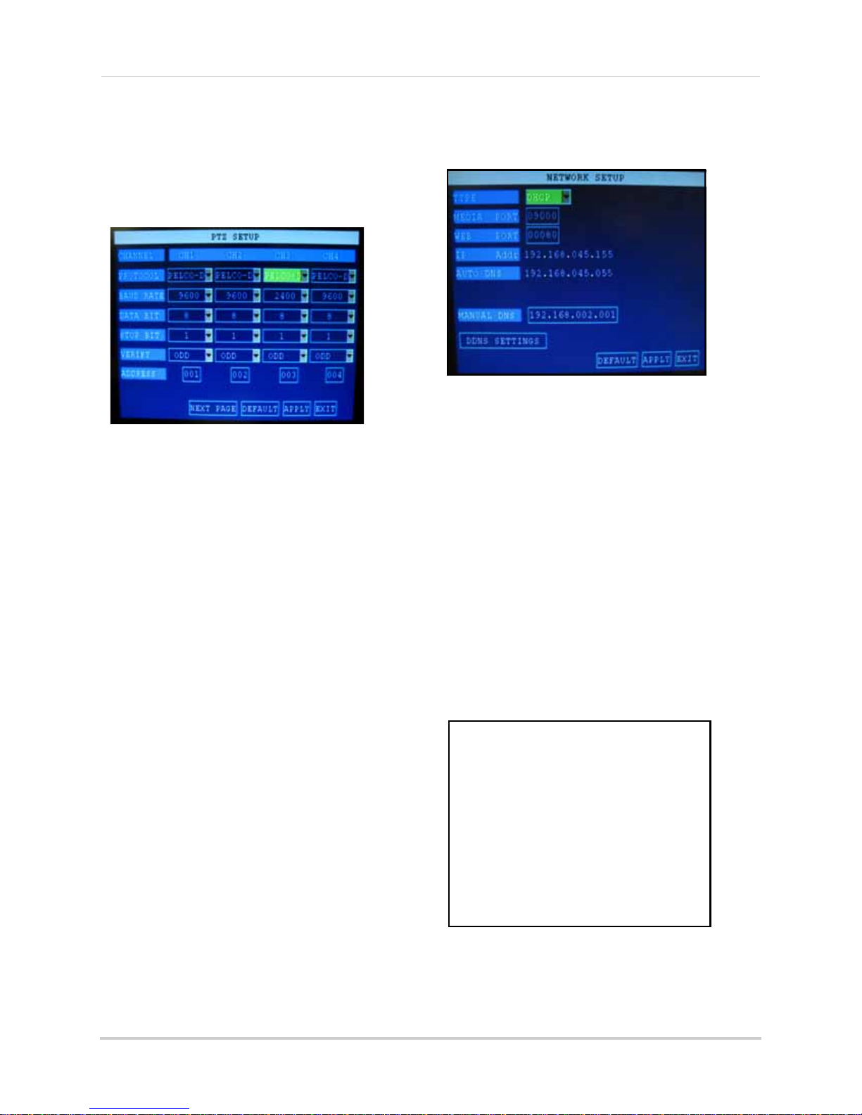
Using the Main Menu
Figure 20.0 PTZ Setup menu
Figure 21.0 Network menu (DHCP default)
Figure 21.1 PPPoE setup
PTZ
Use the PTZ Setup menu to configure settings
for a connected PTZ camera (not included).
NOTE: Consult the instruction manual of your
PTZ camera for complete information about
your camera, including protocol and baud rate.
To configure a PTZ camera:
1. Connect a PTZ camera to the BNC and
485A
(TX, +) and 485B (RX, -) ports and
power outlet. For more details on
connecting a PTZ camera, see “Appendix
D: Connecting a PTZ CAMERA” on page 53.
2. Under PROTOCOL, select PELCO-D or
PELCO-P for
NEXT PAGE for additional channels
(8-channel models only).
3. Under BAUD RATE, select 1200, 24
4800, or 9600.
4. Under DATA BIT select 5, 6, 7, or 8.
5. Under STOP BIT, select 1 or 2.
Under VERIFY, select ODD, EVEN, MARK,
6.
SPACE, or NON
7. Under ADDRESS, enter an address from
001~2
55 using the Virtual Keyboard. Refer
to your PTZ camera’s instruction manual
for further details.
8. Click APPLY. Click CLOSE in the
c
onfirmation window.
9. Click EXIT in all menus until all
are closed.
the selected channel. Click
00,
E.
windows
NETWORK
Use the Network Setup menu to configure your
network and DNS settings.
To configure network settings:
1. Under TYPE, select DHCP (d
PPPoE, or STATIC. If DHCP, go to
PPPoE, go to
NOTE: DHCP allows you to quickly connect to
your network by obtaining an IP address from
the router. After the initial setup, we recommend
that you disable DHCP and set the IP address
between 1~100. For example, if your IP address
is 192.168.0.107, change the last digits to 90 (i.e.
192.163.0.90). This ensures that port forwarding
will not change in the event of power failure or
resetting of your network.
2. If you select
step 2
PPPoE
. If STATIC, go to
in step 1, enter your
PPPoE user name and password in the
respective fields using the Virtual
Keyboard.
efault),
step 5
. If
step 3
.
25
Page 39

Using the Main Menu
Figure 21.2 Primary DNS from router’s WAN settings
ATTENTION: You MUST enter your DDNS
information LOCALLY before attempting
remote access.
Figure 21.3 DDNS setup
3. If you selected
STATIC
in step 1, enter your
IP Address, Netmask, and Gateway in the
respective fields using the Virtual
Keyboard.
NOTE: The default IP address of the system is
192.168.3.97
4. If necessary, change the Media and Web
Ports.
NOTE: For added security, we strongly
recommend changing Web port 80 on the system
to any desired port not blocked by your Internet
s e r v i c e p ro v i d e r ( I S P ) . P l e a s e n o t e h o w ev e r , t h a t
you will also need to update the Web port in your
browser and open this new port in your router.
For details on changing ports on your system,
see “Appendix C: Changing Ports On Your
System” on page 49.
5. Click APPLY. Click CLOSE in the
confirmation window.
6. Click EXIT in all
menus until all windows
are closed. The system restarts
automatically.
DDNS SETTINGS
Lorex provides a free DDNS service for use
with your DVR. A DDNS account allows you to
set up a web site address that points back to
your Local Network.
NOTE: You must register for Lorex’s free DDNS
service prior to configuring DDNS settings. Visit
http://lorexddns.net to r
egister.
Manual DNS
Enter the Primary or Secondary DNS from
your router. This is required for DDNS to
function properly.
To obtain your Primary or Secondary DNS:
1. In your web browser, log in to your router
using its Def
NOTE: Refer to your router’s manual or software for
login information. You can also get the Default
Gateway on your PC by selecting Start
cmd and press Enter. In the Command Prompt
window type ipconfig and press Enter.
2. View its WAN settings. Enter the Primary
or Secondary DNS address in the MANUAL
DNS field on your system.
ault Gateway address.
>Run. Type
To configure DDNS settings:
1. From the Network Setup menu, enter
Primary or Secondary DNS fr
om the WAN
settings of your router in the MANUAL
DNS field. See “Manual DNS” on page 26.
2. Click DDNS
SETTINGS.
3. Under DDNS, select ON.
4. Under SERVICE, select LOREX.
5. Under DOMAIN NAME, enter only the first
portio
n of your DDNS domain from the
confirmation email. For example, if your
domain name is tomsmith@lorexddns.net,
you only need to enter
tomsmith
in the text
field.
6. Enter your Lorex DDNS user name and
pa
ssword in the respective fields.
NOTE: Obtain this information from the
confirmation email after registering for the free
Lorex DDNS service.
7. Click APPLY. Click CLOSE in the
confirmation window.
8. Click EXIT. The syst
em will prompt you
that it must restart. Click CLOSE.
NOTE: Please allow 10~15 minutes for the DDNS
servers to update with your new DDNS address.
This is normal for the DDNS system.
26
Page 40

REMOTE SURVEILLANCE SOFTWARE
Figure 22.0 Remote Surveillance main screen
The system features a built-in browser-based software that allows you to access your system
®
remotely over your local area network (LAN) or over the Internet using Internet Explorer
.
System Requirements
Prior to using DVR Netviewer, make sure your PC meets or exceeds the following system
requirements:
Description Requirement
CPU Pentium
Operating
System
Memory 256 MB RAM or greater
Video 16 MB of video memory
Network (LAN) 10/100 BaseT Network
Network
(WAN)
Browser Internet Explorer 6 (or later)
Media Player Windows Media Player
Windows XP/Vista
38
*High-speed Internet service is recommended when using DVR Netviewer.
®
4 or above
4 Kbps upstream*
®
10 or above
27
Page 41

USING REMOTE SURVEILLANCE
Figure 23.0 Click the ActiveX attention bar
Figure 23.1 Remote access login screen
With your system connected to your local area network, you can now log in to your system using
Internet Explorer.
NOTE: Your system must be connected to your local or wide area network before attempting remote
access.
Logging In to Your System
With your IP address, you can now log in to your system over your local or wide area network.
NOTE: You must configure DDNS settings locally. For details on setting up DDNS, see “DDNS SETTINGS”
on page 26.
To access your system:
1. Open Internet Explorer. In the address bar, enter the IP addr
ess of your system (i.e.
192.168.3.97). For details on how to find your IP address, see “How do I find my IP and MAC
addresses?” on page 42.
®
2. You must install the ActiveX
in order to access your system. Click the attention bar at the top
of the main page and select Install ActiveX Control. DVR Netviewer will reset.
3. In the warning box click Install. The l
4. Leave the password field blank (def
NOTE: If you have enabled passwords on your system, enter your USER or ADMIN password. However,
only the ADMIN can change settings and options on the system.
ogin page appears.
ault).
5. Select LAN or INTERNET from the drop-down menu and click LOGIN.
28
Page 42

Using Remote Surveillance
Figure 23.2 DVR Netviewer main screen
4
8
6
7
1
3
5
2
Remote Surveillance Main Screen
Upon login, the Remote Surveillance main screen appears in your browser.
1. Modes: Cl
2. Main Screen: Main
3. Time Stamp:
4. Channel: Channel number appear
5. PTZ Control: PTZ control
6. Functions: Click the
7. Display Modes: Click the icons to view channels in single-channel full-screen, quad, and
split-screen configurations.
8.
Volume/Mute: Select a channel (outlined in red) and then click the bars to increase/decrease
volume; click the icon to mute/unmute volume.*
*Audio capable cameras (not included) required for audio listening and recording.
ick LIVE, REPLAY (playback), and SETUP.
display screen for live viewing and playback.
Time stamp appears on each channel.
s in the top left corner.
for any connected PTZ cameras (not included).
icons to show/hide channels, take screen captures, and record.
29
Page 43

Using Remote Surveillance
**
Figure 24.0 Live Viewing controls
Figure 24.1 Sub-menu
Figure 24.2 PTZ control
Live Viewing
By default, remote
surveillance opens
in Live Viewing mode
(split-screen).
To use Live Viewing:
1. Click LIVE at
top of the main
screen.
2. Click the display
mode icons t
view the main
screen in
single-channel, quad, or split-screen
configurations. You can also double-click a
channel at any time to view it in
single-channel.
3. Click to show or hide all the channel
windows.
4. Click to start/stop manual recording
to your PC on ALL channels. For more
details see RECORDING.
5. Select a channel (outlined in red) and then
click the
decrease listen-in volume. Click the icon
to mute/unmute.*
NOTE: The Talk function is not supported.
o
audio
the
bars to increase or
Sub-Menu
Right-click any channel to open the sub-menu.
The sub-menu contains the following options:
• Open Window
• Close
• Open All
• Cl
ose All
• Start Record
• Stop
PTZ Control
You must have a PTZ
camera (not included)
connected to the
system in order to use
the PTZ controls.
To control a PTZ
camera:
RECORDING
You can record video directly to your PC using
the remote surveillance software.
To record video to your PC:
*Audio capable camera (not included) required for listen-in audio.
**2-way audio not supported.
30
• From Live Viewing, click to start/stop
manual rec
ording to your PC on ALL
channels
NOTE: You will record video to your PC
regardless of the recording mode on the system
itself. By default, recorded files are saved in
C:\DVR\[ip_address]\Record
1. Select the channel
of the
onnected
c
PTZ camera(s).
2. Click the
navigation arrows
pan and tilt the
to
camera.
3. Click + /- to co
ntrol
zoom, focus, and iris.
4. Enter presets.
5. Click SETTING, HAND, and CLEA
further control presets.
R to
Page 44

Using Remote Surveillance
Figure 24.3 Screen capture save path
Figure 25.0 Playback screen
Figure 25.1 Progress bar
Taking Screen Captures
Use the remote surveillance software to take a
snapshot of the channels on the main display
screen. Screen Captures can be useful for your
own records, or may be needed by authorities
in case of a security incident.
To take a screen capture:
1. From Live Viewing, select the channel you
o capture. The selected channel will
want t
be highlighted in a red frame.
2. Click .
e
3. Click OK in th
confirmation window.
Screen captures are saved as BMP files to the
default save location (
C:\DVR\...).
Playback
Use the Replay menu to search and playback
recorded video on your system and convert
saved video files to AVIs.
3. Double-click a file from the File List to
playback the file in the main screen. The
icon in the file list changes to "
X".Control
playback using the buttons at the bottom
of the main screen.
purple bar
The
progress. The
indicates the download
green marker
indicates
playback progress. You can click and drag the
playback marker (will turn from green to
orange) to advance or rewind playback as
needed.
• : Play/Pause playback
• :
Stop playback
• : Fast Forward (click repeatedly for
1X, 2X, 4X, 8X)
• : Slow motion (click repeatedly for
1X, -2X, -4X, -8X)
• : Pause playback—click repeatedly
to advance frame-by-frame
• : 264 TO AVI Click to convert the
recorded video file to AVI format. For more
details see “Appendix J: Converting Files
to AVI” on page 61.
To use the replay menu:
1. Click REPLAY at
the top of the main
screen. The main screen will be grey.
2. Click REFRESH b
elow the calendar to view
the recorded files for the current month.
NOTE: Normal recording is indicated by a clock
icon; alarm recording (alarm, loss, and motion
events) are indicated by an exclamation mark
icon.
31
Page 45

Using Remote Surveillance
Figure 25.2 File List
Figure 26.0 If viewing a file, wait for it to
load before backing it up
Figure 26.1 Backup confirmation
Search
Use the calendar and
drop-down menus to
search for recorded
video on your system.
1. Click <> to chan
the month on the
calendar. Dates with
recorded video data
will appear in bold.
2. Click the date.
ded video files
Recor
will populate the File
List.
3. From the
Channel
drop-down menu,
select a specific
channel or select ALL CHANNEL and then
click SEARCH.
4. From the
Type
COMMON (normal recording), ALARM, or
ALL TYPE and then click SEARCH.
5. Double-click the file from the File List to
playback the file
ge
drop-down menu, select
in the main screen.
Remote Backup
You can backup recorded video files from your
system to your PC using the Replay menu in
the remote surveillance software.
To backup files remotely:
1. Click RE
screen.
2. Select a date(s) on the calendar and click
REFRESH.
3
. Double-click a file from the File List to
begin play
4. Click BACK
[ip_address]/Backup
NOTE: If you playback a file, you must wait for
the file to load before backing it up, otherwise
you may receive an error message (see figure
0.0).
Y at the top of the main
PLA
back.
UP. Backup begins to C:/DVR/
5. When file backup is complete, click OK in
the confirmation window. The confirmation
window show the save path of the backup
file.
NOTE: Backup files are saved as .264 files.
NOTE: Use th
software CD to playback backed up video. For
more details, See “Appendix K: Playback
Software” on page 62.
e Player Software included on the
32
Page 46

Using Remote Surveillance
• RECORD
• ALARM
• PTZ
• NETWORK
• SETTING
• HOST INFO
Figure 27.0 Record menu
Remote Setup
Use the Setup tab to configure the settings of
your system from a remote location.
NOTE: If the Main Menu is open on the system,
you will not be able to make changes to the
system from the remote location.
To open remote setup:
• Click SETUP at the top of the main
The Remote Setup menu features the
following tabbed options:
RECORD
The Record tab allows you set recording
parameters on the system as well as program
a recording schedule.
• CHANNEL: Click the dr
the respective channels and select ON/
OFF to enable/disable recording. If OFF,
the channel will not record
NOTE:
additional channels (8-channel models
only)
Click NEXT and PREVIOUS to view
• RESOLUTION: Check (non-selectable)
• QUALITY: Select BEST, FINE, or NORMAL
• AUDIO: Select ON/OFF
NOTE:
included) are required for audio recording.
Audio capable cameras (not
op-do
screen.
wn menus for
continuously whenever the system is
restarted; if you select TIMER RECORD,
you can click SCHEDULE to program a
recording schedule
• SCHEDULE (TIMER RECORD must be
selected):
Click DEFAULT to
Click APPLY to s
restore factory settings.
ave your changes and then
click OK in the confirmation window.
SCHEDULE
To enter a recording schedule remotely:
1. Click SETUP at the top of the main scr
The Record menu opens by default.
2. Under REC. MODE
, select TIMER RECORD
and then click SCHEDULE. The Schedule
window opens.
3. From the drop-down menu at the top of the
window
, select the desired channel or
select ALL.
4. At the bottom of the window, select either
ALARM, NORMAL, or NO (n
o recording).
5. Click the time blocks from 0~23 for the
ed
desir
day of the week.
• : (blue) selected block
• :
(red) alarm
• : (green) normal
• : (clear) no recording
6. From the COPY/SET TO dr
op-down menus
to copy the schedule of one day to another.
For example, if you want your schedule for
Monday to be the same on Wednesday:
under COPY select MON, under SET TO
select WED, and then click COPY.
7. Click APPLY and
then click OK in the
confirmation window.
8. Click EXIT to
close the Schedule window.
een.
• REC. MODE: Select POWER UP or TIMER
RECORD; if your select POWER UP, the
system will automatically begin recording
33
Page 47

Using Remote Surveillance
Figure 28.0 Record menu
Figure 28.1 Motion Grid
ALARM
The Alarm tab allows you to configure alarm
settings as well as set motion detection.
To open Alarm setup:
• Click SETUP at the top of the
and then click ALARM.
Configure the following alarm and motion
ction settings for each respective channel:
dete
NOTE:
additional channels (8-channel models
only)
Click NEXT/PREVIOUS for
main screen
• PO
ST REC: Set
after an alarm is triggered—30s, 1min, 2min, or
5min
the time for the system to record
Click APPLY to save your settings and then
click OK in the confirmation window.
MOTION GRID
To set the motion grid:
1. Click SETUP at the
and then click ALARM.
2. Under MOTI
ON AREA, click SETUP for
each respective channel you wish to apply
motion detection. The Motion Grid opens.
NOTE: Click NEXT/PREVIOUS for additional
channels (8-channel models only).
top of the main screen
• I/O ALARM: Select NO (normal open), NC
(normal close) or OFF
• MOTION DETECT: Configure the following:
• STATUS: Select ON/OFF to enable/disable
motion detection
• SENSITIVITY: Sel
NORMAL, or LOW
• MD (motion d
open the Motion Grid (see Motion Grid on page 36)
ect HIGHEST, HIGH,
etection) AREA: Click SETUP to
• VIDEO LOSS: Select ON/OFF to enable/
disable the alarm when a camera is
disconnected
• HDD SPACE: Select ON/OFF to enable/
disable the alarm when the hard drive is
full (Overwrite must be turned off)
• HDD LOSS: Select ON/OFF to enable/
disable the alarm is the internal hard drive
is damaged or incurs failure
• ALARM MANAGE: Configure the
following:
• OUTPUT: Set the time (in seconds) for the
buzze r to soun d when a n a lar m is t ri ggere d— 0s,
10s, 20s, 40s, or 60s
3. Click the blocks to enable/disable motion
detection. RED=motion detection
BLACK=motion detection
disabled
enabled
. You can
click and drag to select multiple blocks;
click CLEAR to disable all the blocks.
4. Click CONFIRM an
d then click OK in the
confirmation window.
;
34
Page 48

Using Remote Surveillance
Figure 29.0 PTZ menu
Figure 30.0 Network menu
Figure 30.1 PPPoE setup
PTZ
The PTZ tab allows you to configure the
settings for connected PTZ cameras (not
included).
NOTE: Please refer to the instruction manual of
your PTZ camera for complete details on
configuring your camera settings.
To open PTZ setup:
• Click SETUP at the top of the
and then click PTZ
Configure PTZ settings for each channel with a
connected
NOTE: Click NEXT/PREVIOUS for additional
channels (8-channel models only).
PTZ camera (not
• PROTOCOL: Select PELCO-D or PELCO-P
• ADDRESS: Select from 1~255
• BAUD RATE: Select 1200, 2400, 4800, or
9600
• DATA BIT: Select 5, 6, 7, or 8
• STOP BIT: Select 1 or 2
• VERIFY: Select ODD, EVEN, MARK,
SPACE, or NONE
main screen
included):
NETWORK
The Network tab allows you to configure your
IP and DDNS settings.
To open Network setup:
• Click SETUP
and then click NETWORK
To configure IP settings:
1. Under TYPE, select DHCP (def
PPPoE, or STATIC. If
PPPoE, go to
NOTE: DHCP allows you to quickly connect to
your network by obtaining an IP address from
the router. After the initial setup, we recommend
that you disable DHCP and set the IP address
between 1~100. For example, if your IP address
is 192.168.0.107, change the last digits to 90 (i.e.
192.163.0.90). This ensures that port forwarding
will not change in the event of power failure or
resetting of your network.
2. If you select
PPPoE user name and password in the
respective fields.
at the t
step 2
PPPoE
op of the main screen
ault),
DHCP, go to
. If STATIC, go to
step 5
step 3
in step 1, enter your
. If
.
Click APPLY to
save your settings and then
click OK in the confirmation window.
35
Page 49

Using Remote Surveillance
Figure 30.2 Static IP setup
ATTENTION: You
MUST
enter your DDNS
information
LOCALLY
before attempting
remote access.
Figure 30.3 DDNS setup
3. If you selected
STATIC
in step 1, enter your
IP Address, Netmask, and Gateway in the
respective fields.
NOTE: The default IP address of the system is
192.168.3.97
4. If necessary, change the Media and Web
Ports.
NOTE: For added security, we strongly
recommend changing HTTP port 80 on the
system to any desired port not blocked by your
Internet service provider (ISP). Please note
however, that you will also need to update the
Web port in your browser and open this new port
in your router. For details on changing ports on
your system, see “Appendix C: Changing Ports
On Your System” on page 49.
5. Click APPLY to save your settings and then
click OK in the confirmation window.
DDNS
Lorex provides a free DDNS service for use
with your DVR. A DDNS account allows you to
set up a web site address that points back to
your Local Network. You must register for
Lorex’s free DDNS service prior to configuring
DDNS settings.
3. In the HOST NAME field, enter only the
first portion
of your DDNS domain from
the confirmation email. For example, if
your domain name is
tomsmith@lorexddns.net, you only need to
enter
tomsmith
NOTE: Obtain this information from the
confirmation email after registering for the free
Lorex DDNS service.
in the text field.
4. Enter your Lorex DDNS user name and
password in their respective fields.
5. Click APPLY t
o save your settings and then
click OK in the confirmation window.
6. To ensure your DDNS settings are saved
y
our system, disconnect the power
on
cable from the rear panel of your system.
Allow the system to power down for 15~20
seconds. Reconnect the power cable.
NOTE: Please allow 10~15 minutes for the DDNS
servers to update with your new DDNS address.
This is normal for the DDNS system.
Visit http://lor
exddns.net to register for
Lorex’s free DDNS service. For more details on
setting u
p a free Lorex DDNS account, see
“Setting Up DDNS Service” on page 44.
To change DDNS settings:
1. Under DDNS, select ON.
2. Under SERVICE, select LOREX.
36
Page 50

Using Remote Surveillance
Figure 31.0 Settings menu
Figure 31.1 Network password clear in the system menu
SETTINGS
Use the Settings menu to enable/disable
network passwords, set the save location for
backup files, and configure Daylight Savings
Time settings.
To open Settings:
• Click SETUP and the t
screen and then click SETTINGS
Configure the following:
• INTERNET BANDWIDTH: Sel
192K, 256K, 384K, 512K, or 1024K
NOTE:
on the bandwidth capacity of your local or
wide area network. Consult your Internet
Service Provider (ISP) for more information.
Adjust the bandwidth setting based
• FILE SAVEPATH: By default, the system
is set to save all data to
to browse for a new save location
• DST: Select ON or OFF to enable/disable
Daylight Savings Time.
• DST MO DE: Select DEFAULT or select CUSTOM.
• START: If you select CUSTOM, you can set the
Start and Stop times for DST. From the
drop-down menu, select 1ST WEEK ~ 4TH WEEK.
From the Sunday drop-down menu, select
JANUARY~DECEMBER.
• EN
D: F
rom the drop-down menu select 1ST
WEEK ~ 4TH WEEK; from the Sunday drop-down
menu select JANUARY~DECEMBER
op of the main
ect 128K,
C:\DVR\. Click
Setting a Network Password
By default, the system is designed to allow you
to use your system password (if enabled) as
your network password for remote
surveillance. If desired, you can set a Network
Password only for use with the Remote
Surveillance Software.
To set a Network Password:
1. Under IE PASSWORD ENABLE, select ON.
and
2. Enter 6-digit alpha/numeric USER
ADMIN passwords in their respective
fields. Re-enter the passwords to confirm.
3. Click APPLY.
If you forget the network passwords, you can
clear the network password
on your system to
allow you to login with your standard system
password.
NOTE: The network password can only be
cleared on the system itself—not through
remote surveillance using Internet Explorer.
To clear the network password:
1. On the system, open the MAIN ME
then click BASIC.
2. From the Basic Setup menu click
PASSWORD.
3. Select the box beside NETWORK PW
CLEAN.
4.
Click APPLY. Click CL
OSE in
the
confirmation window.
Your network password has been cleared. You
can no
w access your system remotely using
the system passwords.
NU and
• Click APPLY to save your settings and then
click OK in the confirmation window.
37
Page 51

Using Remote Surveillance
Figure 32.0 Host Info menu
HOST INFO
Use the Host Info menu to view important
information about the status of your system.
HDD Status: The bar will fi
ll from left to right to
indicate the storage space used on the HDD.
Recording hours available (based on curr
ent
settings):
Firmware version:
MAC address (t
he physical address of your
system on your network):
38
Page 52

APPENDIX A: SYSTEM SPECIFICATIONS
DVR
Image size 384-768 Kbyte (CIF)
Video inputs 8 x 1.0Vp-p, CVBS, 75ohms, BNC
Video outputs VGA, BNC x 2
Audio inputs 8 x line-in, RCA
Audio output 1 x line-out, RCA
Supply voltage 100VAC-240VAC, 19VDC@ 3.42A, 50/60Hz
Power consumption Approx. 25 watts (with HDD)
Operating Temp. Range 0° ~ 50° C
Hard disk capacity 1 HDD (Max 1TB)
Operating System Linux (embedded)
Backup USB Default (USB memory flash drive)
Back-up file formats H.264 (special formats)
Compression H.264
Recording resolutions 360x240
Recording speed 360x240 : 240fps (NTSC), 360x288 : 200fps (PAL)
Record Scheduling Daily, Weekly adjust specific Hr per channel
Pre/Post alarm recording MAX 1 minutes (Post)
Playback Single channel
Alarm inputs 8 x voltage inputs, programmable as NC/NO
Alarm outputs 1 x voltage outputs; 12VDC/0.2A,
Activity detection 13x8 grid
@ NTSC, Sensitivity levels: 4
PTZ Control RS-485 interface
Unit Weight 2.5 kg
Unit Dimensions 300mm X 250mm X 60mm (W X D X H)
Networking
Remote Functions Live View, Live Recording, Search, Set-up, Back-up
Network Speed Control 6 levels (128-1024kb)/sec.
Network Protocol TCP/IP, DDNS and Web
Network Interface 10/100-Base-TX, RJ-45
Specifications:
As our products are subject to continuous improvement, Lorex Technology Inc. and its
subsidiaries reserve the right to modify product design, specifications, and prices without notice
and without incurring any obligation.
E&OE
39
Page 53
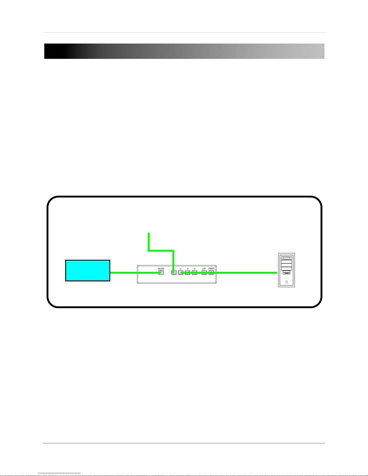
APPENDIX B: SETTING UP LOCAL AND REMOTE
ROUTER
(Not Included)
INTERNET
DVR
PC
(Not Included)
VIEWING
You can connect the system to a network for local or remote viewing. Once connected, you can
access your system locally or remotely using the DVR Netviewer client with Internet Explorer. The
default IP address of the system is 192.168.3.97
NOTE: Experience with routers and networking are recommended if configuring the network functions
of the system.
What do I need?
• DVR System
• PC with Internet Explorer 6 or later
NOTE: A router (not provided with the system) and a High Speed Cable or DSL Internet connection (for
remote viewing outside your network)
40
Page 54
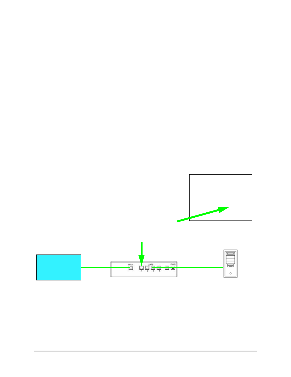
Appendix B: Setting up Local and Remote Viewing
ROUTER
(Not Included)
PC
(Not Included)
(not required for
local viewing)
INTERNET
Network Setup / Remote Access Overview
1. With the system powered off, connect your system to a router using the included Ethernet
cable. Power on the system.
2. Find the IP and MAC addresses of your system.
3. Enable Port Forwarding on your router (remote viewing only). see “How do I enable port
forwarding?” on page 43.
NOTE: All routers are different: please refer to your router’s manual for complete details on port affording
your router.
4. Setup an account at http://lorexddns.net
5. Enable DDNS on your sys
Use the Networking Checklist on page 47 to confirm you have completed all the necessary steps
of the networking process.
tem (log in
locally
and then power off and power on your system).
Connecting to a Network
To connect to a network:
1. Power off your system by disconnecting the power cable from the rear panel.
2. Connect an Ethernet cable (included) to the LAN port on the rear panel of the system.
Connect the other end of the Ethernet c
your router.
able to an empty LAN port (usually numbered 1~4) on
3. Reconnect the power cable to power the system back on.
41
Page 55

Appendix B: Setting up Local and Remote Viewing
Figure 33.0 IP address and MAC address
How do I find my IP and MAC addresses?
The IP and MAC address of your system are necessary for DDNS setup. DDNS allows you to view
and control your system from a remote location.
NOTE: Make sure you have connected the DVR to your local or wide area network via the LAN port on
the rear panel of the system.
To find your IP address: and MAC address:
1. Press the OK button
find your IP address and MAC address.
2. Press the OK
butt
on the front panel. The System Information menu opens. Here you will
on to close the menu.
Finding Your External IP Address
If you wish to find your external IP address, you can use a third-party website such as
www.showmyip.com. Your external IP address can also be found within your Router settings.
Refer to your router user guide for further details.
42
Page 56

Appendix B: Setting up Local and Remote Viewing
PC
Internal IP
192.168.0.2
DVR
Internal IP
192.168.0.3
Router
Internal IP
192.168.0.1
Router
External IP
216.13.154.34
Internal NetworkInternet
How do I enable port forwarding?
You need to enable port forwarding on your router to allow for external communications with your
system for the following port:
• 80 (HTTP port)
• 90
00 (Media Port)
NOTE: For added security, we strongly recommend changing HTTP port 80 on the system to
—the port must not blocked by your Internet service provider (ISP).
port
Computers, DVRs, and other devices inside your network can only communicate directly with each
other within the internal network. Computers and systems outside your network cannot directly
communicate with these devices. When a system on the internal network needs to send or receive
information from a system outside the network (i.e. from the Internet), the information is sent to
the router.
NETWORK EXAMPLE
any desired
When a computer on the Internet needs to send data to your internal network, it sends this data
to the external IP address of the router. The router then needs to decide where this data is to be
sent to. This is where setting up Port Forwarding becomes important.
Port Forwarding tells the router which device on the inte
you set up port forwarding on your router, it takes the data from the "external IP address:port
number" and sends that data to an "internal IP address:port number" (i.e Router External IP
216.13.154.34 to DVR Internal IP 192.168.0.3:80).
The instructions found online in the Router Configuration Guides
forwarding configurations for a selection of different router models. Visit our Consumer Guides
Support website at http://www.lorexcctv.com for more details.
rnal network to send the data to. When
will assist you in the port
43
Page 57

Appendix B: Setting up Local and Remote Viewing
Figure 34.0 Create a DDNS account
Figure 34.1 Enter personal information
Figure 34.2 System information
Setting Up DDNS Service
Lorex offers a free DDNS service for use with your system. A DDNS account allows you to set up
a web site address that points back to your Local Network. The following outlines how to set up
your free Lorex DDNS account.
To setup your free Lorex DDNS account:
1. In your browser, go to http://lorexddns.net and
click Create Account.
2. Complete the Account Information field
your personal information. Complete the
Warranty Information with your purchase
details (optional).
3. Complete the System Information fields:
ect y
• Product License: Sel
our product model
from the Product License drop down menu
(e.g. LH108)
•
<Product Code> - <MAC Address>: The
physical address of your product on your
network. Do not include hyphens/dashes.
• URL Request: Choose a URL for your DDNS
connection (i.e. your name, your company or
business name, or anything of your choice.)
s
with
4. Once the information has been entered, click
Cr
New Account.
eate
5. Your Account information will be sent to you at
the email Addr
ess you used in Step 2.
44
Page 58

Appendix B: Setting up Local and Remote Viewing
Username:
Domain name*:
Password:
* Only the first part of the Domain Name is required for setup on the system. For
example, if the full domain sent is
tomsmith.lorexddns.net
, you only need to enter
tomsmith on the system.
You will need this information for remote access to your system. Record your information below:
45
Page 59

Appendix B: Setting up Local and Remote Viewing
Figure 35.0 DDNS setup on the system
ATTENTION: You
MUST
enter your DDNS
information
LOCALLY
before attempting
remote access.
How do I enable DDNS on my system?
Once you have registered for free DDNS service, use the information in the confirmation email to
configure DDNS settings on your system
You can enter your DDNS information directly on your system (recommended) or using the built-in
the
remote surveillance software. If using
your DDNS on your local network (i.e. not over the Internet).
remote surveillance software, however, you must enter
To enable DDNS on your system:
1. Open the MAIN MENU and click
ADVANCE
.
2. From the Advanced Setup menu, click NETWORK.
3. From the Network Setup menu, enter the Primary or Secondary DNS fr
om the WAN settings
of your router in the MANUAL DNS field. See “Manual DNS” on page 26.
4. Click DDNS SETT
INGS.
5. Under DDNS, select ON.
6. Under SERVICE, select LOREX.
7. Under DOMAIN NAME, enter only the firs
t portion of your DDNS domain from the
confirmation email. For example, if your domain name is tomsmith@lorexddns.net, you only
need to enter
tomsmith
8. Enter your Lorex DDNS user name and password in
NOTE: Obtain this information from the confirmation email after registering for the free Lorex DDNS
service.
in the text field.
the respective fields.
9. Click APPLY. Click CLOSE in the confirmation window.
10. Click EXIT in all
menus until all windows are closed.
11. To ensure your DDNS settings are saved on your system, disconnect the power cable from the
rear panel of y
our system. Allow the system to power down for 15~20 seconds. Reconnect the
power cable.
NOTE: Please allow 10~15 minutes for the DDNS servers to update with your new DDNS address. This
is normal for the DDNS system.
For details on how to enable DDNS on your local network using the built-in remote surveillance
software, see “DDNS” on page 36.
46
Page 60

Appendix B: Setting up Local and Remote Viewing
Networking Checklist
Use this checklist to confirm you have completed all the steps of the Network Setup.
I have the following:
• High-Speed Internet
• Router
• Ethernet cable (included with the sys
• Computer with Internet Explorer 6 or later
I have turned off the system and performed the following:
• Connected the Ethernet cable to the LAN (RJ45) port on the rear panel of the system
• Connected the other end of the Ethernet cable to my router
NOTE: Network Setup will not work if you do not have a router.
I have found my System Information:
• Open the Main Menu and then click ADVANCE. Click NETWORK. Your IP address appears below
the Media and Web port
• Open the Main Menu and then click ADVANC
serial number
tem)
E. Click INFO. Your MAC address appears above the
My IP Address is: ________________________________________________
My MAC Address is: ______________________________________________
I have enabled Port Forwarding on my router:
• Port 80
• Port 9000
NOTE: For added security, we strongly recommend changing HTTP port 80 on the system to
—the port must not blocked by your Internet service provider (ISP). For details on changing your
port
ports, see “Appendix C: Changing Ports On
NOTE: Each router is different, so port forwarding settings vary by model. Please visit us on the web at
ww
w.lorexcctv.com f
to your router's manual or contact your router's manufacturer for assistance.
or assistance with the latest types of routers. If your router is not listed, please refer
Your System” on page 49.
any desired
47
Page 61

Appendix B: Setting up Local and Remote Viewing
ATTENTION: You
MUST
enter your DDNS information
LOCALLY
before
attempting remote access.
I have configured DDNS for remote access to my system:
Go to www.lorexddns.net and create a new account
Domain: ____________________________________
User ID: ____________________________________
Password: __________________________________
I have configured my system to connect to the DDNS server:
To enable DDNS on your system:
1. Open the MAIN MENU and click
ADVANCE
.
2. From the Advanced Setup menu, click NETWORK.
3. From the Network Setup menu, enter the Primary or Secondary DNS fr
om the WAN settings
of your router in the MANUAL DNS field. See “Manual DNS” on page 26.
4. Click DDNS SETT
INGS.
5. Under DDNS, select ON.
6. Under SERVICE, select LOREX DDNS.
7. Under DOMAIN NAME, enter only the firs
t portion of your DDNS domain from the
confirmation email. For example, if your domain name is tomsmith@lorexddns.net, you only
need to enter
tomsmith
8. Enter your Lorex DDNS user name and password in
NOTE: Obtain this information from the confirmation email after registering for the free Lorex DDNS
service.
in the text field.
the respective fields.
9. Click APPLY. Click CLOSE in the confirmation window.
10. Click EXIT in all
menus until all windows are closed.
11. To ensure your DDNS settings are saved on your system, disconnect the power cable from the
rear panel of y
our system. Allow the system to power down for 15~20 seconds. Reconnect the
power cable.
NOTE: Please allow 10~15 minutes for the DDNS servers to update with your new DDNS address. This
is normal for the DDNS system.
I can access my system from a remote PC:
To access your system remotely:
1. Open Internet Explorer and enter your DDNS addres
example,
tomsmith.lorexddns.net
2. Log in using your ADMIN password. If you have not enabled passwords on the system, leave
the password field blank.
48
s from the confirmation email. For
Page 62

APPENDIX C: CHANGING PORTS ON YOUR
Figure 36.0 Change the Web port
SYSTEM
For added security, we strongly recommend changing Web port 80 on the system to
—the port must not blocked by your Internet service provider (ISP).
port
NOTE:
Prior to changing ports on your system, you must connect your system to your network using the
included Ethernet cable.
Please contact your ISP for complete information on available ports in your area.
any desired
Example
Let’s say you want to change the Web port on your system from 80 to 85.
To change the port number:
1. Open the Main Menu and click ADVA
2. Click NETWORK.
3. Under WEB PORT, enter 0008
4. Click APPLY and then click CLOSE in
5. Click EXIT.
6. To confirm that the new port number is saved on your system, repeat steps 1~2. The new Web
port should appear on
The system will prompt you that it must restart. Click SURE.
the Network Setup menu.
5 using the Virtual Keyboard.
NCE. The Advanced Setup menu opens.
the confirmation window.
You must now include the new Web port number in the URL when logging in to your system with
Internet Explorer.
NOTE: Requires Internet Explorer 6 or later.
49
Page 63

Appendix C: Changing Ports On Your System
Figure 36.1 Enter :85 at the end of the IP address
Figure 36.2 Login with your LAN ID and password
Local Viewing:
To log in using the new port number:
1. Open Internet Explorer.
2. In the address bar, enter the IP address of your system immediately followed by :85 (no
es). For example, http://192.168.3.97:85
spac
3. Enter your system ADMIN password and
NOTE: If you have not enabled passwords on the system, leave the password field blank.
select LAN.
4. Click LOGIN.
50
Page 64

Appendix C: Changing Ports On Your System
ATTENTION: For remote viewing, the Web port and Media port of your system
MUST be port
forwarded on your router
—in this example, port 85 and Media Port 9000. Each router is
different, so port forwarding settings vary by model. Please refer to the Lorex Port
Forwarding Guide (www.lorexcctv.com/support and then click Consumer Guides) for help
on port forwarding your router. If your router is not listed, please refer to your router's
manual or contact your router's manufacturer for assistance.
Figure 36.3 DDNS
Remote Viewing
You should now be able to access your system from your local network. Prior to using remote
viewing, you must log in to your system locally and enter the DDNS information from your Lorex
DDNS confirmation email.
NOTE:
For details, see “Setting Up DDNS Service” on page 44.
To edit DDNS settings:
We strongly recommend registering for Lorex’s free DDNS service prior to using remote viewing.
1. From a PC on your local
network, open Internet Explorer.
2. In the address bar, enter the IP address of your system immediately followed by :85 (no
spaces). F
or example, http://192.168.3.97:85
3. Enter your system ADMIN password and select LAN.
NOTE: If you have not enabled passwords on the system, leave the password field blank.
4. Click LOGIN.
5. Click SETUP at the top of the
6. Under DDNS, select ON. Ent
main screen and then click NETWORK.
er your DDNS information from the confirmation email and click
APPLY. For complete details on entering your DDNS information, see “How do I enable DDNS
on my system?” on page 46.
7. Reset your system by disconnecting the power cable from the rear panel of the system. Let
the sys
tem power down for 15~20 seconds and then reconnect the power cable.
8. To confirm the DDNS settings have been saved to your system, open the Main Menu and click
a
ADVANCE. The Adv
nced Setup menu opens.
9. Click NETWORK and then click DDNS SETTINGS.
If y
ou have not already done so, port forward ports 85
and 9000 on your router. Each router is
different, so port forwarding settings vary by model. Please refer to the Lorex Port Forwarding
Guide (www.lorexcctv.com/support and then click Consumer Guides) for help on port forwarding
your router. If your router is not listed, please refer to your router's manual or contact your
router's manufacturer for assistance.
51
Page 65

Appendix C: Changing Ports On Your System
Figure 36.4 Enter :85 at the end of the DDNS URL
Figure 36.5 Login with your LAN ID and password
Remote Viewing (cont’d.)
Now that you have configured your DDNS settings, you should be able to log in to your system from
a remote PC (i.e. a PC not on your local network).
To log in using DDNS:
1. Using a remote PC, open Internet Explorer.
2. In the address bar, enter your DDNS a
NOTE:
Obtain your DDNS address from your confirmation email.
3. Enter your system ADMIN password and select INTERNET.
NOTE: If you have not enabled passwords on the system, leave the password field blank.
4. Click LOGIN.
ddress immediatel
y followed by :85 (no spaces).
NOTE:
and 9000 on your router. If you change Media Port 9000 on your system, you
corresponding port on your router
If you are having problems connecting using DDNS, check that you have port forwarded ports 85
.
MUST port forward the
52
Page 66

APPENDIX D: CONNECTING A PTZ CAMERA
DVR
PTZ CAMERA
(not included)
Figure 37.0 Connecting a PTZ camera (not included)
Figure 37.1 PTZ control
Figure 37.2 PTZ Senior control
You can connect RS-485 PTZ cameras (not included) to the PTZ Control Block on the rear panel of
the system. Additional PTZ cameras are available at www.lorexcctv.com
To install a PTZ Camera:
1. Connect the Transmit Cable to the 485A TX
2. Connect the Receive Cable to the 485B RX
3. Connect the video cable to a BNC port.
4. Open the MAIN MENU and then click ADVANCE. The Adv
5. Click PTZ.
6. Configure the settings based on the instructions of your PTZ camera and click APPLY.
NOTE: The PTZ camera settings depend on the type of PTZ camera. Please refer to the specific camera
manual for your brand and model of PTZ camera.
To use a PTZ camera:
1. Make sure the camera is properly connected and configured
prior to usi
2. From live viewing, right-click anywhere on
the sub-menu and select PTZ. The PTZ control panel opens.
3. Click the navigation keys to move the lens.
4. Click and drag the slider to adjust panning speed.
5. Click + / - to co
6. Click SETUP to
To use Senior Control:
1. Under Preset, enter a number using the Virtual Keyboard
(mouse onl
2. Click Clean Preset t
3. Click Call Preset t
4. Click Auto
scan.
5. Click EXIT t
(+) port of the PTZ block on the rear panel.
(-) port of the PTZ block on the rear panel.
anced Setup menu opens.
ng the PTZ camera.
the screen to open
ntrol Zoom, Focus and Iris.
open Senior Control.
Click Set Preset to save the preset.
y).
o erase a preset.
o set a preset.
Scan to scan for presets. Click Stop Scan to stop the
o close the Senior Control menu.
53
Page 67

APPENDIX E: CONNECTING MOTION/ALARM
DVR
SENSOR
(Not Included)
GROUND CABLE
ALARM CABLE
DEVICES
You can enable Motion Detection and Alarm control from the Main Menu. Use a motion detector
or sensor to send a signal to the system to trigger alarm recording on the corresponding camera
channel (when enabled in the Menu).
Installing a Sensor
To connect an external alarm sensor to the system:
1. Connect the Signal Cable to the desired Channel number port on the r
2. Connect the Ground Cable to a Ground port
on the rear panel.
ear panel.
54
Page 68
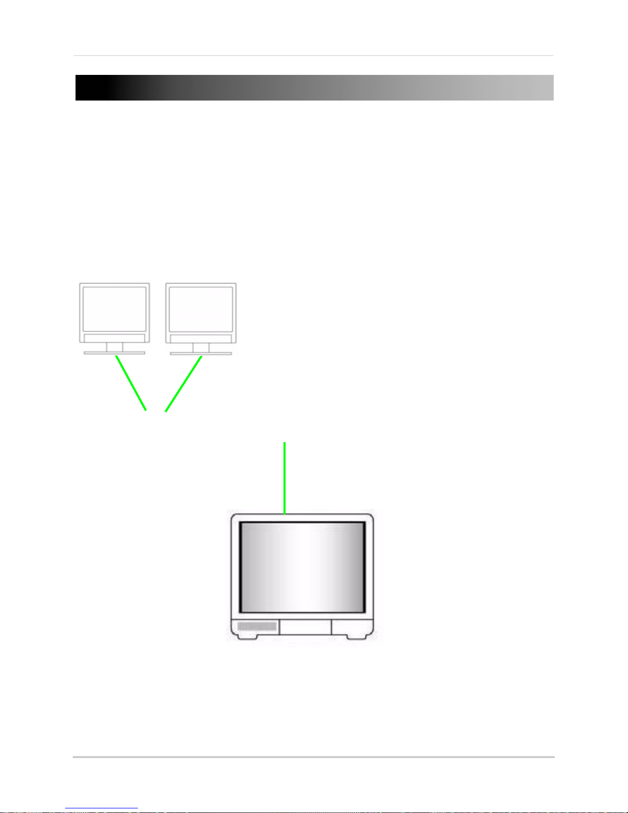
APPENDIX F: CONNECTING ADDITIONAL
DVR
EXTERNAL MONITORS (BNC)
(Not Included)
PRIMARY MONITOR (VGA)
(Not Included)
EXTERNAL MONITORS
Use the VIDEO OUTports (BNC) on the rear panel of the system to connect an external monitor(s).
Monitor-out mirrors the entire screen image of your system. This is useful if you need to monitor
the system from a second location (e.g. a back office).
L
55
Page 69

APPENDIX G: FULL CONNECTIVITY DIAGRAM
(Not Included)
PC
(Not Included)
(Not Included)
*8-channel model shown.
DVR
EXTERNAL MONITORS
(Not Included)
POWER
PTZ CAMERA
(Not Included)
BNC CAMERAS
VGA MONITOR
(Not Included)
AUDIO CAPABLE
CAMERA
(Not Included)
AMPLIFIED SPEAKERS
(Not Included)
SELF-POWERED
MICROPHONE
(Not Included)
The following diagram outlines a general set of connections available with the system*.
VIDEO OUT
12123456778
1234567
DC +19V
IN
8
ALM IN
VIDEO IN
VGARJ45
AUDIO OUT
AUDIO IN
3
1
4
2
5
8
5
56
Page 70

APPENDIX H: REPLACING THE HARD DRIVE
Figure 38.0 Remove cover
Figure 38.1 Disconnect the power and data cables, then remove the screws from the mounting brackets
The system comes with a pre-installed 3.5" SATA hard drive. You can expand the system with a
replacement single hard drive up to 1 terabyte (TB).
NOTE: Mak
ch
anging the hard drive.
Removing the Hard Drive
To remove the hard drive:
1. Remove the screws from the side panel (x2) and rear panel (x5) of the cover.
2. Gently slide the cover away from the rear panel and lift off.
e sure that the system is OFF and the power cable has been disconnected before
3. Disconnect the power and data cables.
4. Remove the screws from the mounting brack
5. Gently remove the hard drive from the housing.
ets (see figure 38.1).
57
Page 71

Appendix H: Replacing the Hard Drive
Figure 38.2 Secure the HDD to the mounting brackets and reconnect the power and data cables
Replacing the Hard Drive
To replace the hard drive:
1. Place the new drive in the housing. The connections end of the drive should face toward the
front panel (see figur
brackets.
NOTE: The cable from the exhaust fan will be underneath the drive.
2. Reconnect the power and data cables. Each cable can only be connected one way.
e 38.2). Replace the screws (x4) to secure the drive to the mounting
3. Replace the cover, tucking the lip of the cover at the front panel.
4. Replace the screws on the side and rear panels of the cover.
58
Page 72

Formatting the Hard Drive
ATTENTION: Formatting the HDD
erases
all data
on the hard disk.
This
step cannot be undone
.
Figure 38.8 Formatting warning
Appendix H: Replacing the Hard Drive
If you replace the pre-installed hard drive, it
must
be formatted in order to function properly with
the system.
To format the hard disk:
1. Right-click anywhere on the screen and select MAIN MENU.
2. Click HDD.
3. From the HDD Management menu click HDD FORMAT.
4. From the Warning prompt, click SURE. The sys
tem will begin formatting the hard drive. This
may take several moments depending on the size of the HDD.
the c
5. Once formatting is complete, click CLOSE in
onfirmation window. The system will
automatically restart and load to the default live viewing display.
6. Open the Main Menu and click HDD to che
NOTE: You will notice that the size of the HDD and the free space are not the same. The system uses a
portion of the disk space for the operating system and initialization. This is common in all security DVRs
as well as common PC hard drives.
ck the status of the hard drive.
59
Page 73
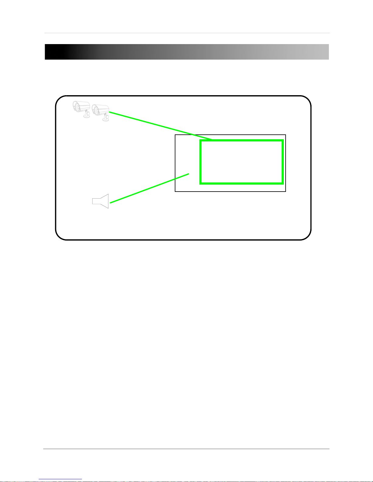
APPENDIX I: CONNECTING AUDIO
DVR
AUDIO CAPABLE
CAMERAS
(Not Included)
LINE OUT / AMPLIFIED SPEAKERS
(Not Included)
Use audio capable cameras (not included) to listen to, and record audio on the system*.
To connect audio:
1. Connect RCA audio cables from an audio capable camera(s) to the AUDIO I
panel of the system. The audio port should correspond to the matching VIDEO IN port (i.e.
Audio camera 1
2. Connect an RCA audio out cable to the AUDIO OU
3. Right-click anywhere on screen and select MAIN MENU.
4. Click REC
5. Under AUDIO, select ENABLE.
6. Click APPLY and then click CLOSE in
To adjust volume:
1. From the MAIN MENU click BASIC.
2. Click VIDEO/AUDIO.
3.
Click VOLUME S
4. Click each channel and click and drag the volume slider to incr
5. Click X to e
6. Click APPLY and then click CLOSE in
should be connected to
ORD.
ETUP.
xit.
Video In port 1
and
Audio In port 1
T port on the rear panel of the system.
the confirmation window.
the confirmation window.
N ports on the rear
).
ease/decrease the volume.
60
Page 74

APPENDIX J: CONVERTING FILES TO AVI
Figure 39.0 AVI Convert window
Figure 39.1 AVI Conversion progress
Use the built-i, browser-based remote surveillance software to convert saved video files to AVI.
The AVI format allows you to playback the video files in many multimedia players. AVI conversion
involves two parts: selecting a file, then converting the file.
To select a file:
1. Open Internet Explorer. In the address bar, enter the IP address of your system.
2. Log in using your ADMIN password. If
password field blank.
3. Click REPLAY at
the top of the main screen.
4. Use the calendar to select a date and click REFRESH.
5. Find a desired file from the File List and double-click to playback the
To convert the file:
swords are not enabled on your system, leave the
pas
file in the main screen.
1. With a file selected and played back in the main screen, click 26
4 TO AVI
. The AVI Convert
window opens.
2. Under SOURCE FILE, click to select the .264 file you wish to convert. By default, the file
you have already viewed in playback should be selected.
3. Under DESTINATION FILE, click to select the save directory for the converted file. ENter
a name for the file. By default, converted files are saved to
4. Click CONVERT.
File conversion begins. The progress bar indicates the status of the
C:\DVR\.
conversion.
Click OK in the confirmation window.
NOTE: You can view the AVI file in media players such as VLC and DivX Player. The DivX, XviD, or FFDShow
codec (not included) is required if viewing AVIs in Windows Media Player.
61
Page 75

APPENDIX K: PLAYBACK SOFTWARE
Figure 40.0 Player Software Installation
Figure 40.1 Click Install
View backup video files using Backup Player Software. Visit www.lorexcctv.com to download the
Player Software for free.
Installing the Player
To install the Player Software:
1. Download the free software from www
page of your system.
2. Double-click PlaybackSetup.exe
3. Click Next.
4. Click Next to ins
5. Click Nex
new location.
6. To add a desktop icon, select the box and click Next.
7. Click Install t
t to install the Player’s shortcuts to the default location, or click Browse to select a
tall the player to the default folder, or click Browse to select a new location.
o continue the installation.
.lorexcctv.com—the software is found on the product
8. Click Finish.
62
Page 76

Using the Player Software
Figure 40.2 Player
Software desktop icon
For instant
playback, drag and
drop the backup file
onto the Player
Software desktop
icon.
TIP!
Figure 40.3 Player Software main window (image simulated)
To use the Player Software:
1. Launch the Player Software from the desktop icon or from
>Programs>Playback Software.
Start
2. Select File
3. Find the directory of your saved or backed up files. For example,
DVR/..
4. In the Open window, set the file type to "All Files."
5. Select your file and click Open.
>Open local file.
.
Appendix K: Playback Software
C:/
6. Click to open the playback controls and then click
Playback begins.
X.
63
Page 77

APPENDIX L: MOBILE PHONE
Figure 41.0 Mobile menu
INSTANT VIEWING
You can access your system while on the go using your Windows Mobile enabled touch-screen
smart phone (Windows Mobile 6.0 or greater is required).
NOTE: Currently, mobile viewing is supported by Windows Mobile
Mobile Phone Instant Viewing features the following:
• 352x240 resolution
• S
electable one channel display
• Supports IP address only
• Requires a touch screen smart phone
Enable Mobile Viewing on the System
You must first enable mobile viewing on the system.
To enable mobile viewing:
only
.
1. Under MOBILE NETWORK, select 3G, 2.75
NOTE: Contact your cellular provider if you are unsure about
the network of your cellular phone.
2. Under MOBILE PORT, enter your mobile port number
(by default, 100).
3. Click APPLY. Click CLOS
4. Click EXIT in all
menus until all windows are closed.
E in the confirmation window.
G, or 2.5G.
64
Page 78

Appendix L: Mobile Phone Instant Viewing
Figure 41.1 View files and folders on your phone
Figure 41.2 Copy the CAB file to My Documents
Installing the Mobile Viewing Application
Once you have enabled mobile viewing on your system, visit www.lorexcctv.com to download the
free mobile viewing application.
NOTE: This section deals with a an installation
using Windows Vista. File management and
operations may differ using Windows XP.
To install the Mobile Viewing Application:
1. Download the Mobile Viewing Application
fo
r free from www.lorexcctv.com—the
application can be found on the product
page of your system. The file name is
amplayersetup.cab.
2. Connect and synchronize your Windows
Mobile touch-screen smart phone to your
PC.
3. View the files and folders on your phone
using Windo
amplayersetup.cab, to the My
Documents folder on your phone.
4. On your phone, select Start
Explorer.
5. Double-click ampl
application begins to install on your
phone.
6. When the installation has finished click
OK.
ws Explorer. Copy the file,
>File
ayersetup. The
65
Page 79

Appendix L: Mobile Phone Instant Viewing
Figure 41.3 The QQeye mobile viewer icon
Figure 41.4 Enter your login information
Figure 41.5 Live viewing on your mobile phone
*Image simulated
Connecting To Your Cameras
Once the application is installed on your phone, you can log in and access your system.
To use mobile viewing:
1. From your phone, select Start
>Programs>QQeye.
You can also click Start then double-click the QQeye
icon.
2. Click Set
ting. In the Username field enter admin; in
the Password field enter admin.
3. Under Server, enter the IP ad
dress of your system.
4. Under Port, enter the port number of your system
(by defa
ult, 100).
5. Under Channel, select a camera from the
drop-do
NOTE: You can only view one channel at a time.
wn menu.
6. Click OK. The Mobile Viewer will connect
automatically.
7. Use the Channel drop-down menu to switch
between ca
If you are having trouble connecting, please check the
wireless network configuration on
mera.
your phone.
66
Page 80
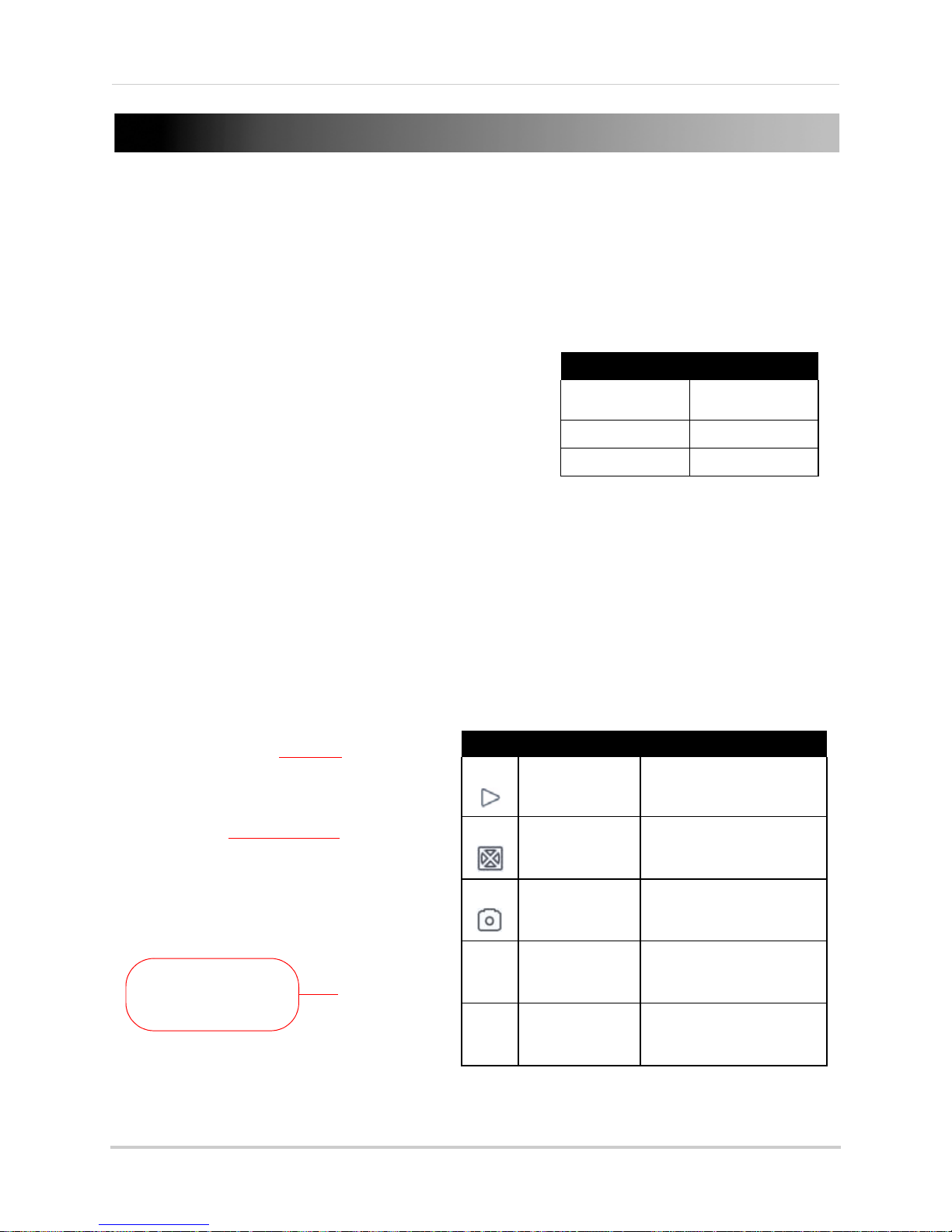
APPENDIX M:
System Requirements
Supported Devices iPhone, iPod Touch
with OS 2.2 or later
Storage Space >800KB
Optional Software iTunes
Main window
DVR IP address
DVR Channels
Icon Function Description
Connect to your cameras.
Enable/disables full screen
mode.
Takes a picture of the current
channel.
Set up your DVR’s: IP address,
port number, and account
information.
View the next batch of cameras
on your system (ranges from
cameras 1~16).
Play
Full Screen
Snap Shot
Settings
Next Group
Figure 1.0 The main interface window.
MOBILE VIEWING ON YOUR IPHONE
Mobile viewing allows you to view video streams from your DVR (Digital Video Recorder) on your
mobile device, such as an iPhone. It is an easy and convenient way to view events on your DVR.
Enabling Mobile Viewing On Your iPhone
To enable mobile viewing of your DVR, you will need an
iPhone application called Meye Sun. This application can
be downloaded through the Apple App Store™ on your
iPhone. You need to create an iTunes™ account to access
the App Store.
To download the Meye Sun application using your iPhone:
1. Touch the (App Store) icon to open the App
store.
2. Touch the Search
Search button.
3. Touch the FREE butt
icon on the bottom of the screen. Search for Meye Sun and then touch the
on, then touch Install to download and install the program.
The Meye Interface
67
Page 81

Appendix M: Mobile Viewing On Your iPhone
Figure 1.2 Settings window.
Connecting To Your DVR
Once the application is installed on your phone, you can log in and access your system remotely.
Before You Start
• If you are connected to your service provider on your iPhone (ie. 3G network), you must enter
in the W
• To find the IP address of your DVR, press the ENTER button on the front panel.
• You must enable port forwarding on your DVR (Port 100).
• It is recommended to use a static IP address. If using a dynamic IP, your WAN IP may change
frequently
NOTE: You must have access to the internet on your iPhone before you can connect to your
m
ca
To connect to your cameras:
1. From your iPhone, touch the (Meye)
icon to start the program.
N IP address of your DVR in the Settings window.
A
eras.
2. Touch the (Sett
window opens (Figur
ings) button. The setting
e 1.2).
3. Under Server Info, in the Address field,
enter y
our DVR’s WAN IP address or a
DDNS* address.In the Port field, enter your
DVR’s port number (default is port 100).
4. Under Account Info, in the User ID field,
enter ad
min. In the Password field, enter
admin.
NOTE: You can only view a single channel at
a time.
b
5. Touch the Back
utton to return to the main
screen.
6. Touch the (play) icon to begin viewing.
Touch the channel numbers on the bottom
the scr
of
een to switch channels.
Uninstalling Meye From Your iPhone
To uninstall the Meye application from your iPhone:
1. From the iPhone’s main menu, touch and hold the (Meye) icon for several seconds.
Touch the X on the top l
eft corner of the icon. A window opens that says, "Deleting "MEye" will also
delete all of its data."
2. Touch the De
68
ete button to uninstall the program.
l
Page 82

Troubleshooting
TROUBLESHOOTING
When a malfunction occurs, it may not be serious and can be corrected easily. The following
describes the most common problems and solutions. Please refer to the following before calling
Lorex Technical Support:
Error Possible Causes Solutions
• System is not
re
ceiving power, or is
not powering up
• Remote control is
no
t detected by the
system
• Hard drive is not
det
ected by the
system
• Cable from power adapter is
loose or is unplugged
• Cables are connected, but
syst
em is not receiving sufficient
power
• Battery in the remote control is
drained
• There are no batteries in the
remote control
• Hard drive cables are loose or
not properly connected
• There is no hard drive in the
syst
em
• Confirm that all cables are connected correctly
• Confirm that the power adapter is securely
co
nnected to the back of the unit
• Confirm that the system is powered on (LED
indicators on the front should be ON)
• If the unit is connected through a power bar or
sur
ge protector, try bypassing the bar and
connecting the power directly to the wall outlet
• Confirm that there is power at the outlet:
• Connecting the power cable to another outlet
• Test the outlet with another plugged device
(
uch as an electric calculator or phone
s
charger)
• Install two fresh AAA alkaline batteries in the
remote control
• Remove the housing and check that hard drive
cables are firmly connected
• Open the housing and install a 3.5" SATA hard
drive
• Hard drive is full
(0
%) and the unit is
no longer recording
• Overwrite is not enabled • From the Main Menu, select
HDD
>Overwrite>Enable and click Apply
69
Page 83

Troubleshooting
Troubleshooting (cont’d.)
Error Possible Causes Solutions
• Mouse not detected
by system
• There is no picture
on selected channels
/ camera picture is
not being displayed
• The image on the
DVR appears, but
does not have sound
• A "whirring" noise
is coming from the
system
• Mouse cable is not firmly
connected to the system
• Mouse is not connected to the
system
• System needs to be reset • Power off the system (disconnect power cable).
• Camera cables are loose or
have become disconnected
• Audio cables are loose or have
been disconnected
• Audio channels are disabled in
the system menu
• Volume on external speakers
(not included) is low or off
• Fan is active • The noise means the exhaust fan is working
• Firmly connect the mouse cable to the USB Mouse
port on the front panel
Firmly connect a USB mouse to the USB Mouse port
on the front panel of the system. Reconnect the
power cable to the DC 19V port on the rear panel.
• Check the camera video cable and connections
• Disconnect and reconnect the cable at the system
and at the camera
• Try moving the camera to another channel or use
another cable
• Check the AUDIO connections to the DVR
• Check the Configurations: Main
>Record>Audio
Menu
• Increase volume on external speakers (not
included)
normally.
• The system beeps
at startup
• The system beeps
during motion
detection
• I am not receiving
email notifications
70
• The beep at startup is normal
• Motion detection is enabled, but
the alarm buzzer is activated
• Email notification is disabled • Open Main Menu
• Default setting is disabled, but
you have not entered your own
SMTP information
• Open the Main Menu and click ADVANCE
• Click ALARM; set the Buzzer to 0s and click
APPLY
SETUP; under EMAIL select ON
• If you want to use your own SMTP server, deselect
the Default box, and enter your SMTP Server
address, Port, User name, and Password in the
respective fields
>Advance>Alarm; click EMAIL
Page 84
instructions de retour
vous au sujet des lois et règlements municipaux, provinciaux ou fédéraux qui s’appliquent à l’installation d’appareils de
surveillance audio et vidéo. Il se peut que le consentement de la partie surveillée soit exigé.
Soyez toujours très discret lorsque vous installez des systèmes de surveillance, surtout dans les endroits plus retirés. Informez-
étapes-ci :
a. Veuillez contacter notre département de service à la clientèle pour obtenir un numéro
d'autorisation pour le retour.
b. Retournez le pr oduit à : Lorex Custom er Service
300 Alden Road, Markham, ON L3R 4C1
COMPOSEZ LA LIGNE D’ASSISTANCE SANS FRAIS AUS CONOMMATEURS:
2. i) Si l'appareil a été acheté aux États-Unis
a. Veuillez contacter notre département de service à la clientèle pour obtenir un numéro
d'autorisation pour le retour.
b. Retournez le produit à : Lorex Customer Service
ii) Si l'appareil a été ac heté au Can ad a
preuve d'achat, Lorex ne sera pas dans l'obligation de remplir ses obligations envers l'acheteur. Si vous retournez
le produit et/ou le disque CD-ROM à Lorex, vous devez assumer le risque que ceux-ci soient endommagés ou
perdus au cours de l'expédition. Vous devez emballer le produit da ns sa bo îte orig inale ou un emba llage adéq uat
et vous devez défr ay er les coûts d'expédit ion à l'une des adres ses mentionnées ci-dess o us .
Pour bénéficier du se r vi c e s o us garantie, vous devez suivre les étapes ci- d es sous :
1. Emballez le produit dans une boîte solide et remplie de matériau d'expédition.
ces restrictions ne s'appliquent pas à vous. Cette garantie donne à l’acheteur original des droits spécifiques et il se
peut que d’autres droits, variant d’un état ou d’une province à l’autre, puissent lui être conférés. Obtention du service
Si l'acheteur a besoin de service pour son produit, selon les termes de cette garantie limitée, il doit fournir à Lorex
une copie de la facture d'achat affichant clairement la date et l'endroit où le produit a été acheté. Sans cette
moins que cela ne soit indique. Lorex ne sera pas tenue responsable des caractéristiques ni des fonctions du
matériel ou des logiciels d'un tiers pouvant entrer en conflit avec le fonctionnement du logiciel ci-inclus. Toutes les garanties tacites ou explicites se limitent à la durée de la ga rantie limitée. Aucune garantie ne se ra
applicable après cette période de te mp s. Certains états ou provinces ne permettent pas de restrictions en ce qui a
trait aux termes d’une garantie tacite, ni d’exclusions aux dommages-intérêts directs ou indirects et il se peut que
reproduction d'un programme ou des données stockées dans un système contenant le disque CD-ROM du produit
ou le logiciel qui accomp agne cel ui -c i.
L'acheteur peut bénéficier de certains droits provinc iaux ou fé dér aux ad ditionne ls et tout e clau se de cett e garan tie
qui soit prohibée par de tel les loi s sera jugé e nul le et sans effe t mai s les autr es cla uses dem eurer on t en vi gueu r. Lorex ne garantit pas que ce logiciel fonctionnera conjointement avec tout autre logiciel ou suite logicielle, ˆ
une réparation, un remplacement ou u n remboursement, selon les clauses décrite s dans les présentes. Ces
recours constituen t les seu ls auxq uels a droi t l'a ch eteu r pour les bris des cl aus es de la g arant ie . Lorex ne se ra pas
responsable des dommages-intérêts spéciaux, directs ou indirects, qui résulteraient d'un bris des clauses de cette
garantie ou de toute autre convention législative, incluant mais ne s'y li mitant pas, le s pertes de profits , pannes de
courant immobilisant des équipements, la valeur ajoutée des biens incorporels, les dommages effectués au produit
et à la propriété ou les coûts reliés à leur remplacement, ainsi que les frais de recouvrement, reprogrammation ou
prévenir, réduire ou d'une façon quelconque, d 'influer sur les do mmages à la pr opriété privée ou sur les ble ssures
corporelles. Lorex ne sera pas tenue responsable des blessures corporelles, dommages à la propriété
personnelle, perte ni au vol se rapportant de près ou de loin au produit ou son usage dans un cadre ma lveillant,
qu'il soit physique ou mental. Lorex n'autorise aucunement les représentants, détaillan ts ou gross istes , à faire des
revendications ou des énoncés de la part de Lorex, tant par voie écrite que verbale et ces énon cés n'influent
d'aucune manière sur les clauses de cette garantie. La seule responsabilité de Lorex, selon les termes de cette garant ie, qu'ils soient ta cites ou explicites, se limite à
circonstances hors du contrôle de Lorex. Lorex ne garantit d’aucune manière l'appar ence exté rieure du produit , ni les pièces o u acces soires inc luant, mais
ne s'y limitant pas, le boîtier, les pièces du boîtier, les boutons, etc., ainsi que le déballage, l'installation,
l'enlèvement et la réinstallation du produit après une réparation. Lorex ne garantit pas et ne fait aucune revendicatio n en ce qui a trait au po tentiel, à la capacité ou l'eff icacité de
Cette garantie a préséance sur toutes les autres garanties tacites ou explicites, incluant la garantie en qualité
loyale et marchande et les aptitudes visant to ute autre obligat ion ou responsabilit é de la part de Lore x, et par les
présentes, Lorex n’autorise aucune personne ni entité à assumer pour elle nulle autre responsabilité en rapport
avec la vente de ce produit. Lorex ne sera p as tenue responsable, en aucune circon stance, des dommages-
intérêts directs ou indirects survenant de l'utilisation du produit ou suite au mauvais fonctionnement ou à l'absence
de fonctionnement dudit produit, ainsi que pour tout délai dans l'exécution de cette garantie suite à des
iii) Si l'unité a été achetée dans Europe veuillez visiter : www.lorexinternational.com pour les
International : 800-42-LOREX 0 (800-425-67390)
www.lorexcctv.com
L'Amérique du nord: 1-888-42-LOREX (1-888-425-6739)
Local : 905-940-5355
2375 Hadley Rd, Plainfield, IN 46168
, suivez ces
, suivez ces étapes-ci :
GARANTÍA LIMITADA DEL PRODUCTO LOREX
en ese momento del Producto o CD-ROM.
el Comprador adquiera el Producto al por menor en la condición de no haber sido usado previamente.
Repuestos y Mano de Obra: 1 año (Las piezas garantizadas no incluyen
CD-ROM o, por decisión única de Lorex, al reemplazo del Producto que Lorex encuentre defectuoso.
Las obligaciones de Lorex bajo esta garantía estarán limitadas a:
• la reparación o el reemplazo del producto por medio de hardware y/o software (a opción de Lorex).
• el reemplazo de cualquier parte garantizada que Lorex determine que está defectuosa en el Producto o
• Si a Lorex no le es posible reparar o reemplazar el Producto o el CD-ROM, se devolverá el valor vigente
Se garantizará al Comprador cualquier pieza de repuesto provista por Lorex en conexión con esta garantía por
un período igual a la parte no vencida del Período de Garantía del Producto. Exclusiones de la garantía
Esta garantía no se aplica a las bombillas, LEDs y baterías suministradas con el producto o que formen parte del
mismo.
Esta garantía quedará nula si se han usado accesorios que no son Lorex en el Producto o en relación con el
mismo o si se hace alguna modificación o reparación al Producto en algún taller que no sea un local de servicio
autorizado por Lorex. Esta garantía no se aplica a defectos o daños resultantes del uso del producto en condiciones diferentes a las
normales (incluyendo condiciones atmosféricas o de humedad normales) o por la instalación o uso del Producto
en forma distinta a seguir estrictamente las instrucciones contenidas en el Manual del Propietario del Producto. Exclusiones de la garantía
Esta garantía no se aplica a las bombillas, LEDs y baterías suministradas con el producto o que formen parte del
mismo.
Esta garantía quedará nula si se han usado accesorios que no son Lorex en el Producto o en relación con el
mismo o si se hace alguna modificación o reparación al Producto en algún taller que no sea un local de servicio
autorizado por Lorex. Esta garantía no se aplica a defectos o daños resultantes del uso del producto en condiciones diferentes a las
normales (incluyendo condiciones atmosféricas o de humedad normales) o por la instalación o uso del Producto
en forma distinta a seguir estrictamente las instrucciones contenidas en el Manual del Propietario del Producto. Esta garantía no se aplica a defectos o daños al Producto causados por (i) uso negligente del Producto, (ii) mal
uso, abuso, negligencia, alteración, reparación o instalación incorrecta del Producto, (iii) cortocircuitos o
corrientes eléctricas transitorias, (iv) uso por el Comprador que no está de acuerdo con la instalación del
producto, (v) uso de piezas de repuesto no suplidas por Lorex (vi) inadecuado mantenimiento del Producto, o
(vii) accidente, incendio, inundación u otros accidentes naturales. Esta garantía no cubre el rendimiento o funcionalidad de ningún software de computadora incluido en el paquete
con el Producto. Esta garantía sólo cubre defectos en el material de CD-ROM, tal como roturas o defectos en el
CD-ROM que impida que sea leído por la unidad de CD-ROM de su computadora personal. Lorex no garantiza
que el software provisto con el Producto funcione sin interrupción o que de otra forma esté libre de anomalías,
errores o “bugs”. Lorex no ofrece ninguna garantiza con respecto a algún software provisto con el equipo a
menos que específicamente se establezca de otra forma en un acuerdo de licencia que acompañe a dicho
software.
Esta garantía no cubre ningún costo relativo a la remoción o reemplazo de algún Producto, CD-ROM, o software
instalado en su computadora.
Lorex se reserva el derecho de hacer cambios en el diseño o hacer adiciones o mejoras a sus productos sin
incurrir en ninguna obligación de modificar algún producto que ya haya sido fabricado.
Lorex tratará en lo posible de proporcionar actualizaciones y arreglos a su software por medio de su página en la
red.
Esta garantía no cubre ninguna alteración ni daño a algún otro software que pueda ser instalado o pueda quedar
instalado en el sistema del usuario como resultado de la instalación del software provisto.
Esta garantía es el reemplazo de otras garantías, expresas o implícitas, y Lorex no asume ni autoriza a ninguna
persona a asumir por ella ninguna obligación en relación con la venta o servicio del producto. En ningún caso
Lorex será responsable por ningún daño o perjuicio especial o consecuente resultante del uso del Producto o de
su mal funcionamiento o incapacidad de funcionar, o por cualquier demora en la atención de esta garantía
debida a causas fuera de su control. Esta garantía no se aplicará a la apariencia o artículos accesorios incluyendo, sin estar limitado a ellos,
gabinetes, piezas de gabinetes, perillas, etc., y el desembalaje, instalación, configuración, o remoción y
reinstalación del producto después de ser reparado.
Lorex garantiza, sólo
(el “Producto”), si se usa e instala debidamente, y – si hay lugar - el CD-ROM en el que se proporciona el
software asociado, está libre de defectos de fabricación en materiales y mano de obra, sujeto a que el Producto
sea usado en condiciones normales y que sea instalado y usado estrictamente de acuerdo con las instrucciones
contenidas.
Esta garantía será para los siguientes períodos de garantía (el “Período de Garantía”), a partir de la fecha en que
al comprador original al por menor (el “Comprador”) que este artículo
bombillas, LEDs y baterías)
a. Para devoluciones por favor contacte nuestro departamento de servicio para obtener un número de
Use siempre discreción cuando instale equipo de vigilancia por video y/o audio especialmente cuando se
percibe privacidad. Consulte acerca de las regulaciones federales, estatales y /o locales aplicables a la
instalación legal de equipos de grabación o vigilancia por video y/o audio. Puede requerirse el
consentimiento de las partes.
NUMERO GRATUITO DE SERVICIO A CLIENTES:
Norteamérica: 1-888-42-LOREX (1-888-425-6739)
Internacional: 800-42-LOREX 0 (800-425-67390)
www.lorexcctv.com
Local : 905-940-5355
b. Devuelva la unidad a: Lorex Customer Service.
ii). Si la unidad fue comprada en Canadá
autorización.
iii) Si la unidad fue adquirida en Europa y desea devolver el producto por favor visite:
www.lorexinternational.com para obtener instrucciones.
300 Alden Road, Markham, Ont. L3R 4C1
proceda en la siguiente forma:
2. i). Si la unidad fue comprada en Estados Unidos
1.
a. Para devoluciones por favor contacte nuestro departamento de servicio para obtener un número de
b. Devuelva la unidad a: Lorex Customer Service
autorización
2375 Hadley Rd, Plainfield, IN 46168
proceda en la siguiente forma:
web www.lorexcctv.com en la sección de registro de garantía. Si el Producto necesitase servicio bajo esta
garantía, el Comprador debe hacer llegar a Lorex una copia del recibo o factura de compra, con su fecha
respectiva, sin lo cual Lorex no estará obligada a cumplir con ninguna de sus obligaciones bajo esta garantía. Si
devuelve el Producto y/o el CD-ROM a Lorex, debe usted asumir el riesgo de daño o pérdida durante el envío.
Debe usar el envase original o equivalente y debe pagar el flete.
Para hacer un reclamo bajo esta garantía, proceda con los siguientes pasos. 1. Empaque el Producto en una caja robusta bien acolchada.
garantía implícita, de modo que esta limitación puede no serle de aplicación. Algunos estados no permiten la
exclusión o limitación de daños y perjuicios incidentes o consecuentes, por lo que la garantía anterior puede no
serle de aplicación. Esta garantía limitada le otorga derechos legales específicos y usted puede también tener
otros derechos que varía de un estado a otro.
Cómo obtener servicio Con el fin de obtener servicio, por favor asegúrese de registrar haber registrado su producto en nuestra pagina
El comprador puede tener otros derechos de acuerdo con las leyes federales, provinciales o estatales y cuando
toda esta garantía o parte de la misma sea prohibida por dichas leyes, será considerada nula, pero el resto de la
garantía permanecerá vigente.
Todas las garantías expresadas e implícitas están limitadas en duración al período de garantía limitada. Ninguna
garantía se aplicará después de dicho período. Algunos estados no permiten limitación a la duración de una
operación del software incluido.
datos almacenados o usados con un sistema que contenga el CD-ROM del Producto o el software que lo
acompaña. Lorex no garantiza que el software operará con ningún otro software excepto con el que se indica. Lorex no
puede ser responsable de las características de hardware o software de terceras personas que puedan afectar la
La responsabilidad de Lorex según ésta o cualquier otra garantía, implícita o explícita, está limitada a la
reparación, reemplazo o reembolso, como se establece anteriormente. Estas compensaciones son el único y
exclusivo remedio por cualquier incumplimiento de garantía. Lorex no es responsable por daños y perjuicios
directos, especiales, incidentes, o consecuentes resultantes de algún incumplimiento de garantía o bajo cualquier
otra teoría legal, incluyendo pero sin estar limitada a: pérdida de utilidades, paralización, plusvalía, daños o
reemplazo de equipos y propiedad y cualquier costo de recuperar, reprogramar o reproducir cualquier programa o
Lorex no hace ninguna de cada declaración ni garantía de ninguna clase con respecto al potencial, capacidad o
eficacia del Producto para evitar, minimizar o en alguna forma afectar a los daños o lesiones personales o a la
propiedad. Lorex no es responsable por ningún daño personal, siniestro o robo relacionado con el Producto o a su
uso para cualquier daño, sea físico o mental relacionado con el mismo. Cualquier afirmación o declaración, sea
escrita o verbal, hecha por vendedores, minoristas o distribuidores en sentido contrario no es autorizada por
Lorex y no afecta esta disposición de esta garantía.
Page 85
retailers, dealers or distributors to the contrary are not authorized by Lorex, and do not affect this provision of this
Revi
sion 1.0
warranty.
physical or mental related thereto. Any and all claims or statements, whether written or verbal, by salespeople,
responsible for any personal damage, loss or theft related to the Product or to its use for any harm, whether
This warranty shall not apply to the appearance or accessory items including, but not limited to cabinets, cabinet
parts, knobs etc., and the uncrating, set up, installation or the removal and reinstallation of pro ducts after repair. Lorex does not make any claims or warranties of any kind whatsoever regarding the Product’s potential, ability or
effectiveness to prevent minimize, or in any way affect personal or property damage or injury. Lorex is not
of installing the software provided. This warr anty is in lieu of other warranties, express or implied, and Lorex
neither assumes nor authorizes any person to assume for it any other obligation or liability in correction with the
sale or service of the Product. In no event shall Lorex be liable for any special or consequential damages arising
from the use of the Product or arising from the malf unct i oning or non-functioning of the Product, or for any delay
in the performance of this warranty due to any cause beyond its control.
your computer. Lorex reserves the right to make changes in desig n or to make additions to or improvements in its products
without incurring any obligation to modify any product which has already been manufactured. Lorex will make
every effort to provide updates and fixes to its software via its website. This warranty does not cover any
alteration or damage to any other software that may be or may become resident on the users syst em as a result
with the Product. This warranty only covers defects in the CD-ROM media such as a broken or a defect i n the
CD-ROM that would prevent the CD-ROM from being read by your personal computer’s CD-ROM drive. Lorex
makes no warranty that the software provided with the Product will function without interruption or otherwise be
free of anomalies, errors or ‘Bugs’. Lorex makes no warranty with regard to any software provided with the
Product unless specifically set forth otherwise in a license agreement accompanying such software. This warranty
does not cover any costs relating to remo val or replacement of any Product, CD-ROM, or so ft ware installed on
This warranty does not apply to defects in or dama ges to the Product caused by (i) negligent use of the Product,
(ii) misuse, abuse, neglect, alteration, repair or improper installation of the Product, (iii) electrical short circuits or
transients, (iv) Purchaser usage not in accord anc e with product installation, (v) use of replacement parts not
supplied by Lorex (vi) improper Product maintenance, or (viii) accident, fire, flood or other Acts of God. This warranty does not cover the performance or functionality of any computer software included in the package
This warranty is invalidated if other than Lorex accessor ies are or have been used in or in connection with the
Product or in any modification or repair is made to the Pr oduct by other than a service depot authorized by Lorex. This warranty does not apply to defects or damages aris ing by use of the Product in other than normal (inc lu ding
normal atmospheric, moisture and humidity) conditions or by installation or use of the Product other than in strict
accordance with the instructions contained in the Product’s Owner’s Manual.
Any replacement parts furnished by Lorex in conn ect i on with this warranty shall be warranted to the Pur chaser for
a period equal to the un expired portion of Warranty Period for the Product. Warranty Exclusions
This warranty does not apply to Bulbs, LED’s and Batteries supplied with or forming part of the p roduct.
Lorex’s obligations under this warranty shall be limited to
• The repair and or replacement of the product by means of hardware and/or software (at option of Lorex);
• The replacement of any warranted parts found by Lorex to be defective in the Product or, in Lorex’s sole
discretion, the replacement of the Product found be L orex to be defective.
• If Lorex is unable to repair or replace the Product or CD-ROM, refund the then-current value of the Product.
and installed, and where applicable, the CD-ROM on which the accompanying software is provided, is free from
manufacturing defects in material and workma nship, provided the Product is used in normal conditions and is
installed and used in strict accordance with the instructio ns contained.
This warranty shall be for the following warranty periods (t he “Warranty Period”), commencing on the date the
Purchaser buys the Product at retail in an unused con dit ion. Parts and Labor: 1 year (Warranted parts do not include
LOREX PRODUCT LIMITED WARRANTY Lorex warrants, to the original retail purchaser only
(the “Purchaser”), that this item (the “Product ”) if properly used
Bulbs, LED’s and Batteries)
300 Alden Road, Markham, Ont. L3R 4C1
iii) If the unit was purchased in Europe please visit:
b. Return the unit to: Lorex Service Center.
a. Please contact our customer service department to obtain a return
Always use discretion when installing video and/or audio surveillance equipment especially
when there is perceived privacy. Inquire regarding federal, state and/or local regulations
applicable to the lawful installation of video and or audio recording or surveillance. Party
consent may be required.
ii). If the unit was purchased in Canada
authorization number.
a. Please contact our customer service department to obtain a return
authorization number.
b. Return the unit to: Lorex Service Center
postage.
To claim on this warranty, proceed with the following steps. 1 Pack the Product in a well-padded sturdy carton.
2. i). If the unit was purchased in the United States
www.lorexinternational.com for return instructions.
Product require service under this warranty, the Purchaser must provide Lorex with
a copy of his/ her original, dated bill of sale; receipt or invoice, failing which Lorex
will not perform any of its obligations under this warranty. If you return the Product
and/or CD-ROM to Lorex, you must assume the risk of damage or loss during
shipment. You must use the original packaging or the equivalent, and you must pay
on-line (www.lorexcctv.com) in the warranty registration section.
states do not allow the exclusion or limitation of incidental or consequential
damages, so the above warranty may not apply to you. This limited warranty gives
you specific legal rights and you may also have other rights that vary from state to
state. Obtaining Service In order to obtain service, please make sure that you have registered your product
shall be deemed null and void, but the remainder of the warranty shall remain in
effect.
All expressed and implied warranties are limited in duration to the limited warranty
period. No warranties apply after that period. Some states do not allow limitation on
how long an implied warranty lasts, so this limitation may not apply to you. Some
that which is indicated. Lorex cannot be responsible for characteristics of third party
hardware or software which may effect the operation of the software included. The purchaser may have other rights under state, provincial, or federal laws and
where the whole or part of any item of this warranty is prohibited by such laws, it
downtime, goodwill, damage to or replacement of equipment and property and any
costs of recovering, reprogramming or reproducing any program or data stored in or
used with a system containing the Product CD-ROM or accompanying software. Lorex does not warrant that the software will operate with any other software except
Lorex’s responsibility under this, or any other warranty, implied or expressed, is
limited to repair, replacement or refund, as set forth above. These remedies are the
sole and exclusive remedies for any breach of warranty. Lorex is not responsible for
direct, special, incidental, or consequential damages resulting from any breach of
warranty or under any other legal theory including but not limited to, loss profits,
www.strategicvista.com
TOLL FREE CUSTOMER SUPPORT
Local: 905-940-5355
www.lorexcctv.com
2375 Hadley Rd, Plainfield, IN 46168
North America: 1-888-42-LOREX (1-888-425-6739)
International: 800-42-LOREX 0 (800-425-67390)
proceed as follows:
proceed as follows:
Should the
Les obligations de Lorex selon les termes de cette garantie se limitent exclusivement aux points
suivants :
• Lor ex se réserve le droit de réparer ou de remplacer, sa seule discrétion, le logiciel et/ou le
• Le remplacement des pièces sous garantie que Lorex estime être défect ueuses dan s le
• Si Lorex ne peut réparer ni remplacer le produit ou le disque CD -ROM , rembourser la valeur
Toutes les pièces remplacées par Lorex seront couvertes pendant la p éri od e résiduelle de la
garantie dudit produit. Exclusions de la garantie
Pour obtenir du service, veuillez vous assurer que vous avez inscrit votre produit en ligne
(www.lorexcctv.com) dans la section d'abonnement à la garantie. Cette garantie ne couvre pas
les ampoules, voyants à DEL ni les piles incluses avec le produit ou faisant partie de celui-ci.
Cette garantie deviendra nulle si des accessoires autres que ceux v endus o u distrib ués par Lor ex
sont utilisés ou ont été utilisés conjointement avec le produit ou si des modifications ou des
réparations ont été effectuées au produit par une entité autre qu'un centre de service au torisé par
Lorex. Cette garantie ne s'applique pas aux défauts ni aux dommage s surve nus suite à une uti lisation
anormale du produit (incluant des conditions atmosphériques et des taux d'hu midité an ormaux) ou
suite à une installation ou une utilisation du produit autre que celle décrite dans le guide
accompagnant le produit. Cette garantie ne s'applique pas aux défauts ni aux dommage s caus és au pro duit su ite à (i) une
utilisation insouciante du produit, (ii) mauvaise utilisation, abus, négligence, modification ou
mauvaise installation du produit, (iii) court-circuits ou transitoires électriques, (iv) tout usage de
l'acheteur qui ne correspond pas à l'installation prescrite du produit, (v) l'u ti lisation d e pièces non
fournies par Lorex, (vi) un entretien inadéquat du produit, ou (vii) tout accident, incendie, inondation
ou autres désastres naturels. Cette garantie ne couvre pas la performance ni la fonctionnalité de tout logici el informa tique inclus
avec le produit. Cette garantie ne couvre pas les défauts que pourrait contenir le suppor t optique
(disque CD-ROM) ou magnétique (disquette), tel qu'un CD-ROM brisé ou comportant un défau t qui
l'empêcherait d'être lu adéquatement par le lecteur de disque de votre ordinateur. Lorex ne garantit
pas que le logiciel fourni avec le produit fonctionnera sans interruption ni qu'il sera libre de tout
défaut, d'erreurs ou de 'bogues'. Lorex ne garantit pas le logiciel inclus à moins que c ela ne le soit
mentionné spécifiquement dans l'enten te de la licence incluse avec le prod uit. Ce tte garantie ne
couvre pas les frais se rapportant à l'enlèvement ni à la réinsertion de tout produit, logiciel,
périphérique ou disque CD-ROM ins t allé sur votre ordinateur. Lorex se réserve le droit de modifie r la conception ou d'apporter des ajouts ou des améliorations à
ses produits, sans obligation de sa part de modifier les produits déjà fabriqués. Lorex fera tout en
son pouvoir pour fournir des améliorations et des réparations à son logiciel via son site web.
Cette garantie ne couvre pas les altérations ni les dommages effectues tout autre logiciel, ni les
bogues pouvant résider de faon permanente sur le système de l'utilisateur suite l'installation du
logiciel ci-inclus.
matériel.
produit ou le disque CD-ROM ou, à sa seule discrétion, le remplacement du produit jugé
défectueux.
monétaire du produit ou du disque CD-ROM en cours au moment de l'achat.
Pièces et main-d'oeuvre : 1 année (les pièces couvertes n'inclue nt
magasin au détail.
main-d'oeuvre, pourvu que le produit soit utilisé dans des conditions normales et installé et utilisé
strictement selon les instructions inc luses dans le guide qui l'accompagne.
Cette garantie couvrira la période mentionnée ci-desso us (ci-a près désigné e comme étant la
"période de garantie"), commençant le jou r où l'acheteur se procure le produit à l'état neuf dans un
ROM qui comporte le logiciel, seront libres de tout défaut de fabrication, tant dans les pièces que la
GARANTIE LIMITÉE DES PRODUITS LOREX
Lorex garantit à l'acheteur original (ci-après désigné comme étant "l'acheteur") dans un magasin au
détail seulement
correctement et - s’il y a lieu - utilisé conformément aux instructions ci-incluses, et le disque CD-
, et que ce produit (ci-après désigné comme étant le "produit"), s'il est installé
pas les ampoules, voyants à DEL ni les
piles).
Page 86

SEE HEAR PROTECT
Enhance your security with genuine Lorex Cameras, Digital Video Recorders,
Integrated Systems and Accessories. Order whatever you need at
www.lorexcctv.com or call 1-888-42-LOREX (1-888-425-6739)
Day Care
LW2602
Warehouse
CVC6998HR
Drive Way
Office
CVC6993R
Restaurant
VQ1536HR
Convenience Store
CNC1020
PROTECT EVERYTHING
THAT MATTERS
Add wired or wireless cameras to expand the
“Envelope of Protection” for your business,
your home and your family
Front Door
Nursery
Home Office
LW2002B
Backyard
SG7555
LW1010
LW2002W
LW2201
 Loading...