

Page 1
Page 2
Thank you for purchasing this product. Digimerge is committed to providing our
customers with a high quality, reliable security solution.
This manual refers to the following models:
• DH200+ Series
For more information on this product, firmware updates, and accessory products, please
visit us at:
www.digimerge.com
CAUTION
RISK OF ELECTRIC SHOCK
DO NOT OPEN
CAUTION: TO REDUCE THE RISK OF ELECTRIC SHOCK DO NOT
REMOVE COVER. NO USER SERVICABLE PARTS INSIDE.
REFER SERVICING TO QUALIFIED SERVICE PERSONNEL.
The lightning flash with arrowhead symbol, within an equilateral
triangle, is intended to alert the user to the presence of uninsulated
"dangerous voltage" within the products ' enclosure that may be of
sufficient magnitude to constitute a risk of electric shock.
The exclamation point within an equilateral triangle is intended to
alert the user to the presence of important operating and
maintenance (servicing) instructions in the literature accompanying
the appliance.
WARNING: TO PREVENT FIRE OR SHOCK HAZARD, DO NOT
EXPOSE THIS UNIT TO RAIN OR MOISTURE.
CAUTION: TO PREVENT ELECTRIC SHOCK, MATCH WIDE BLADE
OF THE PLUG TO THE WIDE SLOT AND FULLY INSERT.
Page 3
Important Safeguards
In addition to the careful attention devoted to quality standards in the manufacturing process of
your video product, safety is a major factor in the design of every instrument. However, safety is
your responsibility too. This sheet lists important information that will help to assure your
enjoyment and proper use of the video product and accessory equipment. Please read them
carefully before operating and using your video product.
Installation
1. Read and Follow Instructions - All the safety and
operating instructions should be read before the
video product is operated. Follow all operating
instructions.
2. Retain Instructions - The safety and operating
instructions should be retained for future reference.
3. Heed Warnings - Comply with all warnings on the
video product and in the operating instructions.
4. Polarization - Do not defeat the
safety purpose of the polarized or
grounding-type plug.
A polarized plug has two blades
with one wider than the other.
A grounding type plug has two
blades and a third grounding prong.
The wide blade or the third prong
are provided for your safety.
If the provided plug does not fit into your outlet,
consult an electrician for replacement of the
obsolete outlet.
5. Power Sources - This video product should be
operated only from the type of power source
indicated on the marking label. If you are not sure of
the type of power supply to your location, consult
your video dealer or local power company. For video
products intended to operate from battery power, or
other sources, refer to the operating instructions.
6. Overloading - Do not overload wall outlets of
extension cords as this can result in the risk of fire
or electric shock. Overloaded AC outlets, extension
cords, frayed power cords, damaged or cracked wire
insulation, and broken plugs are dangerous. They
may result in a shock or fire hazard. Periodically
examine the cord, and if its appearance indicates
damage or deteriorated insulation, have it replaced
by your service technician.
7. Power Cord Protection - Power supply cords should
be routed so that they are not likely to be walked on
or pinched by items placed upon or against them,
paying particular attention to cords at plugs,
convenience receptacles, and the point where they
exit from the video product.
8. Ventilation - Slots and openings in the case are
provided for ventilation to ensure reliable operation
of the video product and to protect it from
overheating. These openings must not be blocked or
covered. The openings should never be blocked by
placing the video equipment on a bed, sofa, rug, or
other similar surface. This video product should
never be placed near or over a radiator or heat
register. This video product should not be placed in a
built-in installation such as a bookcase or rack
unless proper ventilation is provided or the video
product manufacturer’s instructions have been
followed.
9. Attachments - Do not use attachments unless
recommended by the video product manufacturer as
they may cause a hazard.
10. Camera Extension Cables – Check the rating of
your extension cable(s) to verify compliance with
your local authority regulations prior to installation.
11. Water and Moisture - Do not use this video product
near water. For example, near a bath tub, wash
bowl, kitchen sink or laundry tub, in a wet
basement, near a swimming pool and the like.
Caution
operated equipment or accessories connected to
this unit should bear the UL listing mark of CSA
certification mark on the accessory itself and should
not be modified so as to defeat the safety features.
This will help avoid any potential hazard from
electrical shock or fire. If in doubt, contact qualified
service personnel.
12. Accessories - Do not place this
video equipment on an unstable
cart, stand, tripod, or table. The
video equipment may fall, causing
serious damage to the video
product. Use this video product
only with a cart, stand, tripod,
bracket, or table recommended by the
manufacturer or sold with the video product. Any
mounting of the product should follow the
manufacturer’s instructions and use a mounting
accessory recommended by the manufacturer.
: Maintain electrical safety. Powerline
iii
Page 4

Service
13. Servicing - Do not attempt to service this video
equipment yourself as opening or removing covers
may expose you to dangerous voltage or other
hazards. Refer all servicing to qualified service
personnel.
14. Conditions Requiring Service - Unplug this video
product from the wall outlet and refer servicing to
qualified service personnel under the following
conditions:
• When the power supply cord or plug is damaged.
• If liquid has been spilled or objects have fallen into
the video product.
• If the video product has been exposed to rain or
water.
• If the video product does not operate normally by
following the operating instructions. Adjust only
those controls that are covered by the operating
instructions. Improper adjustment of other controls
may result in damage and will often require
extensive work by a qualified technician to restore
the video product to its normal operation.
• If the video product has been dropped or the cabinet
has been damaged.
• When the video product exhibits a distinct change
in performance. This indicates a need for service.
Use
19. Cleaning - Unplug the video product from the wall
outlet before cleaning. Do not use liquid cleaners or
aerosol cleaners. Use a damp cloth for cleaning.
20. Product and Cart Combination - Video and cart
combination should be moved with care. Quick
stops, excessive force, and uneven surfaces may
cause the video product and car combination to
overturn.
21. Object and Liquid Entry - Never push objects for
any kind into this video product through openings as
they may touch dangerous voltage points or
“short-out” parts that could result in a fire or
electric shock. Never spill liquid of any kind on the
video product.
22. Lightning - For added protection for this video
product during a lightning storm, or when it is left
unattended and unused for long periods of time,
unplug it from the wall outlet and disconnect the
antenna or cable system. This will prevent damage
to the video product due to lightning and power line
surges.
15. Replacement Parts - When replacement parts are
required, have the service technician verify that the
replacements used have the same safety
characteristics as the original parts. Use of
replacements specified by the video product
manufacturer can prevent fire, electric shock or
other hazards.
16. Safety Check - Upon completion of any service or
repairs to this video product, ask the service
technician to perform safety checks recommended
by the manufacturer to determine that the video
product is in safe operating condition.
17. Wall or Ceiling Mounting - The cameras provided
with this system should be mounted to a wall or
ceiling only as instructed in this guide, using the
provided mounting brackets.
18. Heat - The product should be situated away from
heat sources such as radiators, heat registers,
stoves, or other products (including amplifiers) that
produce heat.
General Precautions
iv
Page 5

General Precautions
FCC CLASS A NOTICE
NOTE
This equipment has been tested and found to comply with the limits for a Class A digital device pursuant to
Part 15 of the FCC Rules. These limits are designed to provide reasonable protection against harmful
interference when the equipment is operated in a commercial environment. This equipment generates, uses,
and can radiate radio frequency energy and, if not installed and used in accordance with the manufacturer’s
instruction manual, may cause harmful interference with radio communications. Operation of this equipment
in a residential area is likely to cause harmful interference, in which case you will be required to correct the
interference at your own expense.
www.digimerge.com
1. All warnings and instructions in this manual should be followed.
2. Remove the plug from the outlet before cleaning.
water dampened cloth for cleaning.
3. Do not use this unit in humid or wet places.
4. Keep enough space around the unit for ventilation. Slots and openings in the storage cabinet
should
5. During lightning storms, or when the unit is not used for a long time, disconnect the power
suppl
not be blocked.
y, antenna, and cables to protect the unit from electrical surge.
Do not use liquid aerosol detergents. Use a
This equipment has been certified and found to comply with the limits regulated by FCC, EMC, and
LVD. There
cause interference with other appliance usage.
However, it is imperative that the user follows the
usage which may result in damage to the unit, electrical shock and fire hazard injury.
In order to improve the feature functions and quality of this product,
to change without notice from time to time.
fore, it is designated to provide reasonable protection against interference and will not
guidelines in this manual to avoid improper
the specifications are subject
v
Page 6
Features
• H.264 compression, supports D1 resolution video recording
• Security Certified Hard Disk with up to 2TB of data storage
• Backup through USB port to flash and optical drives*
• Excellent quality live and recorded video and audio
• 480fps ‘real-time’ viewing, 240fps recording (8/16 channel)
• CMS-DH application supports up to 300 DVRs, 64 channels, live-playback, E-map, full
• control, up to 8 screen display
• 3G Smart phone viewing and control with Windows Mobile™
• Fully compatible with both PC and Mac
•
Lite Touch pad control
*
*Please visit www.digimerge.com/Touch for information, firmware, and compatibility updates for
mobile viewing
vi
Page 7

TABLE OF CONTENTS
Getting Started . . . . . . . . . . . . . . . . . . . . . . . . . . . . . . . . . . . . . . . . . . . . . . . . . 1
Basic Setup . . . . . . . . . . . . . . . . . . . . . . . . . . . . . . . . . . . . . . . . . . . . . . . . . . . . 2
Front Panel . . . . . . . . . . . . . . . . . . . . . . . . . . . . . . . . . . . . . . . . . . . . . . . . . . . . 3
Rear Panel . . . . . . . . . . . . . . . . . . . . . . . . . . . . . . . . . . . . . . . . . . . . . . . . . . . . . 5
Remote Control. . . . . . . . . . . . . . . . . . . . . . . . . . . . . . . . . . . . . . . . . . . . . . . . . 6
Mouse Control. . . . . . . . . . . . . . . . . . . . . . . . . . . . . . . . . . . . . . . . . . . . . . . . . . 7
Mouse Tips . . . . . . . . . . . . . . . . . . . . . . . . . . . . . . . . . . . . . . . . . . . . . . . . . . . . . . . . . . . . . 7
Touch Panel Tips and Tricks . . . . . . . . . . . . . . . . . . . . . . . . . . . . . . . . . . . . . . . . . . . . . . . 7
Using the System . . . . . . . . . . . . . . . . . . . . . . . . . . . . . . . . . . . . . . . . . . . . . . . 8
Quick Setup . . . . . . . . . . . . . . . . . . . . . . . . . . . . . . . . . . . . . . . . . . . . . . . . . . . . . . . . . . . . . 8
Using Quick Setup . . . . . . . . . . . . . . . . . . . . . . . . . . . . . . . . . . . . . . . . . . . . . . . . . . . . . . . . . . . . . . . . . . . . . 8
Enabling/Disabling Quick Setup . . . . . . . . . . . . . . . . . . . . . . . . . . . . . . . . . . . . . . . . . . . . . . . . . . . . . . . . . 9
Password . . . . . . . . . . . . . . . . . . . . . . . . . . . . . . . . . . . . . . . . . . . . . . . . . . . . . . . . . . . . . . . 9
On-Screen Display . . . . . . . . . . . . . . . . . . . . . . . . . . . . . . . . . . . . . . . . . . . . . . . . . . . . . . 10
Using the Virtual Remote . . . . . . . . . . . . . . . . . . . . . . . . . . . . . . . . . . . . . . . . . . . . . . . . 11
Playback . . . . . . . . . . . . . . . . . . . . . . . . . . . . . . . . . . . . . . . . . . . . . . . . . . . . . . . . . . . . . . . . . . . . . . . . . . . . 12
Using the Virtual Keyboard . . . . . . . . . . . . . . . . . . . . . . . . . . . . . . . . . . . . . . . . . . . . . . . 12
Setting the Time . . . . . . . . . . . . . . . . . . . . . . . . . . . . . . . . . . . . . . . . . . . . . . . . . . . . . . . .13
Multi-Screen Display . . . . . . . . . . . . . . . . . . . . . . . . . . . . . . . . . . . . . . . . . . . . . . . . . . . . 14
Repositioning Channels . . . . . . . . . . . . . . . . . . . . . . . . . . . . . . . . . . . . . . . . . . . . . . . . . . . . . . . . . . . . . . . 14
Zoom . . . . . . . . . . . . . . . . . . . . . . . . . . . . . . . . . . . . . . . . . . . . . . . . . . . . . . . . . . . . . . . . . 15
Sequential Setup (Auto Sequence) . . . . . . . . . . . . . . . . . . . . . . . . . . . . . . . . . . . . . . . . . 15
Recording. . . . . . . . . . . . . . . . . . . . . . . . . . . . . . . . . . . . . . . . . . . . . . . . . . . . . 16
Continuous Recording . . . . . . . . . . . . . . . . . . . . . . . . . . . . . . . . . . . . . . . . . . . . . . . . . . . 16
Event Recording . . . . . . . . . . . . . . . . . . . . . . . . . . . . . . . . . . . . . . . . . . . . . . . . . . . . . . . . 16
Motion . . . . . . . . . . . . . . . . . . . . . . . . . . . . . . . . . . . . . . . . . . . . . . . . . . . . . . . . . . . . . . . . . . . . . . . . . . . . . 17
Alarm . . . . . . . . . . . . . . . . . . . . . . . . . . . . . . . . . . . . . . . . . . . . . . . . . . . . . . . . . . . . . . . . . . . . . . . . . . . . . . 18
Video Loss . . . . . . . . . . . . . . . . . . . . . . . . . . . . . . . . . . . . . . . . . . . . . . . . . . . . . . . . . . . . . . . . . . . . . . . . . . 18
Setting Motion-only Recording . . . . . . . . . . . . . . . . . . . . . . . . . . . . . . . . . . . . . . . . . . . . 18
Enabling Motion-only recording . . . . . . . . . . . . . . . . . . . . . . . . . . . . . . . . . . . . . . . . . . . . . . . . . . . . . . . . 18
Setting Continuous & Motion Recording (C+M) . . . . . . . . . . . . . . . . . . . . . . . . . . . . . . . 20
Schedule Recording . . . . . . . . . . . . . . . . . . . . . . . . . . . . . . . . . . . . . . . . . . . . . . . . . . . . . 22
Recording Audio . . . . . . . . . . . . . . . . . . . . . . . . . . . . . . . . . . . . . . . . . . . . . . . . . . . . . . . .22
Playback. . . . . . . . . . . . . . . . . . . . . . . . . . . . . . . . . . . . . . . . . . . . . . . . . . . . . . 23
Search . . . . . . . . . . . . . . . . . . . . . . . . . . . . . . . . . . . . . . . . . . . . . . . . . . . . . . . 24
Using the Main Menu . . . . . . . . . . . . . . . . . . . . . . . . . . . . . . . . . . . . . . . . . . . 25
DISPLAY . . . . . . . . . . . . . . . . . . . . . . . . . . . . . . . . . . . . . . . . . . . . . . . . . . . . . . . . . . . . . . . 26
vii
Page 8

Sequential Setup . . . . . . . . . . . . . . . . . . . . . . . . . . . . . . . . . . . . . . . . . . . . . . . . . . . . . . . . . . . . . . . . . . . . . 26
Auto Sequence with Front Panel and Remote Control . . . . . . . . . . . . . . . . . . . . . . . . . . . . . . . . . . . . . . . . . . . . . .26
CAMERA . . . . . . . . . . . . . . . . . . . . . . . . . . . . . . . . . . . . . . . . . . . . . . . . . . . . . . . . . . . . . . . 27
CONFIGURING MOTION . . . . . . . . . . . . . . . . . . . . . . . . . . . . . . . . . . . . . . . . . . . . . . . . . . 27
RECORD . . . . . . . . . . . . . . . . . . . . . . . . . . . . . . . . . . . . . . . . . . . . . . . . . . . . . . . . . . . . . . . 28
SCHEDULE . . . . . . . . . . . . . . . . . . . . . . . . . . . . . . . . . . . . . . . . . . . . . . . . . . . . . . . . . . . .28
Stopping Scheduled Recording . . . . . . . . . . . . . . . . . . . . . . . . . . . . . . . . . . . . . . . . . . . . . . . . . . . . . . . . . 29
Overnight Recording . . . . . . . . . . . . . . . . . . . . . . . . . . . . . . . . . . . . . . . . . . . . . . . . . . . . . . . . . . . . . . . . . . 29
Example . . . . . . . . . . . . . . . . . . . . . . . . . . . . . . . . . . . . . . . . . . . . . . . . . . . . . . . . . . . . . . . . . . . . . . . . . . . . . . . . . . . .29
EVENT . . . . . . . . . . . . . . . . . . . . . . . . . . . . . . . . . . . . . . . . . . . . . . . . . . . . . . . . . . . . . . . . 30
DEVICE . . . . . . . . . . . . . . . . . . . . . . . . . . . . . . . . . . . . . . . . . . . . . . . . . . . . . . . . . . . . . . . . 30
NETWORK . . . . . . . . . . . . . . . . . . . . . . . . . . . . . . . . . . . . . . . . . . . . . . . . . . . . . . . . . . . . . 32
EMAIL . . . . . . . . . . . . . . . . . . . . . . . . . . . . . . . . . . . . . . . . . . . . . . . . . . . . . . . . . . . . . . . . . . . . . . . . . . . . . . 32
DDNS . . . . . . . . . . . . . . . . . . . . . . . . . . . . . . . . . . . . . . . . . . . . . . . . . . . . . . . . . . . . . . . . . . . . . . . . . . . . . . 33
MISC . . . . . . . . . . . . . . . . . . . . . . . . . . . . . . . . . . . . . . . . . . . . . . . . . . . . . . . . . . . . . . . . . . . . . . . . . . . . . . . 33
SYSTEM . . . . . . . . . . . . . . . . . . . . . . . . . . . . . . . . . . . . . . . . . . . . . . . . . . . . . . . . . . . . . . . 34
GENERAL . . . . . . . . . . . . . . . . . . . . . . . . . . . . . . . . . . . . . . . . . . . . . . . . . . . . . . . . . . . . . . . . . . . . . . . . . . . 34
TIME . . . . . . . . . . . . . . . . . . . . . . . . . . . . . . . . . . . . . . . . . . . . . . . . . . . . . . . . . . . . . . . . . . . . . . . . . . . . . . . 34
ACCOUNT . . . . . . . . . . . . . . . . . . . . . . . . . . . . . . . . . . . . . . . . . . . . . . . . . . . . . . . . . . . . . . . . . . . . . . . . . . . 34
DISK . . . . . . . . . . . . . . . . . . . . . . . . . . . . . . . . . . . . . . . . . . . . . . . . . . . . . . . . . . . . . . . . . . . . . . . . . . . . . . . 35
Formatting Disks . . . . . . . . . . . . . . . . . . . . . . . . . . . . . . . . . . . . . . . . . . . . . . . . . . . . . . . . . . . . . . . . . . . . . . . . . . . . 35
Disk Monitor . . . . . . . . . . . . . . . . . . . . . . . . . . . . . . . . . . . . . . . . . . . . . . . . . . . . . . . . . . . . . . . . . . . . . . . . . . . . . . . .35
. . . . . . . . . . . . . . . . . . . . . . . . . . . . . . . . . . . . . . . . . . . . . . . . . . . . . . . . . . . . . . . . . . . . . . . . . . . . . . . . . . . . . . . . . . . 35
Auto Delete . . . . . . . . . . . . . . . . . . . . . . . . . . . . . . . . . . . . . . . . . . . . . . . . . . . . . . . . . . . . . . . . . . . . . . . . . . . . . . . . . 35
UPDATE . . . . . . . . . . . . . . . . . . . . . . . . . . . . . . . . . . . . . . . . . . . . . . . . . . . . . . . . . . . . . . . . . . . . . . . . . . . . 36
INFO . . . . . . . . . . . . . . . . . . . . . . . . . . . . . . . . . . . . . . . . . . . . . . . . . . . . . . . . . . . . . . . . . . . . . . . . . . . . . . . 36
Backup . . . . . . . . . . . . . . . . . . . . . . . . . . . . . . . . . . . . . . . . . . . . . . . . . . . . . . . 37
USB Flash Drive . . . . . . . . . . . . . . . . . . . . . . . . . . . . . . . . . . . . . . . . . . . . . . . . . . . . . . . .37
External USB HDD . . . . . . . . . . . . . . . . . . . . . . . . . . . . . . . . . . . . . . . . . . . . . . . . . . . . . . 38
USB CD/DVD-RW . . . . . . . . . . . . . . . . . . . . . . . . . . . . . . . . . . . . . . . . . . . . . . . . . . . . . . . 38
Time Search and Backup . . . . . . . . . . . . . . . . . . . . . . . . . . . . . . . . . . . . . . . . . . . . . . . . . 39
Viewing Backup Video . . . . . . . . . . . . . . . . . . . . . . . . . . . . . . . . . . . . . . . . . . . . . . . . . . . 40
Using MCD Player . . . . . . . . . . . . . . . . . . . . . . . . . . . . . . . . . . . . . . . . . . . . . . . . . . . . . . . 41
CMS-DH Central Management Software . . . . . . . . . . . . . . . . . . . . . . . . . . . 43
System Requirements . . . . . . . . . . . . . . . . . . . . . . . . . . . . . . . . . . . . . . . . . . . . . . . . . . . 43
Prerequisites . . . . . . . . . . . . . . . . . . . . . . . . . . . . . . . . . . . . . . . . . . . . . . . . . . . . . . . . . . 43
Installing CMS-DH . . . . . . . . . . . . . . . . . . . . . . . . . . . . . . . . . . . . . . . . . . . . . . . . . . . . . . 44
Starting CMS-DH . . . . . . . . . . . . . . . . . . . . . . . . . . . . . . . . . . . . . . . . . . . . . . . . . . . . . . . 45
Adding a Virtual DVR . . . . . . . . . . . . . . . . . . . . . . . . . . . . . . . . . . . . . . . . . . . . . . . . . . . . 50
Creating New Group Folders & Sub folders . . . . . . . . . . . . . . . . . . . . . . . . . . . . . . . . . 52
Configuring General System Settings . . . . . . . . . . . . . . . . . . . . . . . . . . . . . . . . . . . . . . 53
Adding Users . . . . . . . . . . . . . . . . . . . . . . . . . . . . . . . . . . . . . . . . . . . . . . . . . . . . . . . . . . . 54
Recording Video to the hard drive . . . . . . . . . . . . . . . . . . . . . . . . . . . . . . . . . . . . . . . . . 55
Playing back recorded video . . . . . . . . . . . . . . . . . . . . . . . . . . . . . . . . . . . . . . . . . . . . . . 56
Remote Search . . . . . . . . . . . . . . . . . . . . . . . . . . . . . . . . . . . . . . . . . . . . . . . . . . . . . . . . . 57
viii
Page 9

Video Playback Controls . . . . . . . . . . . . . . . . . . . . . . . . . . . . . . . . . . . . . . . . . . . . . . . . . . . . . . . . . . . . . . . 58
Local Search . . . . . . . . . . . . . . . . . . . . . . . . . . . . . . . . . . . . . . . . . . . . . . . . . . . . . . . . . . .58
Saving Video Files . . . . . . . . . . . . . . . . . . . . . . . . . . . . . . . . . . . . . . . . . . . . . . . . . . . . . . . . . . . . . . . . . . . . 59
Converting video files to AVI . . . . . . . . . . . . . . . . . . . . . . . . . . . . . . . . . . . . . . . . . . . . . . . . . . . . . . . . . . . . 60
Schedule Recording . . . . . . . . . . . . . . . . . . . . . . . . . . . . . . . . . . . . . . . . . . . . . . . . . . . . . 61
Schedule Backup . . . . . . . . . . . . . . . . . . . . . . . . . . . . . . . . . . . . . . . . . . . . . . . . . . . . . . . 61
Taking Screen Captures . . . . . . . . . . . . . . . . . . . . . . . . . . . . . . . . . . . . . . . . . . . . . . . . .63
Viewing File Download Status . . . . . . . . . . . . . . . . . . . . . . . . . . . . . . . . . . . . . . . . . . . . . 63
Changing viewing modes . . . . . . . . . . . . . . . . . . . . . . . . . . . . . . . . . . . . . . . . . . . . . . . . . 64
E-Map Setup . . . . . . . . . . . . . . . . . . . . . . . . . . . . . . . . . . . . . . . . . . . . . . . . . . . . . . . . . . . . . . . . . . . . . . . . 66
Viewing video on E-Map . . . . . . . . . . . . . . . . . . . . . . . . . . . . . . . . . . . . . . . . . . . . . . . . . . . . . . . . . . . . . . . 67
Configuring E-Map camera settings . . . . . . . . . . . . . . . . . . . . . . . . . . . . . . . . . . . . . . . . . . . . . . . . . . . . . 67
Zooming into the E-Map . . . . . . . . . . . . . . . . . . . . . . . . . . . . . . . . . . . . . . . . . . . . . . . . . . . . . . . . . . . . . . . 68
Removing camera icon in the E-Map . . . . . . . . . . . . . . . . . . . . . . . . . . . . . . . . . . . . . . . . . . . . . . . . . . . . 68
Adding Multiple E-Maps . . . . . . . . . . . . . . . . . . . . . . . . . . . . . . . . . . . . . . . . . . . . . . . . . 68
Viewing DVR Health . . . . . . . . . . . . . . . . . . . . . . . . . . . . . . . . . . . . . . . . . . . . . . . . . . . . . 69
Closing windows . . . . . . . . . . . . . . . . . . . . . . . . . . . . . . . . . . . . . . . . . . . . . . . . . . . . . . . . 69
Locking Windows . . . . . . . . . . . . . . . . . . . . . . . . . . . . . . . . . . . . . . . . . . . . . . . . . . . . . . . 69
DVR Log . . . . . . . . . . . . . . . . . . . . . . . . . . . . . . . . . . . . . . . . . . . . . . . . . . . . . . . . . . . . . . . 70
Setting PTZ Pre-Sets . . . . . . . . . . . . . . . . . . . . . . . . . . . . . . . . . . . . . . . . . . . . . . . . . . . . . . . . . . . . . . . . . 72
Upgrading the firmware remotely (DH200+ Series only) . . . . . . . . . . . . . . . . . . . . . . . 74
Configuring Post Event Action Tab . . . . . . . . . . . . . . . . . . . . . . . . . . . . . . . . . . . . . . . . . 75
Setting up Post Event Actions on a NO/NC Device . . . . . . . . . . . . . . . . . . . . . . . . . . . . . . . . . . . . . . . . . . 75
Configuring Alarm Output . . . . . . . . . . . . . . . . . . . . . . . . . . . . . . . . . . . . . . . . . . . . . . . . 76
Setting message pop-up notifications . . . . . . . . . . . . . . . . . . . . . . . . . . . . . . . . . . . . . . . . . . . . . . . . . . . . 77
Setting Video pop-up notifications . . . . . . . . . . . . . . . . . . . . . . . . . . . . . . . . . . . . . . . . . . . . . . . . . . . . . . . 78
Configuring other Post Action Events . . . . . . . . . . . . . . . . . . . . . . . . . . . . . . . . . . . . . . 80
POS Data Search . . . . . . . . . . . . . . . . . . . . . . . . . . . . . . . . . . . . . . . . . . . . . . . . . . . . . . . . 80
Running CMS-DH on multiple monitors . . . . . . . . . . . . . . . . . . . . . . . . . . . . . . . . . . . . 81
iSMS Client (Remote Viewing on the Mac). . . . . . . . . . . . . . . . . . . . . . . . . . 82
System Requirements . . . . . . . . . . . . . . . . . . . . . . . . . . . . . . . . . . . . . . . . . . . . . . . . . . . 82
Prerequisites . . . . . . . . . . . . . . . . . . . . . . . . . . . . . . . . . . . . . . . . . . . . . . . . . . . . . . . . . . 82
Installation Steps . . . . . . . . . . . . . . . . . . . . . . . . . . . . . . . . . . . . . . . . . . . . . . . . . . . . . . .82
Using the iSMS Client . . . . . . . . . . . . . . . . . . . . . . . . . . . . . . . . . . . . . . . . . . . 83
iSMS Interface . . . . . . . . . . . . . . . . . . . . . . . . . . . . . . . . . . . . . . . . . . . . . . . . . . . . . . . . .84
Configuring OSD Settings . . . . . . . . . . . . . . . . . . . . . . . . . . . . . . . . . . . . . . . . . . . . . . . . 86
Searching for video remotely . . . . . . . . . . . . . . . . . . . . . . . . . . . . . . . . . . . . . . . . . . . . . 86
Searching for video locally . . . . . . . . . . . . . . . . . . . . . . . . . . . . . . . . . . . . . . . . . . . . . . . 89
Configuring PTZ settings . . . . . . . . . . . . . . . . . . . . . . . . . . . . . . . . . . . . . . . . . . . . . . . . . 90
Configuring PTZ Protocols in the iSMS Client . . . . . . . . . . . . . . . . . . . . . . . . . . . . . . . . 92
Configuring the iSMS Client . . . . . . . . . . . . . . . . . . . . . . . . . . . . . . . . . . . . . 93
Digi Imobile Touch - iPhone App. . . . . . . . . . . . . . . . . . . . . . . . . . . . . . . . . . 94
Digi iMobile Touch Lite - ANDROID. . . . . . . . . . . . . . . . . . . . . . . . . . . . . . . 103
ix
Page 10

Installing the BDVRViewer App on your Blackberry . . . . . . . . . . . . . . . . 108
Appendix A: System Specifications . . . . . . . . . . . . . . . . . . . . . . . . . . . . . . 112
Appendix B: Setting up Remote Viewing . . . . . . . . . . . . . . . . . . . . . . . . . . 114
Appendix C: Digimerge Auto Port Forwarding Wizard . . . . . . . . . . . . . . 117
Appendix D: Setting Up DDNS Service . . . . . . . . . . . . . . . . . . . . . . . . . . . . 124
Appendix E: Setting Up Mobile Access. . . . . . . . . . . . . . . . . . . . . . . . . . . . 127
Appendix F: Connecting PTZ Cameras. . . . . . . . . . . . . . . . . . . . . . . . . . . . 131
Appendix G: Connecting Additional External Monitors . . . . . . . . . . . . . . 135
Appendix H: Connecting Motion / Alarm Devices . . . . . . . . . . . . . . . . . . . 136
Appendix I: Full Connectivity Diagram. . . . . . . . . . . . . . . . . . . . . . . . . . . . 138
Appendix J: Replacing the Hard Drive . . . . . . . . . . . . . . . . . . . . . . . . . . . . 139
Appendix K: Using Listen-in Audio . . . . . . . . . . . . . . . . . . . . . . . . . . . . . . . 142
Appendix L: Converting Video Files to AVI . . . . . . . . . . . . . . . . . . . . . . . . 143
Appendix M: Remote Viewing using Internet Explorer . . . . . . . . . . . . . . 145
Troubleshooting . . . . . . . . . . . . . . . . . . . . . . . . . . . . . . . . . . . . . . . . . . . . . . 147
x
Page 11
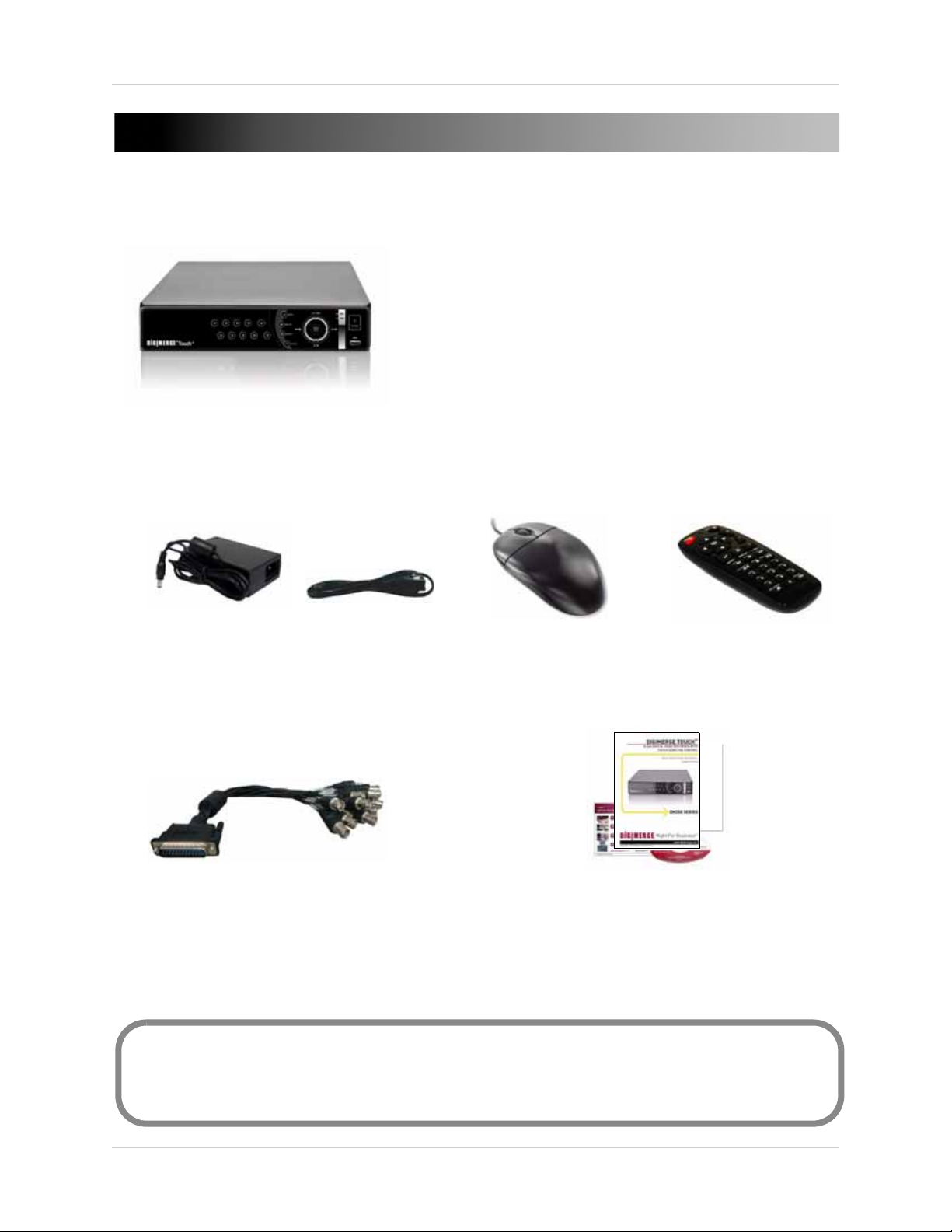
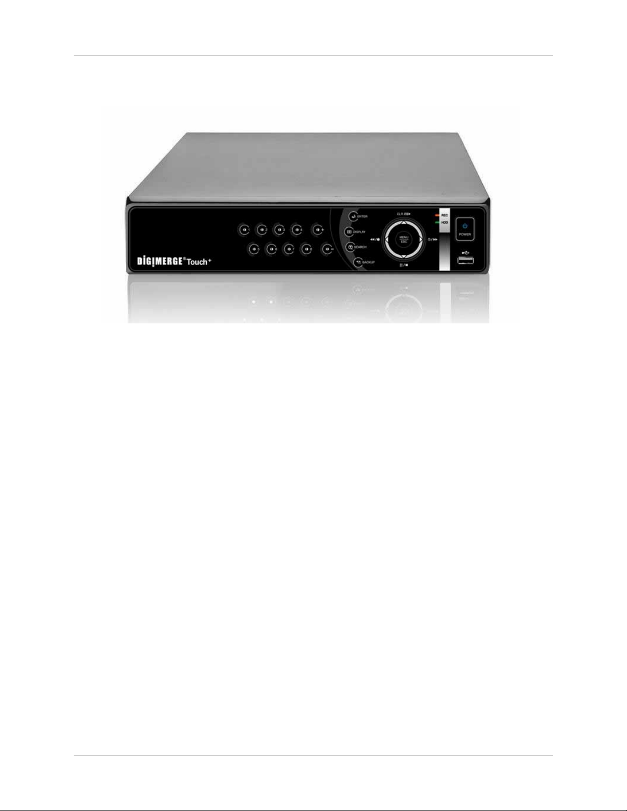
GETTING STARTED
DIGIMERGE TOUCH+ DIGITAL VIDEO RECORDER
POWER SUPPLY
INSTRUCTION MANUAL,
QUICKSTART GUIDE, &
SOFTWARE CD
REMOTE CONTROL
ETHERNET CABLE
MOUSE
OCTOPUS CABLE
[16-CHANNEL ONLY]
The system comes with the following components:
HARD DRIVE SIZE, NUMBER OF CHANNELS, AND CAMERA CONFIGURATION MAY VARY
BY MODEL. PLEASE REFER TO YOUR PACKAGE FOR SPECIFIC CONTENT DETAILS.
CHECK YOUR PACKAGE TO CONFIRM THAT YOU HAVE RECEIVED THE COMPLETE SYSTEM,
INCLUDING ALL COMPONENTS SHOWN ABOVE.
1
Page 12
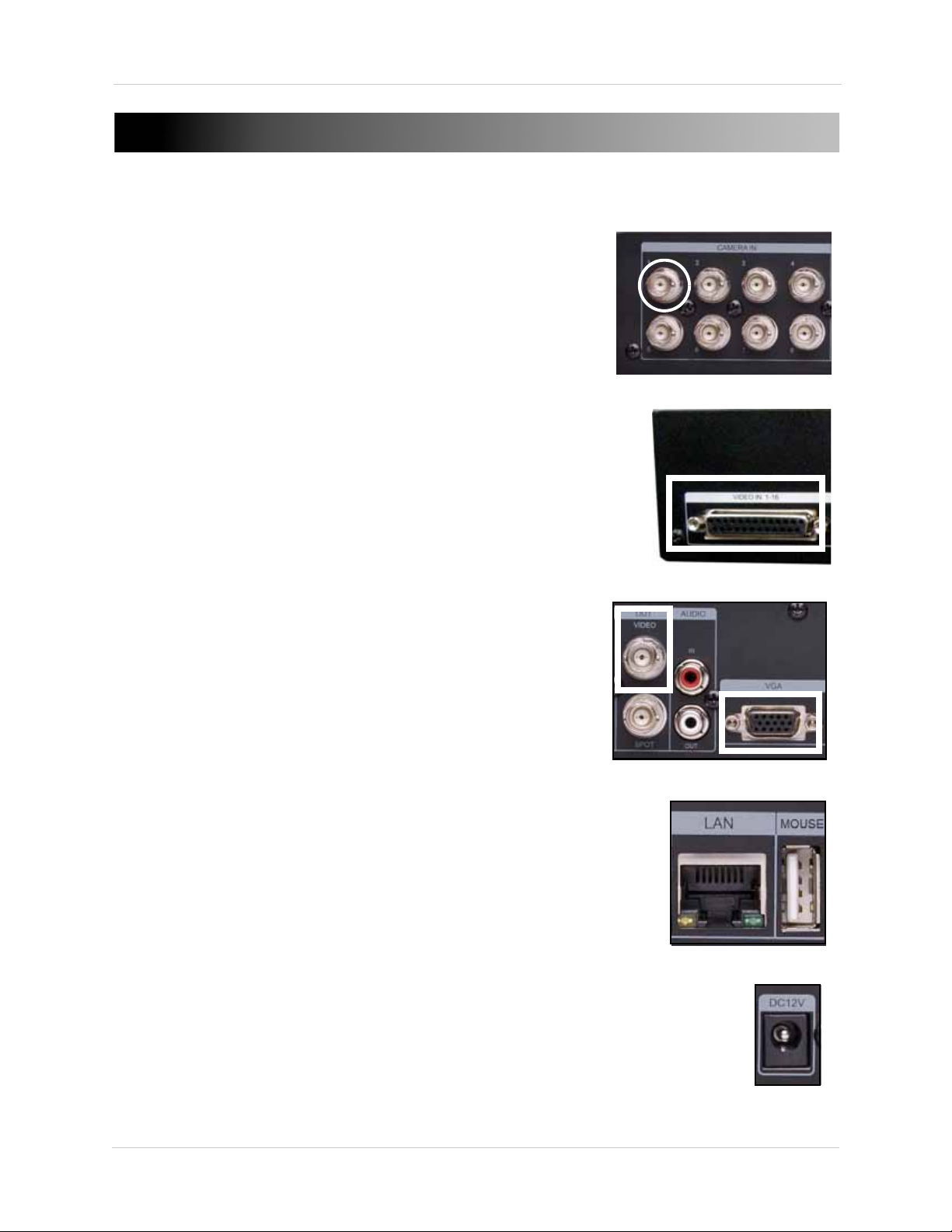
BASIC SETUP
Figure 1.0 Connect BNC cameras to the system
Fi gu re 1. 2 C on ne ct t o a VGA o r C CT V mo ni to r, o r a TV
Figure 1.3 Connect an Ethernet cable and mouse
Figure 1.4 Connect the power cable
Figure 1.1 Octopus cable port (16-channel only)
1. Connect the cameras
a. Connect BNC cameras to the BNC ports on the
rear panel (4/8-channel models).
OR
a. 16-CHANNEL MODELS ONL
end of the octopus cable to the VIDEO IN1-16 port
(see figure 1.1).
b. Connect BNC cameras to the octopus cable.
2. Connect a monitor
a. Connect a VGA cable (not included) from the VGA
port on the rear panel to the VGA port on your
monitor.
OR
a. Connect a BNC terminated cable from one of the
Video OUT por
3. Connect the mouse (USB or PS/2)
a. Connect the mouse to the USB mouse port on the
rear panel.
Y: Connect the single
ts to a TV or CCTV monitor.
NOTE: If using a PS/2 mouse, a USB adapter will
be required (not included).
4. Connect the Ethernet cable
a. Connect an Ethernet cable to the LAN port on the
rear panel of system; connect the other end of the
Ethernet cable to an empty LAN port on your
router or switch (not included).
5. Connect the power cable
a. Connect the power supply to the DC 12V port on
the rear panel of the system; connect the power
cable to an outlet, power strip, or surge protector.
2
Page 13
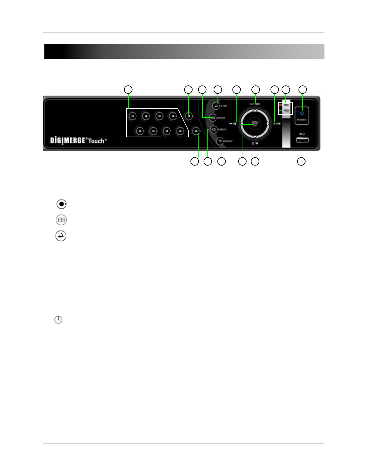
FRONT PANEL
12
1
2
3
4
5
6
7
8 9
10
11 1413
15
Figure 1.5 Front panel (8-channel model shown)
1. Channel buttons: Press to view channels individually in full-screen.
2. : Press to increase values in menu options.
3. : Press to switch between full-screen single channel, quad, and split-screen display views.
4. : Press to confirm menu options.
5.
/ : Press to perform the following:
6. CLR
7. /
8. LE
9. POW
Ds: REC will be solid red during recording; HDD will flash green when the system is accessing the
HDD.
Live viewing
•
•
Playback
•
Menu
: Press to perform the following:
Live viewing
•
•
Playback
•
Menu
: Press to perform the following:
Live viewing
•
password required for stoppage)
Playback
•
•
Menu
ER: Press to power the system ON/OFF (password required).
: Start/Stop recording (password required for stoppage)
: Increase reverse playback speed 1X, 2X, 4X, 8X, and 16X
: Move cursor left
: Show/hide onscreen display (OSD)
: Play/pause playback
: Move cursor up
: Start/stop scheduled recording (Recording Schedule must already be configured;
: Increase forward playback 1X, 2X, 4X, 8X, and 16X
: Move cursor right
3
Page 14
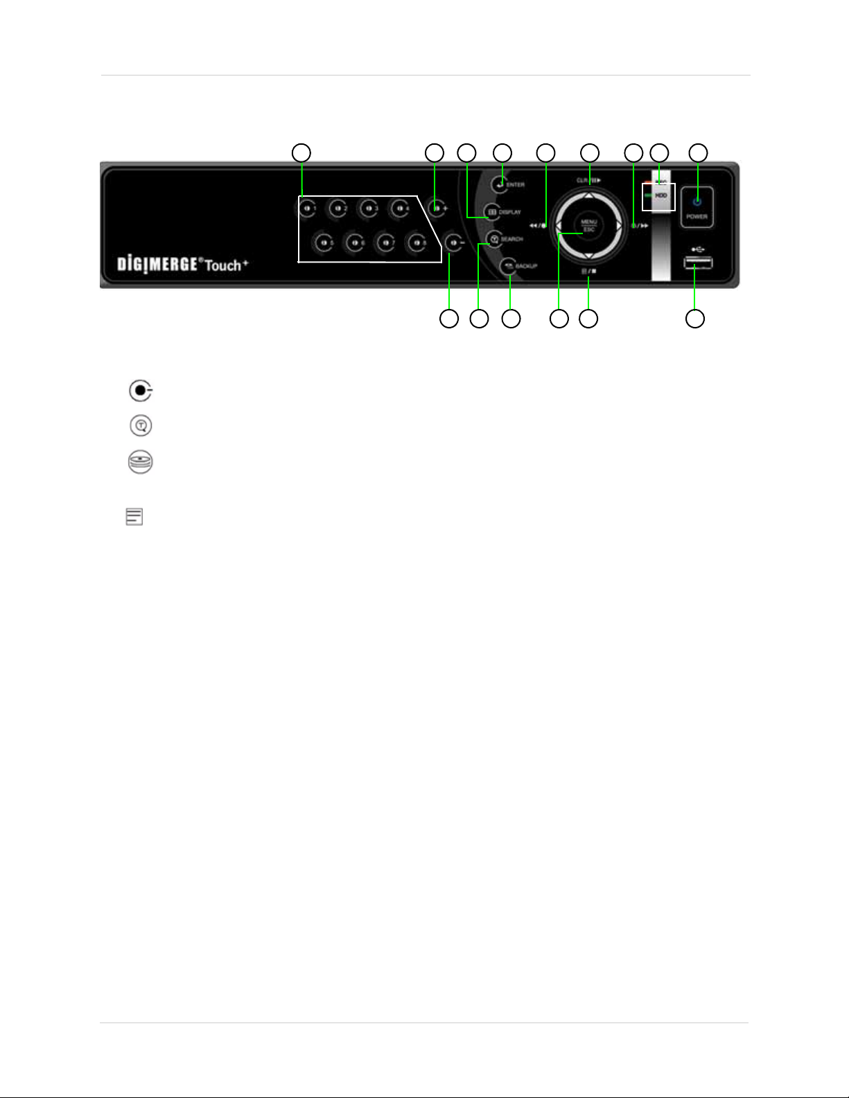
Front Panel
12
1
2
3
4
5
6
7
8 9
10
11
14
13
15
Figure 1.6 Front panel (8-channel model shown)
Front Panel (cont’d.)
10. : Press to decrease values in menu options.
11. : Press to open/close the Time Search menu.
12. : Press to open/close the Backup menu.
13. MENU/ESC:
14. /
: Press to perform the following:
15. USB P
Press to open/close the Main Menu; press to close menu windows.
Live viewing
•
•
Playback
•
Menu
: Open the Log menu
: Stop playback
: Move cursor down
ort: Connect a USB flash drive, HDD, or optical drive for critical data backup; connect a USB
flash drive for firmware upgrades
4
Page 15
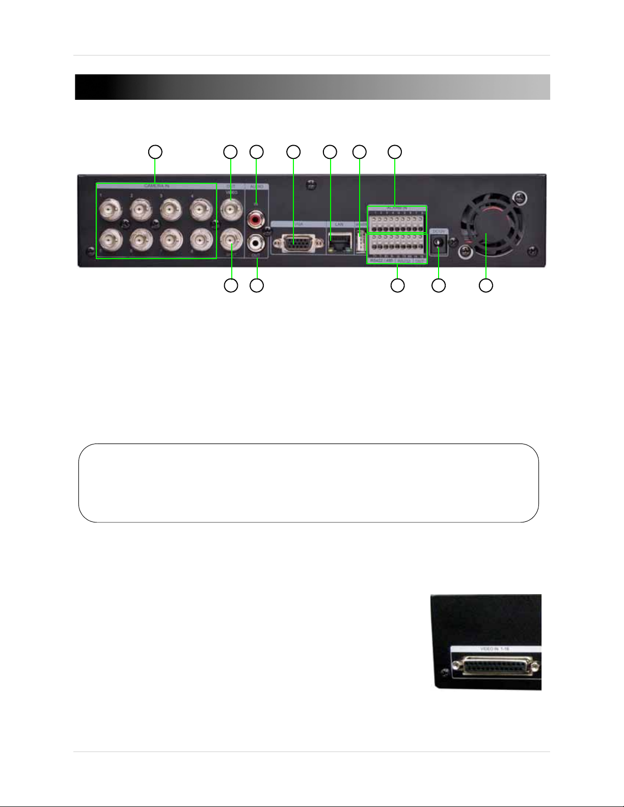
REAR PANEL
4
5
6
7
1 2
3
8 9 10 11 12
Figure 1.7 Rear panel (8-channel model shown)
NOTE: On the 4-channel DH200+ models, the rear USB port is used for the mouse only.
Do not connect a USB flash drive / external DVD writer to the rear USB port.
NOTE: On the 4-channel DH200+ models, you must use a PS/2 compatible USB mouse
(included). A regular USB 2.0 mouse will not work on the rear panel USB port.
Figure 1.8 Octopus cable VIDEO IN (16-channel only)
1. CAMERA IN: Camera input ports for BNC cameras (4/8-channel);
VIDEO IN 1-16: Port for octopus cable (16-channel models only—see figure 1.8)
2. VIDEO OUT:
3. AUDIO IN:
4. VGA:
5. LAN:
6. MOUSE: USB
VGA port to connect the system to a VGA monitor.
Connect an Ethernet cable to connect the system to a router or switch (not included).
Video output (BNC) to connect the system to a secondary monitor or DVR.
One 3.5" RCA port (mono) for recording audio from an audio capable camera (not included).
port to connect a USB or PS/2 mouse (PS/2 mouse requires USB adapter).
7. ALARM IN:
8. SP
9. AUDIO OUT:
10. RS422
11. DC 12V:
12. Ex
OT OUT: Video output to connect the system to an external monitor (not included). Spot Out mode
only displays channels switching in an automatic sequence.
camera (not included).
NOTE: The RS232 ports ar
A PTZ camera cannot be controlled from these ports.
haust fan: Do not block. Keep clear to allow for proper
ventilation.
Alarm block to connect external alarm or motion devices (not included).
One 3.5" RCA port (mono) for audio output.
/ 485 / OUT: Connection block for an RS422/485 PTZ
Port for 12V DC 3A power supply (included).
e for development purposes only.
5
Page 16
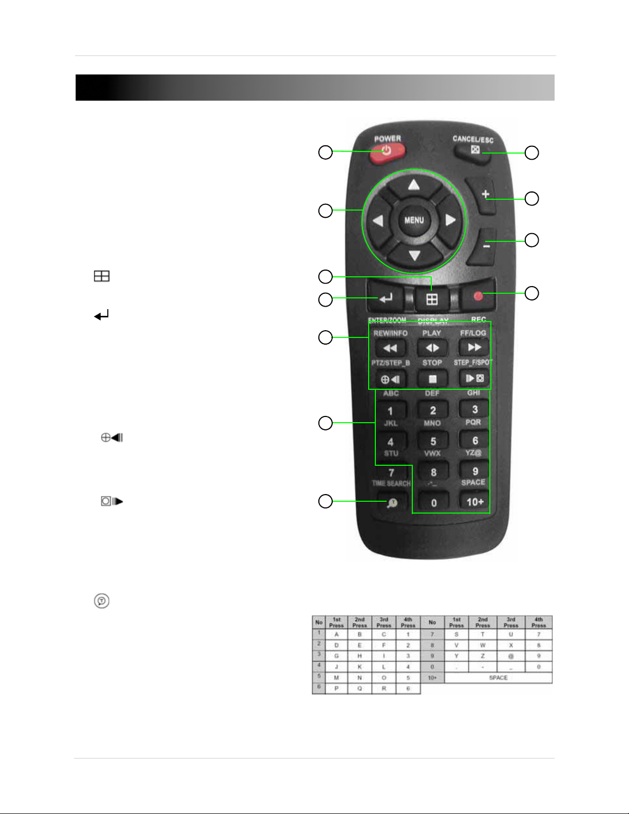
REMOTE CONTROL
8
9
3
2
4
5
6
7
10
11
You can use the channel buttons on the remote
control to enter numbers, letters, and other
characters.
1
1 POWER: Press to power the system ON/OFF
(password required).
2. Navigation/Menu:
S: Press to move cursor up
•
• T: Press to move cursor down
• W: Press to move cursor left
• X: Press to move cursor right
NU: Press to open the Main Menu
• ME
3. : Press to switch between single channel
full-screen, quad, and split-screen displays.
4.
5. Playb
: Press to confirm menu options/selections.
ack controls:
: Press to increase reverse playback speed 1X,
•
2X, 4X, 8X, and 16X.
• WX: Press to begin playback; press to switch
between forward and reverse playback
• : Press to increase forward playback speed 1X,
2X, 4X, 8X, and 16X
• : During playback, press to pause; press
repeatedly for frame-by-frame playback; during
ive viewing, press to open the PTZ menu
l
: Press to stop playback
•
• : During playback, press to pause; press
repeatedly for frame-by-frame playback; during
live viewing
6. Channel butt
individually in full-screen; press to input passwords;
when entering camera titles, press for
alpha-numeric characters.
7.
8. C
9.
10.
: Press to open the Time Search menu.
ANCEL/ESC: Press to close menu windows; press
to show/hide the on-screen display (OSD); press to
clear channel indicators (loss, alarm, etc.).
+: Press to increase values in menu options.
- : Press to decrease menu options in menu options.
, press to Spot Out.
ons: Press to view channels 1~8
z: Press to start/stop manual recording.
11.
6
Page 17
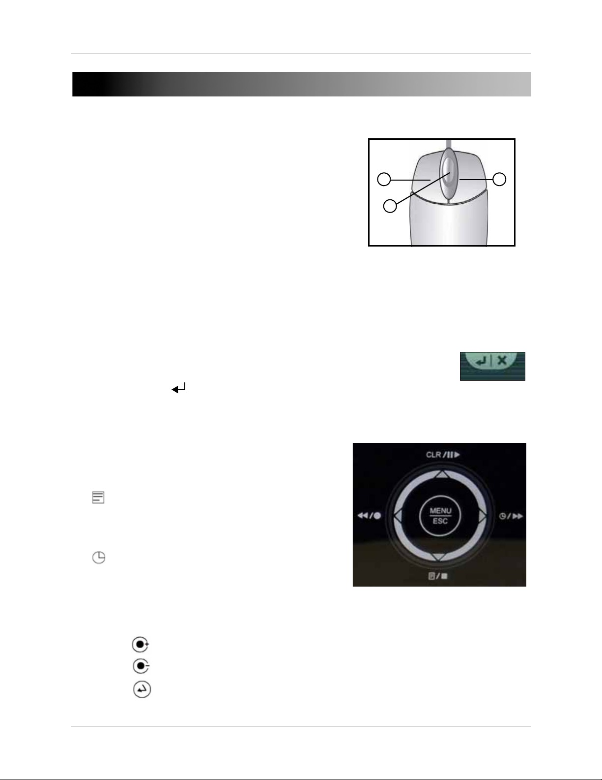
MOUSE CONTROL
1 2
3
The mouse is the primary control device for the system. To
connect a USB mouse:
• Connect a USB / PS/2 mouse to the USB port on the rear panel—
NOT
connect the mouse to the USB port on the front panel. The USB
port on the front panel is strictly intended for data transfer.
1. Left-Button: While in a split-screen display mode,
double-click an individual channel to view it in full-screen;
double-click again to return to the split-screen display mode.
While navigating menus, click to select a menu option;
double-click to open the next menu.
2. Right
3. Scr
-Button: Right-click anywhere on the screen to open the Virtual Remote; double-click anywhere
on the screen to return to the previous menu.
oll-Wheel: Move the scroll wheel up or down to increase/decrease the value of a selected menu
option.
Mouse Tips
When using the mouse, the ENTER and EXIT buttons appear in the top-right
corner of every menu window. When you change system settings and
configurations, click to confirm your changes.
DO
Touch Panel Tips and Tricks
If using the Touch panel, you will often use the following
buttons when controlling the system:
• CLR:
viewing
• /:
viewing
• / :
playback speed;
• /:
playback speed;
• Press the MENU/ESC button to open the main menu AND close
windows/exit
NOTE: This manual refers to the CANCEL/ESC button on the remote control for closing/exiting menu windows. If
using the front panel, press MENU/ESC to close/exit menu windows.
• Press the button to increase values for selected menu options
• Press the button to decrease values for selected menu options
• Press the button to enter/confirm.
Menus
: show/hide OSD; clear channel icons
Menus
: open Log menu
Menus
Menus
: move cursor up;
: move cursor down;
: move cursor left;
Live viewing
: move cursor right;
Live viewing
: start/stop recording
: start/stop scheduled recording
Playback
Playback
Playback
Playback
: pause playback;
: stop playback;
: increase reverse
: increase forward
Live
Live
7
Page 18
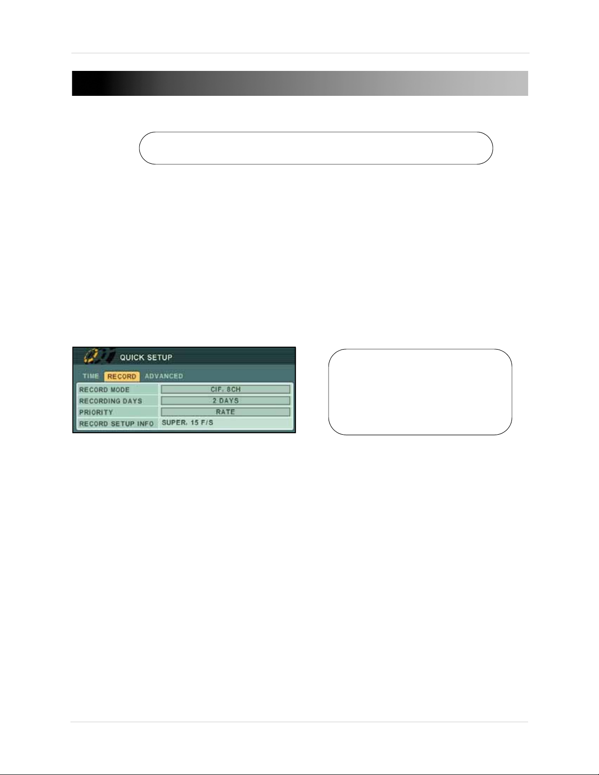
USING THE SYSTEM
The default system password is 000000
Figure 2.0 Quick Setup menu
To access the Quick Setup
menu, from the Main menu,
select
Display>Quick Setup.
Then select "ON" to enable
Quick Setup.
To power the system ON/OFF:
1. Connect the power cable to the port on the rear panel.
2. Press the
POWER button on the front panel or remote control.
NOTE: You need to press the Power button for initial startup
viewing screen on subsequent resets.
NOTE: You will need to input your system password to power off the system.
only
. The system will load the live
Quick Setup
By default, the system has Quick Setup disabled. Quick Setup lets you quickly adjust the time and
record mode on the system. The system menu will appear as the Quick Setup menu with only Time
and Record options available.
Using Quick Setup
Use Quick Setup to set the time and configure basic recording settings.
To set the time:
1. Under the Time tab, select
2. Select
TIME and enter the time (hh/mm/ss).
DATE and press the ENTER button. Enter the month, day, and year.
NOTE: If using the mouse, you will enter the date and time with the Virtual Keyboard.
3. Press the
To configure recording settings:
1. Stop ALL RECORDING on the system. Enter your system password (by default, 000000).
2. Under the RECORD tab, select RECO
FIELD 4CH, FRAME 4CH, CIF 8CH, FIELD 8CH, FRAME 8CH, or CIF + FRAME.
NOTE: If "CIF + FRAME" recording mode is selected, only channel 1 will record in frame—the
remaining channels will record in CIF.
3. Under the RECORD tab, select RECO
HOURS, 1~6 DAYS, 1~20 WEEKS, or NONE.
8
ENTER button to save your changes.
RD MODE and select one of the following: CIF 4CH,
RDING DAYS. Press the +/ - buttons and select 12
Page 19
Using the System
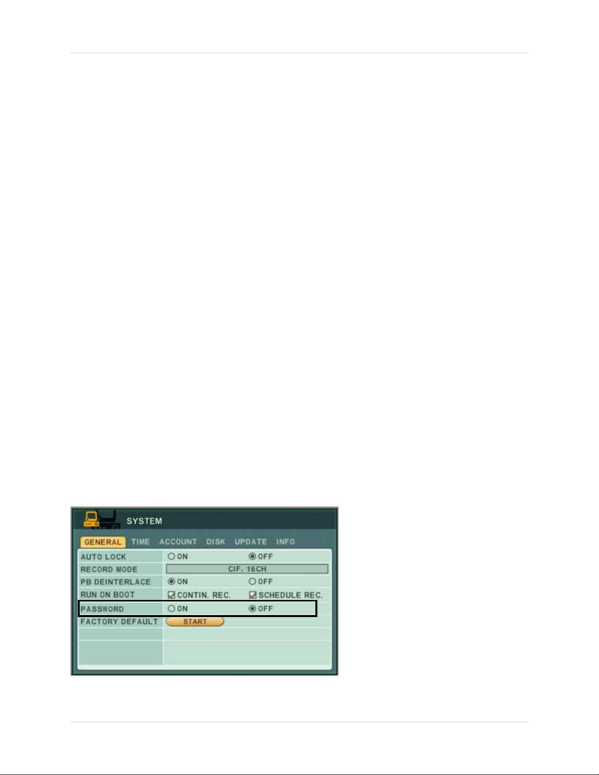
Figure 3.0 Enable password (optional)
Using Quick Setup (cont’d.)
4. Under PRIORITY, select QUALITY (the quality of the video) or RATE (frames per second). If you
select RATE, the video quality and frames per second will be at the lowest possible setting.
This will reduce overall video quality, but will maximize the available hard drive space. Adjust
this setting to best suit your recording environment and security needs. For details on
configuring recording options, see “RECORD” on page 28.
NOTE: The necessary recording parameters will appear under RECORD SETUP INFO at the
bottom of the Quick Setup window.
5. Press the
ENTER button to save your settings.
Enabling/Disabling Quick Setup
You must disable Quick Setup in order to access the full system main menu.
To disable Quick Setup:
1. Under the ADVANCED tab, select
2. Select
The full main menu will appear when you press the MENU button.
To enable Quick Setup:
1. Press the MENU
2. Select
3. Under the DISPLAY SETUP tab, move the cursor to QU
ENTER button.
4. Press the CA
Press the MENU butt
ON and press the ENTER button. The window closes. Quick Setup has been disabled.
button. The Main menu opens.
DISPLAY and press the ENTER button.
NCEL/ESC button to exit.
on again to open the Quick Setup menu.
RUN ADVANCED.
ICK SETUP, select ON and press the
Password
The default system password is 000000. However, you do not have to enter a password upon initial
startup. You can enable this option in Main Menu>System>
on page 34. For complete information on changing your password and managing users on the
system, see “ACCOUNT” on page 34.
General. For details, see “GENERAL”
9
Page 20
Using the System
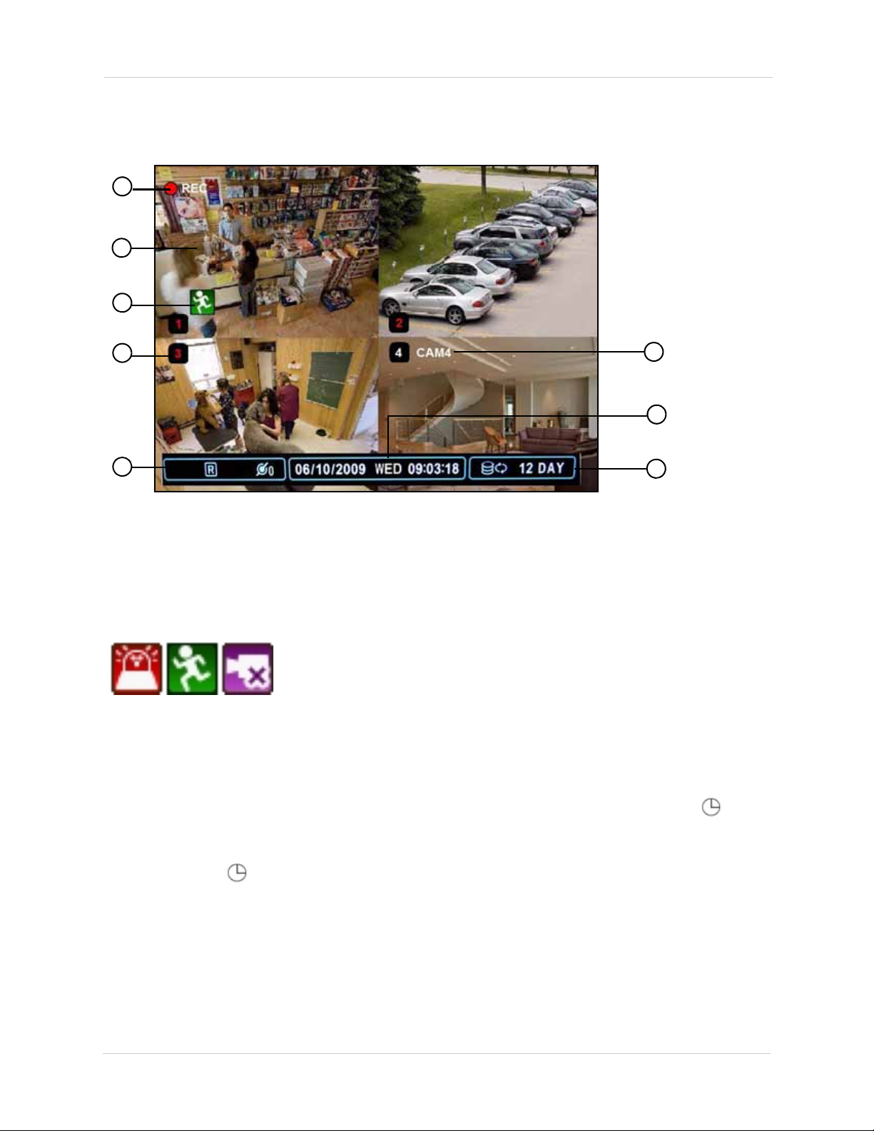
Figure 4.0 Main system display
1
2
7
8
3
4
5
6
On-Screen Display
The system shows the following for all display views:
1. Recording: "REC" indicates that continuous recording is enabled on at least one channel.
NOTE:
2. Display: Show live video and playback in single channel full-screen, quad, and split-screen configurations.
3. Camer
4. Chann
either a RED number (recording) or WHITE number (no recording).
NOTE:
If REC does not appear on the onscreen display the system is NOT RECORDING.
a Status: Will display a green Motion icon, purple Loss icon, or red Alarm icon.
el number: By default, the individual channel number appears at the bottom of the frame with
A white number may mean that a channel has been assigned motion recording. For
details, see “Recording” on page 16.
Status: Shows recording, display type, and network status. "R" indicates recording;
5.
indicates schedule recording.
NOTE: Al
RECORDING. If does not appear in the
6. Channel Title: You can customize the channel with a unique name for each channel. See
ways check for these icons. If "R" does not appear in the status bar, the system is NOT
status bar, Schedule Recording is NOT ENABLED.
“CAMERA” on page 27.
7. Date/Time: Shows the date (mm/dd/yyyy), day of the week, and time (24-hour clock).
8. HDD/Rec
remaining.
ord days: The percentage of free space remaining on the hard disk; number of recording days
10
Page 21
Using the System
2
3
1
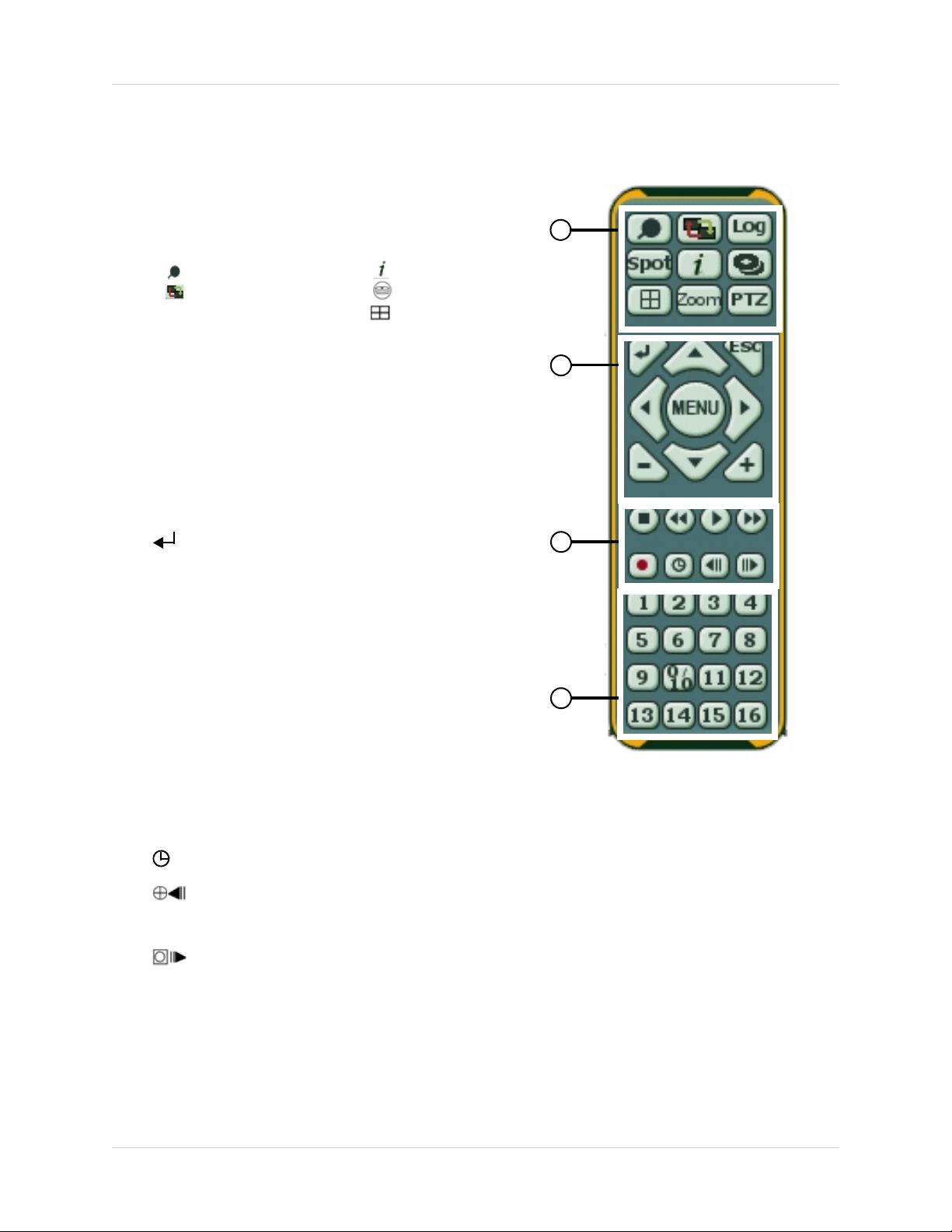
Figure 4.1 Virtual Remote
4
• : Time Search
•
:Window
Positioning
• Log
• Spot Out
• System Info
• Backup
• : Display Mode
• Zoom
• PTZ
Using the Virtual Remote
Right-click anywhere on the screen to open the Virtual
Remote. The Virtual Remote gives you quick access to
many of the system’s features using only a USB mouse
(included).
1.
Quick Function Keys:
2. Navigation/Menu:
S: Move cursor up
•
• T: Move cursor down
• W: Move cursor left
• X: Move cursor right
U: Press to open/close the Main Menu; press to close menu
• MEN
windows
3. Playback controls:
4. Channel butt
•
: ENTER/confirm menu options/selections
• ESC: Close menu windows; press to show/hide the onscreen
display (OSD); press to clear channel indicators (loss, alarm,
etc.)
•
+: Increase values in menu options.
- : Decrease menu options in menu options
•
: Stop playback
•
: Increase reverse playback speed 1X, 2X, 4X, 8X, and 16X
•
art playback; press to switch between forward and reverse
• X: St
playback
: Increase forward playback speed 1X, 2X, 4X, 8X, and 16X
•
•
z: Start manual recording (if scheduled recording is not active)
•
: Starts/stops Schedule Recording
• : During playback, click to pause; click repeatedly for
frame-by-frame playback; during liv
PTZ menu
e viewing, click to open the
• : During playback, click to pause; click repeatedly for
frame-by-frame playback; during live viewing, click to SPOT
OUT
ons: Click to view channels 1~8 individually in full-screen; click to input passwords; when entering
camera titles, click for alpha-numeric characters.
NOTE: The button labeled 0/10 means 0 when entering passwords, and 10 when entering
channel 10 for the 16 channel model DVR.
11
Page 22
Using the System
2
3
1
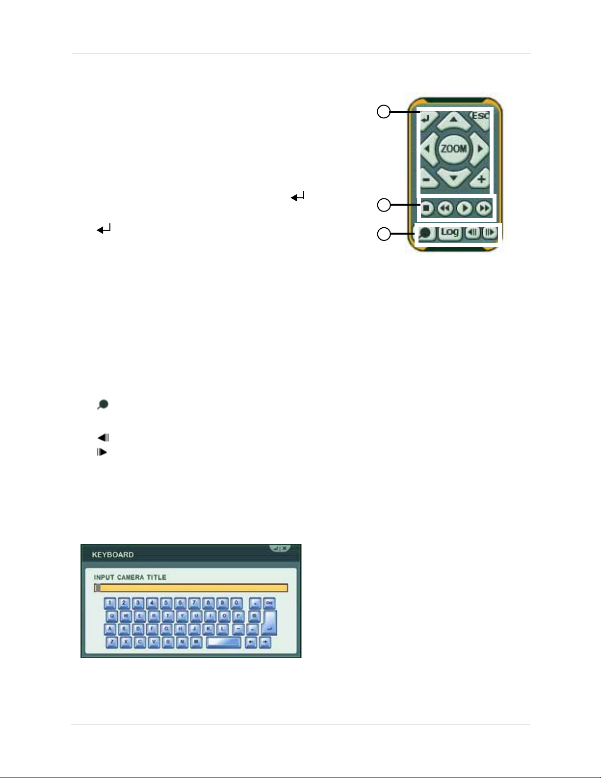
Figure 4.2 Virtual Remote during Playback
Figure 4.3 Virtual Keyboard
Playback
During playback, you can right-click anywhere on the
screen to open a condensed version of the Virtual Remote.
1.
Navigation/Menu:
• S: Move cursor up
• T: Move cursor down
• W: Move cursor left
• X: Move cursor right
• ZOOM:
•
• ESC: Click to close menu windows; click to show/hide the onscreen
•
•
2. Playback controls:
•
•
• X:
•
Click to open/close the Zoom windows. Click to a ctivate
zoom then click + / - t
o increase 2X, 4X.
: Click to confirm menu options/selections
display (OSD); click to clear channel indicators (loss, alarm, etc.)
+: Increase values in menu options.
- : Decrease menu options in menu options
: Stop playback
: Increase reverse playback speed 1X, 2X, 4X, 8X, and 16X
Start playback; press to switch between forward and reverse playback
: Increase forward playback speed 1X, 2X, 4X, 8X, and 16X
3. Quick Function Keys:
• : Click to open the Time Search menu
• Log: Click to open the Log menu
• : During playback, click to pause; click repeatedly for frame-by-frame playback
: During playback, click to pause; click repeatedly for frame-by-frame playback
•
Using the Virtual Keyboard
When configuring certain options, such as Camera Title, the Virtual Keyboard opens to make
mouse input easier.
12
Page 23
Using the System
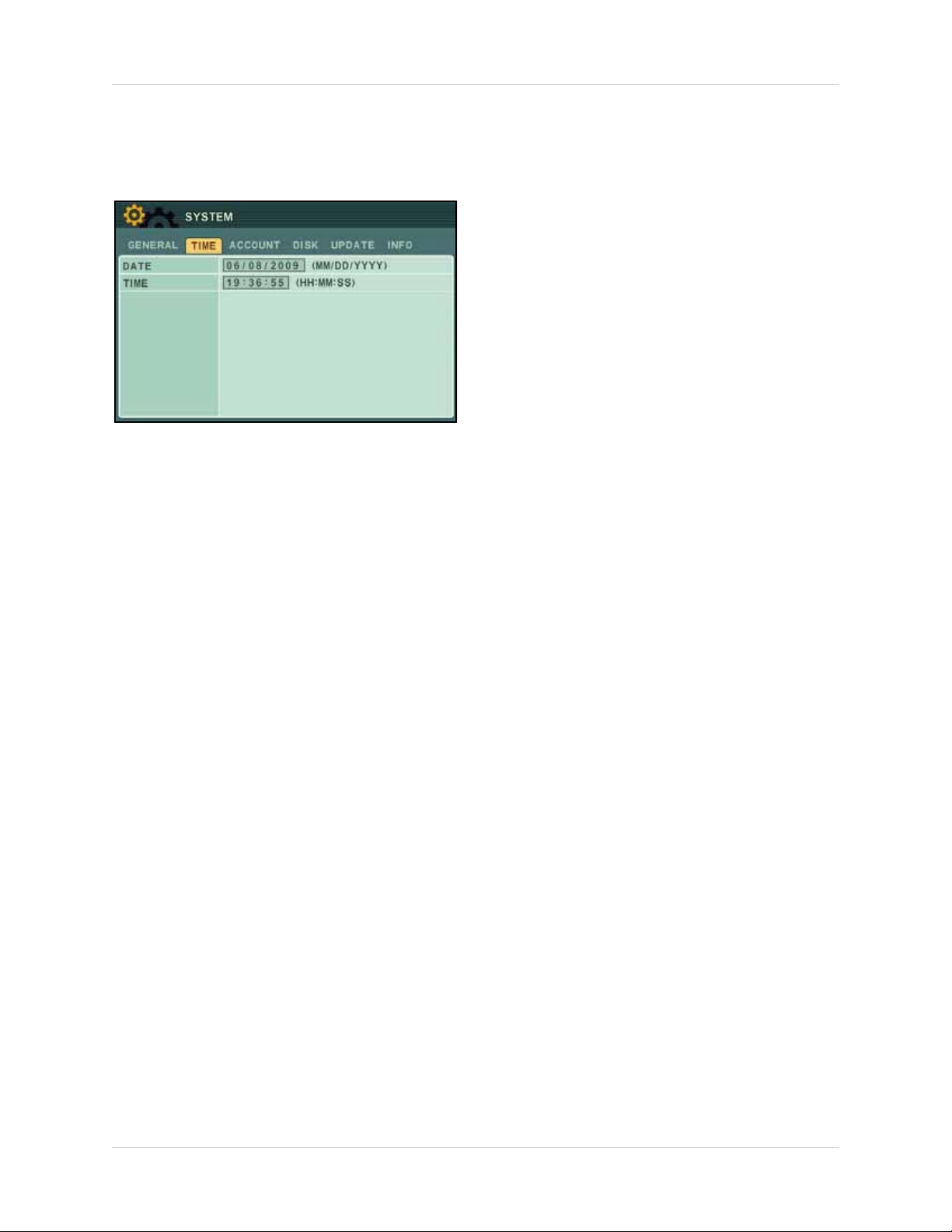
Figure 5.0 Time menu
Setting the Time
It is highly recommended to set the time on the system prior to doing any recording.
NOTE: All recording must be stopped on the system in order to set the time.
To set the date and time:
1. Stop recording on the system by pressing / on
on the remote control and enter your 6-digit system password (by default, 000000).
NOTE: If using the mouse, right-click and then click on the Virtual Remote.
the front panel, or pressing the button
2. Press the MENU
button to open the system menu. Select SYSTEM and press the ENTER
button. The System menu opens.
3. Select the TIM
4. Select DA
5. Select TIME and
NOTE: If using the mouse, use the Virtual Keyboard to enter the date and time.
6. Press the ENTER
7. Press / on the
E tab.
TE and enter the date (mm/dd/yyyy).
enter the time (hh/mm/ss).
button to save your changes.
front panel, or press the button on the remote control to resume
Continuous Recording.
NOTE: If using the mouse, right-click and then click on the Virtual Remote.
13
Page 24
Using the System
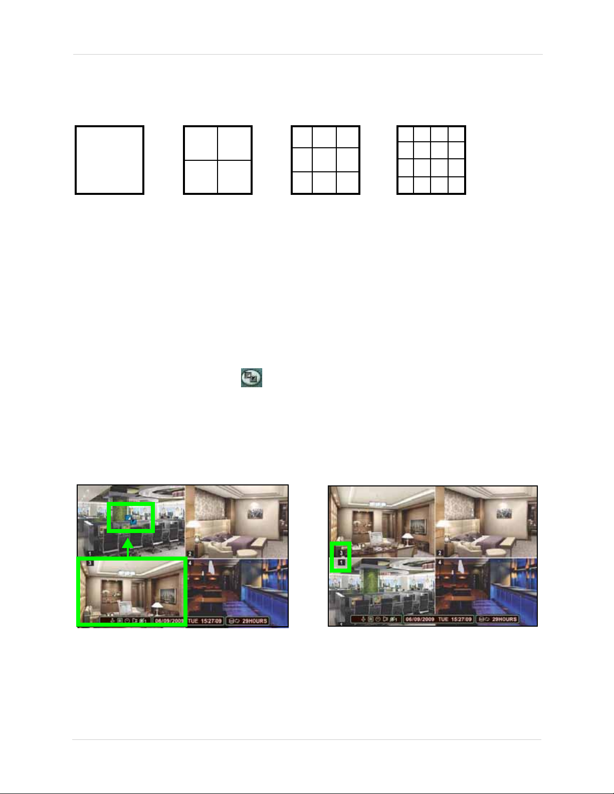
Full-Screen
Quad
Split-Screen 1
Split-Screen 2
(16-channel
models only)
Figure 6.0 Blue Window cursor is in channel 1
Press the 3 button to move channel 3 to the channel 1 position.
Figure 6.1 Channels repositioned
Channel 3 is now in the channel 1 position.
Multi-Screen Display
The system can display channels in full-screen single channel, quad, and multi split-screen
displays.
Repositioning Channels
You can reposition the channels on the display screen. This can be very useful when monitoring a
live location(s).
To reposition the display channels:
1. Using the mouse, remote control, or front panel,
quad display, or in a multi split-screen configuration.
NOTE: Repositioning will not work if the main display screen is in full-screen single channel.
place the main display screen in either a
1. Using the mouse, right-click anywhere on
2. From the Virtual Remote, click
. The Blue Window cursor appears in the top-left channel
the screen to open the Virtual Remote.
(typically channel 1).
3. Reposition the channels through the following:
• Remote Control: Press the button for the channel you wish to place in the location of the Blue
Window cursor. For example, if the cursor is on channel 1, and you want to have channel 4 in
its location, press the 4 button on the remote control
nt Panel: Press the button for the channel you wish to place in the location of the Blue
• Fro
Window cursor
4. Press the STWX to change the location of the Blue Window cursor.
5. Press the
14
ENTER button to save your settings.
Page 25
Using the System
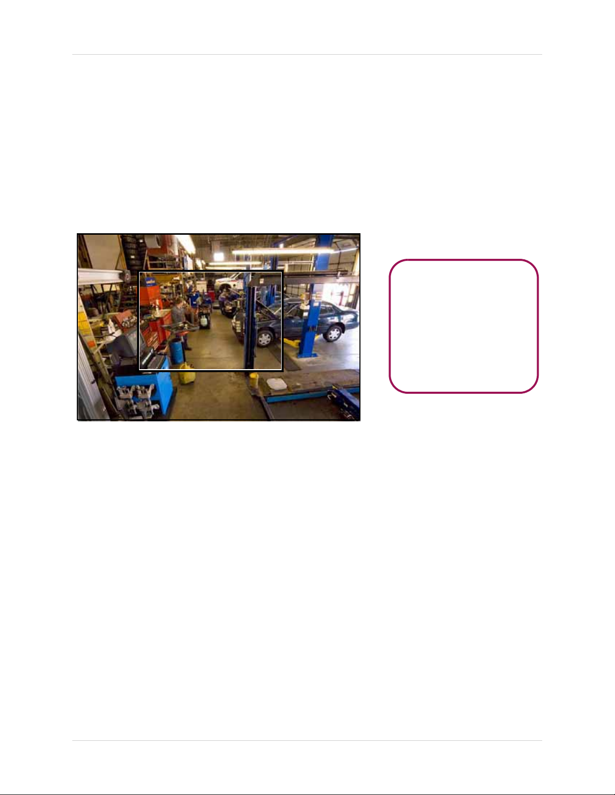
OPTIONAL:
Once the frame is visible,
you can also perform the
following:
• Press + / - to shrink the
frame
• Press the ENTER button
to zoom in 2X
Figure 7.0 Zoom frame (full-screen only)
Zoom
Use the system’s built-in 2X digital zoom to get a closer look at images in full-screen (full-screen
mode only).
To use zoom:
1. From live viewing, press the number buttons on the front panel or remote control to select a
ch
annel to view in full-screen.
NOTE: The zoom function will not work if the main display screen is in quad or split-screen
configurations.
2. Press the ENTER butt
screen.
3. Once the frame is visible, perform any of the following:
• Press
• Press the ENTER button to zoom in 1X
• Press
• Press
STWX to move the frame anywhere on the screen
+ to zoom in 2X; press - to zoom out 1X
STWX to scan the image
on. The OSD disappears. A black frame appears in the center of the
4. Press the
CANCEL/ESC button to exit zoom and return to live viewing.
Sequential Setup (Auto Sequence)
Sequential Setup (Auto Sequence) allows you to view connected cameras in an automatic
sequence. Sequential Setup can include both full-screen and split screen modes.
For more details on Sequential Setup, see see “Sequential Setup” on page 26.
15
Page 26
RECORDING
1
2
3
4
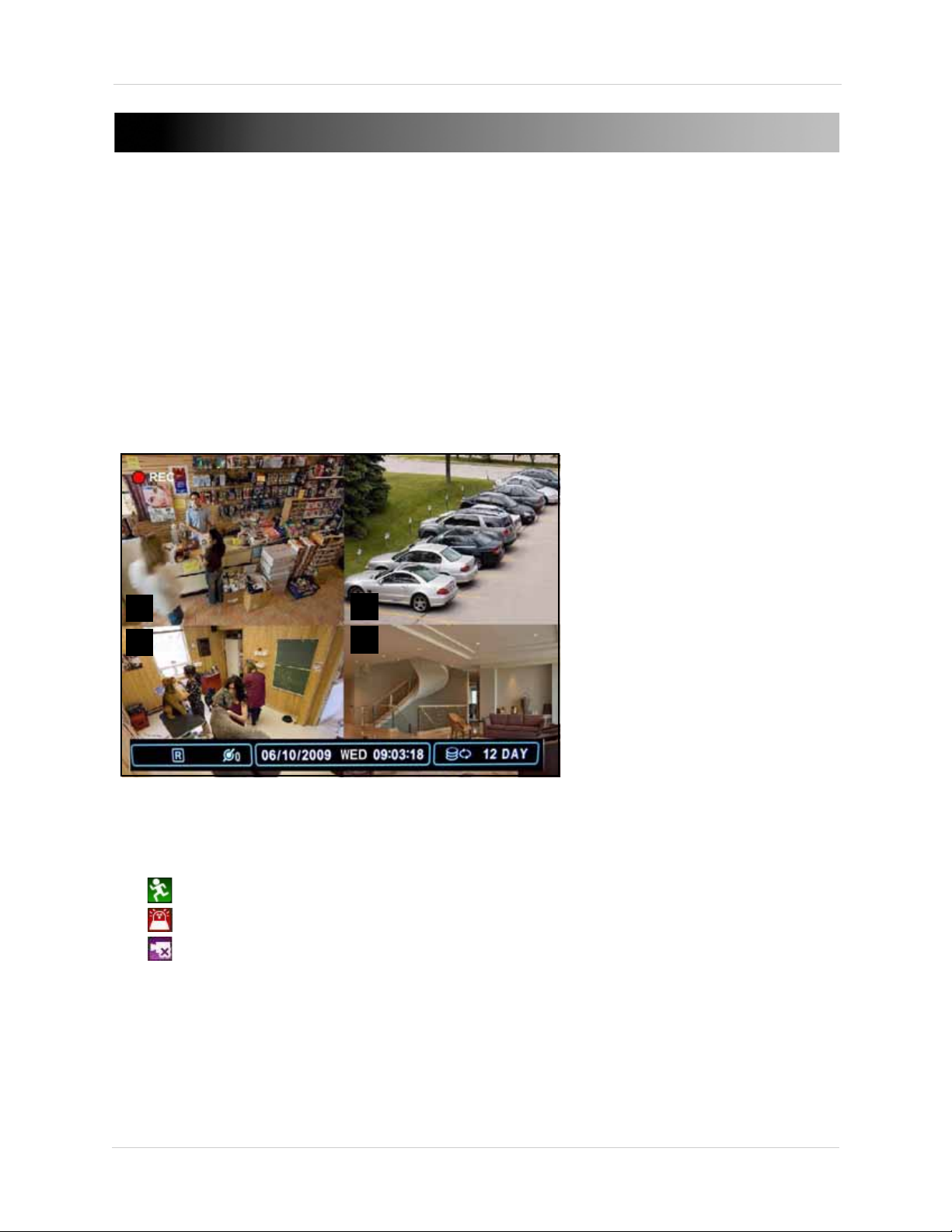
Figure 8.0 Continuous recording on all channels (4CH model shown)
• In this example,
Continuous Recording is
on ALL channels (default)
By default, the system is set to immediately record at startup from connected cameras—
continuous recording. It is highly recommended to keep continuous recording on at all times.
The system can perform Continuous Recording, E
However, the system can only perform one type of recording at a given time.
vent Recording, and Schedule Recording.
Continuous Recording
By default, all camera channels are enabled with continuous recording. During Continuous
Recording, the REC icon appears in the top left corner of the OSD, "R" appears in the status bar
at the bottom of the OSD, and any connected cameras will have their channel numbers in RED (see
figure 0.0).
Event Recording
The system includes three modes of event recording:
• Mo
• Alarm: The system records when an alarm or sensor is triggered
• Video Loss: The system records when a camera is disconnected or suffers video loss. The
system employs a pre-record function to capture video seconds before the video loss occurred
You can customize the recording parameters (video quality, frames-per-second) of Event Recording in the
Record menu. See “RECORD” on page 28.
16
tion: The system only records when motion is detected by the affected camera
Page 27
Recording
1
2
3
4
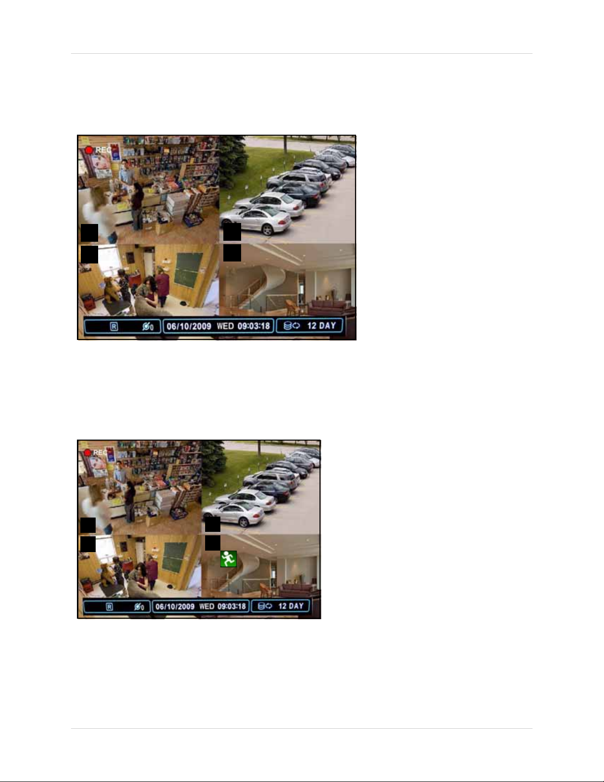
Figure 8.1 Motion assigned to channel 4 (4CH model shown)
• In this example, motion
detection was assigned to
camera 4, so the channel
number is WHITE
• Continuous Recording
remains on channels 1~3
1
2
3
4
Figure 8.2 Motion was detected on camera 4 (4CH model shown)
• In this example, motion was
detected on camera 4—the
motion icon appears and the
channel number turns RED
• Continuous Recording
remains on channels 1~3
Motion
Motion Detection must be applied to specific cameras. If you assign Motion Detection to a camera,
that camera will only record when a motion event is triggered. The camera enabled with Motion
Detection will have a
WHITE number on the OSD (see figure 8.1).
NOTE: A white number can also indicate that recording on a camera has been disabled. For
better security it is highly recommended to keep continuous recording for all cameras on at
all times. Use caution when assigning motion detection to specific cameras.
When motion is detected by the camera, the motion icon will appear, and the channel number will
RED (see figure 8.2).
turn
NOTE: Press the CANCEL/ESC button on the remote control, front panel, or Virtual Remote to
clear the motion icon.
NOTE: If you assign motion detection to ALL cameras, the REC icon will not appear in the top-left
corner, but the "R" will remain in the status bar of the OSD.
17
Page 28
Recording
Motion-only recording
enabled for channel 1
Alarm
When an alarm is triggered, the system will continue to record, but can apply unique recording
parameters that you can set in the Alarm menu (Main Menu>Alarm). For details, see “EVENT” on
page 30.
NOTE: Press the CANCEL/ESC button on the remote control, front panel, or Virtual Remote to
clear the alarm icon.
Video Loss
If a camera is disconnected or is damaged, the video loss icon will appear for the affected channel.
The channel number will turn WHITE.
NOTE: Once video has been restored, press the CANCEL/ESC button on the remote control, front
panel, or Virtual Remote to clear the video loss icon.
Setting Motion-only Recording
The system can record in "Motion-only" recording. During Motion-only Recording, the system
records during motion events, but will temporarily pause recording (on a particular channel)
when there is no movement.
ENABLING MOTION-ONLY RECORDING
Step 1 of 3: Enable Motion recording in the Recording schedule
1. Press the MENU butt
menu.
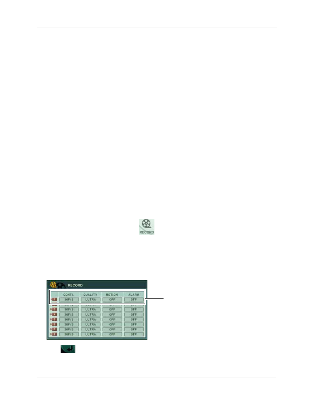
2. From the main menu, click RECORD ( ).
3. Configure the following for the channel you wish to enable motion:
• CONT
• MOTION: Select ON.
• QUALITY: Select the desired video quality.
• ALARM: Select ON if you wish to enable Alarm recording.
I. (Continuous recording): Select OFF
on on the front panel, remote control, or virtual remote to open the main
4. Click to save your settings.
18
Page 29
Step 2 of 3 (OPTIONAL): Configure motion detection areas
Select camera
Select all
Custom Select
De-select all
Motion Grid
By default, the entire channel area is selected for motion recor
ding. Follow the steps below to
customize the area of the channel that you wish to enable motion recording.
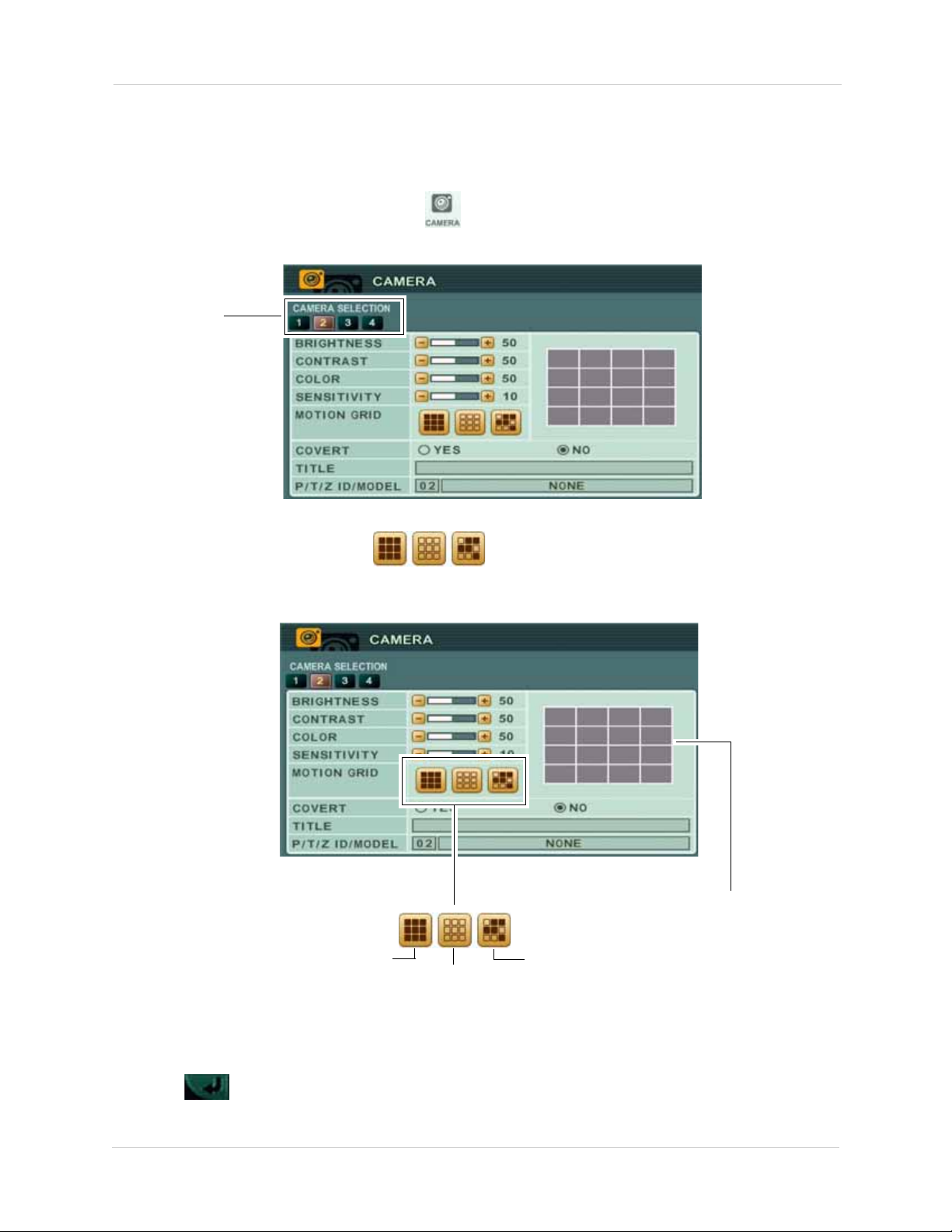
1. From the main menu, click CA
MERA ( ).
2. From the camera section tab, click on the camera that has motion enabled.
3. Beside MOTION GRID, use the buttons to select all, or select a certain
portion of the screen that will detect motion. In the motion grid, you can select the areas that
ou wish to monitor for motion.
y
NOTE: If you use Custom Select, double-click the Motion Grid on the area that you wish to enable
motion. Motion activated areas highlight with a blue grid.
4. Click to save your settings.
19
Page 30
Step 3 of 3: Configuring Motion Recording frame rates
You can configure the recording frame rate when the system detects motion. For example, you
may want th
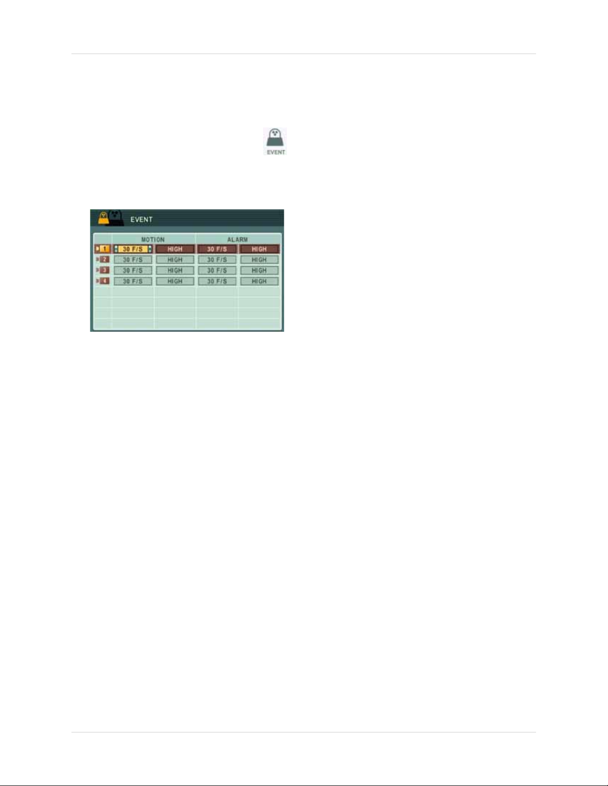
1. From the Main Menu, click EVENT ( ).
2. Configure the following beside the channel that has motion enabled:
• MO
e system to record in a higher frame rate (30FPS) during motion recording.
TION: Select the frame rate the system will record at when it detects motion (i.e 30F/S)
• Select the recording quality (LOW, MIDDLE, SUPER, HIGH, ULTRA)
Final Results
• When the system detects motion, the system begins recording as a "Motion" event. The system
r
ecords at a specific frame rate designated by the user.
• When the post-recording alarm ends, the system pauses recording in the particular channel
where motion-only recording was enabled.
• The system resumes motion-recording when it detects motion.
Setting Continuous & Motion Recording (C+M)
In Continuous and Motion recording mode, the system records 24 hours a day. But as soon as a
camera detects motion, the system records in Motion recording mode. This allows the system to
record at higher frame rates during motion recording, and mark the video as an "event".
Step 1 of 2: Enable Continuous and Motion
1. From the RECORD menu, configure the following on the cameras that will record in C+M:
• CONT
• MOTION: Select ON.
• QUALITY: Select the desired video quality during Motion and Alarm recording.
• ALARM: Turn ON/OFF to enable/disable Alarm recording.
• ALARM: Select ON if you wish to enable Alarm recording.
I. (Continuous): Select the continuous recording frame rate (i.e. 15 F/S)
recording
20
Page 31

2. Click to save your settings.
CONTI. is set to 30F/S. This means Channel 2 will record at 30 FPS during continuous recording.
Motion is set to ON. This means the system will start motion recording when the system detects motion.
Enter the desired reco rdin g fr ame rate during Motion recording
Enter the image
quality during
Motion recording
Step 2 of 2 : Configure Motion Recording frame rates
1. From the Main Menu, click EVENT ( ).
2. Configure the following beside the channel that has motion enabled:
• MO
TION: Select the frame rate the system will record at when it detects motion (i.e 30F/S)
• Select the recording quality (LOW, MIDDLE, SUPER, HIGH, ULTRA)
Recording
3. Click to save your settings
Final Results
• The system records continuously with the assigned parameters. In this example, the system
w
• When the system detects motion, Motion recording begins. In this example, the system will
record at 30 FPS when motion is detected (Motion Recording).
• When the post-alarm recording ends, Motion recording stops, and continuous recording
resumes at 15 FPS.
ill record at 15 FPS during continuous recording.
21
Page 32

Recording
Figure 8.3 Schedule Recording screen
ATTENTION: Schedule Recording takes priority over all other recording modes.
Schedule Recording
Schedule Recording can be set manually or at startup. Schedule Recording features customizable
recording parameters that you assign to each camera.
The Schedule recording icon—
icon, schedule recording is NOT ENABLED.
For details on setting a recording schedule, see “SCHEDULE” on page 28.
—indicates schedule recording is enabled. If you do not see the
Recording Audio
The system can record one channel of audio. You must have an audio enabled camera or
self-powered microphone connected to the system in order to use this function. For details on
connected audio recording devices, see “Appendix K: Using Listen-in Audio” on page 142.
22
Page 33

PLAYBACK
Figure 9.0 Playback display view
View recorded video on the system through playback mode.
Playback
To begin playback:
1. Press the WX
most recently recorded video.
2. Press the following buttons on the remote control to use playback functions:
WX: Press to switch between forward and reverse playback
•
• : Press to pause playback; press repeatedly for frame-by-frame reverse playback
• : Press to pause playback; press repeatedly for frame-by-frame forward playback
: Press to increase reverse playback speed 1X, 2X, 4X, 8X, and 16X
•
: Press to increase forward playback speed 1X, 2X, 4X, 8X, and 16X
•
: Press to stop playback and return to live viewing
•
button on the remote control. The system will play the last few minutes of the
23
Page 34

Search
Figure 10.0 Time Search menu
Figure 10.1 Time Search sub-menu
SEARCH
Search for recorded video data on the system using the Time Search menu.
To open the Time Search menu:
• Press the
To search for recorded video:
1. Press
2. Press
3. Press
the ENTER button. The detailed Time Search menu opens.
WX to select the month.
T to move the cursor to the calendar. The date is highlighted with a black square.
STWX to select dates with either Alarm, Motion, or Normal recordings and press
button on the front panel or remote control
4. Press
ENTER button. Recording blocks are distinguished by Alarm (red), Motion (green), and
Normal (orange).
5. Use the playback buttons on the remote control or the front panel to control playback.
6. Press
24
STWX to select recording blocks in Hour, Minute, or Camera and then press the
to stop playback and return to live viewing.
Page 35

USING THE MAIN MENU
Figure 11.0 System Main Menu
1
2
3
4
5
6
7
8
To open the Main Menu:
• Press the MENU button
on the front panel or the remote control
Using the Main Menu
1. DISPLA
Sequence settings.
2. CA
3. RECO
rate, and motion.
4. SC
5. EVE
6. DEVICE:
7. NE
8. SY
HEDULE: Customize four kinds of recording modes according to a daily or weekly
schedule.
STEM: Configure various system settings including date/time, users, Quick Setup, HDD
settings, and system information.
Y: Adjust OSD borders, camera titles, colors, split-screen configuration, and Auto
MERA: Adjust brightness, color, contrast, title, PTZ settings, and enable/disable convert.
RD: Enable/disable recording for each camera, configure the recording quality, frame
NT: Configure motion recording, and alarm recording settings.
Configure post recording time, key sensitivity, audio recording, and alarm settings.
TWORK: Configure IP, email, and DDNS settings.
25
Page 36

Using the Main Menu
Figure 12.0 Display menu
Figure 12.1 Auto Sequence setup
DISPLAY
Use the Display menu to configure
the OSD and Auto Sequence
settings.
To change display settings:
1. Select the DI
configure the following:
• STATUS BAR: Select to Show or Hide the
status bar on the OSD.
MERA: Select to show the CAMERA NO. or
• CA
the CAMERA TITLE or both.
• BORDE
of the OSD: WHITE, BLACK, DARK GREY, or
GREY
CKGROUND: Set the background color for
• BA
disconnected cameras on the main display:
GRAY, WHITE, BLUE, or DARK GREY
LIT MODE: Set up to four split-screen
• SP
display modes
QUICK SETUP: Select ON/OFF to enable/disable
•
the quick setup menu. By default, Quick Setup
is OFF.
2. Press ENTER to save your changes and exit.
SPLAY SETUP tab, and
R LINE: Set the color for the borders
Sequential Setup
Configure Sequential Setup (Auto Sequence)
settings.
To configure Sequential Setup settings:
1. Select the SEQUENTIAL SETUP t
configure the following:
• DWELL TIME: Set from 1~30 seconds.
• SEQ. MODE: Se
channel full-screen to 8-channel
split-screen
NOTE:
t the display mode, from single
You
must
select one of these
display modes to enable Auto Sequence
mode. If none of these modes are
selected, Auto Sequence
• FULL SCREEN: Select channels for
full-screen display. If selected, these
channels will appear in full-screen during
Auto Sequence mode
2. Press the ENTER button to save your settings and enable Auto Sequence. Auto Sequence will immediately begin.
3. Press the DI
SPLAY button to stop Auto
Sequence.
Auto Sequence with Front Panel and
Remote Control
Once you have configured the Auto Sequence
settings in the Display menu, you can use the
remote control to turn Auto Sequence on/off.
ab and
will not
begin.
26
To enable/disable Auto Sequence:
1. Press and hold on the front panel or remote control for 2 seconds.
2. To exit press . The main screen will return to a quad display.
Page 37

Using the Main Menu
Figure 13.0 Camera menu
Figure 14.0 Motion settings in the Camera menu.
Select all
De-select all
Custom Select
CAMERA
Configure various camera settings,
such as brightness, contrast, title,
and covert.
To configure camera settings:
1. Under CAMERA SELECTION, press
select the camera.
2. Press
T to configure the following:
• BRIGHTNESS, CONTRAST, COLOR: Adjust
from 0~100.
WX to
3. Repeat for other camera connected to the system.
4. Press
CANCEL/ESC to close remaining menu
ENTER to save your settings. Press
windows.
CONFIGURING MOTION
Configure the motion grid and motion
sensitivity for specific channels.
NOTE: If motion detection is applied to a
camera, the system will record from that
camera
only when motion is detected.
• SENSITIVITY : Se
the system. The greater the number, the
more sensitive the system is to motion.
• MOTION GRID:
that you wish to enable motion recording.
VERT: Select YES/NO. If YES, the camera
• CO
channel will be obscured from live viewing to
give the impression that no camera is
recording. Use this option if the display
monitor is in public view.
NOTE:
The Covert channel will use the
lect the motion sensitivity of
Select the area of the screen
same background color as a
disconnected camera. To change the
background color, see “DISPLAY” on
page 26.
• TITLE: Use the alpha-numeric buttons on the
remote control to enter a name/title for the
camera. Press WX to move the cursor left/
right. If you make a mistake, press CANCEL/
ESC to return to the Main Menu and start
again.
• PTZ ID: Ente
match the camera channel to which you have
connected the PTZ camera)
• PTZ MODEL: Sel
connected PTZ camera (not included).
r your PTZ ID (PTZ ID should
ect the model of your
To configure motion settings:
1. Press
and press
T to select CAMERA SELECTION
WX to select the camera that
you wish to configure.
2. Press
T to select SENSITIVITY, and adjust
from 1~20. The higher the number, the
greater the sensitivity.
3. Press
T to select MOTION GRID.
4. Select to select the area of the motion grid that you wish to highlight.
5. Click on the area of the grid
ou wish to enable motion
that y
recording. A green motion
icon appears on the grid.
6. Press
settings. Press
ENTER to save your
CANCEL/ESC to close
remaining menu windows.
27
Page 38

Using the Main Menu
Figure 15.0 Record menu
Setting Motion-only &
Continuous + Motion (C+M) Recording
• For details on how to set the system
record only when motion occurs,
see “Setting Motion-only
Recording” on page 18.
• For details on how to set the system
to record in Continuous + Motion
mode, see “Setting Continuous &
Motion Recording (C+M)” on
page 20.
Figure 16.0 Alarm Setup
RECORD
Configure recording parameters for
each channel.
To configure recording settings:
1. Press
2. Press
3. Press ENTER to save your settings. Press
ST to select a camera you wish to
configure.
WX to select an option and the
+ / - to configure the following:
press
• CONTI. (Continuous recording): Select
continuous recording frame rate (1~30 fps)
• QUALITY: Sel
SUPER, and ULTRA.
TION: Select ON/OFF. Motion Grid and
• MO
sensitivity must be configured in the Motion
menu. See “CONFIGURING MOTION” on
page 27.
• ALARM: Sel
alarm recordings.
CANCEL/ESC to close remaining menu
windows.
ect LOW, MIDDLE, HIGH,
ect ON or OFF to enable or disable
SCHEDULE
Set four recording modes in a daily
or weekly schedule.
NOTE: Daily has priority over a Weekly
schedule.
To set a recording schedule:
1. Press
2. With a mode selected, configure the
3. Select the CHART tab and select ALL,
4. Enter BEGIN an
WX to select MODE1 (red), MODE2
(orange), MODE3 (green), or MODE4 (blue).
fo
llowing:
• USE: Select ON/OFF. If OFF, the selected
camera(s) will not record.
• QUALITY: Se
SUPER, and ULTRA.
TE: Select 1, 2, 3, 4, 5, 6, 7, 10, or 15 fps.
• RA
TION: Select ON/OFF. Motion Grid and
• MO
sensitivity must be configured in the Motion
menu.
SUN, MON, TUE, WED, THU, FRI, or SAT,
and press the ENTER button or +/-. The
Schedule sub-menu opens.
the MODE for ten time slots.
lect LOW, MIDDLE, HIGH,
d END times, and select
28
Page 39

5. Press the ENTER button to save your
Figure 16.1 Schedule recording
Figure 16.2 Split the overnight recording time
settings. The Schedule sub-menu closes.
The assigned mode appears in the main
Schedule window.
6. Press
CANCEL/ESC to close remaining
menu windows.
7. To enable the recording schedule, press
/ on the front panel or on the
Virtual Remote.
Using the Main Menu
Stopping Scheduled Recording
If you need to stop a recording schedule, press
/ on the front panel or on the Virtual
Remote and enter your 6-digit system
pas
sword (by default, 000000).
NOTE: Always look for the icon in the
status bar. If you do not see the icon,
schedule recording is NOT ENABLED.
Overnight Recording
If you want to program an overnight recording
schedule, you will need to split the time using
the available time slots in the Schedule
sub-menu.
2. Customize the
motion detection for the desired channels.
video quality, frame rate, and
For this example, Mode 1 will have
cameras 1 and 2 set to ULTRA and 15 fps,
while the remaining cameras will be set to
HIGH and 7 fps.
3. Select the
then press the
CHART tab and select MON and
ENTER button. The
Schedule sub-menu opens.
4. Under BEGIN, press the
number buttons on
the front panel or remote control to enter
21:00. Under END, enter 23:59.
NOTE: If using the front panel, you can select
digits by pressing + / -. You need to press + / - to
select 0.
5. Under MODE, select MODE1.
6. Press
the right-hand column. Enter
END, enter
7. Under MODE, select
8. Press the
X to move the cursor to BEGIN in
00:00. Under
08:00.
MODE1.
ENTER button to save your
settings and return to the main Schedule
menu. Mode 1 (red) will appear in the
designated time block in the schedule.
9. Repeat steps 1~8 for Tu
10. Press
/ on the front panel or on
esday~Friday.
the Virtual Remote to enable scheduled
re
cording.
Example
You are a small business owner that wants
your custom recording schedule to record
from 9 PM to 8 AM, Monday to Friday.
To set the schedule:
1. From the Schedule menu, select
MODE1~4.
29
Page 40

EVENT
Figure 17.0 Event menu
Figure 17.2 Device menu
You must stop the system from recording before
you can adjust the settings in the Device menu.
Press the Record button on the remote control
or from the virtual remote, and enter the system
password to stop recording.
Be sure to resume recording once you are
finished.
DEVICE
Configure recording parameters for
motion and alarm recording.
NOTE: An external alarm device is not included with the system.
To configure Motion & Alarm settings:
1. Select the channel that you wish to
c
onfigure.
2. Under MOTION, press
+ / - to adjust the
frames per second (default 30 F/S). Select
the quality of the recording (select from
LOW, MIDDLE, SUPER, HIGH, and ULTRA).
3. Under ALARM, press
+ / - to adjust the
frames per second (default 30 F/S). Select
the quality of the recording (select from
LOW, MIDDLE, SUPER, HIGH, and ULTRA).
Configure post-recording time,
Alarm Out, Alarm Buzzer, and
alarm input settings.
The GENERAL tab
The GENERAL tab allows you to configure Post
Recording time,
Audio recording, Key Tone
(key "beeps"), and Key Sensitivity.
1. Configure the following in the General tab:
• POST RECORD TI
ME: Press + / - to enter
the post recording duration (adjust from
• AUDIO RECORD: Select ON or OFF to
enable or disable audio recording.
• KEY TONE: Select ON or OFF to enable or
disable the "beeps" when a button is
pressed.
• KEY SENSITIVITY: Press the - / + buttons
to adjust the sensitivty of the keys on the
front panel of the system.
2. Press
CANCEL/ESC to close remaining menu
ENTER to save your settings. Press
windows.
30
Page 41

Using the Main Menu
Figure 17.3 Alarm menu
TIP!
If an alarm is triggered on
the system, press the
Cancel/ESC button to
cancel the buzzer (if
enabled). Cancelling the
buzzer
will not
stop
recording.
The ALARM tab
The ALARM tab allows you to configure the
sy
stem Alarm Buzzer and Alarm Input type on
each channel (i.e. N.O and N.C (normally open
and normally closed) settings)).
1. Configure the following in the Alarm tab:
• RECORD C
AMERA: Select ALL if you want
all the cameras to record if motion is
detected. Select 1:1 if you only want the
camera that detected motion to record.
• ALARM BUZZER: Select ON or OFF to
enable or disable the system alarm buzzer.
• ALARM OUT1: Select the type of event that
will trigger an event. Select from ALL
ALARM, ALARM IN 1~8, HDD FAIL, VIDEO
LOSS, MOTION.
• ALL ALARM: Triggers an alarm output
if the hard drive fails, if there is video
loss, motion detection, or an alarm IN
trigger.
• ALARM IN1~8: Triggers an alarm
output
if a device connected to the
ALARM IN block triggers.
• HDD FAIL: Triggers an alarm if the DVR
har
d drive fails.
• VIDEO LOSS: Triggers an alarm if video
l
oss occurs.
• MOTION: Triggers an alarm if the
c
amera detects motion.
• INPUT: Select the alarm type connected to
the particular channel. Select from N.O or
N.C (Normally Open, or Normally Closed).
Alarm recording will take priority over
continuous
recording, even if a camera is
disabled in standard recording parameters.
2. Press
ENTER to save your settings. Press
CANCEL/ESC to close remaining menu
windows.
31
Page 42

Using the Main Menu
Figure 18.0 Network menu (IP setup)
Figure 18.1 Email menu
NETWORK
Configure network and DDNS
options.
To configure IP Setup:
1. Connect an Ethernet cable to the LAN port
the rear panel of the system.
on
2. Disconnect the power cable and let the
tem power down for a few moments.
sys
Reconnect the power cable. The system
automatically powers on.
3. Under CONFIG, select
DHCP allows you to instantly obtain an IP
address when first networking your
system. STATIC IP lets you manually enter
a fixed IP address. If you select STATIC, go
to step 4.
NOTE: DCHP allows you to quickly connect to
your network by obtaining an IP address from
the router. After the initial setup, we recommend
that you disable DHCP and set the IP address
between 1~100. For example, if your IP address
is 192.168.0.107, change the last digits to 90 (i.e.
192.163.0.90). This ensures that port forwarding
will not change in the event of power failure or
resetting of your network.
4. Press ENTER to save your settings. Press
CANCEL/ESC to close remaining menu
windows.
STATIC or DHCP.
EMAIL
Configure settings for email notification of
events on the system.
To configure email settings:
1. Under USE, select
own email server). If you select DEFAULT,
go to step 7. If you select SMTP, go to step
2.
2. Under SMTP SERVER, enter yo
email server.
3. Under SMTP PORT, enter yo
4. Under SMTP AUTH, select
5. Under SMTP USER ID, enter yo
user name.
6. Under SMTP PASSWORD, enter yo
password
.
7. Under EMAIL ADDRESS, enter the
r
ecipient email address for the email
notification. You can add up to five email
addresses.
8. Press
CANCEL/ESC to close remaining windows.
NOTE: When an event is triggered, you will
ENTER to save your settings. Press
receive an email alert. If no events occur in
the next 5 minutes, you will no receive
another email.
If a new event is triggered during that
es, you will only receive the new email
minut
5 minutes after the first email.
DEFAULT or SMTP (your
ur SMTP
ur SMTP port.
ON.
ur SMTP
ur SMTP
32
Page 43

Using the Main Menu
Figure 18.2 DDNS menu
Figure 18.3 MISC menu
Connecting to your system
After you have port forwarded the required
port, created a DDNS account, and enabled
DDNS on your system, you must enter the
DDNS URL into Internet Explorer to access
your DVR.
The DDNS URL must include http:// , the
name of your DDNS URL, followed by a
colon, then the port number of your DVR.
For example:
http://tomsmith.digimerge.net:80
DDNS URL
Port Number
NOTE: If you change your default port
number (port 80) to a different port, you
still need to enter your port number after
the DDNS address.
DDNS
Configure Digimerge DDNS settings.
NOTE: You must register for the FREE
Digimerge DDNS service prior to
configuring DDNS settings.
To configure DDNS settings:
1. Under USE, select
2. Under DOMAIN NAME, enter only the firs
portion of your DDNS domain from the
confirmation email. For example, if your
domain name is tomsmith.digimerge.net,
you only need to enter
field.
3. Under USER ID, enter your
user name
.
4. Under PASSWORD, enter your
DDNS password
DIGIMERGE or OFF.
tomsmith
Digimerge DDNS
.
in the text
Digimerge
MISC
Configure additional network settings.
To configure bandwidth settings:
1. Under BANDWIDTH, select
KBPS
, 256 KBPS, 512 KBPS, 1 MBPS, 2 MBPS,
4 MBPS, 8 MBPS, or UNLIMITED.
NOTE: By default, the system is set to
t
UNLIMITED. Change the bandwidth setting
to maximize your network performance.
2. Press
CANCEL/ESC to close remaining windows.
ENTER to save your settings. Press
64 KBPS, 128
NOTE: Obtain your Digimerge DDNS user
name and password from the confirmation
email.
5. Under DDNS TEST, select
successful, you will see "GOOD." If
unsuccessful, you will see "ERROR." If you
receive an error, please check your
network connections and carefully
re-enter your Digimerge DDNS
information.
6. Press
CANCEL/ESC to close remaining windows.
ENTER to save your settings. Press
START. If
33
Page 44

Using the Main Menu
Figure 19.0 Setup menu
Figure 19.1 Account menu
SYSTEM
Configure System settings.
•
PASSWORD: Select ON/OFF. If ON, the system will
prompt you for a password when opening the main
menu
NOTE: You must set the Password to
"ON" in order to use the Auto Lock.
• FACTO RY DEFA ULT: Select START and press the
ENTER button to restore the system to the original
factory settings
2. Press ENTER to save your settings. Press
CANCEL/ESC to close remaining windows.
TIME
For more details, on setting the date and time,
see “Recording” on page 16.
GENERAL
To configure general system settings:
1. Select the GENERAL tab and configure the
fo
llowing:
• AUTO LOCK: Select ON/OFF. If ON, the front panel
touch-screen will be disabled after 3 minutes of
inactivity. Enter your system password (by default,
000000) to disable.
NOTE: Auto Lock is not available if
Password is set to "OFF."
• RECORD MODE: Displays the current resolution
on the system. To edit the resolution, you must stop
the system recording. Once the DVR stops
recording, return to the System menu, and click on
the RECORD MODE field to edit the recording
resolution.
•
PB INTERLACE: Select ON/OFF. If ON, image
flickering will be reduced, but overall image quality
may also be reduced. If OFF, there will be better
image quality on still images, but image flickering
during live viewing and playback.
•
RUN ON BOOT: This option sets the default
recording mode when the system starts up. Select
CONTIN. REC for Continuous recording; select
SCHEDULE REC for the system to record
according to a recording schedule(s). For more
details on setting recording schedules, see see
“SCHEDULE” on page 28.
ACCOUNT
Only the ADMIN can configure user authorities
on the system.
To configure user and account settings:
1. Select the ACCOUNT tab, and configure
the f
ollowing:
• USER: Select ADMIN or USER1~5.
• ACTIVATE: Select ON/OFF to enable the settings
for the specific user type
•
AUTHORIZATION: Select MONITORING,
BACKUP, NETWORK, PLAYBACK,
CONFIGURATION, or SHUTDOWN
• PASSWORD: Enter a 6-digit password for the
user
2. Press the ENTER button to save your settings.
34
Page 45

Using the Main Menu
Figure 19.2 Disk menu
ATTENTION: You must stop all recording
before attempting to format the internal HDD.
DISK
Use the Disk menu to format the internal HDD,
external USB flash drive (not included),
external USB HDD, and configure Overwrite
and Disk Monitor settings.
Formatting Disks
To format the internal HDD/external HDD/USB
flash drive:
1. Under the DISK tab, select
select
Memory Stick
Internal HDD, USB HDD, or USB
.
2. Under ACTION, select
begins. Once formatting is complete the
system will reset (internal HDD
3. Press
flash drive
CANCEL/ESC to close windows (USB
only
).
FORMAT and
START. Formatting
only
).
Disk Monitor
If enabled, Disk Monitor will alert you if the
internal HDD fails.
To enable/disable disk monitoring:
1. Under the DISK tab, select
2. Press the
CANCEL/ESC button close
START/STOP.
Auto Delete
Configure the duration the system should keep
the data on the hard drive before it is deleted.
For example, if you choose 12 hours, the
system keeps the last 12 hours of recording,
deleting the older footage.
Prerequisite
• Stop system recording (click the stop
button
password required)
To enable auto-delete:
1. Under AUTO DELETE, select from 12 hours
~ 30
2. Press the
settings.
3. Resume system recording (press the
re
panel).
on the virtual remote; system
days.
ENTER button to save your
cord button on remote control or front
Overwrite
Disk overwrite will overwrite the oldest data on
the
internal HDD once it full.
To enable/disable disk overwrite:
1. Under the DISK, select
select
ON/OFF. If OFF, the system will stop
recording once the HDD is full.
NOTE: By default, the system is set to
overwrite.
2. Press the
ENTER button to save your
settings.
OVERWRITE and
35
Page 46

Using the Main Menu
Figure 19.3 Update menu
Figure 19.4 System Info menu
UPDATE
Use the Update menu to upgrade system
firmware.
NOTE: The system supports most major
brands of USB flash drives with a capacity
of 10 MB ~ 16 GB.
To upgrade firmware:
1. Download the latest firmware update from
the Digimer
2. Copy the firmware to a blank USB flash
e.
driv
NOTE: Do not have any folders on the USB
flash drive—just the firmware file.
3. Connect the USB flash drive to the USB
on the front panel.
port
4. Stop all recording on the system.
NOTE: You must stop all recording in order
to perform the upgrade.
5. Open the Main Menu and select
6. Under the UPDATE tab, select
7. Select
Firmware upgrade begins.
the USH flash drive until the upgrade
process is complete.
buttons or power off the system during the
upgrade process.
ge website.
SYSTEM.
UPDATE.
START and press the ENTER button.
Do not
Do not
remove
press any
INFO
View important system information:
• LANGUAGE: The current system language
• S/W VERSION: The current system
firmware version
• DOMAIN NAME: Your Digimerge DDNS
domain name
• MAC: The physical address of the DVR on
your network
• NETWORK: The IP address of the system
• INTERNAL HDD: 1 HDD, size and space
remaining
• USB (FRONT): The status of the USB port
on the front panel
• USB (REAR):
• 4 Channel models: The status of the USB
mouse port. Note that on the 4 channel
models, the rear USB port is only used
for mouse connectivity.
• 8/16 Channel models: The status of the
USB port.
• IDE BUS: The status of the HDD—will show
"GOOD" or "ERROR"
When upgrade is finished, press the ENTER button
in the prompt window to restart the system.
36
Page 47

Backup
Figure 20.0 Backup menu—USB flash drive
BACKUP
Backup critical video data on your system to a USB flash drive, external USB HDD, or an external
USB CD/DVD-RW drive (not included).
NOTE: The system supports most major brands of USB flash drives with a capacity of 10 MB ~
4 GB. Most major brands of USB HDDs and CD/DVD-RW drives are supported.
USB Flash Drive
To backup recorded video:
1. Connect a blank USB flash drive to the USB
port
on the front panel.
2. Format the USB flash drive if you have not
eady done so. For details on formatting the
alr
USB flash drive, see “DISK” on page 35.
3. Press the
4. Under DEVICE, make sure to select
PANEL)
5. Under SELECT, select specific cameras or
sel
ect ALL. Select
recording. Select all boxes if desired.
6. Under RANGE, enter date and time for the
stem to scan for video. If the system finds a
sy
file, it will immediately begin backing up the
data. Monitor the backup progress in the ACTION frame.
BACKUP button on the front panel.
USB (FRONT
.
NORMAL, ALARM, or MOTION
NOTE: If there is no video available in the range, the system will prompt, "STATUS: NO FILE."
7. Under ACTION, select
8. Once backup is complete, press
9. You will be prompted to re-start recording on the system. Press
prompt, and
Recording.
/ to resume Continuous Recording; press / to resume Schedule
START and press ENTER.
CANCEL/ESC to close remaining windows.
CANCEL/ESC to close the
37
Page 48

Backup
ATTENTION: You must STOP ALL RECORDING on the system prior to backing up any video data to an
external USB HDD or external USB CD/DVD-RW drive.
Figure 20.1 Backup menu—USB HDD
Figure 20.2 Backup menu—USB CD/DVD-RW
External USB HDD
To backup recorded video:
1. Connect an external USB HDD to the USB port on the
fr
ont panel.
2. Format the external USB HDD if you have not already
done so. F
HDD, see “DISK” on page 35.
3. Press the
4. Under DEVICE, make sure to select
5. Under SELECT, select specific cameras or select ALL.
Se
lect
boxes if desired.
6. Under RANGE, enter date and time for the system to
sc
an for video. If the system finds a file, it will immediately begin backing up the data. Monitor
the backup progress in the ACTION frame.
or details on formatting the external USB
BACKUP button on the front panel.
USB HDD.
NORMAL, ALARM, or MOTION recording. Select all
NOTE: If there is no video available in the range, the system will prompt, "STATUS: NO FILE."
7. Under ACTION, select
8. Once backup is complete, press
9. You will be prompted to re-start recording on the system. Press
prompt, and
/ to resume Continuous Recording; press / to resume Schedule
START and press ENTER.
CANCEL/ESC to close remaining windows.
CANCEL/ESC to close the
Recording.
USB CD/DVD-RW
To backup recorded video:
1. Connect an external USB CD/DVD-RW drive to the USB
port
on the front panel.
2. Insert a CD/DVD-R/W disc into the drive.
3. Press the
4. Under DEVICE, make sure to select
5. Under RANGE, enter date and time for the system to
sc
an for video. If the system finds a file, it will
immediately begin backing up the data. Monitor the
backup progress in the ACTION frame.
NOTE: If there is no video available in the range, the
system will prompt, "STATUS: NO FILE."
BACKUP button on the front panel.
USB - CD/DVD-RW.
38
Page 49

Backup
Figure 20.1 Time Search sub-menu
Figure 20.2 Backup menu
6. Under ACTION, select START and press ENTER. If your backup data spans more than one disc, the system will eject the completed disc and prompt you to insert a new blank disc. Backup will continue as normal.
7. Once backup is complete, press
8. You will be prompted to re-start recording on the system. Press
CANCEL/ESC to close remaining windows.
CANCEL/ESC to close the
prompt, and
/ to resume Continuous Recording; press / to resume Schedule
Recording.
Time Search and Backup
Use the Time Search menu to set a Time Range, then use the Backup menu to backup critical
video to a USB flash drive, external USB HDD, or external USB CD/DVD-RW drive (not included).
To set the Time Range:
1. Press the button on the front panel or remote control.
2. Press
3. Press
date is highlighted with a black square.
4. Press
Motion, or Normal recordings and press the
ENTER button. The detailed Time Search menu
opens.
5. Press
Minute, or Camera and then press the ENTER
button. Recording blocks are distinguished by
Alarm (red), Motion (green), and Normal (orange).
WX to select the month.
T to move the cursor to the calendar. The
STWX to select dates with either Alarm,
STWX to select recording blocks in Hour,
6. Press
7. Press
- set a START TIME. The block will turn grey.
STWX to select other blocks in your desired time range. Press + to set the END
TIME. All the block in the time range will turn grey.
8. Press
CANCEL/ESC to exit.
To backup video:
1. Press the
2. Under DEVICE, make sure to select
MEMORY STICK, USB - HDD,
BACKUP button on the front panel.
USB (FRONT) -
or USB - CD/DVD-RW.
3. Under SELECT, select specific cameras or select ALL.
Se
NORMAL, ALARM, or MOTION recording. Select
lect
all boxes if desired.
4. Under RANGE, the START and END TIMES you select in
the Time Sear
5. Under ACTION, select
6. Once backup is complete, press
ch menu should appear.
START and press ENTER.
CANCEL/ESC to close
remaining windows.
39
Page 50

Backup
Figure 20.3 Backup video player file
Figure 20.4 Playback in McdPlayer
NOTE: The "C" button stands
for Capture. The "D" button
stands for de-interlace.
Viewing Backup Video
Along with copying the files, the system adds a Backup Video Player (McdPlayer) and an AVI
converter to the USB flash drive, external HDD, and external USB CD/DVD-RW drive. Use the
Video Player to view the backed up video files on your PC.
NOTE: You can also view the files using the browser-based remote surveillance software.
To view backup video:
1. Connect the USB flash drive or external USB
with the backed up video data to your PC;
HDD
or insert the CD/DVD-R/W disc into your PC’s
CD/DVD-RW drive.
2. McdPlayer should launch automatically. If
orun does not start, search the drive/disc
Aut
and double-click
Backup Video Player. McdPlayer launches and
begins to load your backed up video. For more
details, see “Viewing Backup Video” on
page 40.
NOTE: If the drive contains more than one video
file, first select the file and click
mcdplayer.exe to launch the
OK.
3. When the purple progress bar has loaded, you
an begin to playback the video.
c
40
Page 51

Backup
Figure 20.5 McdPlayer main window (image simulated)
• : Reverse playback -4X
• : Reverse playback -2X
• : Reverse playback -1X
• : Backward step (frame-by-frame)
• : Forward step (frame-by-frame)
• : Forward play 1X
• : Forward play 2X
• : Forward play 4x
Using MCD Player
MCD Player is a small application that the system places on your USB flash drive when you backup
critical video.
To use MCD Player:
1. Connect the USB flash drive or external HDD with the back
insert the CD/DVD-R/W disc into your PC’s CD/DVD-RW drive.
2. Double-click
mcdplayer.exe to launch the Backup Video Player. The Video Player launches and
begins to load your backed up video.
NOTE: If the drive contains more than one video file, first select the file and click OK.
ed up video data to your PC; or
3. When the purple progress bar has loaded, you can begin to playback the video.
4. Use the playback buttons at the top of the main screen to control playback.
5. To view full-screen, click the
number buttons. Click the split-screen buttons to view Quad and
multi Split-Screen.
6. Click and drag the purple playback slider to pause, advance or restart playback.
7. Click
W to for a watermark on the file. If the file has a watermark, the following prompt will
appear: "Has not been tampered with."
8. Click the
NOTE: The date and time will appear below the printed image.
PRINT ICON to immediately print a still frame from the video to your default printer.
41
Page 52

Backup
42
Page 53

CMS-DH CENTRAL MANAGEMENT SOFTWARE
Minimum system requirements
• Windows XP SP 1
• Pentium 4, 2.4Ghz
• 512 MB RAM
• 64 MB AGP video card
• 1024 x 768 monitor resolution
• Direct X 7.0
• 100MB Ethernet LAN
• 10 GB free storage space
Recommended system requirements
• Windows XP SP 1
• Pentium 4, 3.0 Ghz
• 1GB RAM
• 256 MB, PCI-E video card
• 1600 x 1200 monitor resolution
• Direct X 9.0
• 100MB Ethernet LAN
• 40 GB free storage space
CMS-DH is a central management software that allows you to view and manage up to 300 DH200
series DVRs.
System Requirements
Your system must meet the system requirements below:
Prerequisites
• Port forward port 80 (default port) to the router that the DVR is connected to
• Create a DDNS account
• Enable DDNS in the DVR
• Enter the DDNS information into the DVR
• DVR must have access to the Internet or Local Area Network (LAN)
43
Page 54

CMS-DH Central Management Software
Installing CMS-DH
To install CMS-DH:
1. Locate the CMS-DH software included with the software CD.
2. Double-click the CMS-DH setup file. NOTE: Y
continue.
3. Follow the on-screen instructions to install the software.
ou may receive installation warnings.This is normal. Accept the security warnings to
4. Click Ye
s to restart the computer when prompted.
44
Page 55

Starting CMS-DH
Device
Scan button
DVRs that were discovered on the LAN
NOTE: By default, when
adding a DVR from the LAN,
the DVR name will
automatically be named the
last 3 digits of the IP address.
To start CMS-DH:
• Double-click the CMS-DH icon ( ) on the desktop.
Adding a DVR from the local area network (LAN)
Once you open CMS-DH, you can add a DVR.
To add a DVR to CMS-DH:
1. Click Devic
2. Click Scan to l
e.
ocate connected DVRs on the network.
45
Page 56

CMS-DH Central Management Software
Apply
Ok
If you have changed the default password of the DVR,
you must select the DVR from the list, then manually
re-enter the new password in the Password field, and
then click Apply and then OK.
1. Select the DVR you want to connect.
2. Click the Offline button
Double-click to connect to DVR
3. Click on the DVR you wish to add to CMS-DH, and then click Apply>OK.
• The DVR appears on the left panel.
4. Click on the DVR you want to connect, and click the Offline butt
5. Double-click the name of the DVR to connect to the system.
on.
NOTE: T
o add another DVR from the network, you must click the Online button to disconnect
the DVR. Then repeat steps 1-5 to add the new DVR.
46
Page 57

Adding a DVR using a DDNS address
Device
Add
If you have DVR systems that have DDNS set up, you can add them to CMS-DH.
Prerequisites
• Create a DDNS account.
er the DDNS information into the DVR locally.
• Ent
• Port forward the required port (default, port 80) to the router.
To add a DVR using a DDNS address:
1. Make sure the DVRs have been disconnected from CMS-DH. Click De
2. In the Device manager window, click Add.
3. Beside the Type drop-down menu, select DV
R.
vice.
47
Page 58

CMS-DH Central Management Software
Enter the DVR name
Enter the DVR’s Port number
Enter the DVR’s user name
Enter the DVR’s password
Enter the DVR’s
DDNS address
Apply
Ok
4. Enter the following into the blank fields:
• Name: E
nter the DVR name of your choice.
• IP/DDNS: Enter the DVR’s DDNS address (for example tomsmith.digimerge.net)
• Port: Enter the DVR’s port number (by default, port 80)
• User:Enter the DVR’s user name (by default, admin)
• Password:Enter the DVR’s password (by default, 000000)
5. Click A
48
pply>Ok.
Page 59

CMS-DH Central Management Software
1. Click the Offline button
2. Double-click DVR icon
Click the tab to switch DVR
6. Click the Offline button to connect to the DVR. Double-click the DVR icon to begin viewing.
Final Result
Once you have added the DVR, you can add multiple DVRs and view them in the tab.
click on the tabs near the top of the window.
To switch DVR,
49
Page 60

Adding a Virtual DVR
1
DVR # 1
DVR # 2
2
3
4
5
6
7
8
9
A
B
C
D
E
F
G
H
I
Example
A
3
B
6
D
4
8
G
C
Virtual DVR
Video feed from DVR #1
Video feed from DVR #2
In the example below, multiple video sources from two DVRs are grouped into
the Virtual DVR.
(Combined video feeds from DVR #1 & DVR #2)
A virtual DVR allows you to add video sources from multiple DVRs, into one main window.
Prerequisites
• Ensure the DVRs are online, and connected to CMS-DH.
To add a Virtual DVR:
1. Click the Ne
w VDVR button ( ).
50
Page 61

CMS-DH Central Management Software
Virtual DVR icon
Click the + symbol to
expand menu tree
Example
Drag
D
r
a
g
Drag
2. Double-click the virtual DVR icon in the tree menu on the left.
3. Click the + symbol
to expand the DVR menu tree.
4. Drag the desired camera into the Virtual DVR window. NOTE: Y
ou can drag the camera into any desired channel in the virtual DVR.
5. Repeat step 3-4 as required for different DVRs.
51
Page 62

CMS-DH Central Management Software
New Group folder
Creating New Group Folders & Sub folders
Creating group folders and sub-folders helps you organize multiple DVRs. For example, you can
create a new folder for each different DVR.
To create group folders:
1. Right-click on the Group folder, then click Ne
2. Drag the desired DVR into the new folder.
To create a sub-group:
• Right-click on the Group folder, then click Ne
w Group.
w sub group.
52
Page 63

Configuring General System Settings
Setup
To configure general system settings:
CMS-DH Central Management Software
1. Open CMS-DH to access the Login window and then click Setup (Or,
you are logged in to CMS DH)
2. Configure the following in the Setup menu:
• OSD Setup:
(i.e. camera name, time, frame rate etc.).
• Password: Change the CMS-DH login name and password. Enter your desired ID (user name)
and password, and then click OK to save your settings.
• Miscellaneous: Select the items you wish to enable:
Configure the on-screen display items that you want to appear in the channel
click File> Setup once
• Ch
eck Watermark: Checks the system screenshots to ensure that they have not been
tampered.
• Keep Opened
restart the program.
• E-Map Link
occurs (setup required).
• De-interlac
• Sequenc
• Al
ert Window Time: Enter the amount of time the Alert window remains on screen.
• Vi
deo Standard: Select from NTSC or PAL video output.
• Video Render: Select the DirectX type of your system. Select VMR7 if your system uses Direct
X 7.0. Select VMR9 if your system uses Direct X 9.0.
• Video Channel: Select the maximum amount of DVR channels that the software displays.
Choose Max 16 for 16 maximum channels, Max 64 for 64 maximum channels.
• Download Folder: Select the download destination on your hard drive. The download folder
stores saved videos and images. Click the browse button ( ) to select the default download
directory.
Window: Automatically re-opens the windows that were closed after you
Event: When selected, the E-map will open pop-up windows when an event
e: Enable De-interlace to reduce "feathering" effect of video playback.
e Time: Enter the sequence time of each DVR.
53
Page 64

Adding Users
Select the DVR the user will have access to
Select the menus the user will have access to
Add
OK
You can add multiple users to CMS-DH, specifying the DVR menus that each user is allowed to
access.
To add a new user:
1. Log in to CMS-DH.
2. Click Fil
3. Enter the following:
• ID: E
• Password: Enter the desired user password.
• Confirm Password: Re-enter the user password.
e>CMS-DH Account.
nter the desired user name.
4. Under the DVR list, click the checkbox to select the DVR the user will have access to.
5. Under ’Uses’ click the checkbox to select the type of menus the user will have access to.
6. Click Ad
To remove a user:
1. Log in to CMS-DH as the administrator (default user name: ad
2. Click Fil
d and then click OK to save your settings.
min, default password: 0)
e>CMS-DH Account.
3. Click the user name that you wish to remove.
4. Click the Del butt
54
on to remove the user.
Page 65

Recording Video to the hard drive
CMS-DH allows you to record video to your local hard drive. The amount of video that you can
record depends on the size of your computer’s hard drive.
To record video:
1. During live view, click the Rec butt
NOTE: If y
channel in full screen mode, then click the Rec button.
NOTE: If y
mode, and then click the Rec button.
ou want to capture a single channel of video, double-click the channel to view the
ou want to capture all channels, ensure that you are viewing the DVR in split screen
on ( ). The Rec button turns red.
2. Click the Rec but
NOTE: The fil
save directory of the video files, click File>Setup, and look under Download Folder to determine
where the file is saved.
ton ( ) again to stop recording.
e is saved into the default save directory of the CMS-DH software. To locate the
55
Page 66

Playing back recorded video
Open button
Open button
The video is saved as a proprietary file that is playable only by CMS-DH.
To play back previously recorded video files:
1. From the main window, click Fil
2. Click the Open butt
3. Select the desired file you wish to play and click Open.
on.
e>File Playback.
4. Use the video playback controls to watch the video.
56
Page 67

CMS-DH Central Management Software
A
B
CDC
Play button
Remote Search
Remote search allows you to search for archived video on the DVR.
Prerequisite
• Ensure you are connected to the DVR that you wish to search from.
To search for video:
1. Right-click on the DVR that you wish to search video from, then click Remote
2. To search for the video:
a. Click to select the desired month.
b. Select the date of the video.
c. Select the hour.
d. Select the minute.
Search.
3. Click the Play
button to begin watching the video.
57
Page 68

CMS-DH Central Management Software
Use the playback controls to control video speed
Select hour
Select minute
Video speed slider
Video Playback Controls
Once the video begins to play, use the video controls to manipulate video playback.
Local Search
Local search allows you to search for video stored locally on the computer hard drive.
Prerequisite
Ensure you are connected to the DVR that you wish to search from.
To search for videos stored on your hard drive:
1. Right-click on the DVR that you wish to search video from, then click Local
Search.
58
Page 69

2. To search for the video:
A
B
C
D
Play button
Save As button
a. Click to select the desired month.
b. Select the date of the video.
c. Select the hour.
d. Select the minute
3. Click the Play
button to begin watching the video.
Saving Video Files
You can save the proprietary video files to your local hard drive from the Search menu. The video
file ends in a .cms extension, and requires CMS-DH for playback.
To save video files from the search menu:
1. Select the month, date, and time of the video.
2. Click the Sav
e As button.
3. Select the desired save directory, and click OK t
o save the file.
59
Page 70

Converting video files to AVI
AVI Convert button
Select camera
checkbox
Click the browse button to select save directory
Converting proprietary .CMS video files to AVI allows you to play the video on a computer that does
not have the CMS-DH software.
NOTE: T
converter. For details, see “Appendix L: Converting Video Files to AVI” on page 143.
Prerequisite
• Make sure that you are in the Local Search menu (Right-click on the DVR, and click Local
Sear
To convert video files to .AVI:
1. Select the month, date, and time of the video.
o convert video files without using CMS-DH, you can also use the standalone DVI video
ch)
2. Select the checkbox beside the camera you wish to back up video from.
3. Click the browse button ( ) and select the file output directory.
4. Click the AV
I Convert button.
• CMS-DH converts the file, and stores it in the output directory.
60
Page 71

Schedule Recording
Device button
To enable/disable schedule recording:
CMS-DH Central Management Software
1. Right-click on the DVR you wish to configure and then click Contr
• Click Start
to enable schedule recording. Click Stop to stop schedule recording.
ol>Schedule>Start / Stop
Schedule Backup
You can schedule regular backup of video to your local hard drive. The schedule can be configured
to back up 24 hours of video, or during a specified time only.
Prerequisite
• 3GB of hard drive space (backup will not function if ther
e is less than 3GB)
• DVRs must be in offline mode
To configure Schedule Backup settings:
1. Click the DVR that you wish to configure.
2. Click the Device button ( ).
61
Page 72

3. Select On to enable schedule backup.
Select channels you wish to back up
Select channels you wish to back up
4. Select Dail
• Select Hour
y to back up 24 hours of video to your hard drive. Go to step 6.
ly to back up every hour of video to your hard drive. Go to step 5.
5. In the Minute drop-down menu, enter how many minutes the system should wait before
r
ecording. For example, if you enter 10 minutes, the system will backup video footage from
8:10 a.m to 9:10 a.m.
6. In the Hour drop-down menu, enter the time you wish to begin backup. For example, if you
er 5:00pm (05:00hr), the backup will start at 5:00pm, and end at 4:49am (the next day).
ent
Enter the hourly time in 24-hour format.
7. Select the channels that you wish to enable schedule backup.
8. Click A
62
pply and then click OK to save your settings.
Page 73

CMS-DH Central Management Software
Click the Print button to print the image to a printer.
Taking Screen Captures
You can capture screen shots as JPeg or Bitmap images (JPG or BMP).
To take a screen capture:
1. During live view, click Cap
2. Click the Sav
directory, and then click Save.
NOTE: T
the Capture button.
e As button. Enter the desired picture name, and select the desired save
o take a screen capture of a full-screen, double-click the desired channel, then click
ture ( ).
Viewing File Download Status
To check the download status of your video files:
1. Connect to the DVR you wish to check the video status on.
2. Click on To
3. To cancel the download, click Ca
ols> Downlo ad>Sta tus.
ncel.
63
Page 74

Changing viewing modes
Click to change viewing modes
Sequence button
The two DVR tabs will continually switch between eachother
To change the viewing modes of CMS-DH:
1. Log in to CMS-DH, and connect to a DVR.
2. Click ( )to change the viewing mode (single-channel, quad-channel etc).
Sequencing
If you monitor multiple DVRs, you can have each tab change continuously. This process is called
sequencing. You can perform sequencing as long as you have two or more DVRs. Virtual DVR’s
work with sequencing as well.
Prerequisite
• Log in to two or more DVRs
To start a sequence:
• Click the Sequenc
NOTE: T
desired sequence time in seconds, and click Ok.
o change the sequence time, click File>Setup. Under "Miscellaneous", enter the
e button ( ).
64
Page 75

CMS-DH Central Management Software
Example
From the camera list, you can drag
the camera icon over the Jpeg image
Camera list
Jpeg image of a house blueprint
E-Map button
E-Map
The E-Map feature allows you to visually map your cameras over a Jpeg image.
Prerequisite
• Ensure the DVRs are online.
To set up an E-Map:
1. Click the E-Map butt
on ( ).
65
Page 76

2. Click File>Background. Locate the file you wish to import, and then click Open.
Drag
D
r
a
g
Tip:
To rotate the camera, right-click on the
camera, and click Rotate.
Click the desired turning position to rotate the
camera icon.
3. Drag the desired cameras from the camera list, over the image. TIP: You can also drag the DVR icon and E-MAP icon over the image.
E-Map Setup
To configure the E-Map setup menu:
1. Click Fil
2. Configure the following:
• Ti
• Show Description: Show/hide camera name.
• Lock: Locks the camera position.
• Description color: Change e-map font color.
3. Click Ok
66
e>E-Map Setup.
tle: Change the camera title.
to save your settings.
Page 77

CMS-DH Central Management Software
Live channel
Right-click on the camera to open camera
sub-menu options.
Viewing video on E-Map
Once you have mapped your cameras on E-Map, you can view, and search channels from the
E-Map directly.
To view live video on E-Map:
• Double-click on the desired camera icon to open live view.
Configuring E-Map camera settings
To configure E-Map camera settings:
1. Right-click on the camera you wish to
c
onfigure.
2. Configure the following:
• Description Edit: Edit the camera
name on the E-Map.
• Remote Search: Opens the video
search menu.
• Live: Opens a live view window of the
camera.
• Property: View DVR properties.
• Rotate: Rotates the camera icon in the
E-Map.
67
Page 78

CMS-DH Central Management Software
Zoom In/ Zoom Out
Remove Item
Zooming into the E-Map
• To zoom into the E-Map, click the Zoom In / Zoom Out buttons ( ).
Removing camera icon in the E-Map
• Select the camera icon in the e-map, and click the Remove Item button ( ).
Adding Multiple E-Maps
To add multiple E-Maps:
• Right-click the Group folder, and click New E-Map.
To remove the E-Map:
• Right-click on the E-Map, and then click Remo
Tip: After you have cre
E-Map.
ated a second E-Map, you can drag the E-Map icon over a Jpeg image in the
ve.
68
Page 79

Viewing DVR Health
To view the status of the DVR:
1. Select the DVR on the menu tree on the left.
CMS-DH Central Management Software
2. Click the He
alth button ( ).
Closing windows
To close open tabs:
• Click the Close button, and select Close or Close All.
Locking Windows
• To prevent the tab from being dragged, click the Tab Unlock button.
69
Page 80

CMS-DH Central Management Software
Enter the start and stop date and time
Select an event type from
the drop-down menu
Search button
DVR Log
The DVR log allows you to check events that occurred in the DVR, such as hard drive malfunction,
video loss, motion detection, and alarm settings.
To access the DVR log:
1. Connect to the DVR that you wish to view the log from.
2. Right-click on the DVR, and click Log.
3. Configure the following:
gin & End: Specify the start and end date and time.
• Be
• Query: Select the event type you wish to search for
4. Click Sear
NOTE: Sel
ch to populate results.
ect the event and click the Export but ton t o exp or t th e log as a tex t f ile. T he log a llow s
you to see any events logged by the DVR (i.e motion loss etc.).
70
Page 81

CMS-DH Central Management Software
CMS-DH Log button
Playback screen
Search results
Search button
Playback controls
Channel
Begin / End
CMS-DH System Log
The CMS-DH log allows you to view video events that occurred in the system (i.e motion and
camera loss events).
Prerequisite:
• Ensure the DVR(s) are online and connected to CMS-DH
To view the system log:
1. Click the CMS-DH Log button ( ).
2. Configure the following settings:
• Be
gin: Enter the Month, Date, Year, and time you wish to begin to search the log.
• End: Enter the Month, Date, Year, and time you wish the log search to stop.
• Channel: Enter the channel number you wish to search.
3. Click the Sear
ch button.
• A list of results populate. Double-click the event in the search results to begin event playback.
the playback controls to control playback speed.
Use
71
Page 82

CMS-DH Central Management Software
Pan & Tilt
Zoom In
Focus In
Auto Focus
Auto Iris
Go to Preset
Auto Tour
Custom 2
Custom 3
Auto Pan
Auto Pan
Speed Down
Speed Up
PTZ Power
Zoom Out
Focus Out
Open Iris
Close Iris
Save Preset
Custom 1
Auto Tilt
Menu Call
Escape
PTZ
To activate the PTZ control, click the PTZ button ( ).
NOTE: Y
ou must select the channel that has a PTZ camera before using PTZ controls.
Setting PTZ Pre-Sets
1. Click the Pan & Tilt buttons to move the camera to the desired position.
2. Click the Sav
and then click Ok.
e Preset button ( ). Enter the desired pre-set number (between 0 - 9999)
To access a pre-set
• Click the Go t
o Preset button ( ). Enter the pre-set number, and then click Ok.
72
Page 83

System Setup
Setup
To access the full system setup menu:
1. Right-click on the DVR you wish to configure.
CMS-DH Central Management Software
2. Click Setup fr
NOTE: The menu
om the sub-menu to access the full Setup menu.
structure is identical to the menu structure on the local DVR.
73
Page 84

CMS-DH Central Management Software
Upgrading the firmware remotely (DH200+ Series only)
Prerequisite
• Ensure the DVRs are online
wnload the firmware from www.digimerge.com, and extract the firmware file
• Do
To upgrade the DVR firmware using CMS-DH:
1. Right-click on the DVR that you wish to upgrade the firmware.
2. Click on Contr
ol>DVR Setup>Update.
3. Under Image File, click the browse button ( ). Locate the firmware file and then click
Open.
NOTE: The firmware file ends in a .IMG extension.
4. Click Start t
window.
NOTE: Do
o upgrade the system firmware. Wait for the system prompt before you close teh
not exit CMS-DH during the firmware upgrade process. Doing so may corrupt the DVR.
74
Page 85

CMS-DH Central Management Software
Right-click on the device you wish to configure
Configuring Post Event Action Tab
The Post Event Action tab allows your system to alert you when an alarm event triggers the DVR.
For example, when the system detects motion from an input device, the computer speakers plays
a sound to alert you. Or, you can have the CMS-DH software alert you with a pop-up window when
motion is detected.
Setting up Post Event Actions on a NO/NC Device
Prerequisites (If setting up NO/NC Devices)
• Connect the input device into the alarm block in the rear panel of the DVR.
Ensure you have the correct settings for the device (N/O , N/C), and that you have correctly
•
configured the settings in the DVR menu.
• Ensure the DVRs are online.
To configure the Post Event Action tab:
1. Expand the menu tree under the desired DVR that you wish to configure.
2. Under Alarm Input, right-click the number block that your device is connected into.
3. Click Po
st Event Action.
4. Configure the following:
• Events: Select Alarm Input ON or Alarm Input OFF
•
Command: Select from Play Sound or None.
75
Page 86

CMS-DH Central Management Software
Click here to configure the Command and Parameter settings
• Parameter: Select the desired alert sound you want the computer to play.
5. Click Apply and then OK to save your settings.
6. Under Alarm Output, right-click the light bulb icon, and click Contr
7. Click Alarm Output On or Alarm Output Off. This dep
8. Click A
pply and then OK to save your settings.
ends on your device type (N/O or N/C).
ol.
When an alarm is triggered, the system will play a sound on
the computer.
Configuring Alarm Output
To configure the alarm output type:
1. Under Alarm Output, right-click the light bulb icon, and click Contr
2. Click Al
alarm out device
76
arm output on to enable the alarm out device, or Alarm output off to disable the
ol.
Page 87

CMS-DH Central Management Software
Setting message pop-up notifications
You can configure CMS-DH to produce message pop-up windows when an event occurs.
To configure CMS-DH to produce message pop-up events:
1. Expand the menu tree under the desired DVR that you wish to configure.
2. Right-click on the camera you wish to set alerts for, and click Post E
vent Action.
3. In the Events drop-down menu, select the type of event that will trigger CMS-DH to produce a
pop-up window when an e
4. In the Device drop-down menu, select the Sys
5. Under the Sub Type drop-down menu, select Wi
select Alert Window.
vent is detected.
tem.
ndow. Under the Command drop-down menu,
6. Click A
pply and then click OK.
77
Page 88

CMS-DH Central Management Software
Result
When the camera detects motion, a pop-up window appears on the bottom-right corner of the
screen
to alert you.
Setting Video pop-up notifications
You can configure CMS-DH to produce video pop-up windows when an event occurs.
To configure CMS-DH to produce video pop-up events:
1. Expand the menu tree under the desired DVR that you wish to configure.
2. Right-click on the camera you wish to set alerts for, and click Post E
vent Action.
78
Page 89

CMS-DH Central Management Software
3. In the Events drop-down menu, select the type of event that will trigger CMS-DH to produce a pop-up window when an event is detected.
4. In the Device drop-down menu, select the name of your DVR.
5. Under the Sub Type drop-down menu, select Came
6. Under Su
7. Under Command, sel
8. Click A
b No., select the channel number you wish to appear as a pop-up alert.
ect Live Video.
pply and then click OK to save your settings.
ra.
Result
When the camera detects motion, a pop-up window appears with live video.
79
Page 90

CMS-DH Central Management Software
POS data search
Configuring other Post Action Events
Under the Command drop-down menu, there are several commands that CMS-DH can output.
• GoTo PTZ: Opens the PTZ camera.
o Tour: Opens the PTZ camera and starts the Auto Tour.
• Aut
• Auto Pan: Opens the PTZ camera and starts the Auto Pan feature.
• Auto Tilt: Opens the PTZ camera and causes the PTZ camera to Auto Tilt.
• Live: Opens a live video window.
• Record: Begins live recording.
POS Data Search
The POS Data Search function is not available for the DH200+ series.
80
Page 91

CMS-DH Central Management Software
Drag the tab out to move it into a different screen.
Running CMS-DH on multiple monitors
CMS-DH can support a maximum of 8 monitors on a single system. Running 8 monitors is
extremely resource intensive. The recommended system specifications is listed below. If your
system does not meet the requirements below, you may experience slow system performance.
Minimum system recommendations to run CMS-DH on multiple monitors
• Intel Core i5 or i7 processor
• 6 GB of RAM
A motherboard that can support up to four (4) PCI-E video cards
•
• Geforce 9500 GT video card,1GB or greater
To run CMS-DH on multiple monitors:
1. Connect to CMS-DH. Open the desired DVR’s / E-Maps etc. that you wish to view.
2. Drag the desired tabs to a different monitor.
3. Repeat as required.
Final Result
81
Page 92

iSMS Client (Remote Viewing on the Mac)
Double-click to start installation
Enter the admin password
when prompted
iSMS Client (Remote Viewing on the Mac)
The iSMS Client allows you to remotely connect and configure your DH200 Series DVR using the
Safari browser in Mac OSX 10.6.
System Requirements
Your system must meet or exceed the requirements below before installing the iSMS Client:
•
Operating System: Mac OSX 10.6 or later
CPU: Intel Core Duo series CPU or higher
•
•
Memory (RAM): 1024 GB
•
Video Card memory: 256 MB
•
Free Hard Drive space: 2GB
•
Video Resolution: 1024 x 768
Prerequisites
• Download the iSMS client from www.digimerge.com, under the DH200 product page
• Port
• You must create a DDNS account, and have the DDNS settings configured in your DVR
• The DVR must have internet access
• You must have a Digimerge DDNS address to log in remotely
80 (or whichever port your system is using) must be port forwarded to your router
Installation Steps
To install the iSMS Client:
1. Double-click on the iSMS Client icon.
2. Follow the on-screen instructions to ins
when prompted to install the software.
tall the software. Enter your password
82
Page 93

Using the iSMS Client
Enter the DVR’s DDNS address here
Click to change save directory
File Open button
The iSMS client supports a
maximum of three (3)
connected users.
Note
Using the iSMS Client
To open the iSMS client:
1. Locate the iSMS program in the Applications folder.
2. Double-click the iSMS icon( )to start the program. The iSMS login window opens.
To log in to your DVR remotely:
1. In the Host Port field, enter the DDNS address of
your DVR in full, including the port number.
(i.e. tomsmith.digimerge.net:80)
2. In the User Name field, enter
3. In the Password field, enter your DVR password (by default,
4. Click
Connect to log in to the system.
admin.
000000)
To change the save directory:
1. Click the directory name under "Backup".
2. Select the desired save directory.
3. Click
Open to apply your changes.
To delete an account:
1. Select the DDNS address beside the Host Port drop-down menu.
2. Click the
To view a previously saved video on the hard drive:
1. Click the
Delete button to remove the account.
File Open button.
2. Locate the directory of the video. Select the video and then click
Open to begin video playback.
83
Page 94

Using the iSMS Client
1. Channel numbers
2. Viewing Modes
3. PTZ Menu
4. Screen Capture
7. Main Viewing window
6. Record
5. Hide menu button
iSMS Interface
The iSMS Interface displays all connected channels of your DVR.
1.
Channel Numbers: Click the desired channel to view in full screen.
2.
Viewing Modes: Click the icons to switch viewing modes (i.e split screen, quad-view)
3.
PTZ Menu: Opens the PTZ menu.
4.
Screen Capture: Takes a picture of the main viewing window, and saves it to the hard drive to
the save directory you specifiy.
Hide Menu button: Collapses the tool bar and hides the interface functions.
5.
6.
Record: Click to record video of the selected channel. Click again to stop recording. The file
saves to the directory you specify.
84
Page 95

To take a screen capture:
Enter image name
A video save folder looks similar to the image above.
1. Click the Screen Capture button ( ).
2. Enter an image name into the blank field, and
To record live video:
Using the iSMS Client
then click Save or click Print.
1. Click the Record button ( ). The record button turns red ( ).
2. Click the Record button again to stop the recording.
NOTE: The video file saves into a folder to the save directory you specify.
To view recorded video:
1. In the tool bar, click
DVR>File Play.
2. Locate the video file on your hard drive.
• The video file ends in a
.cms extension.
3. Click
Open to view your saved file.
85
Page 96

Using the iSMS Client
Configuring OSD Settings
The iSMS interface can be customized to show less or more information.
To configure the iSMS display settings:
1. From the tool bar, click
2. Select the display settings that you wish to remove by clicking the checkboxes.
3. Close the menu to save your settings.
iSMS>Preferences.
Searching for video remotely
You can search for video from your DVR remotely, and back up the file to your local hard drive.
To search for video on yo
1. From the tool bar, click
2. From the Remote Search menu, perform the following: a. Select the Month/Year
b. From the Calendar, select the date
c. Select the Hour and Minute
d. Select the channels you wish to search under by clicking the check boxes
ur DVR remotely:
DVR>Remote Search.
86
Page 97

5. Click the Playback button to begin viewing.
Month / Yea r
Calendar
Hour
Minute
Download
Playback
Channel selection
During video download, the status bar indicates the progress of the saved video.
OR
Click the
Download button to save the video to your default save directory.
Using the iSMS Client
Download Progress bar
87
Page 98

Using the iSMS Client
Playback controls
Drag the video slider to skip through the video
Rewind
Reverse Step (1 frame)
Play
Forward Step (1 frame)
Fast Forward
• Click the Rewind or Fast
Forward buttons repeatedly
to increase the speed
• The Reverse Step and
Forward step button
advances the video by
one frame
Playback Window
• Use the Playback Controls to manipulate video speed
88
Page 99

Searching for video locally
Month / Yea r
Calendar
Hour
Minute
Playback
Channel selection
To search for local videos saved on your hard drive:
1. From the toolbar, click
2. From the Remote Search menu, perform the following: a. Select the Month/Year .
b. From the Calendar, select the date.
c. Select the Hour and Minute
d. Select the channels you wish to search under by clicking the check boxes
DVR>Local Search.
Using the iSMS Client
5. Click the
Playback button to begin viewing. The Playback window opens.
89
Page 100

Using the iSMS Client
Configuring PTZ settings
If your DVR has a PTZ (pan tilt zoom) camera installed, you can control the PTZ camera through
the PTZ menu.
To open the PTZ menu:
• Click from the main interface.
PTZ Controls
To control your PTZ camera, click on the channel that your PTZ camera is connected to.
90
 Loading...