

Page 1
QUICK START GUIDE
English Version 1.0
ACC1721HB
DAC1721, DAC1721HB
MODELS:
Copyright © 2009 Lorex Technology Inc.
As our products are subject to continuous
improvement, Lorex Technology Inc. reserves the
right to modify product design, specifications and
prices, without notice and without incurring any
obligation. E&OE
NEED HELP?
ACC1721HB
For customer support call:
1-888-425-6739 option 1, 1
DAC1721, DAC1721HB
For customer support call:
1-866-344-4674
*Heater and Blower on ACC1721HB and DAC1721HB models only.
Specifications
WEATHERPROOF
CAMERA ENCLOSURE
WITH HEATER AND
BLOWER*
ENCLOSURE
HEATER & BLOWER*
Wall Mount Bracket
Precautions:
• Use a UL/CSA approved 24V AC power supply**
• Use an appropriate low voltage power cable to
prevent fire or electrical shock
• Make sure to install the camera in an area that
can support the camera weight.
• There are no user serviceable parts inside the
enclosure. Please do not disassemble the
enclosure
• Do not clean the lens cover with an abbrasive
cleaning material—please use a soft cloth to
clean the lens cover
• This housing is not recommended for use with
cameras featuring IR LEDs, due to the potential of
reflection
*Heater and Blower on ACC1721HB and DAC1721HB models only.
**24V AC power supply required by ACC1721HB and DAC1721HB models
only.
Weatherproof Rating IP66
Enclosure Dimensions
(WxDxH)
142 mm x 370 mm x 115 mm /
5.6” x 14.6” x 4.5”
Enclosure Window
Dimensions (WxH)
74 mm x 63 mm /
2.9” x 2.5”
Power Requirement 24V AC/ 9W
Heater Operation Level On: 15°C ±3°C / 59°F ±5.4°F
Off: 25°C ±3°C / 77°F ±5.4°F
Blower Operation Level On: 35°C ±3°C / 95°F ±5.4°F
Off: 25°C ±3°C / 77°F ±5.4°F
Bracket Length 205 mm / 8.1”
Maximum Supported Weight 22 lbs. / 10 kg
Swivel Angle up to 360°
Page 2
To install the camera in the housing (cont’d.):
2. Place the camera and base in the enclosure. Use the
included screws to fix the camera in place (see Figure
2.0).
3. Pass the cables (power and video) through the conduit
cap. Push the cables through the membrane of the
rubber stopper in the conduit plug. Pass cables through
the duct on the bottom of the housing.
4. Screw the conduit cap onto the plug loosely (you can
tighten once the cables are connected).
5. Insert the complete conduit plug into the duct on the
bottom of the housing. The conduit plug should snap
firmly into place. If you have model DAC1721, go to step
7. If you have models ACC1721HB or DAC1721HB, go
to step 6.
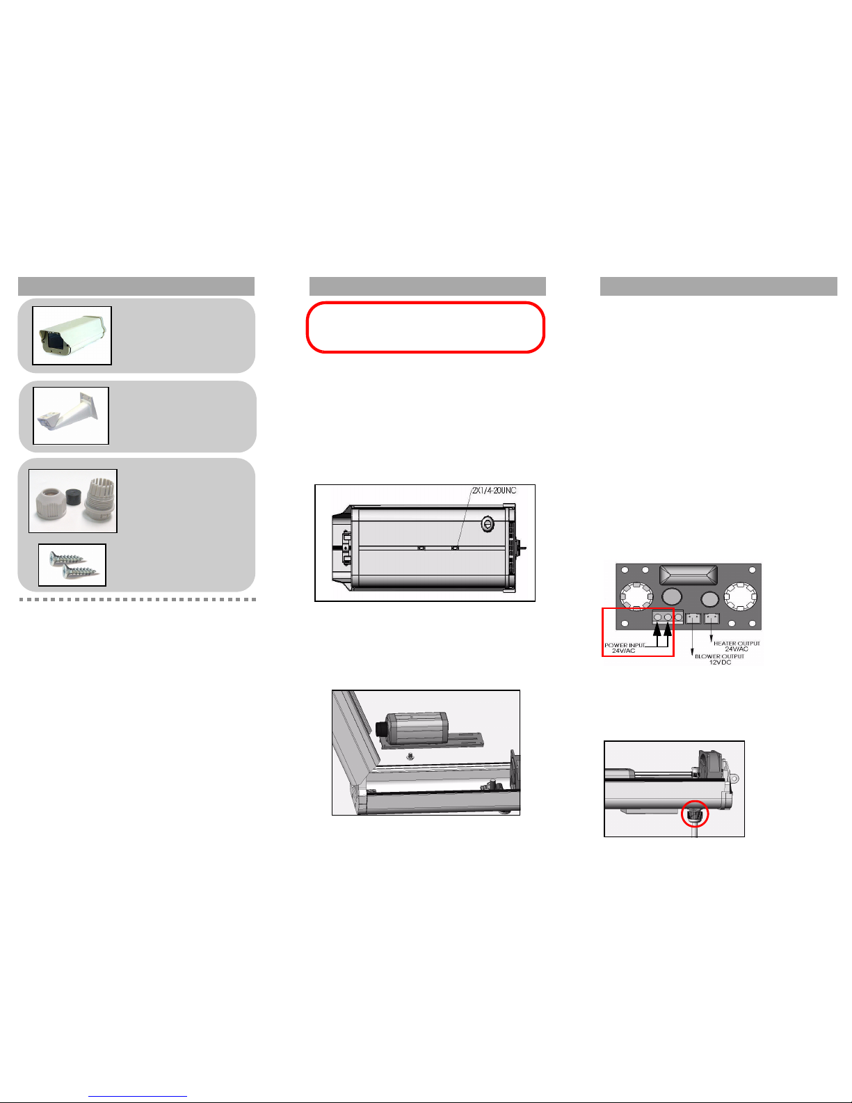
6. ACC1721HB, DAC1721HB models only—Use a
screwdriver (not included) to connect the 24V/AC, non-
polarized wiring to the power input on the thermostat
control board (see Figure 3.0). Tighten the conduit cap
firm
ly to prevent moisture and dust from entering (see
Figure 4.0).
7. Close the enclosure firmly and adjust the bracket
until you have the camera and housing in the
desired position. If desired, use a standard lock
(not included) to lock the housing.
Figure 3.0 Connect wires (x2) to power input terminals
Figure 4.0 Feed cables through duct and tighten cap
Contents Assembling the housing
1 x Screw Kit
1 x Weatherproof Enclosure
To assemble the housing:
1. Mount the wall bracket using the provided screw kit.
Note: Make sure you have drilled any necessary holes
in your mounting surface and run sufficient lengths of
extension cables (not included) for your camera (not
included).
2. Use the included screws to attach the enclosure to the
mounting bracket
.
To install the camera in the housing:
1. Open the enclosure and remove the camera base.
Use the included screws to attach the camera to the
base
.
Figure 1.0 Enclosure base
Figure 2.0 Place camera in enclosure
• Aluminum-coated housing
• Ideal for Indoor/Outdoor use
• Built-in Heater & Blower for use in various
climates*
• Lockable enclosure keeps your CCTV
investement safe**
• Includes metal wall-mount bracket
Accessories:
• Corner Bracket—MNT1721C
• Pole Bracket—MNT1721P
*Heater and Blower on ACC1721HB and DAC1721HB models only.
**Requires optional lock.
1 x Metal Wall-Mount Bracket
Installing the camera
Features:
ATTENTION - Make sure you have tested the camera
(not included) prior to selecting a permanent mounting
location by temporarily connecting the cameras and
cables to the TV,VCR, DVR or Observation System.
1 x Conduit Cap (a)
1 x Rubber Stopper (b)
1 x Conduit Plug (c)
(b)
(c)
(a)
 Loading...