

Printed in KOREA
Instruction Guide
Super DNR High Resolution
Color Camera
Model : CVC8011
Super DNR High Resolution Color Camera
Model : CVC8011
Lorex Technologies Inc.
INFORMATION - This equipment has been tested and found to comply with
limits for a Class A digital device, pursuant to part 15 of the FCC Rules & CE Rules.
These limits are designed to provide reasonable protection against harmful
interference when the equipment is operated in a commercial environment.
This equipment generates, uses, and can radiate radio frequency energy and, if
not installed and used in accordance with the instruction manual, may cause
harmful interference to radio communications.
Operation of this equipment in a residential area is likely to cause harmful
interference in which case the user will be required to correct the interference at
his own expense.
◆
Do NOT use power sources other than those specified.
◆
Do NOT expose this appliance to rain or moisture.
This installation should be made by a qualified service person and
should conform to all local codes.
The lightning flash with an arrowhead symbol, within an equilateral
triangle is intended to alert the user to the presence of uninsulated
dangerous voltage within the product's enclosure that may be of
sufficient magnitude to constitute a risk of electric shock to persons.
The exclamation point within an equilateral triangle is intended to alert
the user to the presence of important operating and maintenance
(servicing) instructions in the literature accompanying the appliance.
WARNING - Changes or modifications not expressly approved by the
manufacturer could void the user's authority to operate the equipment.
CAUTION : To prevent electric shock and risk of fire hazards:
Super DNR High Resolution Color Camera
1

2
Super DNR High Resolution Color Camera Super DNR High Resolution Color Camera
3
■
Contents
Features
Warnings and Precautions
Names and Functions of Parts
Installation
■ Front
■ Top
■ Rear
4
5
9
12
9
10
11
■ Lens
ㆍWhen using a CS-Mount lens (included)
ㆍWhen using a C-Mount lens
■ Connecting to a monitor
■ Connecting to power
12
14
14
Components
8
Camera Operation
15
■ Settings
16
ㆍ LENS
17
ㆍ EXPOSURE
19
ㆍ WHITE BALANCE
22
ㆍDAY/NIGHT
23
ㆍ 3DNR
25
ㆍ SPECIAL
26
ㆍ ADJUST
30
ㆍ RESET
30
ㆍ EXIT
30
- CAM TITLE
- D-EFFECT
- MOTION
- PRIVACY
- SYNC
- LANGUAGE
- RETURN
26
28
28
29
29
30
30
Specifications
33
Limited Warranty
34
Troubleshooting
31

1/3” Super-HAD™II CCD
High Resolution : 560 TV Lines
Min. illumination 0.0006Lux (F1.2, 40 IRE, Sens-Up 256x)
OSD menu control
Internal / Linelock (phase control) function
Electronic day / night function, Sens-Up function (256x)
Motion adaptive digital noise reduction (3D-DNR)
Back light compensation (BLC)
Xtended Dynamic Range (XDR)
8-Zone privacy masking function (polygonal mosaic)
32x digital zoom
Remote OSD menu control (requires optional OSD remote)
Horizontal & vertical image mirroring
Auto sensing DC12V / AC24V
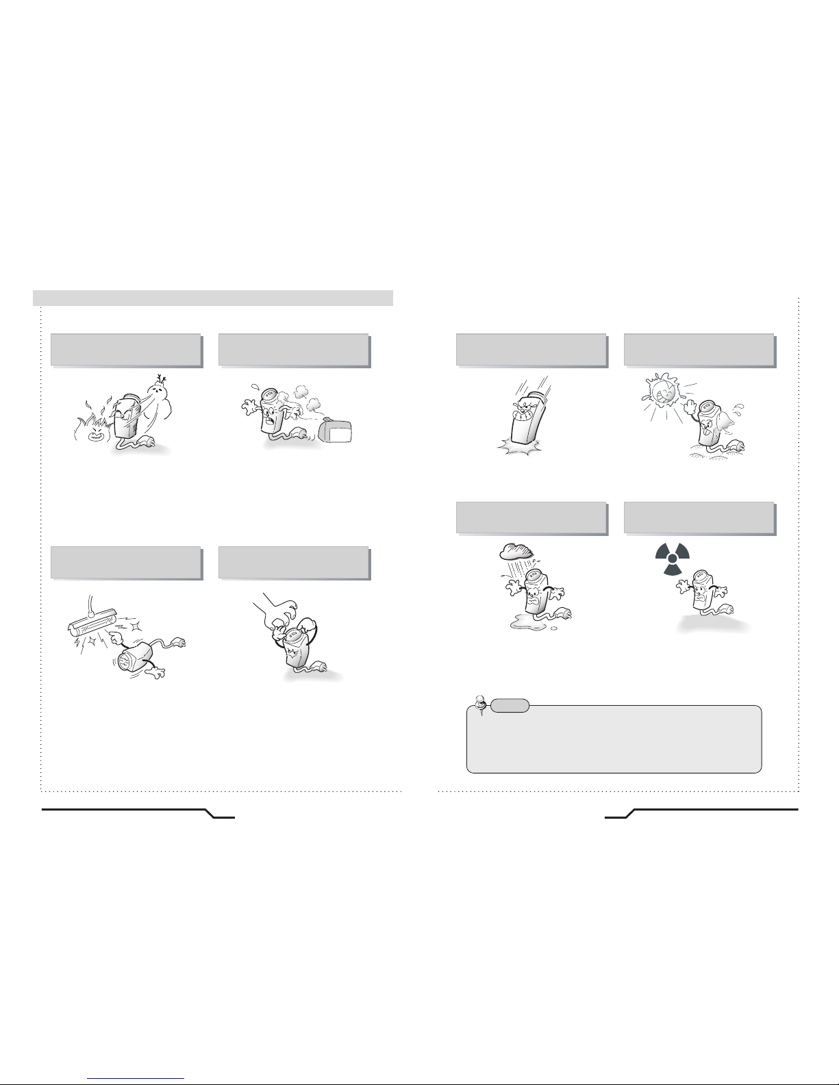
The camera requires periodic inspection.
Contact an authorised technician to carry out the inspection.
Stop using your camera when you find it malfunctioning.
If the camera emits smoke or is unusually hot for a long period,
a fire may be caused.
Do not Install the camera on a surface that can not support it.
If the camera is installed on an inappropriate surface, it may fall
and cause injury.
Do not hold plug with wet hands.
It could cause an electric shock.
Do not dis-assemble the camera.
It may result in an electric shock or other hazards.
Do not use the camera close to a gas or oil leak.
It may result in a fire or other hazards.
4
Super DNR High Resolution Color Camera Super DNR High Resolution Color Camera
5
■
Features
Warning ■
6
Super DNR High Resolution Color Camera Super DNR High Resolution Color Camera
7
■
Precautions
Only use the camera under conditions
where temperatures are between
-10¡C and +50¡C. Be especially
careful to provide ventilation when
operating under high temperatures.
It can cause the image quality to be
poor.
Severe lighting change or flicker can
cause the camera to work improperly.
This is one of the most important parts of
the camera. Be careful not to leave
fingerprints on the lens cover.
Do not install the camera in
extreme temperature conditions.
Do not install or use the camera in an
environment where the humidity is high.
Do not install the camera under
unstable lighting conditions.
Do not touch the front lens of the
camera.
It can cause malfunctions to occur.
If it gets wet, wipe it dry immediately.
Liquids can contain minerals that
corrode the electronic components.
If exposed to radioactivity the CCD
will fail.
It can damage the CCD.
Do not expose the camera to rain
or spill beverage on it.
Do not expose the camera to
radioactivity.
Never keep the camera pointed
directly at strong light.
Do not drop the camera and protect
it to physical shocks.
Note
ㆍIf the camera is exposed to spotlight or object reflecting strong light,
smear or blooming may occur.
ㆍ Please check that the power satisfies the normal specification before
connecting the camera.
8
Super DNR High Resolution Color Camera Super DNR High Resolution Color Camera
9
■
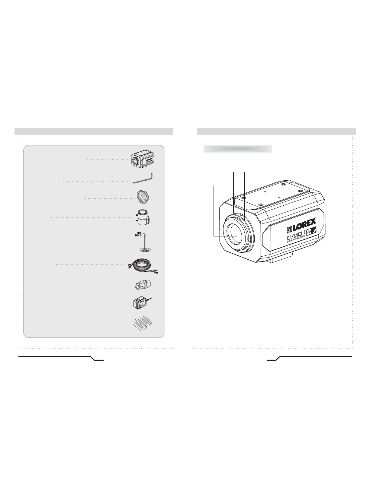
Components
Names and Functions of Parts ■
Front
①
Lens protection cap
Cover the lens when not in use.
②
CS-Mount lens adaptor
Attach the CS-Mount lens here.
③
Back Focus clamp screw
Loosen the clamp screw with a screwdriver before adjusting the Back
Focal length.
1. COLOR BOX CAMERA
2. L-WRENCH
3. C-MOUNT ADAPTOR
9. INSTRUCTION GUIDE
4. LENS
5. MOUNTING BRACKET
6. CABLE
8. ADAPTOR
3.0~8.0mm Auto Iris DC Lens-CS Type
65ft BNC Extension Cable
12V DC 300mA Regulated Power Supply
7. BNC TO RCA ADAPTOR
①
② ③
10
Super DNR High Resolution Color Camera Super DNR High Resolution Color Camera
11
■
Names and Functions of Parts
Names and Functions of Parts
■
IRIS JACK
OSD EXTRA
POWER
DC
VIDEO
SET
VIDEO OUT
AC24V IN
DC12V IN
⑪
⑤ ⑥
⑦
⑧
⑨
⑩
Rear
⑤
Auto iris lens connector
Connection terminal for an auto iris lens.
⑥
Auto iris lens selection switch
Used to change between DC or Video depending upon the type of auto
iris in use.
⑦
OSD Extra
Connect to remote controller (optional - model # ACCRC01) to do camera
set up from the ground instead of on the ladder. Also includes BNC spot
video out to connect to a service monitor.
⑧
Video output terminal
Sendsvideosignals and connectsto the video input terminalof the monitor.
⑨
Power lamp
Lights up when the correct power is supplied to the camera.
⑩
Setting button
●
SET button : Used for the menu display. This button can be used to
confirm settings after changing the value of the selected function or
current conditions.
●
UP & DOWN buttons : Used for selecting items by moving the cursor
up or down on the menu screen.
●
LEFT & RIGHT buttons : Used when changing item values, by moving
the cursor to the left or right on the menu screen.
⑪
Power input terminalLow voltage power connection.
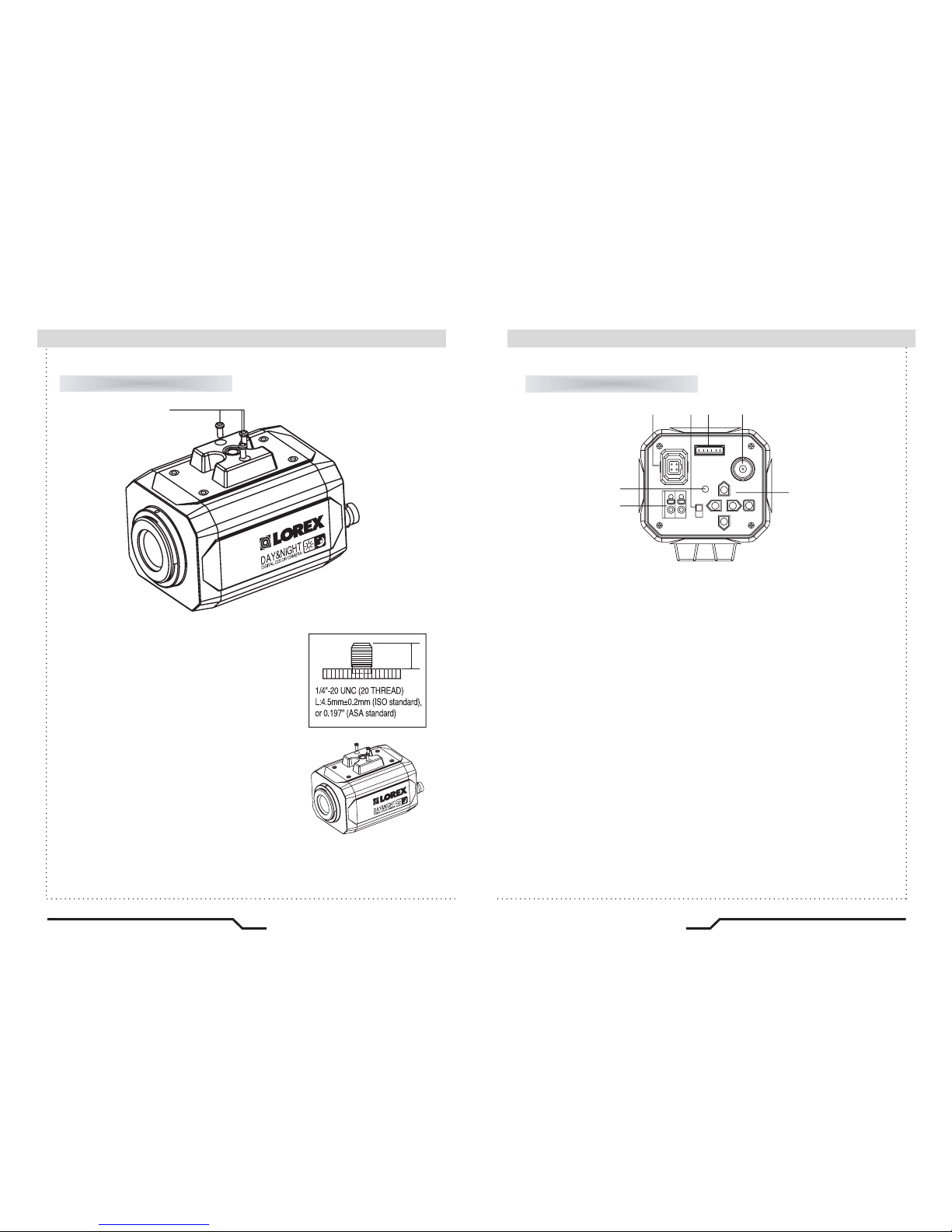
Top
④
Mounting Bracket
Use the screw holes provided when fixing the
camera onto a mounting bracket.Use the clamp
screw as shown in the picture.
※
The mounting bracket canbeattachedto either
the bottom or the top of the camera.
Be careful not to tighten the screws more than
5mm into the body, otherwise serious damage
can occur.
L
④

12
Super DNR High Resolution Color Camera Super DNR High Resolution Color Camera
13
■
Installation
Installation ■
The camera is supplied with a DC varifocal lens. Lenses, such as
auto iris, CS-Mount and C-Mount, are compatible with this camera.
■
Lens
Note
ㆍUsing a DC auto iris lens is recommended to achieve the best
possible results from the camera.
ㆍPlease keep the lens clean.
ㆍForeign objects or fingerprints on the lens will result in inferior image
quality, especially in low light level conditions.
1. Insert the connection plug connected to the auto iris lens cable into
the auto lens connector jack, which is located on the rear of the camera.
2. Set the lens selection switch, located on
the rear of the camera, to either DC or VIDEO,
depending on the type of auto iris lens being
used.
IRIS JACK
OSD EXTRA
POWER
DC
VIDEO
SET
VIDEO OUT
AC24V IN
DC12V IN
Remove the lens protection cap and attach
the CS-Mount lens to the camera by screwing it in
clockwise.
Note
ㆍUse the specified lens connection parts as shown in the picture below.
Using of the wrong sized parts may cause damage
to the inside of the camera or result in poor fitting.
ㆍ
Using a lens which is too heavy affects the balance
of the camera and may cause a malfunction. Please
use a lens that weighs less than 450g.
ㆍSelect Av mode, if possible, when adjusting
the automatic light control (ALC) of an auto lens.
Use of PK mode may cause hunting.
When using a CS-Mount lens (included)
1. Remove the lens protection cap and
attach the C-mount adaptor.
2. Attach the C-Mount lens to the
camera by screwing it in clockwise.
When using a C-Mount lens

■
Installation
Camera Operation ■
14
Super DNR High Resolution Color Camera Super DNR High Resolution Color Camera
15
AC24V IN
DC12V IN
Connect the video output terminal located on the rear of the camera
to the monitor.
ㆍThe connection method varies depending on the type of monitor and
accessories. Please refer to the monitor user manual.
ㆍTurn off the power when connecting.
■
Connecting to a monitor
Check the standard power requirement before connecting to power.
■
Connecting to power
IRIS JACK
OSD EXTRA
POWER
DC
VIDEO
SET
VIDEO OUT
AC24V IN
DC12V IN
AC24V IN
DC12V IN
IRIS JACK
OSD EXTRA
POWER
DC
VIDEO
SET
VIDEO OUT
AC24V IN
DC12V IN
POWER
Dual Power Type
(AC 24V/DC 12V, AC 24V Class2)
DC Power Type (DC 12V, 300mA)
IRIS JACK
OSD EXTRA
POWER
DC
VIDEO
SET
VIDEO OUT
AC24V IN
DC12V IN
POWER
■
Menu
SETUP menu
LENS (selection)
EXIT
ㆍMANUAL ㆍDC/VIDEO
EXPOSURE
ㆍSHUTTER ㆍAGC ㆍSENS-UP
ㆍBLC ㆍHSBLC ㆍD-WDR
WHITE BAL
ㆍATW ㆍAWB ㆍAWC ㆍMANUAL
DAY NIGHT
ㆍCOLOR ㆍAUTO ㆍEXT ㆍB/W
3DNR
ㆍON ㆍOFF
SPECIAL
ㆍCAMTITLE ㆍD-EFFECT ㆍRS-485
ㆍMOTION ㆍPRIVACYㆍLANGUAGE
ㆍSYNC
ㆍFACTORY RESET
RESET
ADJUST
ㆍSHARPNESS ㆍBLUE ㆍRED

SETUP
LENS DC
EXPOSURE
WHITE BAL
ㅡㅡㅡ
SETUP
LENS DC
EXPOSURE
WHITE BAL ㅡㅡㅡ
DAY NIGHT
3DNR
SPECIAL
ADJUST
RESET
EXIT
B/W
ON
3. Set up a selected item by using the Left and Right buttons.
4. To finish and save the settings, select 'EXIT' and press the SET button.
This function is used to adjust the brightness of the screen.
1.
When the SETUP menu screen is displayed on the screen, position
the cursor to point to LENS using the Up and Down buttons.
2. Select the type of lens using the Left and Right buttons.
Select the desired menu
item by using the UP and
DOWN buttons.
Modes can be changed
using the LEFT and
RIGHT buttons.
LENS
Note
• An item with the icon also has sub-menus. To select a sub-menu,
press the SET button.
• An item with the - - - icon has no sub-menus available for selection.
16
Super DNR High Resolution Color Camera Super DNR High Resolution Color Camera
17
■ How to Use the Camera
Settings can be made using the 5 buttons located on the rear of the camera
■
Settings
IRIS JACK
OSD EXTRA
POWER
DC
VIDEO
SET
VIDEO OUT
AC24V IN
DC12V IN
SET
1. Press the SET button
ㆍThe Setup menu is displayed on the monitor screen.
2. Select a menu item using the Up and Down buttons.
ㆍPlace the cursor over a desired item.
SETUP
LENS DC
EXPOSURE
WHITE BAL ㅡㅡㅡ
DAY NIGHT
3DNR
SPECIAL
ADJUST
RESET
EXIT
B/W
ON

■
How to Use the Camera
Note
● DC/VIDEO : Auto Iris Lens selection. (DC lens included)
•
When using an auto iris lens, the setting of the auto iris lens selection
switch, located on the back of the camera, must be on DC or VIDEO
depending on the type of the lens which being used.
(Refer to the picture on page 13)
•
The brightness of the screen can be adjusted in DC mode.
The brightness can be adjusted within the range of 0 ~100.
The optimum level of brightness can be achieved using this adjustment.
• If you press the Set button in "MANUAL LENS", You can Adjust
brightness in EXPOSURE.
•
If you press the Set button in "DC/VIDEO", You can't adjust brightness
in EXPOSURE, Return to "LENS" and adjust brightness.
●
MANUAL : Manual Lens selection.
RETURN
LENS
RET
BRIGHTNESS 40
3. Press the SET button to return to the previous menu.
18
Super DNR High Resolution Color Camera Super DNR High Resolution Color Camera
19
1. When the SETUP menu screen is displayed select EXPOSURE using
the Up and Down buttons.
2. Select the desired mode using the Left and Right buttons.
● SHUTTER
1.The shutter speed is controlled manually.
2. Select 'FLK' mode when flickering occurs on the screen due to an
imbalance between illumination and frequency.
NTSC Model:1/100, PAL Model: 1/120
EXPOSURE
SETUP
LENS DC
EXPOSURE
WHITE BAL ㅡㅡㅡ
DAY NIGHT
3DNR
SPECIAL
ADJUST
RESET
EXIT
B/W
ON
EXPOSURE
SHUTTER
BRIGHTNESS
AGC
SENSE-UP
BLC
D-WDR
RETURN
1/50
ㅡㅡㅡ
MIDDLE
AUTO
OFF
OFF
RET

20
Super DNR High Resolution Color Camera Super DNR High Resolution Color Camera
21
■
How to Use the Camera
● AGC (AUTO GAIN CONTROL)
The higher the gain level, the brighter the screen - but the higher the noise.
- OFF,LOW,MIDDLE,HIGH can be selected
●
SENS-UP
When it is night or dark, the camera automatically detects the light level
and maintains a clear picture if this mode is activated.
- OFF : Deactivates the SENS-UP function.
- AUTO : Activates the SENS-UP function.
●
BLC (Back Light Compensation)
When there is a strong backlight behind the object, clear images of the
background as well as the object can still be obtained by using the
BACKLIGHT function.
SENS-UP
SENS-UP
RETURNX8RET
EXPOSURE
SHUTTER
BRIGHTNESS
AGC
SENSE-UP
BLC
D-WDR
RETURN
1/50
ㅡㅡㅡ
MIDDLE
AUTO
BLC
OFF
RET
BLC ON
BLC OFF
EXPOSURE
SHUTTER
BRIGHTNESS
AGC
SENSE-UP
BLC
D-WDR
RETURN
1/50
ㅡㅡㅡ
MIDDLE
AUTO
OFF
OFF
RET
●BRIGHT LIGHT COMPENSATION (HSBLC)
The CVC8011 is equipped with Bright Light Compensation technology
(HSBLC) which effectively blocks strong light sources (such as car
headlights) by digitally masking them. The result is a clearer and
brighter view of the areas surrounding the strong light source.
●XTENDED DYNAMIC RANGE (D-WDR)
In strong backlight or high contrast scenes, most conventional CCTV
cameras lose details in the darker portions of the image. The CVC8011
compensates for this loss in image detail by utilizing Xtended Dynamic
Range technology (D-WDR) to brighten up darker areas of the image
to regain definition and detail.
●
RETURN : Saves the FUNCTION menu and returns to the SETUP menu.
HSBLC OFFHSBLC ON
HSBLC MASKING
3. Select the desired mode using the Left and Right buttons and press
the SET button.
BLC
GAIN
DEFAULT
LEFT/RIGHT
WIDTH
TOP/BOTTON
HEIGHT
RETURN
MIDDLE
2
4
3
3
RET
HSBLC
LEVEL
DEFAULT
LEFT/RIGHT
WIDTH
TOP/BOTTON
HEIGHT
RETURN
8
2
4
3
3
RET

SETUP
LENS DC
EXPOSURE
WHITE BAL ATW
DAY NIGHT
3DNR
SPECIAL
B/W
ON
WHITE BAL MANUAL
BLUE
RED
RETURN
21
15
RET
Note
•
Under the following conditions White Balance may not work properly.
In such cases, select the AWC mode.
①When the color temperature of the subject environment has a very
high temperature range (e.g. clear sky, or sunset)
②When the ambient illumination of the subject is low.
③
If the camera is directed toward a fluorescent light, or is installed in
a place where illumination changes dramatically, the White Balance
operation may become unstable.
Pictures can be displayed in either color or black and white.
1. When the SETUP menu screen is displayed, select 'DAY/NIGHT' using
the Up and Down buttons.
DAY/NIGHT
22
Super DNR High Resolution Color Camera Super DNR High Resolution Color Camera
23
■
How to Use the Camera
WHITE BALANCE
Use the White Balance function to adjust the screen colors.
1.
Position the cursor to point to WHITE BAL on the SETUP menu screen,
select using the Up and Down buttons.
2. Select the desired mode using the Left and Right buttons.
●
ATW(Auto Tracking White Balance) : This mode can be used within
the color temperature range 2,000˚K ~ 9500˚K
●
AWB(Automatic White Balance) : This mode can be used within the
color temperature range 1,800˚K ~ 11,000˚K
●
AWC SET : To obtain the optimum state under the current luminance
levels, direct the camera to point toward a sheet of white paper
and press the SET button. If the environment changes, including
the light source, the white balance will require re-adjustment.
●MANUAL : The manual adjustment mode enables finer adjustment.
Select ATW or AWB first then change to manual adjustment mode
and press the SET button. Set the appropriate color temperature
then increase / decrease the red and blue colour values and monitor
the color changes of the object.
SETUP
LENS DC
EXPOSURE
WHITE BAL ATW
DAY NIGHT
3DNR
SPECIAL
ADJUST
RESET
EXIT
B/W
ON

■
How to Use the Camera
Note
• When using a Video Auto Iris Lens, if the lens level is too low,
automatic switching between Color and Black & White may not occur.
• If you press the Set button in "AUTO", AGC is disabled.
• The camera focus will "shift" marginally under infrared illumination
at night. Always use an IR Corrective extra-low dispersion lens to
obtain sharp pictures in color and monochrome.
2. Select the desired mode using the Left and Right buttons.
●COLOR : The color mode is selected as the default, and the camera
does not change automatically.
●AUTO : This camera has a function which automatically changes to
the appropriate mode dependant on lighting levels. COLOR mode
is selected during daylight and B/W mode at night time.
(Set START LEVEL and END LEVEL manually, as appropriate environment.)
●
EXTERN : This mode allows the application of a filter to external signals.
●B/W : Discards the color information and displays in black and white.
DAY NIGHT AUTO
DELAY
S-LEVEL
E-LEVEL
RETURN
5
55
65
RET
24
Super DNR High Resolution Color Camera Super DNR High Resolution Color Camera
25
Note
• When adjusting the noise reduction level in DNR mode, remember
that the higher the level is set, the greater the reduction in noise level,
but it also increases the possibility of ghosting.
3D Digital Noise Reduction (3D-DNR)
3DNR
DELAY
RETURN
50
RET
This function reduces the background noise in a low luminance environment.
1.
When the SETUP menu screen is displayed, select 'DNR' using the
Up and Down buttons.
2. Select a desired mode using the Left and Right buttons.
● OFF : Deactivates DNR. Noise is not reduced.
● ON : Activates DNR so that noise is reduced.
3.
Set the DNR mode to 'ON' and press the SET button. The noise reduction
level can now be adjusted.
SETUP
LENS DC
EXPOSURE
WHITE BAL ㅡㅡㅡ
DAY NIGHT
3DNR
SPECIAL
ADJUST
RESET
EXIT
B/W
ON

26
Super DNR High Resolution Color Camera Super DNR High Resolution Color Camera
27
■
How to Use the Camera
SPECIAL
1. When the SETUP menu screen is displayed, select 'SPECIAL' using
the Up and Down buttons.
2. Select the desired mode using the Left and Right buttons.
●CAM TITLE: If a title is entered, the title appears on the monitor.
①
When the SPECIAL menu screen is displayed, use the Up and Down
buttons to point the cursor to ' CAM TITLE '.
②Set to 'ON' using the Left and Right buttons.
SETUP
LENS DC
EXPOSURE
WHITE BAL ㅡㅡㅡ
DAY NIGHT
3DNR
SPECIAL
ADJUST
RESET
EXIT
B/W
ON
SPECIAL
CAM TITLE
D-EFFECT
RS485
MOTION
PRIVACY
SYNC
LANGUAGE
RETURN
OFF
ON
OFF
INT
ENGLISH
RET
Note
• When the CAM TITLE menu is 'OFF', no title will be displayed on the
monitor screen even if one has been entered.
Note
•
If the cursor is moved to CLR and the SET button pressed, all letters
are deleted. To edit a letter, change the cursor to the bottom left arrow
and press the SET button. Move the cursor over the letter to be edited,
move the cursor to the letter to be inserted and then press the SET button.
③Press the SET button.
④Use the 4 directional buttons to move to a chara cter, and select
it by pressing the SET button. Repeat this action to enter multiple
characters. Up to 15 alphanumeric characters can be used.
SPECIAL
CAM TITLE
D-EFFECT
RS485
MOTION
PRIVACY
SYNC
LANGUAGE
RETURN
OFF
ON
OFF
INT
ENGLISH
RET
CAM LITLE
0123456789
BCDEFGHIJK
LMNOPQRSTUV
WXYZ▶( )
 ̄-_
■/=&:~,.
CLR POS END
HAWK

28
Super DNR High Resolution Color Camera Super DNR High Resolution Color Camera
29
■
How to Use the Camera
- FREEZE : View still pictures.
- MIRROR : MIRROR,V-FLIP,ROTATE can be selected.
-
D-ZOOM : OFF(X1), ON(X2 to X32) can be selected.
-
GAMMA : Users can change the gamma settting in 0.5 steps,
between 0 and 1.0
-
NEG.IMAGE : NEGATIVE IMAGE or POSITIVE IMAGE can be selected.
●MOTION DETECTION:
This product has a feature that allows you to observe movements
of objects in 4 different areas on the screen, and the green shape
appear. on the screen when movement is detected; hence a single
individual can conduct supervision efficiently. The camera detects
an object's movement by sensing disparity of outline, and level of
brightness and color.
● D-EFFECT
D-EFFECT
FREEZE
MIRROR
D-ZOOM
GAMMA
NEG.IMAGE
RETURN
OFF
OFF
OFF
0.45
OFF
RET
MOTION
AREA SELECT
AREA DISPLAY
LEFT/RIGHT
WIDTH
TOP/BOTTON
HEIGHT
SENSITIVITY
MOTION VIEW
RETURN
AREA1
ON
13
32
4
24
34
OFF
RET
● PRIVACY : Hide an area so that it is not displayed on the monitor.
Set up using the 4 directional buttons.
- AREA SELECT : Up to 8 areas are selectable.
-
AREA DISPLAY : Determines whether to use the area selected in the
AREA SEL, and the size and position of the area.
● SYNC : In areas where the supply is 60Hz, synchronisation function
(Line-Lock),multiple cameras using the power synchronisation function
(Line-Lock),without using a synchronisation signal generator.
- INT : Internal Synchronisation Type
- L/L : Power Synchronisation Type, Line-lock
ㆍPress the SET button.
ㆍSelect a phase between 0 and 359.
- COLOR : Determine area color. Select any colors of 16.
-
RETURN : Select this to save the PRIVACY menu settings and
return to the SPECIAL menu.
ㆍ
Please select the area you wish to observe from the 4 areas in
AREA SELECT mode.
ㆍPlease select ON mode for the chosen area.
ㆍPlease adjust the size of the area to be observed by using the
LEFT/RIGHT, WIDTH,TOP/BOTTOM,HEIGHT button.
ㆍPlease adjust the level of observation by using SENSITIVITY mode.
ㆍ
Please press the RETURN button to save the changes and complete
the setting.
MOTION
AREA SELECT
AREA DISPLAY
LEFT/RIGHT
WIDTH
TOP/BOTTON
HEIGHT
COLOR
RETURN
AREA1
ON
8
16
8
16
0
RET
SYNC
PHASE
RETURN
0
RET

30
Super DNR High Resolution Color Camera Super DNR High Resolution Color Camera
31
■
How to Use the Camera
ADJUST
RESET
●LANGUAGE
Users can select their preferred language for the OSD menu from
either, English, Korean, Chinese (Big5), Chinese (Simplified) or
Japanese.
●RETURN : Select this to save the SPECIAL menu settings and
return to the SET UP menu.
RESET : Resets the camera settings to the factory defaults.
EXIT
Press the SET button in the EXIT menu to save the current settings and
exit the SET menu.
●
Sharpness : The sharpness of the image can be adjusted using the
left and right buttons. (32 steps)
●
BLUE : The blue color can be increased/decreased using the left
and right buttons. (100 steps)
●
RED : The red color can be increased/decreased using the left
and right buttons. (100 steps)
ADJUST
SHARPNESS
BLUE
RED
RETURN
17
88
88
RET
Troubleshooting ■
If you have trouble operating your camera, refer to the following table.
If the guidelines do not enable you to solve the problem, contact an
authorized technician.
Problem
Nothing appears on
the screen.
The image on the
screen is dim.
• Check the power connections.
• Check the VIDEO signal line connection.
•
Make sure the lens is clean. Clean the lens with a
soft clean lint free cloth.
• Adjust the monitor contrast & brightness controls.
•
Re-position the camera if necessary.
The image on the
screen is dark.
• Adjust the contrast control of the monitor.
•
If you have an intermediate device, set the 75Ω/ Hi-z
properly.
The camera is not working
properly, and the surface
of the camera is hot.
• Check that an appropriate power source is
connected to the camera.
The DAY/NIGHT menu
does not work.
• Check that AGC in the EXPOSURE menu is set
to 'OFF'.
The SENS-UP function
does not work.
• Check that AGC in the EXPOSURE menu is not
set to 'OFF'.
• Check that SHUTTER in the EXPOSURE menu
is not set to 'FLK' or 'MANUAL'.
Solution

■ Troubleshooting
32
Super DNR High Resolution Color Camera Super DNR High Resolution Color Camera
33
Problem
The Motion Detection
function does not
work.
Color is not correct.
• Check that MOTION DEF of SPECIAL SETUP
menu is 'OFF'.
• Check the setting of WHITE BAL SETUP menu .
The screen flickers
continually.
• Check that direction of camera turns toward the
Sun.
Solution
Specifications ■
O.S.D
Lens Mount
Operating Temperature / Humidity
Storing Temperature / Humidity
Dimension
Weight
English, Korean, Chinese (Big5)
Chinese (Simplified) or Japanese
NTSC
CCD
Sync
Power Source
E
L
E
C
T
R
I
C
A
L
SONY 1/3" Super HAD High Sensitivity Color CCD
811(H) x 508(V)
768(H) x 494(V)
2:1 Interlace
Internal / Line Lock
Horizontal : 15.734 KHz, Vertical:59.94 Hz
CS Mount (Easy Focus type)
(C Mount is mountable by using adaptor)
OFF / BLC / HSBLC
560 TV Lines
52 dB (AGC Off, Weight ON)
0.15Lux(40IRE Color), 0.0006Lux(40IRE Sense-upX256) at F1.2
ATW / AWB / AWC / Manual
1/60 ~ 1/120,000 sec
AUTO / OFF (Selectable x2 ~ x256)
LOW / MIDDLE / HIGH / OFF
ON / OFF
ON / OFF (4 Zone, ALARM Output)
ON / OFF (8 Zones)
ON / OFF
ON / OFF
ON / OFF
ON / OFF (Level Adjustable)
DC / Video
COLOR / Black& White / AUTO / EXT
ON(x32) / OFF
-10˚C to + 50˚C / 30% to 80% RH
-20˚C to + 60˚C / 20% to 90% RH
63.7(W) × 55.7(H) × 87.4(D)mm
Appro. 240g
Size
Total Pixels
Effective Pixels
Scanning System
Synchronisation
Frequency
Back-light Comp.
Resolution
S/N (Y signal)
Min. Illumination
White Balance
Electronic Shutter
Speed
Sens-up
Gain Control
DNR
Motion Detection
PRIVACY
V-REV
H-REV
FREEZE
SHARPNESS
IRIS Control
Day & Night
Digital Zoom
DC12V Only (Max.160mA)
AC24V / DC12V (Max.170mA / Max.260mA)

34
Super DNR High Resolution Color Camera Super DNR High Resolution Color Camera
35
■ Limited Warranty
LOREX PRODUCT LIMITED WARRANTY
Lorex warrants, to the original retail purchaser only (the "Purchaser"), that this item (the "Product")
if properly used and installed, and where applicable, the CD-ROM on which the accompanying software
is provided, is free from manufacturing defects in material and workmanship, provided the Product is
used in normal conditions and is installed and used in strict accordance with the instructions contained.
This warranty shall be for the following warranty periods (the "Warranty Period"), commencing on the
date the Purchaser buys the Product at retail in an unused condition.
Parts and Labor : 1 year (Warranted parts do not include Bulbs, LED's and Batteries)
Lorex's obligations under this warranty shall be limited to
ㆍThe repair and or replacement of the product by means of hardware and/or software (at option of Lorex);
ㆍThe replacement of any warranted parts found by Lorex to be defective in the Product or, in Lorex's
sole discretion, the replacement of the Product found be Lorex to be defective.
ㆍIf Lorex is unable to repair or replace the Product or CD-ROM, refund the then-current value of the Product.
Any replacement parts furnished by Lorex in connection with this warranty shall be warranted to the
Purchaser for a period equal to the un expired portion of Warranty Period for the Product.
Warranty Exclusions
This warranty does not apply to Bulbs, LED's and Batteries supplied with or forming part of the product.
This warranty is invalidated if other than Lorex accessories are or have been used in or in connection with the
Product or in any modification or repair is made to the Product by other than a service depot authorized by Lorex.
This warranty does not apply to defects or damages arising by use of the Product in other than normal
(including normal atmospheric, moisture and humidity) conditions or by installation or use of the Product
other than in strict accordance with the instructions contained in the Product's Owner's Manual. This warranty
does not apply to defects in or damages to the Product caused by (i) negligent use of the Product,
(ii) misuse, abuse, neglect, alteration, repair or improper installation of the Product, (iii) electrical short
circuits or transients, (iv) Purchaser usage not in accordance with product installation, (v) use of replacement
parts not supplied by Lorex (vi) improper Product maintenance, or (viii) accident, fire, flood or other Acts of God.
This warranty does not cover the performance or functionality of any computer software included in the
package with the Product. This warranty only covers defects in the CD-ROM media such as a broken or
a defect in the CD-ROM that would prevent the CD-ROM from being read by your personal computer's
CD-ROM drive. Lorex makes no warranty that the software provided with the Product will function without
interruption or otherwise be free of anomalies, errors or 'Bugs'. Lorex makes no warranty with regard to
any software provided with the Product unless specifically set forth otherwise in a license agreement
accompanying such software. This warranty does not cover any costs relating to removal or replacement
of any Product, CD-ROM, or software installed on your computer.
Lorex reserves the right to make changes in design or to make additions to or improvements in its products
without incurring any obligation to modify any product which has already been manufactured. Lorex will
make every effort to provide updates and fixes to its software via its website. This warranty does not cover
any alteration or damage to any other software that may be or may become resident on the users system
as a result of installing the software provided. This warranty is in lieu of other warranties, express or implied,
and Lorex neither assumes nor authorizes any person to assume for it any other obligation or liability in
correction with the sale or service of the Product. In no event shall Lorex be liable for any special or
consequential damages arising from the use of the Product or arising from the malfunctioning or non-functioning
of the Product, or for any delay in the performance of this warranty due to any cause beyond its control.
This warranty shall not apply to the appearance or accessory items including, but not limited to cabinets,
cabinet parts, knobs etc., and the uncrating, setup, installation or the removal and reinstallation of products
after repair.
Lorex does not make any claims or warranties of any kind whatsoever regarding the Product's potential,
ability or effectiveness to prevent minimize, or in any way affect personal or property damage or injury.
Lorex is not responsible for any personal damage, loss or theft related to the Product or to its use for any harm,
whether physical or mental related thereto. Any and all claims or statements, whether written or verbal, by
salespeople, retailers, dealers or distributors to the contrary are not authorized by Lorex, and do not affect
this provision of this warranty.
Lorex's responsibility under this, or any other warranty, implied or expressed, is limited to repair, replacement
or refund, as set forth above. These remedies are the sole and exclusive remedies for any breach of
warranty. Lorex is not responsible for direct, special, incidental, or consequential damages resulting
from any breach of warranty or under any other legal theory including but not limited to, loss profits,
downtime, goodwill, damage to or replacement of equipment and property and any costs of recovering,
reprogramming or reproducing any program or data stored in or used with a system containing the
Product CD-ROM or accompanying software.
Lorex does not warrant that the software will operate with any other software except that which is indicated.
Lorex cannot be responsible for characteristics of third party hardware or software which may effect
the operation of the software included.
The purchaser may have other rights under state, provincial, or federal laws and where the whole or
part of any item of this warranty is prohibited by such laws, it shall be deemed null and void, but the
remainder of the warranty shall remain in effect.
All expressed and implied warranties are limited in duration to the limited warranty period. No warranties
apply after that period. Some states do not allow limitation on how long an implied warranty lasts, so
this limitation may not apply to you. Some states do not allow the exclusion or limitation of incidental
or consequential damages, so the above warranty may not apply to you. This limited warranty gives
you specific legal rights and you may also have other rights that vary from state to state.
Obtaining Service
In order to obtain service, please make sure that you have registered your product on-line (www.lorexcctv.com)
in the warranty registration section. Should the Product require service under this warranty, the Purchaser
must provide Lorex with a copy of his/ her original, dated bill of sale; receipt or invoice, failing which Lorex
will not perform any of its obligations under this warranty. If you return the Product and/or CD-ROM
to Lorex, you must assume the risk of damage or loss during shipment. You must use the original packaging
or the equivalent, and you must pay postage.
To claim on this warranty, proceed with the following steps.
1 Pack the Product in a well-padded sturdy carton.
2. i). If the unit was purchased in the United States proceed as follows :
a. Please contact our customer service department to obtain a return authorization number.
b. Return the unit to : Lorex Returns
c/o Russell Farrow
15 Lawrence Bell Drive, Amherst, NY 14221
ii). If the unit was purchased in Canada proceed as follows :
a. Please contact our customer service department to obtain a return authorization number.
b. Return the unit to : Lorex Service Center.
250 Royal Crest Court, Markham, Ont. L3R 3S1
iii) If the unit was purchased in Europe please visit:
www.lorexinternational.com for return instructions.
TOLL FREE CUSTOMER SUPPORT
North America: 1-888-42-LOREX (1-888-425-6739)
Local: 905-940-5355
International: 800-42-LOREX 0 (800-425-67390)
www.lorexcctv.com
Always use discretion when installing video and/or audio surveillance equipment especially when there is
perceived privacy. Inquire regarding federal, state and/or local regulations applicable to the lawful installation
of video and or audio recording or surveillance. Party consent may be required.

36
Super DNR High Resolution Color Camera Super DNR High Resolution Color Camera
37
■
Limited Warranty
GARANTIE LIMITÉE DES PRODUITS LOREX
Lorex garantit à l'acheteur original (ci-après désigné comme étant "l'acheteur") dans un magasin au
détail seulement, et que ce produit (ci-après désigné comme étant le "produit"), s'il est installé correctement
et - s’il y a lieu - utilisé conformément aux instructions ci-incluses, et le disque CDROM qui comporte
le logiciel, seront libres de tout défaut de fabrication, tant dans les pièces que la main-d'oeuvre, pourvu
que le produit soit utilisé dans des conditions normales et installé et utilisé strictement selon les instructions
incluses dans le guide qui l'accompagne.
Cette garantie couvrira la période mentionnée ci-dessous (ci-après désignée comme étant la "période
de garantie"), commençant le jour où l'acheteur se procure le produit à l'état neuf dans un magasin au détail.
Pièces et main-d'oeuvre : 1 année (les pièces couvertes n'incluent pas les
ampoules, voyants à DEL ni les piles).
Les obligations de Lorex selon les termes de cette garantie se limitent exclusivement aux points suivants :
ㆍLorex se réserve le droit de réparer ou de remplacer, sa seule discrétion, le logiciel et/ou le matériel.
ㆍLe remplacement des pièces sous garantie que Lorex estime être défectueuses dans le produit ou
le disque CD-ROM ou, à sa seule discrétion, le remplacement du produit jugé défectueux.
ㆍSi Lorex ne peut réparer ni remplacer le produit ou le disque CD-ROM, rembourser la valeur monétaire
du produit ou du disque CD-ROM en cours au moment de l'achat.
Toutes les pièces remplacées par Lorex seront couvertes pendant la période résiduelle de la garantie
dudit produit.
Exclusions de la garantie
Pour obtenir du service, veuillez vous assurer que vous avez inscrit votre produit en ligne (www.lorexcctv.com)
dans la section d'abonnement à la garantie. Cette garantie ne couvre pas les ampoules, voyants à DEL
ni les piles incluses avec le produit ou faisant partie de celui-ci.
Cette garantie deviendra nulle si des accessoires autres que ceux vendus ou distribués par Lorex
sont utilisés ou ont été utilisés conjointement avec le produit ou si des modifications ou des réparations
ont été effectuées au produit par une entité autre qu'un centre de service autorisé par Lorex.
Cette garantie ne s'applique pas aux défauts ni aux dommages survenus suite à une utilisation anormale
du produit (incluant des conditions atmosphériques et des taux d'humidité anormaux) ou suite à une
installation ou une utilisation du produit autre que celle décrite dans le guide accompagnant le produit.
Cette garantie ne s'applique pas aux défauts ni aux dommages causés au produit suite à (i) une utilisation
insouciante du produit, (ii) mauvaise utilisation, abus, négligence, modification ou mauvaise installation
du produit, (iii) court-circuits ou transitoires électriques, (iv) tout usage de l'acheteur qui ne correspond
pas à l'installation prescrite du produit, (v) l'utilisation de pièces non fournies par Lorex, (vi) un entretien
inadéquat du produit, ou (vii) tout accident, incendie, inondation ou autres désastres naturels.
Cette garantie ne couvre pas la performance ni la fonctionnalité de tout logiciel informatique inclus avec
le produit. Cette garantie ne couvre pas les défauts que pourrait contenir le support optique (disque CD-ROM)
ou magnétique (disquette), tel qu'un CD-ROM brisé ou comportant un défaut qui l'empêcherait d'être
lu adéquatement par le lecteur de disque de votre ordinateur. Lorex ne garantit pas que le logiciel fourni
avec le produit fonctionnera sans interruption ni qu'il sera libre de tout défaut, d'erreurs ou de 'bogues'.
Lorex ne garantit pas le logiciel inclus à moins que cela ne le soit mentionné spécifiquement dans l'entente
de la licence incluse avec le produit. Cette garantie ne couvre pas les frais se rapportant à l'enlèvement
ni à la réinsertion de tout produit, logiciel, périphérique ou disque CD-ROM installé sur votre ordinateur.
Lorex se réserve le droit de modifier la conception ou d'apporter des ajouts ou des améliorations à
ses produits, sans obligation de sa part de modifier les produits déjà fabriqués. Lorex fera tout en son
pouvoir pour fournir des améliorations et des réparations à son logiciel via son site web.
Cette garantie ne couvre pas les altérations ni les dommages effectues tout autre logiciel, ni les bogues
pouvant résider de faıon permanente sur le système de l'utilisateur suite l'installation du logiciel ci-inclus.
Cette garantie a préséance sur toutes les autres garanties tacites ou explicites, incluant la garantie en qualité
loyale et marchande et les aptitudes visant toute autre obligation ou responsabilité de la part de Lorex, et par les
présentes, Lorex n’autorise aucune personne ni entité à assumer pour elle nulle autre responsabilité en rapport
avec la vente de ce produit. Lorex ne sera pas tenue responsable, en aucune circonstance, des dommagesintérêts
directs ou indirects survenant de l'utilisation du produit ou suite au mauvais fonctionnement ou à l'absence
de fonctionnement dudit produit, ainsi que pour tout délai dans l'exécution de cette garantie suite à des
circonstances hors du contrôle de Lorex.
Lorex ne garantit d’aucune manière l'apparence extérieure du produit, ni les pièces ou accessoires incluant,
mais ne s'y limitant pas, le boîtier, les pièces du boîtier, les boutons, etc., ainsi que le déballage, l'installation,
l'enlèvement et la réinstallation du produit après une réparation.
Lorex ne garantit pas et ne fait aucune revendication en ce qui a trait au potentiel, à la capacité ou l'efficacité
de prévenir, réduire ou d'une façon quelconque, d'influer sur les dommages à la propriété privée ou sur
les blessures corporelles. Lorex ne sera pas tenue responsable des blessures corporelles, dommages
à la propriété personnelle, perte ni au vol se rapportant de près ou de loin au produit ou son usage dans
un cadre malveillant, qu'il soit physique ou mental. Lorex n'autorise aucunement les représentants, détaillants
ou grossistes, à faire des revendications ou des énoncés de la part de Lorex, tant par voie écrite que verbale
et ces énoncés n'influent d'aucune manière sur les clauses de cette garantie.
La seule responsabilité de Lorex, selon les termes de cette garantie, qu'ils soient tacites ou explicites,
se limite à une réparation, un remplacement ou un remboursement, selon les clauses décrites dans les
présentes. Ces recours constituent les seuls auxquels a droit l'acheteur pour les bris des clauses de la
garantie. Lorex ne sera pas responsable des dommages-intérêts spéciaux, directs ou indirects, qui résulteraient
d'un bris des clauses de cette garantie ou de toute autre convention législative, incluant mais ne s'y limitant
pas, les pertes de profits, pannes de courant immobilisant des équipements, la valeur ajoutée des biens
incorporels, les dommages effectués au produit et à la propriété ou les coûts reliés à leur remplacement,
ainsi que les frais de recouvrement, reprogrammation ou reproduction d'un programme ou des données
stockées dans un système contenant le disque CD-ROM du produit ou le logiciel qui accompagne celui-ci.
L'acheteur peut bénéficier de certains droits provinciaux ou fédéraux additionnels et toute clause de cette garantie
qui soit prohibée par de telles lois sera jugée nulle et sans effet mais les autres clauses demeureront en vigueur.
Lorex ne garantit pas que ce logiciel fonctionnera conjointement avec tout autre logiciel ou suite logicielle,
moins que cela ne soit indique. Lorex ne sera pas tenue responsable des caractéristiques ni des fonctions du
matériel ou des logiciels d'un tiers pouvant entrer en conflit avec le fonctionnement du logiciel ci-inclus.
Toutes les garanties tacites ou explicites se limitent à la durée de la garantie limitée. Aucune garantie ne sera
applicable après cette période de temps. Certains états ou provinces ne permettent pas de restrictions en ce
qui a trait aux termes d’une garantie tacite, ni d’exclusions aux dommages-intérêts directs ou indirects et il se
peut que ces restrictions ne s'appliquent pas à vous. Cette garantie donne à l’acheteur original des droits
spécifiques et il se peut que d’autres droits, variant d’un état ou d’une province à l’autre, puissent lui être conférés.
Obtention du service
Si l'acheteur a besoin de service pour son produit, selon les termes de cette garantie limitée, il doit fournir à
Lorex une copie de la facture d'achat affichant clairement la date et l'endroit où le produit a été acheté. Sans
cette preuve d'achat, Lorex ne sera pas dans l'obligation de remplir ses obligations envers l'acheteur. Si vous
retournez le produit et/ou le disque CD-ROM à Lorex, vous devez assumer le risque que ceux-ci soient endommagés
ou perdus au cours de l'expédition. Vous devez emballer le produit dans sa boîte originale ou un emballage
adéquat et vous devez défrayer les coûts d'expédition à l'une des adresses mentionnées ci-dessous.
Pour bénéficier du service sous garantie, vous devez suivre les étapes ci-dessous :
1. Emballez le produit dans une boîte solide et remplie de matériau d'expédition.
2. i) Si l'appareil a été acheté aux États-Unis, suivez ces étapes-ci :
a. Veuillez contacter notre département de service à la clientèle pour obtenir un numéro d'autorisation
pour le retour.
b. Retournez le produit à : Lorex Returns c/o Russell Farrow 15 Lawrence Bell Drive, Amherst, NY 14221
ii) Si l'appareil a été acheté au Canada, suivez ces étapes-ci :
a. Veuillez contacter notre département de service à la clientèle pour obtenir un numéro d'autorisation
pour le retour.
b. Retournez le produit à : Lorex Customer Service 250 Royal Crest Court, Markham, ON L3R 3S1
iii) Si l'unité a été achetée dans Europe veuillez visiter : www.lorexinternational.com pour les instructions de retour
COMPOSEZ LA LIGNE D’ASSISTANCE SANS FRAIS AUS CONOMMATEURS:
L'Amérique du nord: 1-888-42-LOREX (1-888-425-6739)
Local : 905-940-5355
International : 800-42-LOREX 0 (800-425-67390)
Soyez toujours très discret lorsque vous installez des systèmes de surveillance, surtout dans les endroits plus
retirés. Informezvous au sujet des lois et règlements municipaux, provinciaux ou fédéraux qui s’appliquent à
l’installation d’appareils de surveillance audio et vidéo. Il se peut que le consentement de la partie surveillée
soit exigé.

Lorex no hace ninguna de cada declaración ni garantía de ninguna clase con respecto al potencial,
capacidad o eficacia del Producto para evitar, minimizar o en alguna forma afectar a los daños o lesiones
personales o a la propiedad. Lorex no es responsable por ningún daño personal, siniestro o robo relacionado
con el Producto o a su uso para cualquier daño, sea físico o mental relacionado con el mismo. Cualquier
afirmación o declaración, sea escrita o verbal, hecha por vendedores, minoristas o distribuidores en
sentido contrario no es autorizada por Lorex y no afecta esta disposición de esta garantía.
La responsabilidad de Lorex según ésta o cualquier otra garantía, implícita o explícita, está limitada a
la reparación, reemplazo o reembolso, como se establece anteriormente. Estas compensaciones son
el único y exclusivo remedio por cualquier incumplimiento de garantía. Lorex no es responsable por
daños y perjuicios directos, especiales, incidentes, o consecuentes resultantes de algún incumplimiento
de garantía o bajo cualquier otra teoría legal, incluyendo pero sin estar limitada a: pérdida de utilidades,
paralización, plusvalía, daños o reemplazo de equipos y propiedad y cualquier costo de recuperar,
reprogramar o reproducir cualquier programa o datos almacenados o usados con un sistema que contenga
el CD-ROM del Producto o el software que lo acompaña.
Lorex no garantiza que el software operará con ningún otro software excepto con el que se indica.
Lorex no puede ser responsable de las características de hardware o software de terceras personas
que puedan afectar la operación del software incluido.
El comprador puede tener otros derechos de acuerdo con las leyes federales, provinciales o estatales
y cuando toda esta garantía o parte de la misma sea prohibida por dichas leyes, será considerada nula,
pero el resto de la garantía permanecerá vigente.
Todas las garantías expresadas e implícitas están limitadas en duración al período de garantía limitada.
Ninguna garantía se aplicará después de dicho período. Algunos estados no permiten limitación a la
duración de una garantía implícita, de modo que esta limitación puede no serle de aplicación. Algunos
estados no permiten la exclusión o limitación de daños y perjuicios incidentes o consecuentes, por lo
que la garantía anterior puede no serle de aplicación. Esta garantía limitada le otorga derechos legales
específicos y usted puede también tener otros derechos que varía de un estado a otro.
Cómo obtener servicio
1. Empaque el Producto en una caja robusta bien acolchada.
2. i). Si la unidad fue comprada en Estados Unidos proceda en la siguiente forma :
a. Para devoluciones por favor contacte nuestro departamento de servicio para obtener un número
de autorización
b. Devuelva la unidad a : Lorex Returns c/o Russell Farrow 15 Lawrence Bell Drive, Amherst, NY 14221
ii). Si la unidad fue comprada en Canadá proceda en la siguiente forma :
a. Para devoluciones por favor contacte nuestro departamento de servicio para obtener un número
de autorización.
b. Devuelva la unidad a : Lorex Customer Service. 250 Royal Crest Court, Markham, Ont. L3R 3S1
iii) Si la unidad fue adquirida en Europa y desea devolver el producto por favor visite :
www.lorexinternational.com para obtener instrucciones.
NUMERO GRATUITO DE SERVICIO A CLIENTES:
Norteamérica: 1-888-42-LOREX (1-888-425-6739)
Internacional: 800-42-LOREX 0 (800-425-67390)
Local : 905-940-5355
www.lorexcctv.com
Use siempre discreción cuando instale equipo de vigilancia por video y/o audio especialmente cuando se percibe
privacidad. Consulte acerca de las regulaciones federales, estatales y /o locales aplicables a la instalación legal
de equipos de grabación o vigilancia por video y/o audio. Puede requerirse el consentimiento de las partes.
38
Super DNR High Resolution Color Camera Super DNR High Resolution Color Camera
39
■
Limited Warranty
GARANTÍA LIMITADA DEL PRODUCTO LOREX
Lorex garantiza, sólo al comprador original al por menor (el “Comprador”) que este artículo (el “Producto”),
si se usa e instala debidamente, y – si hay lugar - el CD-ROM en el que se proporciona el software asociado,
está libre de defectos de fabricación en materiales y mano de obra, sujeto a que el Producto sea usado en
condiciones normales y que sea instalado y usado estrictamente de acuerdo con las instrucciones contenidas.
Esta garantía será para los siguientes períodos de garantía (el “Período de Garantía”), a partir de la fecha
en que el Comprador adquiera el Producto al por menor en la condición de no haber sido usado previamente.
Repuestos y Mano de Obra : 1 año (Las piezas garantizadas no incluyen bombillas, LEDs y baterías)
Las obligaciones de Lorex bajo esta garantía estarán limitadas a:
ㆍla reparación o el reemplazo del producto por medio de hardware y/o software (a opción de Lorex).
ㆍel reemplazo de cualquier parte garantizada que Lorex determine que está defectuosa en el Producto o
CD-ROM o, por decisión única de Lorex, al reemplazo del Producto que Lorex encuentre defectuoso.
ㆍSi a Lorex no le es posible reparar o reemplazar el Producto o el CD-ROM, se devolverá el valor vigente
en ese momento del Producto o CD-ROM.
Se garantizará al Comprador cualquier pieza de repuesto provista por Lorex en conexión con esta
garantía por un período igual a la parte no vencida del Período de Garantía del Producto.
Exclusiones de la garantía
Esta garantía no se aplica a las bombillas, LEDs y baterías suministradas con el producto o que formen
parte del mismo.
Esta garantía quedará nula si se han usado accesorios que no son Lorex en el Producto o en relación
con el mismo o si se hace alguna modificación o reparación al Producto en algún taller que no sea un
local de servicio autorizado por Lorex.
Esta garantía no se aplica a defectos o daños resultantes del uso del producto en condiciones diferentes
a las normales (incluyendo condiciones atmosféricas o de humedad normales) o por la instalación o uso
del Producto en forma distinta a seguir estrictamente las instrucciones contenidas en el Manual del
Propietario del Producto.
Esta garantía no se aplica a defectos o daños al Producto causados por (i) uso negligente del Producto,
(ii) mal uso, abuso, negligencia, alteración, reparación o instalación incorrecta del Producto, (iii) cortocircuitos
o corrientes eléctricas transitorias, (iv) uso por el Comprador que no está de acuerdo con la instalación
del producto, (v) uso de piezas de repuesto no suplidas por Lorex (vi) inadecuado mantenimiento del
Producto, o (vii) accidente, incendio, inundación u otros accidentes naturales.
Esta garantía no cubre el rendimiento o funcionalidad de ningún software de computadora incluido en el
paquete con el Producto. Esta garantía sólo cubre defectos en el material de CD-ROM, tal como roturas
o defectos en el CD-ROM que impida que sea leído por la unidad de CD-ROM de su computadora personal.
Lorex no garantiza que el software provisto con el Producto funcione sin interrupción o que de otra forma
esté libre de anomalías, errores o “bugs”. Lorex no ofrece ninguna garantiza con respecto a algún software
provisto con el equipo a menos que específicamente se establezca de otra forma en un acuerdo de licencia
que acompañe a dicho software.
Esta garantía no cubre ningún costo relativo a la remoción o reemplazo de algún Producto, CD-ROM,
o software instalado en su computadora.
Lorex se reserva el derecho de hacer cambios en el diseño o hacer adiciones o mejoras a sus productos
sin incurrir en ninguna obligación de modificar algún producto que ya haya sido fabricado.
Lorex tratará en lo posible de proporcionar actualizaciones y arreglos a su software por medio de su
página en la red.
Esta garantía no cubre ninguna alteración ni daño a algún otro software que pueda ser instalado o pueda
quedar instalado en el sistema del usuario como resultado de la instalación del software provisto.
Esta garantía es el reemplazo de otras garantías, expresas o implícitas, y Lorex no asume ni autoriza
a ninguna persona a asumir por ella ninguna obligación en relación con la venta o servicio del producto.
En ningún caso Lorex será responsable por ningún daño o perjuicio especial o consecuente resultante
del uso del Producto o de su mal funcionamiento o incapacidad de funcionar, o por cualquier demora
en la atención de esta garantía debida a causas fuera de su control.
Esta garantía no se aplicará a la apariencia o artículos accesorios incluyendo, sin estar limitado a ellos,
gabinetes, piezas de gabinetes, perillas, etc., y el desembalaje, instalación, configuración, o remoción y
reinstalación del producto después de ser reparado.

■
MEMO
 Loading...