

SURVEILLANCE CAMERA
COLOR PRO-STYLE
Installation Guide
English Version1.0
MODEL:
CVC8001
Copyright © 2008 Lorex Technology Inc.
www.lorexcctv.com
Camera Features
Camera Features
• Large (1/3”) CCD Image Sensor for Exceptional Image Quality and Sharpness
• Super Low Light Sensitivity with the Built-in High Sensitivity Produces Clear Images Even in Low
Light Conditions
• C/CS Lens Mount Allows for Lens Option Flexibility
• 12V DC/24V AC Dual Voltage Operation
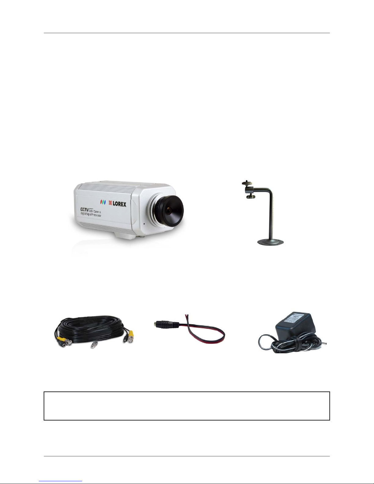
Package Contents
1 x Color Camera with Fixed
Wide Angle Lens
1 x 60ft Extension Cable
1 x BNC-to-RCA Adaptor
WARNING - REGULATED 12V DC 500mA power supply is provided for use with this camera. Use of
a non-regulated, non-conforming power supply can damage this product and will void the warranty.
1 x Power Adaptor Cable
(attached)
1 x Mounting Stand
1 x 12V DC Power Adaptor
ii
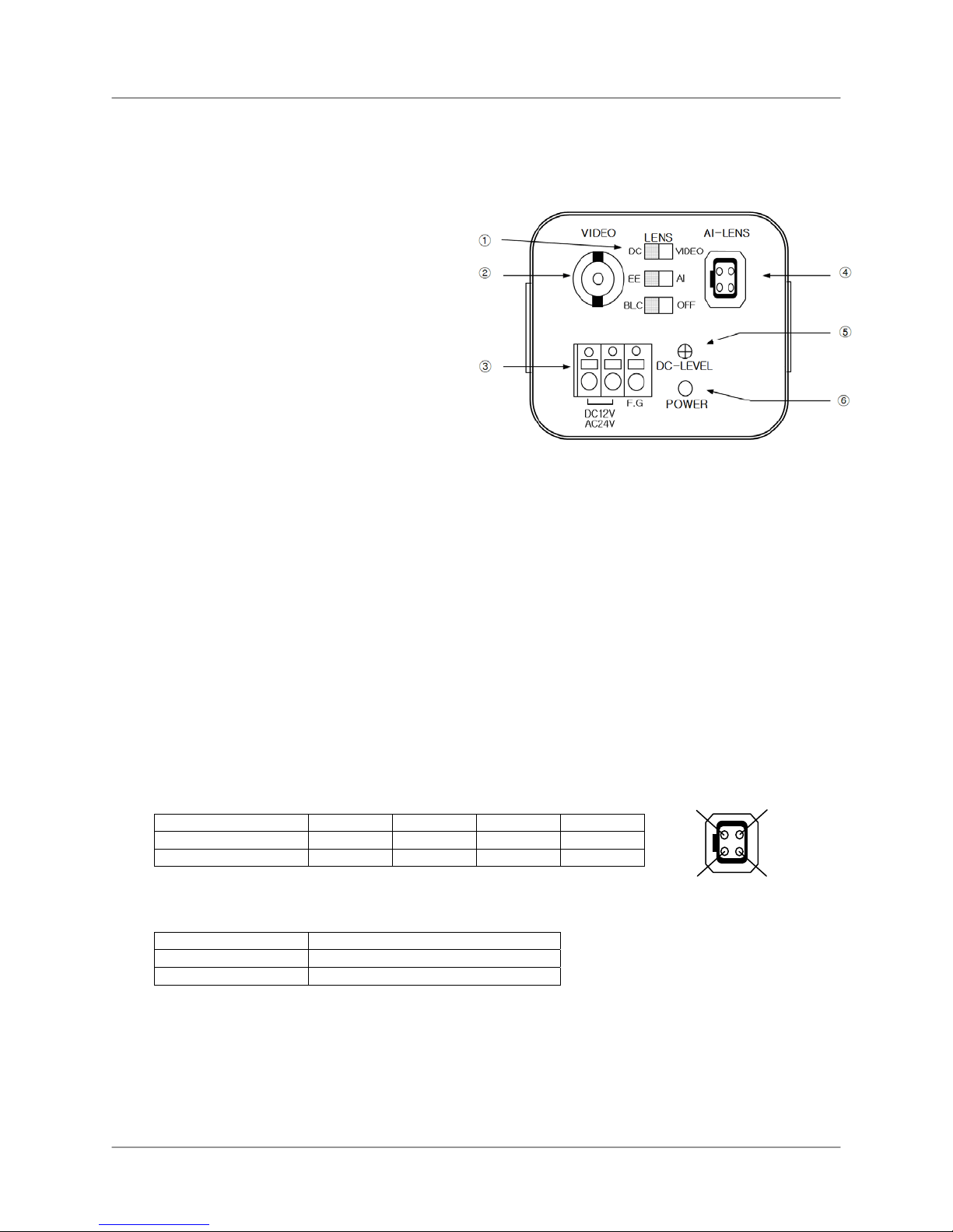
Camera Switches
Camera Switches
Please set the Camera Switches prior to powering on the Camera.
① Function Selection Switches:
AUTO IRIS LENS Switch – Set the
switch to either the “DC” or “VIDEO”
position, depending on the type of
lens attached to the camera. Set the
switch to “DC” for the supplied lens, or
any non AI lens types.
EE/AI Switch – When using an Auto
Iris Lens on the camera, set the
switch to the “AI” position. Set the
switch to “EE” for other lens types,
including the supplied lens.
BLC/OFF Switch – If the camera is
directed towards a backlight, objects
in the image may appear dark. Set the switch to the “BLC” position to turn on the
Backlight Compensation, and improve the image quality in backlight conditions.
NOTE: This camera is NOT supplied with an Auto Iris lens. The default Switch Settings are:
DC, EE & BLC
② Video Out (BNC): Connect the camera to a BNC Cable, or to the provided BNC Extension
cable to transmit video to a receiver, such as a DVR, Observation System, TV or other
similar viewing device. The included BNC to RCA Adaptor may be needed for proper
connection to your viewing device.
③ Power Connector Block: This camera can be powered using either 12V DC or 24V AC
power, and has a removable 12V DC Power Cable. To use 24V AC Power, remove the 12V
DC Cable, and connect directly to a 24V AC Power source.
④ AUTO IRIS LENS Connector: Used to connect the cable from the Auto Iris lens to the
Camera.
1 2 3 4
DC TYPE
VIDEO TYPE
DAMPING- DAMPING+ DRIVE+ DRIVEDC 9V N.C IRIS SIGNAL GND
1
2
⑤ DC LEVEL Brightness Adjustment: The DC Level adjustment controls the brightness of the
connected Auto Iris Lens.
Monitor picture Adjustment direction
Brighten the Image Turn clockwise
Darken the Image Turn counterclockwise
To use this control, the camera must have a connected Auto Iris lens, and the switches must
be set to the “AI” & “DC” positions.
⑥ Power ON/OFF LED: The LED displays the ON or OFF status of the camera. The LED will
illuminate in green when the camera is ON.
3
4
iii

Installing the Camera
Installing the Camera
1. Mount the camera stand to the desired mounting
surface.
2. Attach the Camera to the supplied stand at the
connection point located on the bottom of the camera.
Use the Thumbscrew on the stand to adjust the position
and aim of the camera, and tighten the screw to secure
the position.
3. Connect the Extension cable to the Camera:
• Connect the BNC end of the cable to the
4. Connect the BNC end of the Extension Cable to the
DVR / Observation System or to a TV/VCR.
NOTE: Connect the BNC to RCA Adaptor as needed to
allow for proper connectivity.
5. Connect the A/C Power Adaptor to the Extension
Cable (Black connector). Plug the Power adaptor to a
wall outlet
Camera
• Connect the Power Adaptor connector to the AC
Power Cable attached to the camera.
Remember to check the ends of the cable before
permanent installation, as the power connection
ends are different (one side has a female barrel
power connection, and one end has a male power
plug)
VIDEO INPUT:
Connect the BNC
cable to the video
input of the monitor,
and connect the
power adaptor to an
outlet.
Camera Setup Diagram
CAMERA:
Connect the BNC
and Power cables
to the Camera
iv

Lens Installation
The lens on the Camera can be changed to one of the
following types:
Installing C-MOUNT LENS
1. Removing the Protection Cap
2. Screw the new lens onto the camera by turning
clockwise.
Installing CS-MOUNT LENS
1. Remove the Protection Cap and C-Mount Adapter.
2. Screw the lens onto the camera by turning
clockwise.
Lens Installation
Protection Cap
C-mount adapter
CS-Mount Lens
Installing AUTO IRIS LENS
1. Removing the Protection Cap.
2. Screw the lens onto the camera by turning
clockwise.
3. Connect the Auto Iris Lens Power Cable to the Auto
Iris Lens Connector on the rear of the camera.
4. Set the DC/VIDEO Selection Switch to either “DC”
or “VIDEO” (depending on the type of lens). Set the
EE/AI Selection Switch to AI when using an Auto Iris
Lens.
Auto Iris Lens Power Connector
Lens Switches
v

Camera Specifications
Camera Specifications
Model No. CVC8001
Type PROFESSIONAL COLOR CCD CAMERA
Image Sensor 1/3 “COLOR CCD
Effective Pixel 512(H)×492(V)
Resolution 420 TV Line
TV Type NTSC
Sync. Type Internal
Scanning System 2:1 Interlace
Video Output
1.0V
Gamma 0.45
Min. Illumination 0.05 Lux (F/1.2)
S/N Ratio 48dB or more (AGC off)
Gain Control Automatic
Shutter Speed 1/60~1/100,000sec(NTSC)
Power (DC12V,130mA / AC24V)±10% Dual Power, Non Polarity
Reverse Polarity
Protection
Yes
, Termination 75Ω
P-P
Lens Included 3.6mm Lens / C Mount
Operation Temp. -10°C ~ +50°C
Preservation Temp. -30°C ~ +80°C
Dimension 25.2”/ 64mm X 47.2”/120mm X 21.7”/55mm (W X D X H)
Weight Approx. 350g
vi

Notes:
Notes:
vii

Notes:
It’s all on the web
Product Information
User Manuals
Quick Start Guides
Specification Sheets
Software Upgrades
Firmware Upgrades
VISIT
www.lorexcctv.com
Lorex Techno logy Inc.
viii
www.lorexcc tv.com
 Loading...