

Lorex CVC7731 SERIES Quick Start Manual
Contents
• IR Night Vision Camera*
• Mounting Kit*
• 60ft BNC / Power Extension Cable*
• Power Adapter
†
Copyright © 2015 Lorex Technologies Inc.
As our products are subject to continuous improvement, Lorex reserves the right to modify product
design, specifications and prices, without notice and without incurring any obligation. E&OE
CVC7731_SERIES_TRIFOLDQSG_EN_R1
WARNING - A REGULATED UL / CSA APPROVED power supply is
REQUIRED for use with this camera. Use of a non-regulated, non-conforming
power supply can damage this product and voids the warranty.
Warning/Caution
• Read this guide carefully and keep it for future reference
• Follow all instructions for safe use of the product and handle with care
• Do not disassemble the camera
• Do not point the camera directly towards the sun or a source of intense
light
• Use only the supplied regulated power supply. Use of a non-regulated,
non-conforming power supply can damage this product and voids the
warranty
• Periodic cleaning may be required. Use a damp cloth only. Do not use
harsh cleaners or aerosol cleaners
• The supplied extension cable is rated for surface mounting only
• Cables for in-wall / floor-to-floor installations are sold separately
Installation Tips
• Point the camera where there is the least amount of obstructions (i.e. tree
branches)
• Install the camera in a location that is difficult for vandals to reach
• Secure cabling so that it is not exposed or easily cut
• Camera rated for outdoor use. Installation in a sheltered location
recommended
WEATHERPROOF
NIGHT VISION SECURITY CAMERA
Quick Start Guide
English Version 1.0
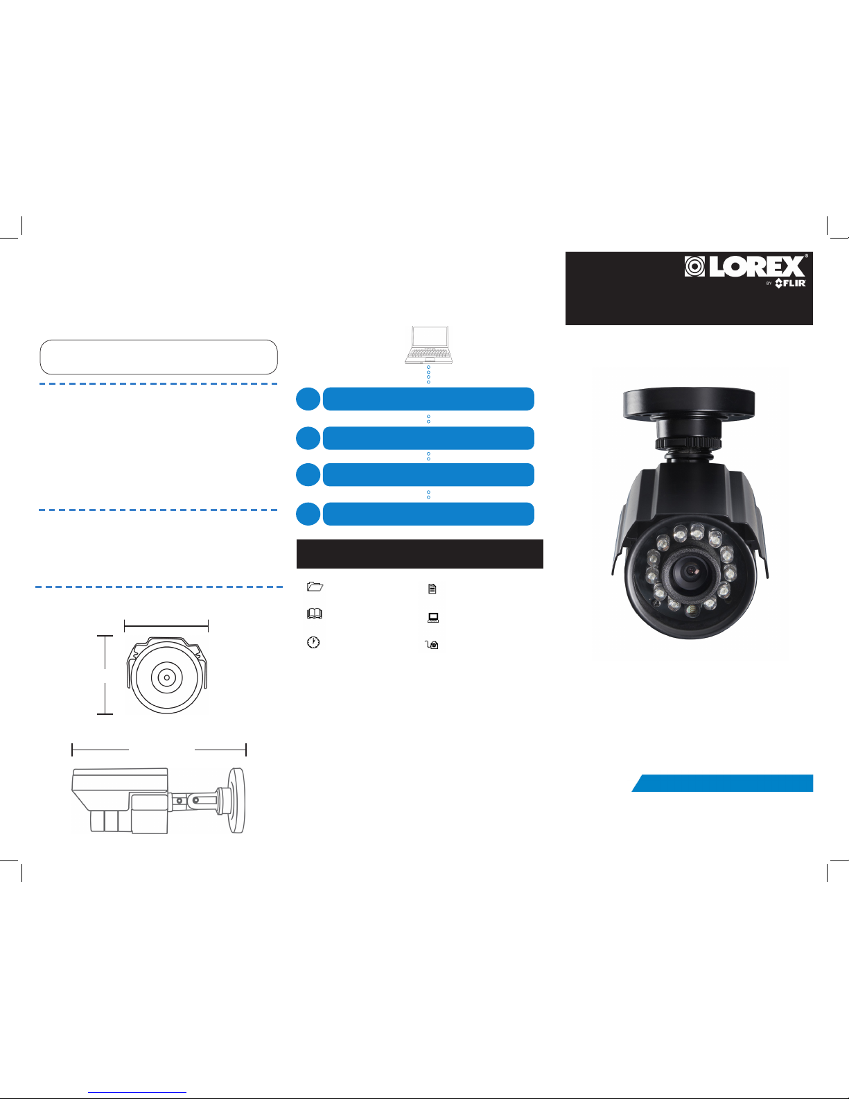
160mm / 6.3”
52mm / 2.0”
Dimensions
*Model CVC7731PK4 is a 4-pack that includes four of the listed items.
†
A “4-in-1” Power splitter cable may be provided depending on product configuration.
55mm / 2.2”
CVC7731 SERIES
Go to www.lorextechnology.com
Search the model number of your product
Click on your product in the search results
Click on the Downloads tab
1
2
3
4
Need Help?
Visit us online for up-to-date
software and complete instruction manuals
Resources
THE FOLLOWING RESOURCES ARE ALWAYS AT
YOUR FINGERTIPS
Product Information
User Manuals
Quick Start Guides
Specification Sheets
Software Upgrades
Firmware Upgrades
Setup Diagram
Power Adapter
Individual Power Adapter
4-in-1 Power Splitter Cable
Connect a BNC-to-RCA Adapter (not included, Lorex model #
BNCB) to connect the extension cable to RCA inputs (i.e. for a TV
connection).
Before installing the camera:
• Decide whether to run the cables through the wall /
ceiling (drilling required) or along the wall / ceiling.
• If you run the cables along the wall / ceiling, you
must run the cable through the cable notch on the
base. This will keep the camera base flush to the wall
/ ceiling when mounted.
To install the camera:
1. Set the camera in the desired mounting
position and mark holes for the screws.
2. Drill the holes, then feed the cable through the
mounting surface or cable notch and mount
the camera stand to the surface using the
provided screws. Make sure all three screws
are fastened tightly at the connection points.
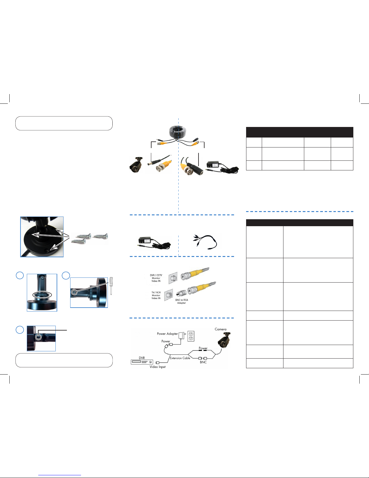
Installing the Camera Cable Extension Options
Extend the cable run for your camera up to 300ft or more
depending on the cable type used. See table below:
Option Cable Type Max Cable
Run Distance
Max # of
Extensions
1 Regular BNC
(supplied with camera)
180ft / 55m 3
2 ‘RG59’ or ‘Coax’ or
‘Coaxial BNC’
(sold separately)
300ft / 92m 5
3 Lorex Universal Cable
(sold separately)
300ft / 92m 3
Notes:
1. For optimal performance, consider using option 2 or 3. It is best to use
the same cable type for the entire distance.
2. Cable run recommendation based on typical camera power consumption
(up to 500mA). For specialty cameras with higher current consumption,
maximum cable run may be reduced. Consider providing power to the
camera at the camera side, rather than at the end of the extension cable.
3. Indicators that your cable run may be too long:
• Video is permanently black & white (even during day time)
• Video is distorted
ATTENTION - Test all connections and ensure the camera is working
correctly prior to permanent installation by temporarily connecting the
camera(s) and cable(s) to the viewing / recording solution.
Problem Solution
No picture / signal • Ensure your TV is on the correct input channel.
Common terms of an input channel: INPUT, AV
CHANNEL, LINE1, LINE2, AUX
• If your camera is connected to a VCR / DVR,
ensure it is properly connected to your TV /
Monitor
• Ensure connections are properly connected
• Ensure the camera power supply is plugged in
Picture is too bright • Ensure your camera isn’t pointed directly at a
source of light (e.g. sun or spot light)
• Slide the sunshade (bullet cameras featuring
adjustable sunshades only) forward to block
excess light
• Move your camera to a different location
Picture is too dark • If using during the day, the camera may not be
getting enough light. Slide the sunshade (bullet
cameras featuring adjustable sunshades only)
backwards to let in more light
• Check the brightness and contrast settings
of the device your camera connects to (TV /
Monitor / DVR)
Night vision is not
working
• The night vision activates when light levels
drop. The area may have too much light
Picture is not clear • Check the camera lens for dirt, dust,
spiderwebs. Clean the lens with a soft, clean
cloth
• Make sure that the cable run is within the
limitations specified in the section ‘Cable
Extension Options’
Bright spot in video
when viewing camera
at night
• Night vision reflects when pointing a camera
at a window. Move the camera to a different
location
BNC connection does
not connect to my TV
• Use a BNC to RCA adapter at the end of the
extension cable
Troubleshooting
To Camera:
To DVR:
Male Power
BNC
1. Connect the BNC and
power connectors to the
camera.
Female Power
2. Connect the BNC connector to
the video input of the DVR.
3. Connect the power connector
to the power adapter. OR
Connect each camera to the
power adapter via a 4-in-1power
splitter.
Connecting the Camera
3. Set the position and angle of the camera using
a Phillips-head screwdriver (not included).
1) Turn the ring to tighten / loosen
the stand connection. Adjust the
camera’s horizontal position.
2) Loosen the lower screw to
adjust the camera’s vertical
position.
3) Loosen the upper screw to
rotate the camera’s position
relative to the stand.
1
2
Connecting the Camera to a TV
A 4-in-1 Power Splitter may be provided depending on product
configuration.
NOTE - This camera features night vision IR LED’s that are completely
invisible to the human eye when activated. The IR LED’s will not glow red
when night vision is on.
3
 Loading...