

Page 1
IRMS Integrated Remote Management Software
LOREX CLIENT 3.0
SOFTWARE MANUAL
Instruction Manual
English Version 2.0
Copyright © 2007 Lorex Technology Inc.
www.lorexcctv.com
Page 2

Lorex Client 3.0 – Integrated Remote Management Software
Table of Contents
Overview........................................................................................- 2 -
Installation .....................................................................................- 4 -
Remote Site Setup ..........................................................................- 7 -
Favorite Group..............................................................................- 12 -
Live View...................................................................................... - 15 -
Playback.......................................................................................- 17 -
Local Setup................................................................................... - 21 -
Remote Setup...............................................................................- 26 -
Appendix A – Remote access via web browser.................................- 36 -
Appendix B – Lorex Player 3........................................................... - 39 -
Appendix C - Lorex Backup Player 3 – Main Window ........................ - 43 -
Installing the Lorex Backup Player 3............................................ - 43 -
Lorex Backup Player 3 – Main Screen .......................................... - 47 -
Appendix D – Network Setup..........................................................- 51 -
Appendix E – Storage Calculator.....................................................- 58 -
Overview
This manual describes the operating procedures for the Lorex Client 3.0 IRMS (Integrated
Remote Management System) software designed for the L19LD800 Series Observation
System.
Lorex Client 3 - Features
The Lorex Client (IRMS program) is the integrated software that controls system
management, video monitoring and image playback of multiple remote systems. The
IRMS offers the following features:
• Check and report on the system status at a remote site
• Notification of the event detection from remote sites
• Remote monitoring of live camera images
• Time-lapse and calendar search of recorded images
• Remote software upgrades and system programming
• Remote Archive from the Combo DVR
- 2 -
Page 3
Lorex Client 3.0 – Integrated Remote Management Software
Lorex Player 3 - Features
The Lorex Player is used to view video clips that are saved to:
• Archived to a USB Thumbstick (not included)
• Archived to a Removable CD-ROM Burner (not included)
Lorex Backup Player 3 – Features
The Lorex Backup Player 3 Application is a stand alone program that can be installed to
playback:
• Data archived to a removable Hard Drive (not included).
• Data mirrored to a removable Hard Drive (not included).
Product Components
• LCD & DVR Combo Unit (with pre-installed Hard Drive)
• Power Adaptor
• 10’ Ethernet Cable
• Remote Control
• Hardware Manual
• Software Manual (This Document)
• Software Installation CD
System Requirements
Operating System Microsoft Windows 98, Microsoft Windows ME, Microsoft
Windows 2000, Microsoft Windows XP or Microsoft
Windows Vista.
CPU Pentium IV 2.4Ghz, 512MB RAM, 10GB free disk or
greater
RAM 64MB or greater
Video AGP, Video RAM 32MB or higher (1024x768, 24bpp or
greater)
- 3 -
Page 4
Lorex Client 3.0 – Integrated Remote Management Software
Lorex Client Installation
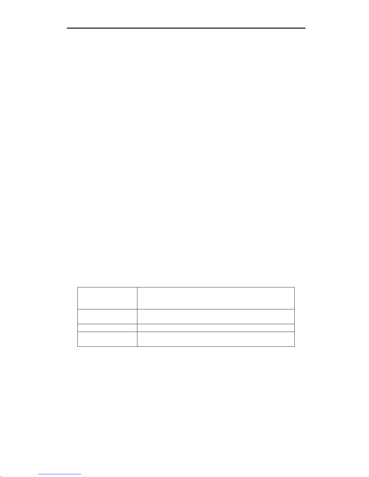
1. Insert the installation CD into your computer. The following installation guide window
appears.
Note: Product Documentation, Networking guides, and a video tutorial for camera
installation are available on the CD. Please take this opportunity to register your product.
This provides you with product warranty protection and product updates.
2. Click on the Lorex Client button to start the software installation for the Lorex Client
and Lorex Player.
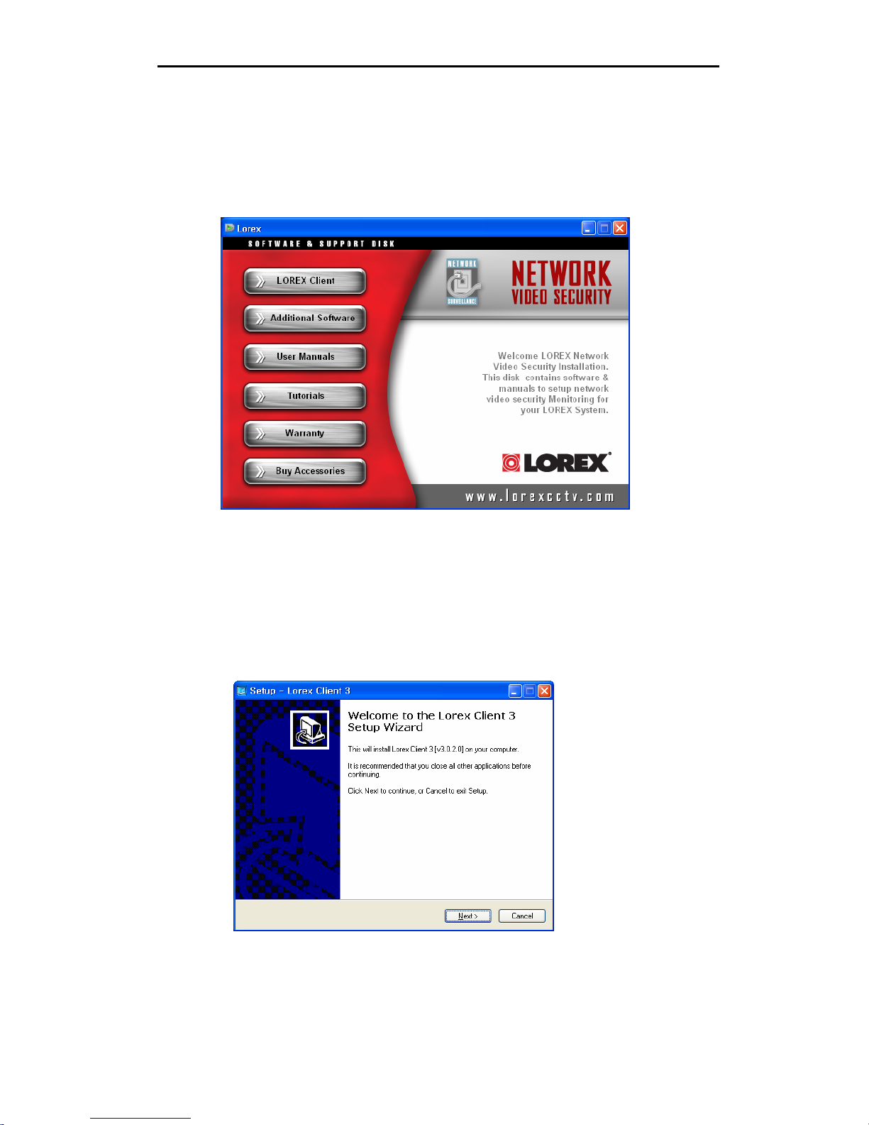
3. When the following dialog box appears, click the Next button.
- 4 -
Page 5
Lorex Client 3.0 – Integrated Remote Management Software
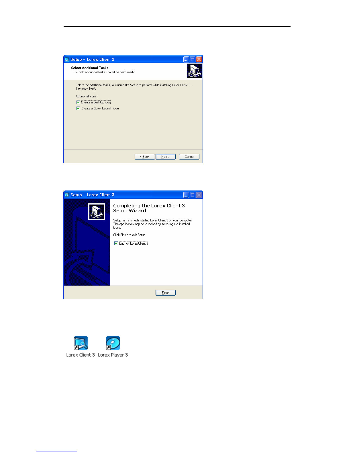
4. Click Next
5. Click Finish to complete the installation
The Lorex Client and Lorex Player icons are created on the Desktop.
- 5 -
Page 6
Lorex Client 3.0 – Integrated Remote Management Software
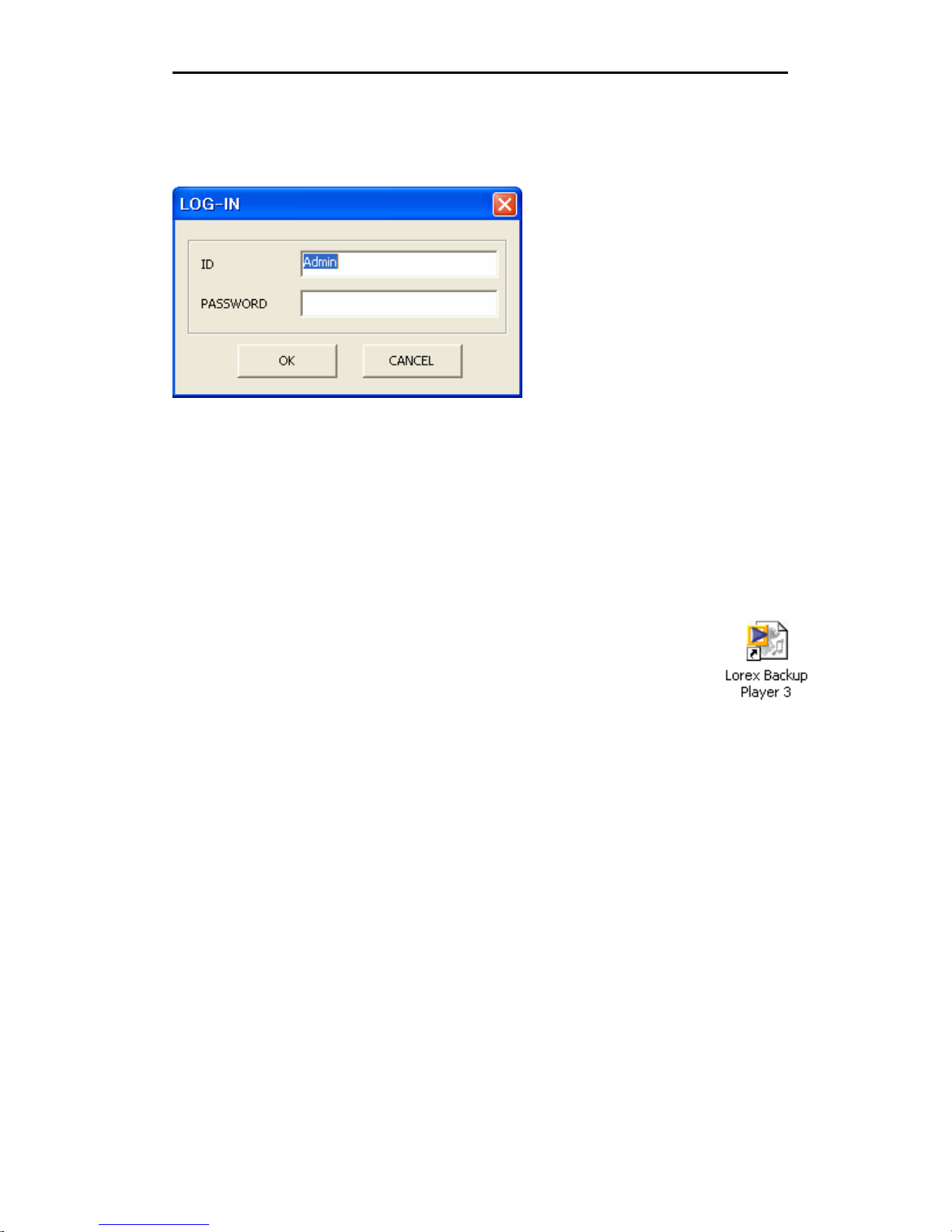
After installing the Lorex Client software, run the program by double clicking on the Lorex
Client desktop icon. The log-in window may appear before the main IRMS program
window loads.
Enter your password to start the Client software.
Note: The Initial password is blank. Refer to the Local Set Up section for instructions
about changing the password settings.
The Lorex Backup Player 3 Application is a stand alone program that can be
installed on another PC to play back data archived or mirrored to a
removable Hard Drive. This application must be installed separately – please
refer to “Appendix B – Lorex Backup Player 3” for details.
- 6 -
Page 7
Lorex Client 3.0 – Integrated Remote Management Software
Remote Site Setup
The following steps outline the setup for the Client software (for Remote Connection).
Menu
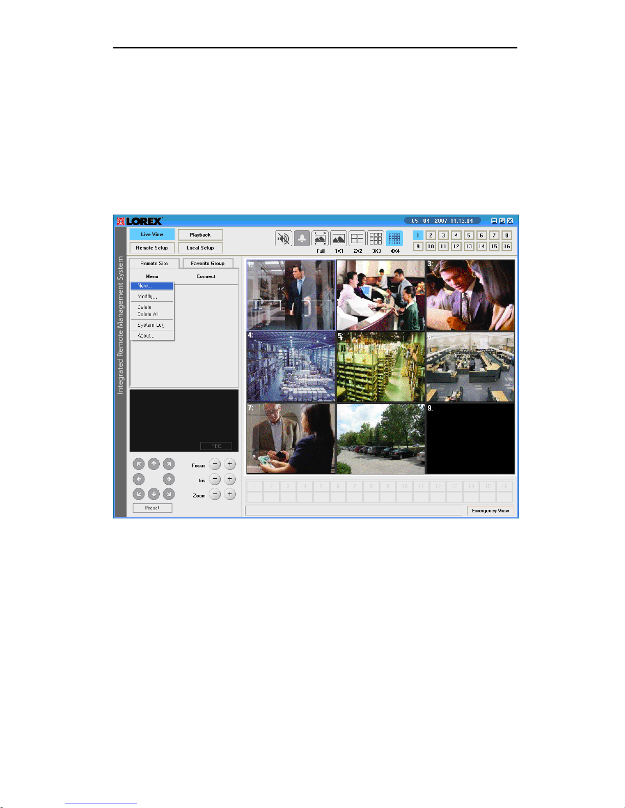
Click the Remote Site button, and then click the “Menu” button to add a new remote site.
The following drop down menu will appear:
Menu fields include:
• New: Adds and registers a new remote site.
• Modify: Displays the information about all remote sites registered. You can see
the pop-up window.
• System Log: Displays the system log data of the remote site selected.
• Delete: Deletes the currently selected remote site.
• Delete All: Deletes all sites registered before.
• About: Displays Lorex Client software version
- 7 -
Page 8
Lorex Client 3.0 – Integrated Remote Management Software
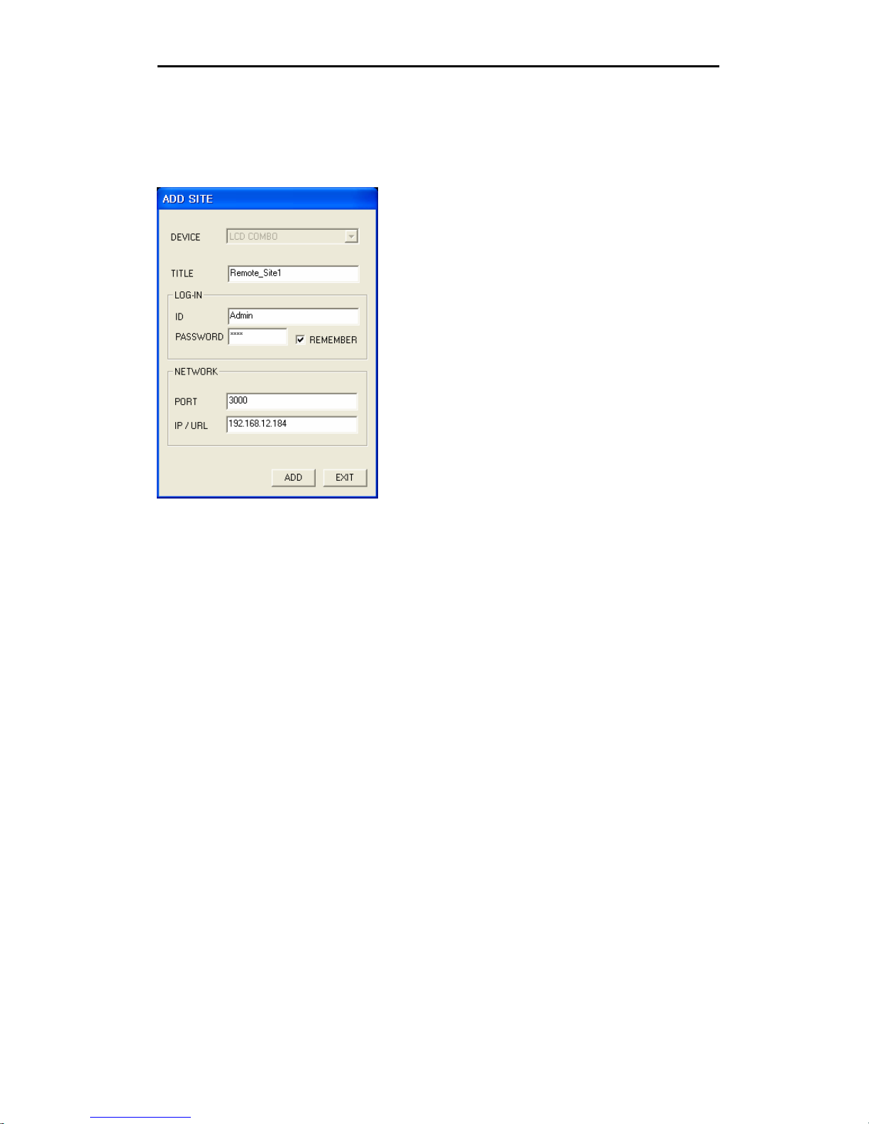
Select the “New” option in the drop down menu, and enter the information for the
remote site to register.
The Add Site dialog box appears (see below).
Options include:
• DEVICE: Set by default to “LCD COMBO”.
• TITLE: Enter a name for the remote site.
• ID: Enter the log-in ID of the remote system (default: Admin)
• PASSWORD: Enter the log-in password of the remote system (default: blank/no
password)
• REMEMBER: If this option is checked, you can connect to the remote site without
entering password each time.
• PORT: Displays an initial port number. The port must match the one assigned to
the remote system to connect). The default port is set to 3000.
• IP/URL: Enter the IP address or domain name of the remote system:
o The Local IP address (e.g. Local Network Connection IP 192.168.12.184)
o Remote IP address (e.g. Wide Area Network IP address 72.68.122.45)
o DDNS address (e.g. myurl.strategicvista.net) for the remote site. If
registered with the LOREX DDNS service, you can enter only the prefix of
the URL. (without the suffix: .strategicvista.net).
Note: Please refer to “Appendix C - Network Configuration and Setup” for configuration
details.
- 8 -
Page 9
Lorex Client 3.0 – Integrated Remote Management Software
Connection
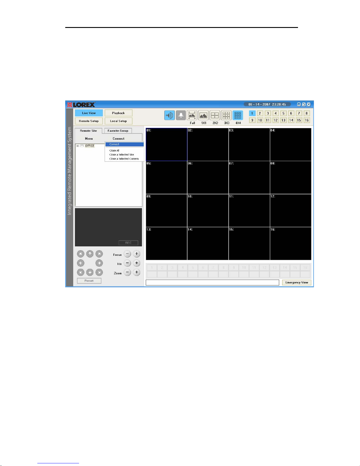
▶ Connect using the “Connect” button.
Select the site you want to connect to from the Remote Site list, and then click the
Connect button.
Select the “Connect” option. The images from the connected system cameras will appear
in the Live View.
- 9 -
Page 10
Lorex Client 3.0 – Integrated Remote Management Software
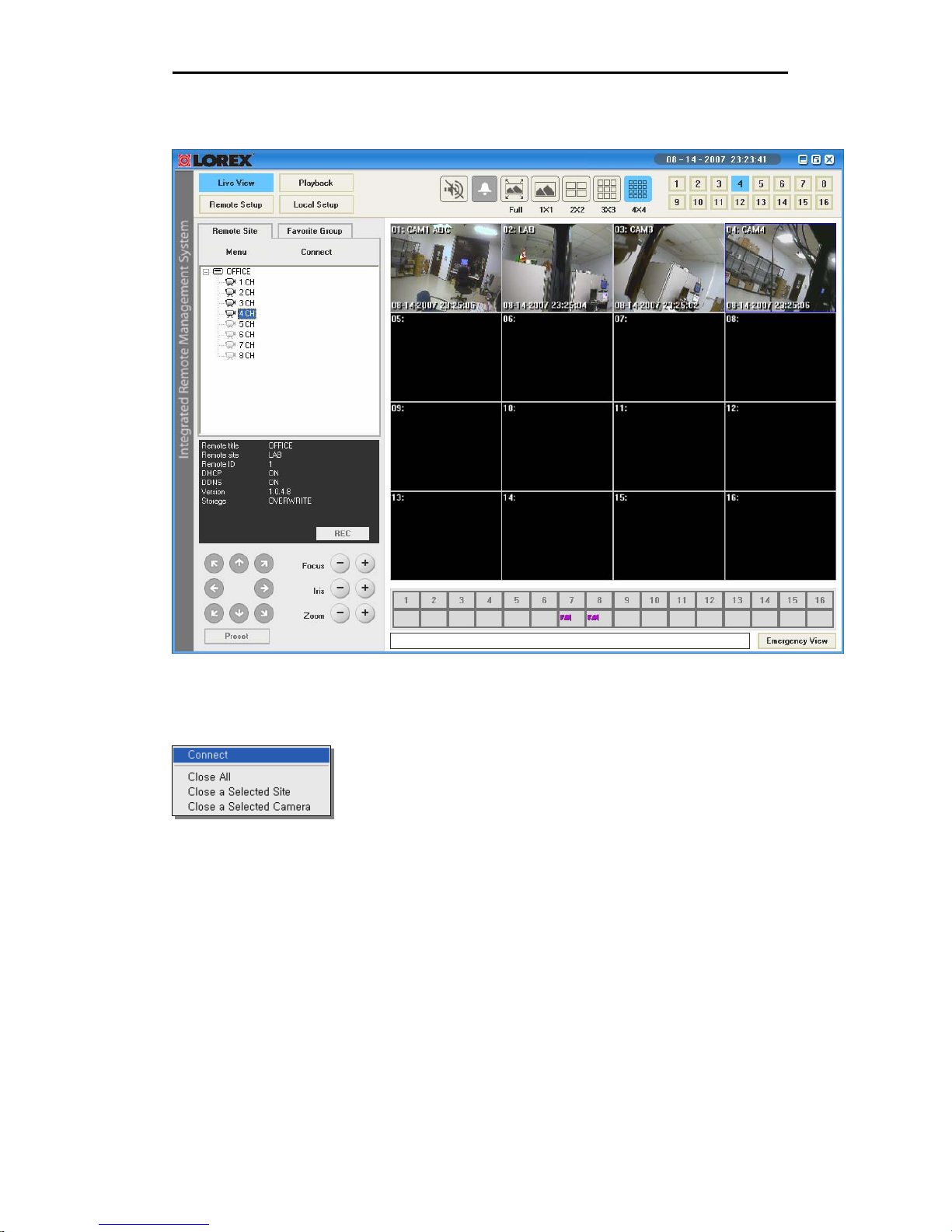
Camera Images when remotely connected to a site:
Connect Menu options include:
• Connect: Connects to the remote site selected.
• Close All: Disconnects from all remote sites currently registered.
• Close a Selected Site: Disconnects the currently selected remote site.
• Close a Selected Camera: Disconnects the currently selected camera channel.
- 10 -
Page 11
Lorex Client 3.0 – Integrated Remote Management Software
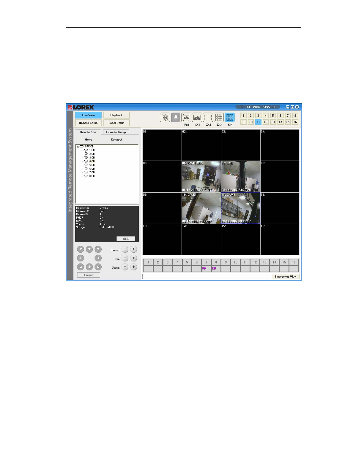
▶ Connection using mouse Drag & Drop
Select a previously configured location from the “Remote Site” window, and drag it to the
live viewing location (camera display) portion of the screen. All cameras from the remote
system will be displayed.
You can also drag specific cameras to any available square in the Live View area, as
shown in the example below
The software has an advanced feature which allows you to connect to multiple sites and
view cameras from different locations simultaneously on one screen (maximum of 16
cameras). Simply drag the specific cameras from each site you wish to connect to into
the live viewing area.
- 11 -
Page 12
Lorex Client 3.0 – Integrated Remote Management Software
Favorite Group
To effectively manage multiple remote sites, it is suggested the sites be assigned to a
Favorite Group.
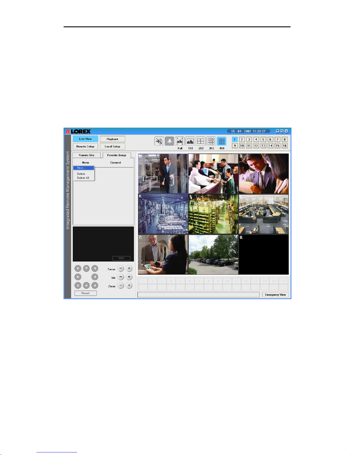
Menu
Click the “Favorite Group” button, and then select the “Menu” button to create a new
favorite group. The drop down menu appears as shown below.
Options include:
• New: Adds and registers a new favorite group.
• Delete: Deletes the currently selected group.
• Delete All: Deletes currently registered all group.
- 12 -
Page 13
Lorex Client 3.0 – Integrated Remote Management Software
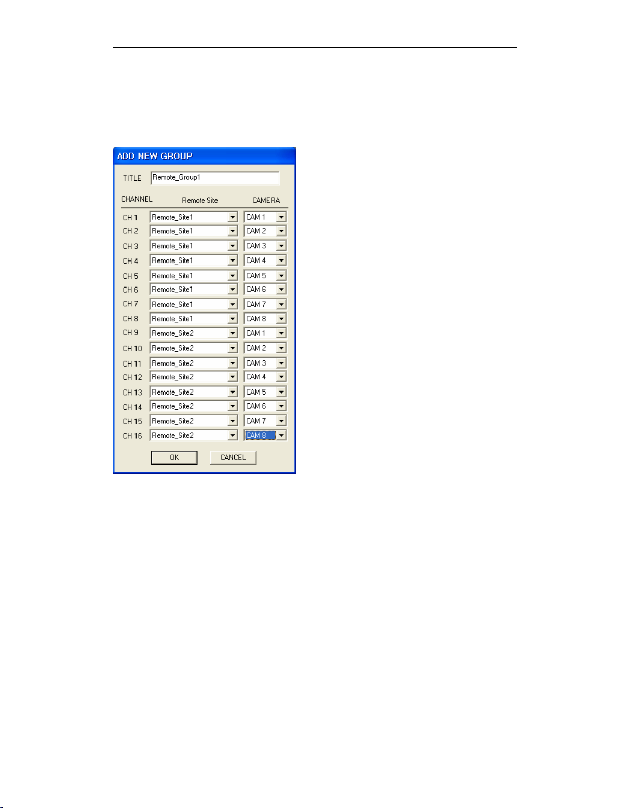
Select the “New” option in the drop down menu, and enter the information for the
favorite group.
The “Add Group” window appears. Enter a group name, and then select previously
configured sites and cameras. Click the OK button to save the settings.
Options include:
• Title: Enter a name for the favorite group.
• Remote Site: Select the remote site to add as a group.
• Camera: Select a camera channel from the selected remote site.
- 13 -
Page 14

Lorex Client 3.0 – Integrated Remote Management Software
▶ Connect to the Remote Sites using the “Connect” button
Select the group you want to connect to from the Favorite Group list, and then click the
Connection button to remotely connect to the site.
The drop-down menu is shown below:
Select the ‘Connect’ option. The Lorex Client displays video from the connected cameras
(as configured in the favorite group).
Menu options include:
• Connect: Connects the favorite group selected.
• Close All: Disconnects all remote site currently registered.
• Close a selected group: Disconnects the currently selected favorite group.
• Close a selected camera: Disconnects the currently selected camera channel.
Note: The drag and drop feature also works in the Favorite Group.
- 14 -
Page 15
Lorex Client 3.0 – Integrated Remote Management Software
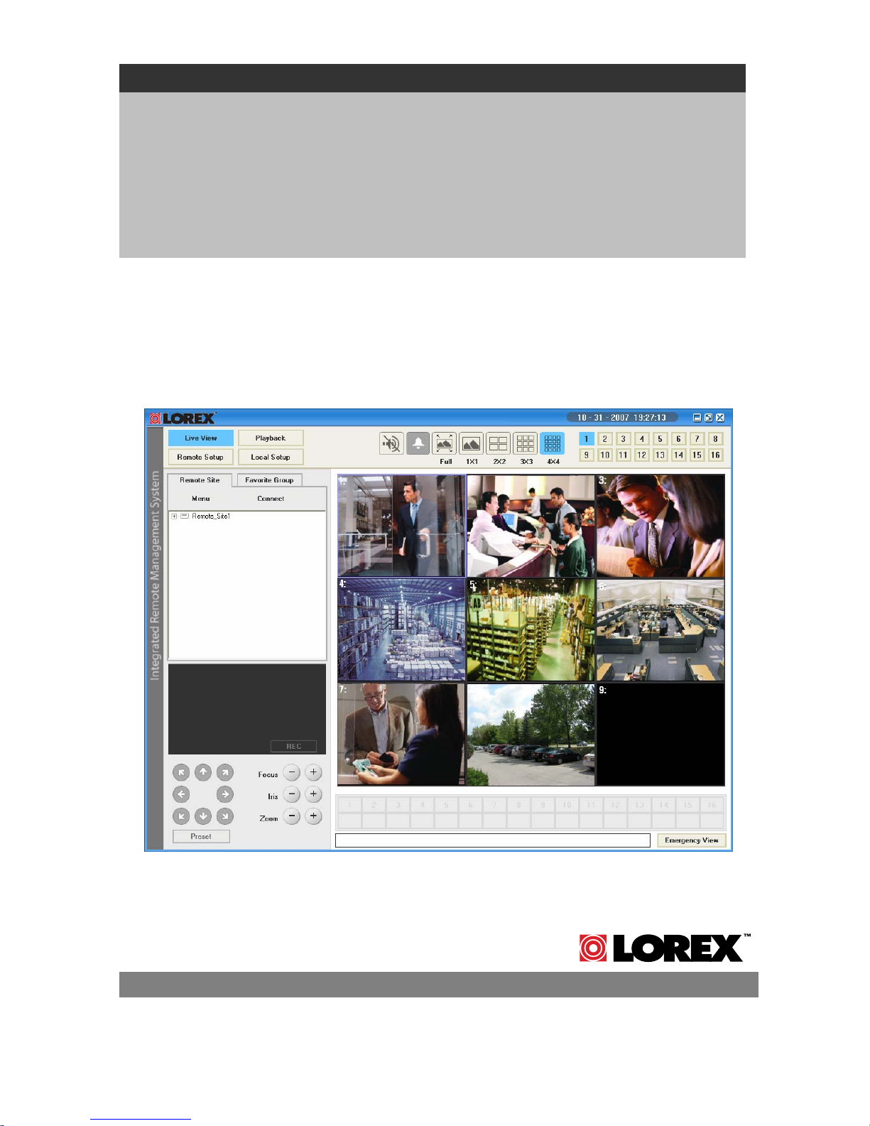
Live View
The Live View provides a remote monitoring function for video images in real time, from
either single or multiple sites. In addition, when an event is detected at a remote site,
the Live View displays the event information, and allows the user to access the remote
site directly to view the associated Video images.
Click on the Live View button
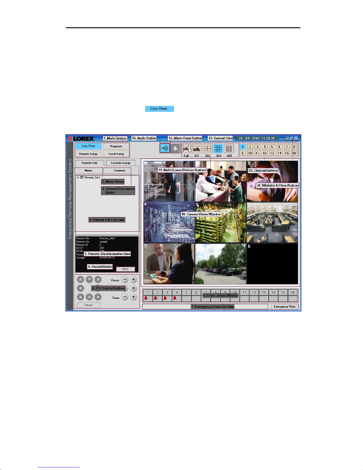
The Graphical User Interface (GUI) of the Live View is shown below:
The fields in the Client Live View window include:
1. Mode Buttons: Includes Live View buttons, Playback buttons, Remote Setup
buttons, Local Setup buttons.
2. Menu Button: New / Modify / Delete / Delete All / System Log / About.
3. Connect Button: Connects or Disconnects the selected remote site
4. Remote Site List: Displays the title of the remote system currently registered.
- 15 -
Page 16
Lorex Client 3.0 – Integrated Remote Management Software
5. Remote Site Information view: Displays the system information of the remote site
selected in the remote site lists
6. PTZ Control: PTZ control buttons.
7. Emergency Event List: Displays an emergency event that was called back from
individual remote site (LAN connection only).
8. Event Viewer: displays real-time event of the remote site.
9. Schedule Recording On/Off button
10. Live Viewer Window: Displays the image for the connected 16 camera of the
remote system currently registered.
11. Multi Screen Division buttons: Includes Full buttons, 1x1 buttons, 2x2 buttons,
3x3 buttons, 4x4 buttons
12. Channel buttons.
13. Current Time.
14. Extension & Close button: Close the Lorex Client program.
15. Alarm Reset Button: Reset the internal beep of the Lorex Client.
16. Audio Button: Enable or disable the audio of channel selected in the Lorex Client
screen.
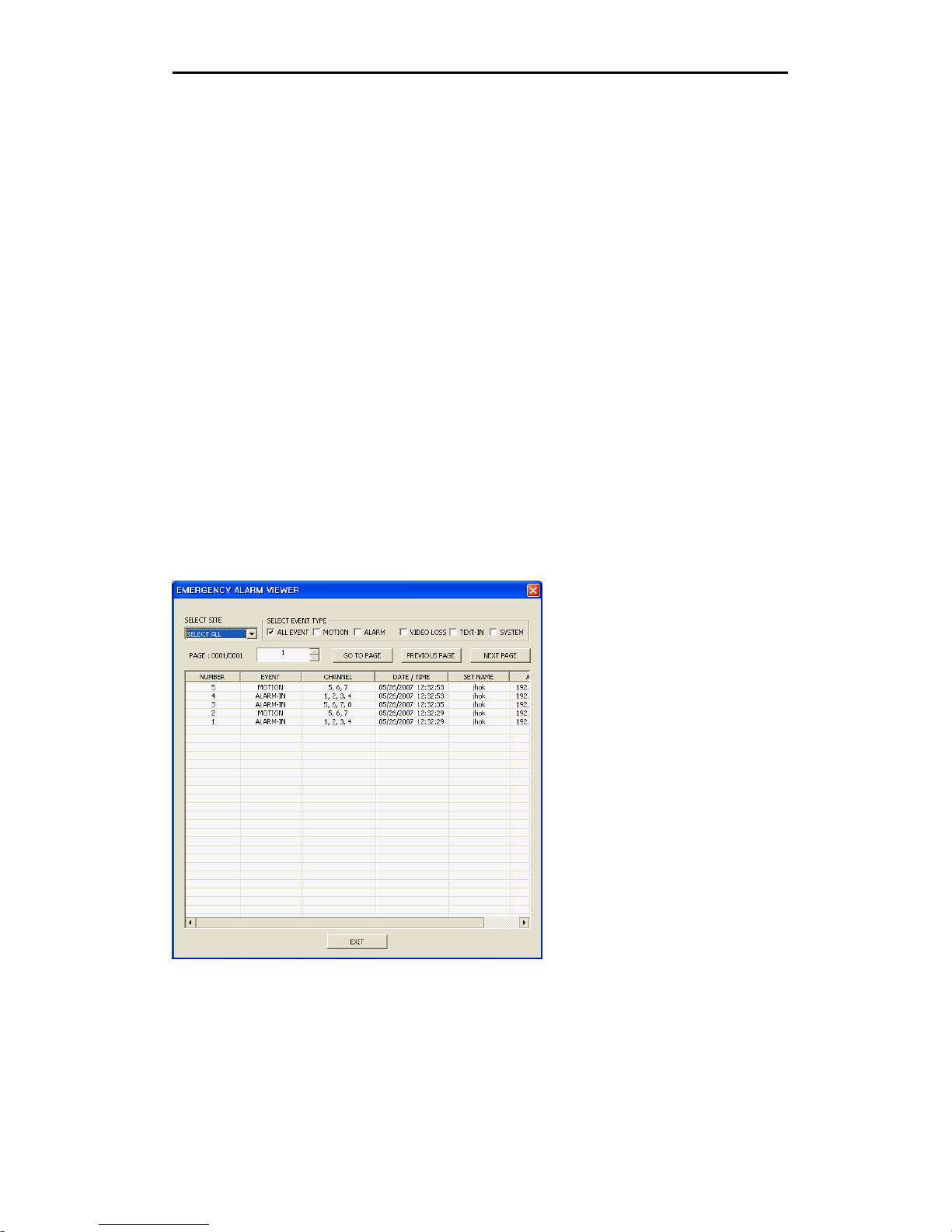
Emergency Event List Display
The Emergency Event List displays the event(s) that were downloaded from individual
remote sites. Press the Emergency View button to see the events list. A window of
Emergency Events is shown below.
- 16 -
Page 17
Lorex Client 3.0 – Integrated Remote Management Software
Playback
The Client Playback searches for recorded images on the remote system, and plays back
the found images. In addition to search and playback functions, the Client Playback also
provides additional functions including file (image) save and file (image) print.
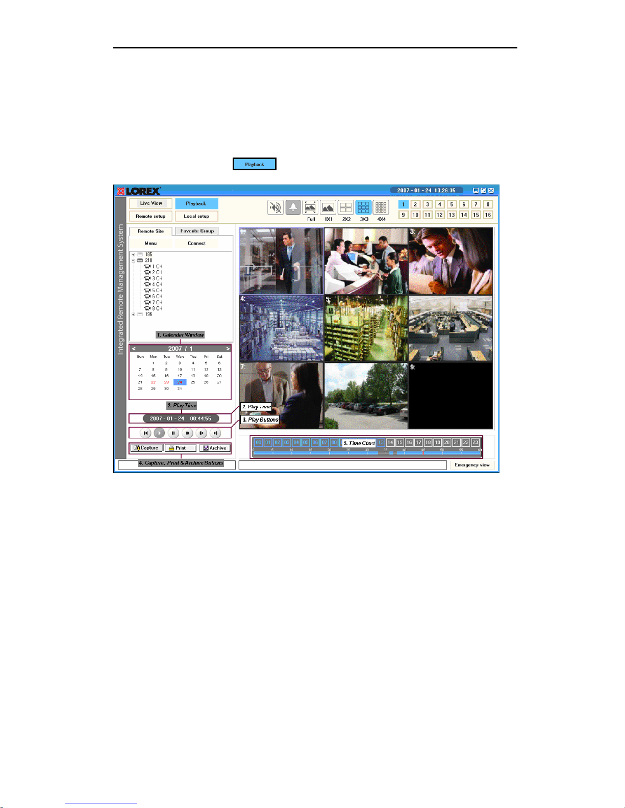
Press the Playback button
Options in the Playback window include:
1. Calendar: Search results from the remote DVR (currently connected) are
displayed by month. If there is a recorded data for a particular date, a blue
square on the date will be displayed.
2. Play Time: Displays the time of the video playing.
3. Play Buttons: You can control the remote DVR by using playback buttons. The
left-most button in the above box is the first item in the list below. Go to the first
/ Pause / Play / Stop / Step forward / Go to the last
4. Capture, Print & Archive: Captures and prints an image on playing. Archives
recorded data from the remote site currently selected to your computer.
5. Time Chart: Displays an hour-based search screen for the chosen date. If there is
data for a channel, a white section will be displayed on a 24-hour basis.
- 17 -
Page 18
Lorex Client 3.0 – Integrated Remote Management Software
Time-Lapse Search
To connect to the Remote Site, use the same steps as connecting in Live View mode.
Once a connection has been established with the remote site, and recorded data has
been located for a particular date, a blue square on the date will be displayed. Selecting a
blue date will display an hour-based search screen for the chosen date. If there is data
for a channel, a white section will be displayed on a 24-hour based time chart.
In Time-lapse mode, the system searches for recorded images by time and plays back
the found images. Selecting a date from the calendar initiates time-lapse search. The
dates for which recording is available are displayed in blue characters.
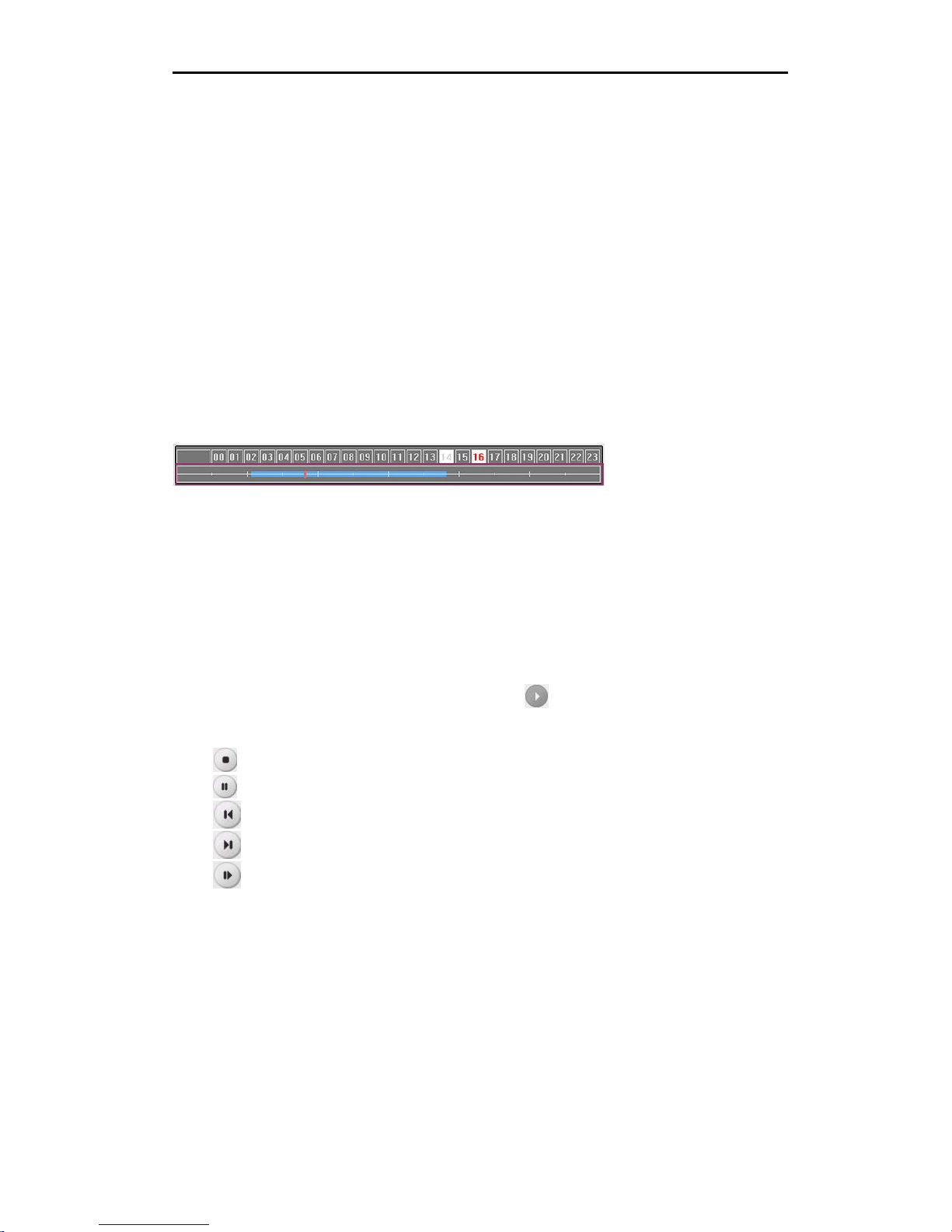
Select a specific hour by clicking on the desired hour segment. A minute-based search
window will be displayed (shown below). If there is data for a channel, a blue section will
be displayed in a 60-minute segment.
Select the specific minute by clicking on the desired minute segment. Video images will
be played back starting with the first image captured within the one-hour segment.
Playback
Select a specific minute by clicking the mouse on the desired minute segment. Video
images will be played back starting with the first image captured within the one-hour
segment.
Video Playback can also be started by pressing the
The playback buttons include:
Press
Press
Press
Press
Press
A blue bar in 60-minute search window indicates the playing time of recorded data.
Note: The speed of fast forward playback is dependent on the network bandwidth and
the number of images per second (FPS).
button to stop playback.
button to pause playback.
button to go to the first.
button to go to the last.
button step forward.
button.
- 18 -
Page 19

Lorex Client 3.0 – Integrated Remote Management Software
Additional Functions
▶ Capture ( *.BMP )
Click the Capture button to save the current image in a bitmap file format to the local
hard disk drive or floppy disk. The Save Image window is shown below. Select the save
location, and press the ‘Save’ button.
▶ Print
Click the Print button to print the current image on the printer connected to your
computer. The Print window is shown below. Select a printer, and press the ‘Print’ button.
- 19 -
Page 20

Lorex Client 3.0 – Integrated Remote Management Software
▶ Archive
Click the Archive button to archive the recorded video from the remote site (currently
connected to your computer). The archive window is shown below.
Select the Days and Time Range, the channel you want to archive and press the
ESTIMATE button to calculate the size of the data to be archived.
The size is displayed in the FILE SIZE field. Enter the
name and location of the file to be archived and press
the START button. The progress bar will be displayed.
Note: During Archiving, you cannot do any other job
with the Client software until archiving is completed.
- 20 -
Page 21

Lorex Client 3.0 – Integrated Remote Management Software
Local Setup
The Lorex Client ‘Local Setup’ controls the behavior of the Local install of the IRMS
program. Press the Local Setup button
the IRMS Local Setup is shown below.
. The Graphical User Interface (GUI) of
System
You can set up a system password and Buzzer option. Select the “System” menu in the
Local Setup window to set up the local system.
The admin can register and modify the Client user. The number of User is maximum 20
including the Admin.
USER:
• ADD: Add new User.
• DELETE: Delete User
• MODIFY: Modify User information.
- 21 -
Page 22

Lorex Client 3.0 – Integrated Remote Management Software
PASSWORD CHECK:
• APPLICATION START: Checks the password when starting the Client software.
• APPLICATION FINISH: Checks the password when exiting the Client software.
• ENTER SETUP: Checks the password when entering local or remote setup.
• BUZZER: Sets the internal buzzer of local system to ON or OFF. Set an
appropriate hold time from the point of detection of event.
• EMERGENCY ALARM: Check the ON box to receive emergency event notification
from remote sites.
Remote Update
The firmware can be upgraded through the IRMS software to the remote System.
Select the “Remote S/W Upgrade” menu in the Local Setup window.
You can simultaneously select multiple remote sites and check selected systems. The
installation results are displayed in the “Results” box.
- 22 -
Page 23

Lorex Client 3.0 – Integrated Remote Management Software
Select the remote site to upgrade from the “Remote Site” field, and load an upgrade file
by clicking the S/W data Load button. Click the “Start” button to begin the remote
firmware Upgrade for the target remote site(s).
Menu options include:
• REMOTE SITE: The remote site(s) currently registered.
• LOAD F/W DATA: Load the upgrade file from the local system.
• START: Upgrades the system(s) on the remote site(s) selec ted in the Remote site
list.
• STOP: Stop the current S/W Upgrade.
• RESULT: Displays results of the current setup.
Local Log View
Displays the System log information for the Lorex Client. Select the “Local Log View”
menu in the Local Setup window. If the user sets the period of interest and clicks the
FIND button, the system log entries within the period are displayed in the list.
- 23 -
Page 24

Lorex Client 3.0 – Integrated Remote Management Software
Menu options include:
• FROM: If this box is checked, search from the first emergency event log. If you
want to a specific starting date/time, remove a check and then set the desired
date/time.
• TO: If this box is checked, search until the last emergency event log. If you want
to a specific ending date/time, remove a check and then set the desired
date/time.
• FIND: Displays emergency event log entries within preset period.
• SAVE AS: Saves the log information to the Excel file format.
• DELETE: Deletes a log selected.
• CLEAR: Deletes all data on system log in your PC.
Emergency Log View
Displays the log of emergency events downloaded from remote sites. Select the
“Emergency Log View” menu in the Local Setup window. Select dates, and click the FIND
button. The emergency event log entries within the period are displayed in the list.
- 24 -
Page 25

Lorex Client 3.0 – Integrated Remote Management Software
Options include:
• FROM: If this box is checked, search from the first emergency event log. If you
want to a specific starting date/time, remove a check and then set the desired
date/time.
• TO: If this box is checked, search until the last emergency event log. If you want
to a specific ending date/time, remove a check and then set the desired
date/time.
• FIND: Displays emergency event log entries within preset period.
• SAVE AS: Saves the log information to the Excel file format.
• CLEAR: Deletes all data on emergency events in your PC.
- 25 -
Page 26

Lorex Client 3.0 – Integrated Remote Management Software
Remote Setup
The Remote Setup allows changes to be made to the configuration of the System from a
remote location. It is possible to control the system and configure menu settings via the
user friendly software interface. This feature not only saves time but also provides
flexibility to make system setting as needed from a remote location.
Select a remote site registered in the remote site window and press the “Remote Setup”
button
NOTE: Please refer to the Hardware Manual for a detailed set of Configuration
Instructions.
- 26 -
Page 27

Lorex Client 3.0 – Integrated Remote Management Software
System
The system menu enables basic configurations for the remote system such as Time/Date,
Display, Language and User. Selecting the System in the Remote Setup Menu displays
System Setup window as above.
Screen Save
Select the Screen Save option in the Remote Setup Menu to configure the function:
- 27 -
Page 28

Lorex Client 3.0 – Integrated Remote Management Software
Event
This menu is used to set event options such as Alarm Input, Motion Detection, Video Loss,
Text-in, System Event, and Action.
Selecting the Event option in the Remote Setup Menu displays Event Setup window:
Alarm-In
Selecting the “Alarm-In” in the Remote Setup Menu displays the options shown above.
- 28 -
Page 29

Lorex Client 3.0 – Integrated Remote Management Software
Motion Detection
Selecting the “Motion” option in the Remote Setup Menu displays the Motion Setup
window.
Set the actions that the system will take whenever it senses a motion detection event,
and camera channels to record when the motion detection occurs.
Select a button in the ZONE field. The Motion Zone setup screen appears and it is
displayed over the video for the selected camera. You can set up motion detection zones
by selecting or unselecting blocks.
- 29 -
Page 30

Lorex Client 3.0 – Integrated Remote Management Software
Motion Zone Screen
CLEAR Blocks - Selected areas
(will detect motion).
PINK Blocks - Unselected areas
(will not detect motion).
Video Loss
Selecting the “Video Loss” option in the Remote Setup Menu displays the Video Loss
Setup window.
You can activate a video loss event by selecting ON in the ON/OFF field. When video loss
occurs on a channel (no input signal from a video input connector), it will be processed
as an event.
- 30 -
Page 31

Lorex Client 3.0 – Integrated Remote Management Software
Text-In
Selecting the “Text-In” option in the Remote Setup Menu displays Text-In Setup window.
You can activate a text-in event by selecting ON in the ON/OFF field.
This menu enables the system to process a text-in input (such as data from a Point Of
Sale device) as an event.
- 31 -
Page 32

Lorex Client 3.0 – Integrated Remote Management Software
System Event
Selecting the “System Event” option in the Remote Setup Menu displays System Event
Setup window.
- 32 -
Page 33

Lorex Client 3.0 – Integrated Remote Management Software
Record
This menu is used to set the recording attributes such as Resolution, Speed, Quality and
Schedule.
As these setup options control the main recording functions of the system, each option
should be fully understood for proper operation.
Please refer to the Hardware Manual for details. Selecting the Record option in the
Remote Setup Menu displays Record Setup window.
- 33 -
Page 34

Lorex Client 3.0 – Integrated Remote Management Software
Camera
Settings related to Camera display and function are available on the Camera Menu.
Select the "Camera" option in the Remote Setup Menu to display the Camera Setup
window.
- 34 -
Page 35

Lorex Client 3.0 – Integrated Remote Management Software
Network
The settings for TCP/IP, RS-232 communication, RS-485 communication, DDNS,
Notification, and Site configurations are in the Network menu.
Selecting the "Network" option in the Remote Setup Menu displays Network Setup
window.
- 35 -
Page 36

Lorex Client 3.0 – Integrated Remote Management Software
Appendix A – Remote access via web browser
To connect to the remote system via IE Web Browser:
1. Launch the Internet Explorer Web Browser on the PC.
2. Enter the remote system address in the Address bar and press ENTER.
Ex. http://192.168.12.188/
http://myurl.strategicvista.net/
Note: If the remote system has no IP address or the IP address is incorrect, users will
fail to connect to the remote system.
3. If a security window for the ActiveX Controller installation appears, Confirm and install
it.
4. If connecting via the web browser for the first time (or there are updated files in the
remote system), the webbrowser may take several minutes to load and display images.
5. Once a connection has been made to the remote system, the Web Browser displays
the following screen:
(Local Network - LAN connection address)
(Internet Connection - WAN DDNS Address)
- 36 -
Page 37

Lorex Client 3.0 – Integrated Remote Management Software
Live Monitoring Screen
Once the Web Browser completes its connection process, it will display the live video
images. The default mode is to display all cameras at once. Pressing any of the camera
buttons will cause that camera to display full screen.
Main Icons
The descriptions of each button used for the operation of the Web Browser are as follows.
1. PTZ Control
Direction Button Iris Button Focus Button Zoom Button Preset Number
2. Camera Number
Pressing any camera button will cause that camera to display full screen.
3. 2x2 Multi Screen
Press this button to change the screen to the 2x2 QUAD screens. Pressing
the button again toggles between QUAD1 (1, 2, 3, 4) and QUAD2 (5, 6, 7,
8).
4. 3x3 Multi Screen
Press this button to change the screen to the 3x3 multi-screen.
- 37 -
Page 38

Lorex Client 3.0 – Integrated Remote Management Software
5. Audio Control
Select a channel number you want to connect in the combo box. Press the audio button
to set the audio level to the minimum level.
6. Setup Menu
Press this button to set the main menu of the remote system selected.
The setup screen is equal to the one of the Client software.
- 38 -
Page 39

Lorex Client 3.0 – Integrated Remote Management Software
Appendix B – Lorex Player 3
If you have installed the Lorex Client software, the Lorex
Player 3 is also installed. The Lorex Player is used to view
video clips that are saved to:
• Archived to a USB Thumbstick (not included)
• Archived to a Removable CD-ROM Burner (not included)
Note: When data is backed up to a USB Thumbstick, the Lorex Player is added as
“Clipveiwer.exe”
To view archived data:
1. Insert a recorded CD, USB stick or USB HDD in your PC.
2. Run the Clipveiwer.exe.
The Lorex Player application is shown below.
The functions are explained on the next page. The Clip Player Screen displays the
clip images.
- 39 -
Page 40

Lorex Client 3.0 – Integrated Remote Management Software
The following buttons are available on the Lorex Player program:
Close button: close the clip player screen.
Image Screen: displaying screen for the video clip data.
Start Time: displays the beginning time of the video clip.
Current Play Time: displays the playing time of the video clip.
End Time: displays the ending time of the video clip.
Time Chart: displays the current position of the video clip in time chart.
Data Find Button: finds and opens the video clip data in the CD you want to play.
Play Control buttons: Go to the first / Step backward / Pause / Play / Stop / Step
forward / Go to the last.
Capture & Print buttons: captures and prints images from the image screen.
Audio Selection: selects an audio channel to be played. Screen Division buttons:
1x1 / 2x2 / 3x3 / 4x4.
- 40 -
Page 41

Lorex Client 3.0 – Integrated Remote Management Software
File Open:
If you run the Player program, the data to be played are displayed on the time
chart. Click the data find button to play other video clip. Then, select the clip
data you want
Playback:
To start playback, click the left button of mouse on the position you want to play
in the time chart. If you click the play button, the playback is started from the
beginning of the video clip.
Play control buttons:
: Play, play the video clip.
: Go to the first, go to the beginning of the video clip.
: Step backward, go back one frame of the video clip.
: Pause, pause playback of the video clip.
: Stop, stop playback of the video clip.
: Step forward, go forward one frame of the video clip.
: Go to the last, go to the end of the video clip.
- 41 -
Page 42

Lorex Client 3.0 – Integrated Remote Management Software
Capture:
Click the capture button to save the current image in a bitmap file format to
the local hard disk drive or floppy disk.
The following window will be displayed. Select the location to be copied.
Print:
Click the print button to print the current image on the printer connected to
your computer. A below window will be displayed. Select and start your printer.
- 42 -
Page 43

Lorex Client 3.0 – Integrated Remote Management Software
Appendix C - Lorex Backup Player 3 – Main Window
The Lorex Backup Player 3 Application is a stand alone
program that can be installed to playback:
• Data archived to a removable Hard Drive (not
included).
• Data mirrored to a removable Hard Drive (not included).
Note: If using the Mirror function, all data on the hard drive will be erased
before the Mirror begins. Make sure that existing data on the drive has
been removed prior to starting the Mirror process.
This application must be installed separately from the “Lorex Client” install
CD, located in the ‘Additional Software’ section.
Installing the Lorex Backup Player 3
1. Launch the Application from the Software CD included with the
System.
2. Select ‘English’ and click the OK button.
- 43 -
Page 44

Lorex Client 3.0 – Integrated Remote Management Software
3. Click the ‘Next’ button
4. Select Additional Icons (if desired) and click ‘Next’.
- 44 -
Page 45

6. Click ‘Install’
Lorex Client 3.0 – Integrated Remote Management Software
7. Click ‘Finish’ to complete the install.
- 45 -
Page 46

Lorex Client 3.0 – Integrated Remote Management Software
The Lorex Backup Player icon will be added to the Desktop
(if selected).
Use the following steps to play backed up video data:
1. Insert the USB HDD which contains the backup data into your PC.
2. Run the Lorex Backup Player desktop icon.
3. The application will prompt for the Device Disk (as shown below).
4. Select the disk and click OK button. The main screen for the Lorex
Backup Player will load.
- 46 -
Page 47

Lorex Client 3.0 – Integrated Remote Management Software
Lorex Backup Player 3 – Main Screen
1. PC Time - Displays the current PC time.
2. Calendar – Select the desired play date. The orange colored days
indicate that data exists.
3. Hour Bar – Displays the recorded time in 10 minute intervals; select
the play time.
4. Minute Bar – Select the play time by 1 minute intervals.
5. Playback Control Button – Used to control the video playback:
forward play / forward step / go to last / go to first / backward step /
backward play / pause.
- 47 -
Page 48

Lorex Client 3.0 – Integrated Remote Management Software
6. Play Time – Displays the current playing time.
7. Speed Control – Controls the speed from 0.5x to 10x and max.
8. Audio / Screen View – Turns the audio on / off and changes the
screen view to Quad, 9-channel or 16-channel.
9. Function Buttons - Open disk / capture / print / archive / save
bookmark / search bookmark
Select the Time to Play
Click the date in the calendar, and the Hour Bar displays the times when data has
been recorded. The orange color on the days in the Calendar and Hour Bar
indicate that recorded data exists. Select the hour in the Hour Bar and the minute
in Minute Bar.
Play Control
To control the speed, use Speed slide bar.
You can control the playing speed from 0.5x ~ 10x and max.
Click the Audio button
system). The icon will highlight in orange when playing audio.
Click the Audio Button to turn audio off. To select audio channel, click the desired
screen.
to play audio (if an Audio Device was connected to the
- 48 -
Page 49

Disk Open
Lorex Client 3.0 – Integrated Remote Management Software
Click the Open button
USB HDD. Select the disk to play, and press the
OK button.
Capture
to play data from a
Click the Capture button to
save the current onscreen image
into a bitmap file (*.BMP) format
to the local hard disk drive.
Select the location to be copied
(as shown below).
Print
Click the Print button, to print
the current image to a printer
connected to your computer.
Select the desired Printer, and
press the Print button to begin
printing (as shown below).
- 49 -
Page 50

Lorex Client 3.0 – Integrated Remote Management Software
Archive
Click the Archive button to archive the recorded video images from the
USB HDD. This functions the same as the Lorex client, however archiving
runs in the background - during the archive process you can continue
performing other functions such as video playback, video capture, printing
etc.
Save Bookmark
Click the Save Bookmark button to save the current play time and
position to a bookmark. Enter a bookmark comment (optional) and press
Save (shown below).
Search Bookmark
Click the Search Bookmark
button to search through
the saved bookmarks.
Use the Bookmark Search
window to edit, delete, delete
all and search the bookmarks.
- 50 -
Page 51

Lorex Client 3.0 – Integrated Remote Management Software
Appendix D – Network Setup
Network Connectivity Overview
The Observation System can be remotely controlled using your existing network and the
provided software.
1. Connect the Observation System to the Router using the supplied Ethernet Cable.
Power the Observation System on.
NOTE: The Observation System must be connected to the router prior to powering on
the system. This allows the system to communicate on your network
2. Find the IP address of your Observation System through the Menu System on the unit.
See page 39 for details
3. Set up a web account at http://DDNS.strategicvista.net
4. Enable PORT FORWARDING on your Router.
5. Install the Software on your PC. Complete the Remote Access setup as shown earlier in
this guide.
.
INTERNET
OBSERVATION SYSTEM
ROUTER
(NOT INCLUDED)
PC
(NOT INCLUDED)
- 51 -
Page 52

Lorex Client 3.0 – Integrated Remote Management Software
IP & MAC Address
The IP & MAC Addresses are necessary for DDNS
Setup (for remote access to the Observation
System).
To Locate the System information, Press the
ENTER button on the Front Panel or Remote
Control while viewing the Cameras. The System
Info window will be displayed.
- OR -
1. Press the Menu Button on the Front Panel or
Remote Control to access the Setup Menu.
2. Select the System Setup option and press the
Enter button.
3. Navigate to the Information option, and press
the Enter button.
IP ADDRESS
MAC ADDRESS
Finding Your External IP Address
You will need to have your External IP address to set up your DDNS account. One of the
fastest ways to find this information is to use a 3rd Party website such as
http://www.showmyip.com
settings. Refer to your router user guide for further details.
Configuring Your DDNS Account
. Your IP address can also be found within your Router
- 52 -
Page 53

Lorex Client 3.0 – Integrated Remote Management Software
Lorex offers a free DDNS service for use with your System. A DDNS account allows you to
set up a web site address that points back to your Local Network.
The following outlines how to set up your free DNS
account.
1. Navigate to http://DDNS.strategicvista.net
2. Select the Create Account option from the list on the
left side of the screen.
3. Complete the Account Information fields with your personal information
4. Select your product model from the Product License drop down menu.
L19LD800
- 53 -
Page 54

Lorex Client 3.0 – Integrated Remote Management Software
(y
)
5. Complete the MAC Address and URL Request fields. Choose a URL for your DDNS
connection (i.e. your name, your company or business name, or anything of your choice.)
6. Click on the Create New Account link at the bottom of the form to submit your
request.
Your Account information will be sent to you at the E-mail address you used in Step 3.
This information can also be retrieved by clicking on the ‘ACTION’ icon on the DDNS Site.
You will need this information for remote access to your System. Record YOUR
information below:
7.
Service Provider: dns1.strategicvista.net
User Name: tomsmith1
Domain Name: myurl
Password:
User Name*:
Domain Name:
Password:
* Only the first part of the Domain Name is required for setup on the System. If the full
Domain sent is tomsmith.strategicvista.net, the unit only requires that only myurl be
entered.
our password
- 54 -
Page 55

Lorex Client 3.0 – Integrated Remote Management Software
Router Port Forwarding
You will need to enable port forwarding on your Router to allow for external
communications with your Observation System for ports:
TCP/IP PORT: 3000, 3001, 3002 & 3003
WEB PORT: 80
Computers, Observation Systems, and other devices inside your network can only
communicate directly with each other within the internal network. Computers and
systems outside your network cannot directly communicate with these devices. When a
system on the internal network needs to send or receive information from a system
outside the network (i.e. from the Internet), the information is sent to the Router.
NETWORK EXAMPLE
When a computer on the Internet needs to send data to your internal network, it sends
this data to the external IP address of the Router. The Router then needs to decide
where this data is to be sent to. This is where setting up Port Forwarding becomes
important.
ROUTER
External IP
216.13.154.34
External
Network
(WAN)
INTERNET
ROUTER
Internal IP
192.168.0.1
PC
Internal IP
192.168.0.2
Internal
Network
(LAN)
OBSERVATION SYSTEM
Internal IP
192.168.0.3
- 55 -
Page 56

Lorex Client 3.0 – Integrated Remote Management Software
Port Forwarding tells the router which device on the internal network to send the data to.
When you set up port forwarding on your Router, it takes the data from the external IP
address:port number and sends that data to an internal IP address:port number (i.e.
Router External IP 216.13.154.34:6100 to Observation System Internal IP
192.168.0.3:6100).
The instructions found online in the Router Configuration Guide will assist you in the port
forwarding configurations for a selection of different router models.
Visit our Consumer Guides Support website at http://www.lorexcctv.com/support
more details. These guides are also provided on your CD.
for
DDNS SETUP
Once the DDNS settings have been configured online, the information must be entered
on the Observation System to allow for remote connection via the Lorex Client Software
(or through Internet Explorer):
1. Access the Main Menu Setup screens, and
navigate to the NETWORK option. Press the
ENTER button to access the setup.
2. Navigate to the DDNS option. Press the Enter
button to access the DDNS Network settings.
- 56 -
Page 57

Lorex Client 3.0 – Integrated Remote Management Software
3. Configure the DDNS Setup Information:
Set ON/OFF to ON, by selecting the ENTER button.
Enter the Domain Name, User Name and Password information received in email.
Click the CHECK button to test the connection. A successful Connection message (DDNS
STATUS GOOD) should appear.
4. Exit the screen to save the settings.
ON/OFF: ON
DOMAIN NAME:
USER NAME:
PASSWORD:
DDNS STATUS: UNCHECKED
DDNS SETUP
MYURL
TOMSMITH1
*****
CHECK
- 57 -
Page 58

Lorex Client 3.0 – Integrated Remote Management Software
Appendix E – Storage Calculator
The Storage Calculator application is used to calculate the amount of recording time
available on your Hard Drive, based on the System Recording Settings. This application is
located on the Software Installation CD (provided with your System)
2a
1
Set the options to reflect the settings you have chosen on your System:
1. Set the Global Settings:
• HDD Size – Select the size of the drive in the System
• Resolution – Select the system resolution setting (CIF 352x240, 2CIF 704x240 or
D1 704x480).
2. Set the Camera Options:
a. Click on each individual Channel (01CH~ 08CH) to set the specific
channel options.
b. Set the Channel Options for:
Use – Turns the calculation for the channel ON or OFF.
Quality – Set the quality to Best, High, Normal or Low.
FPS – Set the FPS to 1, 2, 4, 8, 15 or 30 FPS
Audio – Set the Audio to ON or OFF
Apply – Press the Apply Button to apply the changes to the
Channel.
2b
- 58 -
Page 59

Lorex Client 3.0 – Integrated Remote Management Software
3. Press the Calculate Button to generate the Totals Report (as shown below).
• HDD Size – Displays the size of the Hard Drive (as set in the Global Set –
step 1).
• Total Data / Hour – Displays the amount of data recorded per hour (in
MB).
• Total Data / Day – Displays the total amount of data recoded in a day (in
GB).
• HDD Full Record Time (Hour) – Displays the total amount of hours of
recording that can be written to the drive (in hours).
• HDD Full Record Time (Day) – Displays the total number of days of
recording that can be written to the drive (in days).
3
- 59 -
Page 60
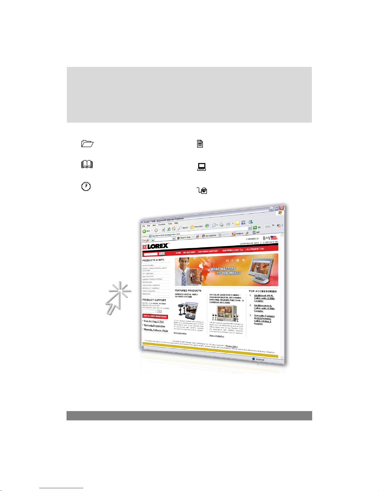
It’s all on the web
Product Information
User Manuals
Quick Start Guides
Specification Sheets
Software Upgrades
Firmware Upgrades
VISIT
www.lorexcctv.com
Lorex Technology Inc.
www.lorexcctv.com
 Loading...