

Page 1
5” B&W Rear View
System Camera
Instruction Manual
MODEL:
CA453
Copyright © 2007 LOREX Technology Inc.
www.lorexcctv.com
Page 2
Thank you for purchasing the Lorex 5” Black & White Rear View System Camera. This
system helps to prevent backing-up and parking accidents by allowing you to view or
check on the traffic behind your vehicle, or when rounding corners (blind spot
prevention).
This system is suitable for waste trucks, RV campers, vans, delivery vehicles &
cars.To learn more about this system or to find out more about our products available,
please visit our website at:
http://www.lorexcctv.com
CAUTION
RISK OF ELECTRIC SHOCK
DO NOT OPEN
CAUTION: TO REDUCE THE RISK OF ELECTRIC SHOCK
DO NOT REMOVE COVER (OR BACK).
NO USER SERVICEABLE PARTS INSIDE.
REFER SERVICING TO A QUALIFIED SERVICE PERSONNEL
The lightning flash with arrowhead symbol, within an
equilateral triangle, is intended to alert the user to the
presence of uninsulated “dangerous voltage” within the
product’s enclosure that may be of sufficient magnitude
to constitute a risk of electric shock to persons.
The exclamation point within an equilateral triangle is
intended to alert the user to the presence of important
operating and maintenance (servicing) instructions in
the literature accompanying the appliance.
WARNING: TO PREVENT FIRE OR SHOCK HAZARD,
DO NOT EXPOSE THIS UNIT TO RAIN OR MOISTURE.
CAUTION: TO PREVENT ELECTRIC SHOCK, MATCH WIDE BLADE
OF PLUG TO WIDE SLOT, FULLY INSERT.
Warning: This Rear Observation System is to be used with, not instead of, other
viewing aids in your vehicle such as front, rear, and side mirrors. Safe driving
practices, alertness, and visual and physical fitness are prerequisites for your driving
safety. The Manufacturer shall not be held liable for any accidents which may occur
2
while operating this system.
Page 3

General Precautions
NOTE
This equipment has been certified and found to comply with the limits regulated by FCC, EMC, and LVD. Therefore, it
is designated to provide reasonable protection against interference and will not cause interference with other appliance
usage.
However, it is imperative that the user follows this manuals guidelines to avoid improper usage which may result in
damage to the unit, electrical shock and fire hazard injury
In order to improve the feature functions and quality of this product, the specifications are subject to change without
notice from time to time.
FCC CLASS B NOTICE
Note:
This equipment has been tested and found to comply with the limits for a Class B digital device, pursuant to Part
15 of the FCC Rules. These limits are designed to provide reasonable protection against harmful interference in
a residential installation. This equipment generates, uses, and can radiate radio frequency energy and, if not installed and used in accordance with the instruction, may cause harmful interference to radio communications.
However, there is no guarantee that interference will not occur in a particular installation. If this equipment does
cause harmful interference to radio or television reception (which can be determined by turning the equipment on
and off), the user is encouraged to try to correct the interference by one or more of the following measures:
z Reorient or relocate the receiving antenna
z Increase the separation between the equipment and receiver
z Connect the equipment into an outlet on a circuit different from that to which the receiver is
connected
z Consult the dealer or an experienced radio or television technician for assistance
General Precautions
1. All warnings and instructions of this manual should be followed
2. Remove the plug from the outlet before cleaning. Do not use liquid aerosol detergents. Use a water dampened cloth
for cleaning
3. Do not use this unit in humid or wet places
4. Keep enough space around the unit for ventilation. Slots and openings in the storage cabinet should not be blocked
5. During lightning storms, or when the unit is not used for a long time, disconnect the power supply, antenna, and cables
to protect the unit from electrical surge
LOREX TECHNOLOGY INC.
http://www.lorexcctv.com
3
Page 4

Table of Contents
Table of Contents
Getting Started .......................................................................................... 5
Camera Installation ................................................................................... 5
Mounting the Cameras and Cables .......................................................... 6
Camera Overview ..................................................................................... 6
Full Connection Diagram .......................................................................... 7
Operating Instructions ............................................................................... 7
Camera Specifications - Appendix #1 ....................................................... 8
Lorex CVA453 Accessory Cables - Appendix #2....................................... 9
CA453 FEATURES
• Automatic switching of camera when gear is shifted into reverse
• Built-in microphone on camera (One-way audio).
• Waterproof, light sensitive, CCD sensor camera in a compact die-cast housing
• Wide Field of View: 94°Horizontal 72°Vertical 110°Diagonal
• 2 piece Waterproof Camera connecting cable (prevents corrosion & resistant to weathering)
with 4 pin connector
4
Page 5

Getting Started
The CA453 Camera comes with the following components:
65’ (2 Piece) Camera Extension Cable1/3” CCD Weatherproof Camera
Getting Started
CHECK YOUR PACKAGE TO CONFIRM THAT YOU HAVE RECEIVED THE COMPLETE
SYSTEM, INCLUDING ALL COMPONENTS SHOWN ABOVE.
Camera Installation
1. Connect the 1.8 M cable from the camera to the short 5M piece of the 20M (15M + 5 M) 2-piece
extension cable provided.
2. Connect the other end of the 5M cable to the 15M piece, which connects to CAM 1 or CAM 2
on the back of the monitor
5
Page 6

Mounting the Cameras and Cables
Mounting the Cameras and Cables
1. Determine the desired camera mounting position. Install the bracket into position using the
supplied screws on the center and slide holes.
2. Adjust the bracket to the left and right to set the position, and tighten the screws.
3. Install the camera to the bracket using the supplied washers, spring washers and screws.
4. Adjust the camera to the desired position (make sure the picture is clear and pointed in the
correct direction). Tighten the screws.
5. Drill a cable entry hole through the frame, door or window frame just below the mounting bracket.
6. Pull the cable fully through the hole. Once the cable has been pulled through, attach the extension
cable to the camera.
7. Run the extension cable to the Monitor.
8. Shield the hole that you made for the cable.
NOTE: Do NOT connect the camera(s) to the monitor while the system is powered on. Failure to
properly connect the cameras may cause damage and invalidate the warranty.
Camera Overview
6
Page 7

Full Connection Diagram
Full Connection Diagram
1. Connect the RED wire to the (12V – 32V DC) power terminal, which powers the system when
the ignition key is turned on the vehicle.
2. Connect the BLACK wire to a metal portion of the vehicle or the negative battery post.
3. Connect the BROWN wire to the switched power output terminal of the “R” (reverse) gear.
4. Connect the WHITE wire to the Dimmer line.
Operating Instructions
• When you turn the ignition key to the ON position, power is supplied to the monitor. The
monitor will automatically be in standby mode, even if the Power button is not pushed in.
• When you push the power button you can manually view the picture from the camera(s).
• When the power button is not pushed in, and you shift the gear into reverse, the monitor will
automatically display the image from selected Camera (if the Auto/Manual switch is in the
AUTO position).
7
Page 8

Camera Specifications - Appendix #1
Camera Specifications - Appendix #1
Pick-up Device
1/3” B&W CCD
Number of Pixels 512 x 492 (EIA)
Fixed Focus Lens 2.5mm
Viewing Angle 110
Horizontal Resolution 380 TV Lines
Video Output 1V p-p, 75 ohms
Minimum Illumination
Shock / Vibration Rating 6.8g @ 0~2000 Hz
Input Voltage Range 9.5~14V DC from the monitor
Operating Temperature 14°F ~ 122°F
Dimensions 2.76” (W) x 1.97” (H) x 1.97” (D)
Weight 0.75 lbs / 0.34 kg
° Diagonal
0.3 Lux
-30
°C ~ 50°C
70mm (W) x 50mm (H) x 50mm (D)
As our products are subject to continuous improvement, LOREX Technology Inc. and its
subsidiaries reserve the right to modify product design, specifications and prices, without notice
and without incurring any obligation. E&OE
8
Page 9
Lorex CVA453 Accessory Cables - Appendix #2
Lorex CVA453 Accessory Cables - Appendix #2
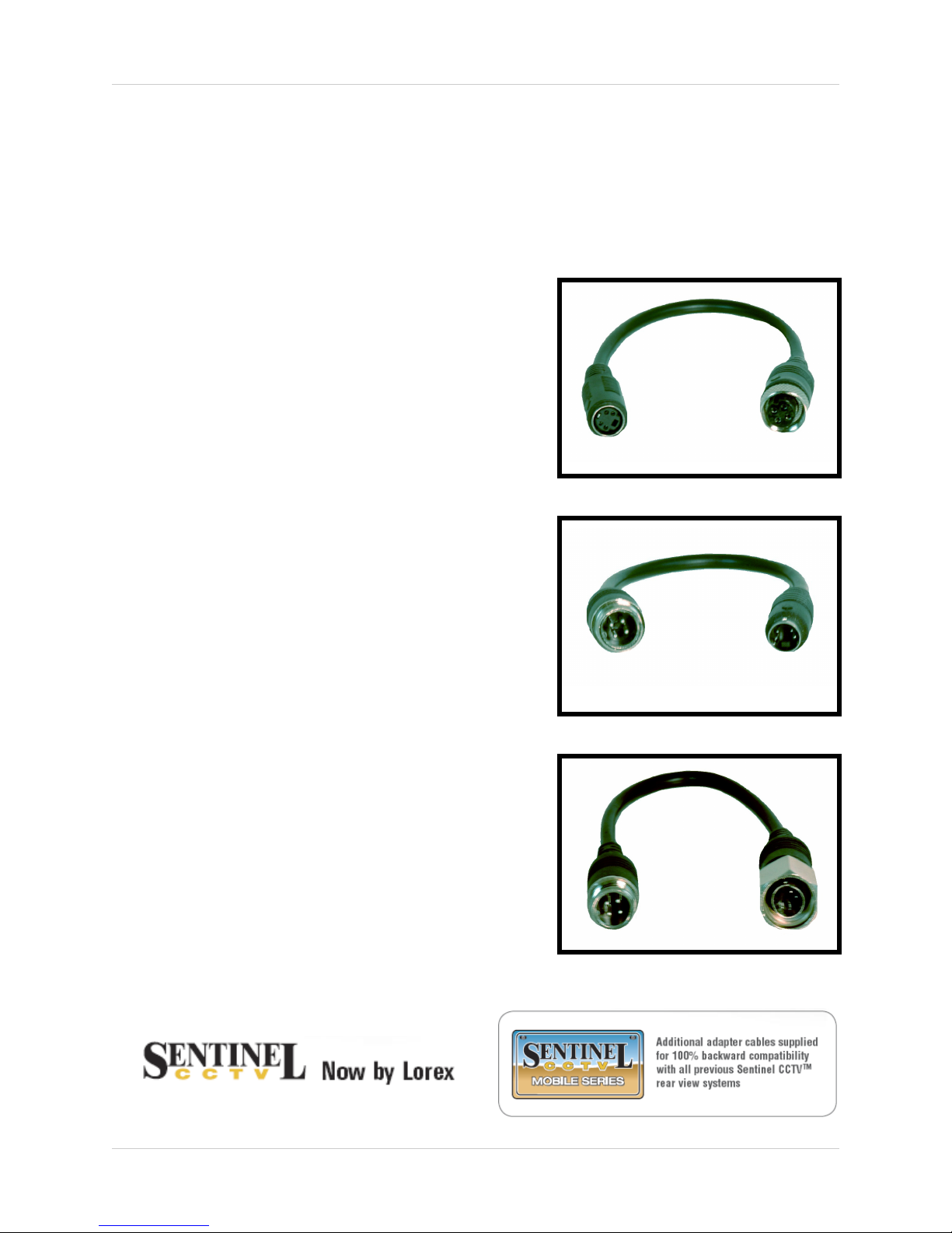
Additional adapter cables are available for backward compatibility between the Lorex 452 Series
and the Sentinel CCTV 452 Series Rear view systems.
Adaptor Cable #1 - CA452 (Camera
Extension Cable) to MO453 (Monitor)
Connects the Sentinel CA452 Camera Extension
Cable to the Lorex CA453 Monitor.
Adaptor Cable #2 - CA453 (Camera
Extension Cable) to MO452 (Monitor)
Connects the Lorex CA453 Camera Extension
Cable to the Sentinel MO452 Monitor.
Adaptor Cable #3 - CA453 (Camera) to
CA452 (Camera Extension Cable)
Connects the Lorex CA453 Camera to the Sentinel
CA452 Camera Extension Cable.
9
Page 10

It’s all on the web
Product Information
User Manuals
Quick Start Guides
Specification Sheets
Software Upgrades
Firmware Upgrades
VISIT
www.lorexcctv.com
Lorex Technology Inc.
wwwlorexcctv.com
 Loading...