

Page 1
MODEL ACCL224VGA
VGA CONVERTER ACCESSORY
(For L224 Series DVR Only)
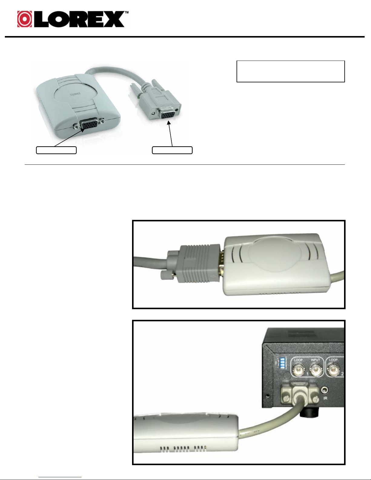
VGA Converter
To Monitor To DVR
INSTALLATION / PLACEMENT
1. Turn off the DVR BEFORE connecting the VGA Converter.
2. Connect the VGA Connector
Cable from the PC Monitor to the
VGA Port on the VGA Converter
Accessory.
THIS PACKAGE CONTAINS:
1 – VGA Converter for L224
Series DVR
FEATURES
• Allows the L224 Series DVR
to be connected to a PC
Monitor
• Converts the signal to VGA
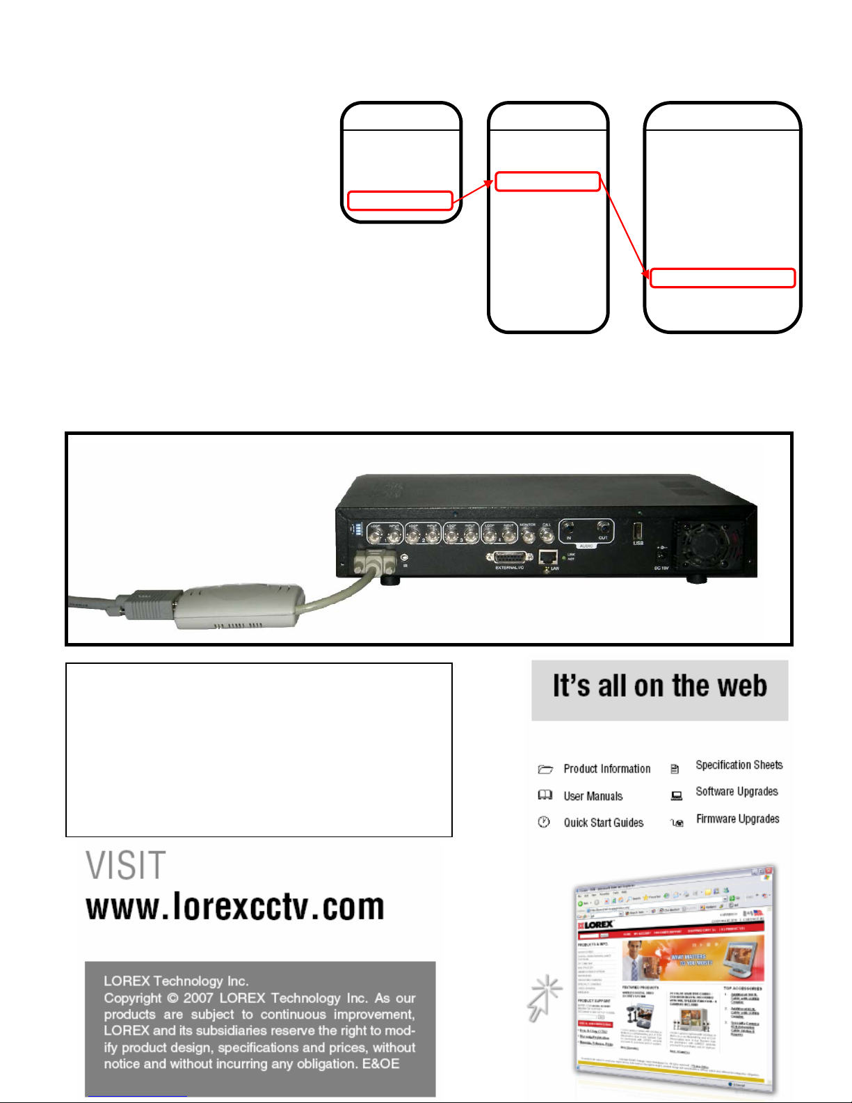
3. Connect the VGA
Converter Accessory to the
L224 Series DVR using the
D/V Port.
Page 2
4. Turn on the DVR. Press MENU (on the front panel of the DVR), and enter the DVR PASSWORD (0000
by default). Navigate to the Monitor Setup on the DVR:
• Use the ▲▼◄► keys to navigate.
•Press ENTER to select a menu,
and MENU to exit.
• Press the +/- keys to change the
settings in a menu.
• Select ADVANCED from the Main
Menu.
• Select DISPLAY from the
Advanced Menu
• Navigate to the MONITOR OUT
option, and use the +/- keys to set
the option to VGA. Save the
settings, and exit the Menu.
FULL SETUP DIAGRAM
MENU
Record
Timer
Date
Advanced
ADVANCED
Camera
Detection
Display
Alert
Remote
System
Network
Backup
HDD Info
Event Log
NOTE: If the MONITOR OUT setting is not changed to VGA (set to
MAIN by default), the motion detection area setting will be disabled.
DISPLAY
Title Display
Date Display
HDD Info
Loss Screen
Playback Info
Dwell Duration
De-Interlace
Monitor Out
OSD
Watermark
ON
ON
ON
BLUE
NORMAL
2
ON
VGA
SETUP
ON
SPECIFICATIONS
Connection: DVR Side: D-SubLCD
Monitor Side: D-Sub
Function: 1. Output Resolution up to 1024x768@60Hz
2. Analog non-interlaced RGB Output Supported
3. NTSC / PAL System Auto Detection
Power: Powered by DVR
Power Consumption: 2W
Dimensions (W x D x H): 2.6” x 3.4” x 0.9”
65mm x 87mm x 24mm
 Loading...