

Page 1
INSTRUCTION MANUAL
12” B&W 4 CHANNEL OBSERVATION SYSTEM
SEE WHAT YOU’’
SEE WHAT YOU
BEFORE OPERATING THIS UNIT, PLEASE READ THIS MANUAL THOROUGHLY AND
RETAIN IT FOR FUTURE REFERENCE
VE BEEN MISSING
VE BEEN MISSING
Page 2
BEFORE OPERATING THIS SYSTEM, PLEASE READ
THIS MANUAL THROUGHLY AND RETAIN IT FOR
FUTURE REFERENCE
Thank you for purchasing the 12” B&W 4 Channel Observation system .
LOREX is committed to providing our customers with a high quality, reliable
security product that customers have come to expect from us.
To learn more about this 12” B&W 4 Channel Observation system and to learn
about our complete range of accessory products, please visit our website at:
www.strategicvista.com
CAUTION
!
RISK OF ELECTRIC SHOCK. DO NOT OPEN.
CAUTION! TO REDUCE THE RISK OF ELECTRIC SHOCK, DO NOT REMOVE
COVER (OR BACK). NO USER-SERVICEABLE PARTS INSIDE.
REFER SERVICING TO QUALIFIED SERVICE PERSONNEL.
Explanation of two Symbols
The lightning flash with arrowhead symbol, within an equilateral
triangle, is intended to alert the user to the presence of un-insulated
dangerous voltage" within the product's enclosure that may be of
sufficient magnitude to constitute a risk of electric shock to persons.
The exclamation point within an equilateral triangle is intended to
alert the user to the presence of important operating and maintenance-
!
(servicing) instructions in the literature accompanying the appliance.
THE GRAPHIC SYMBOLS WITH SUPPLEMENTAL MARKING ARE ON
THE BOTTOM OF THE SYSTEM.
“WARNING – TO PREVENT FIRE OR SHOCK HAZARD, DO NOT EXPOSE
THE UNIT TO RAIN OR MOSITURE”
-i -
Page 3

NOTE
This equipment has been certified and found to comply with the limits regulated by
FCC, EMC and LVD. Therefore, it is designed to provide reasonable protection
against interference and will not cause interference with other appliance usage.
However, it is imperative that user follows this manual's guidelines to avoid improper
usage which may result in damage to the unit, electrical shock and fire hazard or
injury.
In order to improve the feature functions and quality of this product, the specifications are subject to
change without notice from time to time.
FCC CLASS B NOTICE
Note:
This equipment has been tested and found to comply with the limits For a Class B digital
device, pursuant to Part 15 of the FCC Rules. These limits are designed to provide
reasonable protection against harmful interference in a residential installation. This
equipment generates, Uses and can radiate radio frequency energy and, if not installed and
used in accordance with the instruction, may cause harmful interference to radio
communications. However, there is no guarantee that interference will not occur in a
particular installation. If this equipment does cause harmful interference to radio or
television reception, (which can be determined by turning the equipment off and on), the user
is encouraged to try to correct the interference by one or more of the following measures:
• Reorient or relocate the receiving antenna.
• Increase the separation between the equipment and receiver.
• Connect the equipment into an outlet on a circuit different from that
to which the receiver is connected.
• Consult the dealer or an experienced radio or television technician for
help.
STRATEGIC VISTA CORP.
www.strategicvista.com
-ii-
Page 4

CONTENTS
1. GENERAL PRECAUTIONS --------------------------------------------------------------------- 2
2. CAUTIONS AND FEATURES ----------------------------------------------------------------- 3
3. SYSTEM --------------------------------------------------------------------------------------------- 4
4. MONITOR CONTROLS - FRONT PANEL ------------------------------------------------- 5
5. ON-SCREEN-DISPLAY OPERATION ------------------------------------------------------ 7
6. MONITOR CONTROLS - BACK PANEL ---------------------------------------------------- 9
7. REMOTE CONTROL ----------------------------------------------------------------------------- 10
8. STANDARD B&W -------------------------------------------------------------- 11
9. MONITOR CONNECTIONS ------------------------------------------------------------------ 12
10. TROUBLE SHOOTING --------------------------------------------------------------------- 12
11. TECHNICAL SPECIFICATIONS ----------------------------------------------------------- 13
12. OPTIONAL ACCESSORIES ---------------------------------------------------------------- 14
13. APPENDIX - A ALARM CONNECTION -------------------------------------------------- 15
14. APPENDIX - B CONNECTING MONITOR TO A VCR ------------------------------- 16
15. APPENDIX - C WIRING CONNECTION. -------------------------------------------------- 17
16. APPENDIX - D CONNECTING TO A LOREX TIME LAPSE VCR
FOR NORMAL REC.--------------- 18
17. LOREX PRODUCT WARRANTY ------------------------------------------------------- 19
18. CARE AND MAINTENANCE ----------------------------------------------------------------- 20
-1-
Page 5

GENERAL PRECAUTIONS
1. Read Instructions
All of the safety and operating instructions should
be read and understood before the product is used.
2. Retain Instructions
The safety and operating instructions should be
retained for future reference.
3. Heed Warnings
All warnings on the product and the instruction
manual should be followed.
4. Follow Instructions
All operating and use instructions should be followed
for optimal performance
5. Cleaning
Disconnect this video product from the power supply
before cleaning
6. Attachments
Do not use attachments not recommended by the
video product manufacturer as they may cause
hazards.
7. Water and Moisture
Do not use this product near water - for example,
near a bathtub, wash bowl, kitchen sink, wet
basement, or near a swimming pool.
8. Accessories
Use this product only with a stand, tripod, bracket or
table recommended by the manufacturer or sold
with the product. Any mounting of the product
Should follow the manufacturer’s instructions.
9. Ventilation
This product should never be placed near or over a
Radiator or heat register. This product should not be
Placed in a built-in installation, such as a book case
Or rack, unless proper ventilation is provided or the
Manufacturer’s instructions have been adhered to.
10. Power Source
This product should be operated from the type of
Power source indicated by the marking label. If you
Are not sure of the type of power supply to your
Location, consult your product dealer or your local
Power company
11. Power Cord Protection
Power supply cords should not be routed so that they
Are likely to be walked on or pinched by items placed
On or near them
12. Lightning
For added protection, unplug this product from its
outlet during a lightning storm. This will prevent
damage to the video product due to lightning and
power surges
13. Overloading
To avoid the risk of fire and electric shock, do not plug
this video product into an over-loaded power supply
14. Object and Liquid Entry
Never push objects into the openings of this product
as they may touch dangerous voltage points that
may result in fire or electric shock. Never spill a liquid
of any kind on this product.
15.Servicing
Do not attempt to service this product yourself
as opening or removing covers may expose
you to voltage or other hazards. Refer all
servicing to qualified service personnel
16.Damage Requiring Service
Disconnect this product from the power supply
and refer servicing to qualified service
personnel under the following conditions:
a. When the power supply cord or plug is damaged
b. If objects have fallen into the product
c. If the product has been exposed to rain or liquids
d. If the product does not operate normally by
following the instruction manual. Adjust only
the controls that are covered in the
instruction manual as an improper
adjustment may result in damage and will
often require extensive work by a qualified
service technician to restore the product
to its normal operation
e. If the product has been dropped or the
cabinet has been damaged
f. When the product displays a distinct change
in performance - this indicates a need for service
17. Replacement Parts
When replacement parts are required, be sure
the technician uses replacement parts
specified by the manufacturer. Unauthorized
substitutions may result in fire, electric shock,
or other hazards
18. Safety Check
Upon completion of any service to this product
ask the service technician to perform safety
checks to determine that the product is in
proper working condition
-2-
Page 6

CAUTIONS
1. All the warnings and instructions of this manual should be followed
2. Remove the plug from the outlet before cleaning. Do not use liquid aerosol detergents.
Use water damped cloth for cleaning
3. Do not use this unit in very humid and wet places
4. Keep enough space around the unit for ventilation. Slots and openings of the cabinet
should not be blocked.
5. During flashes of lightning or cracks of thunder, or when the system is not used for a
long time, unplug the system power supply and disconnect the antenna and cables to
protect the unit from lightening or power surges.
FEATURES
Monitor Features:
• Metal cabinets with 4 camera inputs.
• Auto switching – up to 4 cameras.
• Multi-voltage system 100 – 240Volts
• High-resolution metal cabinet monitor
• Selectable dwell time (alarm and sequential)
• Remote Control or main panel operation
• ON/OFF power switch allows monitor to be turned off while recording
• Sequentially rotate through full screen display of each camera location
• One camera full screen viewing
• Built in speaker and microphone for two way audio communication.
• Monitor with CCD’s show system status.
Standard Camera Features
•1/3’’CCD B/W Camera
• Built in speaker and microphone to allow for two way audio communication
• PIR sensor detects movement and triggers monitor to full-screen display
• Metal mounting bracket.
• Camera with built on Auto iris automatically adjusts camera to different lighting conditions.
• Camera with infrared CCD’s ideal for low light conditions.
-3-
Page 7

SYSTEM INCLUDES
12” B&W 4CHANNEL MONITOR
B/W PIR MOTION SENSOR CAMERA
(MODEL SG7011SX – 4 CAMERAS
4-65 Ft CABLE
INCLUDED
AND 4 METAL STAND INCLUDED)
(1 Camera included with model
SG1241 & 2 with SG1242)
(1 Cable included with
model SG1241 & 2
with SG1242)
-4-
Page 8
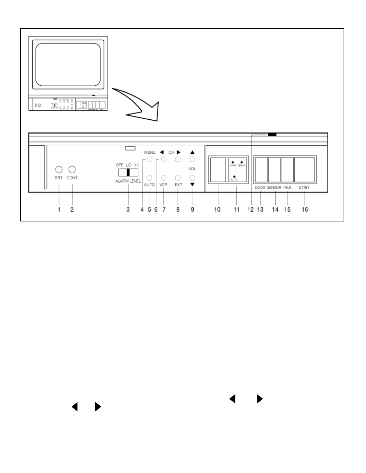
MONITOR CONTROLS - FRONT PANEL
1. Brightness Control - Adjusts brightness of picture.Turn knob to reach desired brightness
level.
2. Contrast Control - Adjusts contrast of picture. Turn knob to reach desired contrast level.
3. Alarm control button – The sound level of alarm can be adjusted in three levels as desired.
Alarm Off - Mutes the alarm.
Alarm Low - sounds a low volume alarm.
Alarm High - sounds high volume alarm
4. Menu button – Press and hold the menu button for more than 2 seconds to access the
on -screen display feature.
5. Automatic camera channel sequencing – If two or more camera are installed on same
monitor, this operation rotates between cameras 1-2-3-4.
6.Channel selection buttons-There are four buttons marked and .
Press the or button to view the desired channel. The monitor moves from
one camera to another.
-5-
Page 9

7. VCR button – This button will change the display from the camera inputs to the VCR
audio/video playback and recording signal.Note:The surveillance system is designed to work on
a professional Time lapse VCR only.
8. Extra button – The button will change the display from the camera inputs to the EXTRA camera
signal installed in BNC Jack on rear panel.
9. Volume Control - Controls the Volume. Press or to reach the desired volume level.
10. Microphone – Picks up sound around the monitor.
11. Remote Sensor – The monitor can be operated by remote control. Refer to page 10 of the
manual for more details.
12. Display Board – Indicates the channel or mode the monitor is set to .Note a dot appears at the
Bottom right to indicate that the monitor is set to auto mode.
13. Door Open – Pressing this switch will unlock a door installed through door-lock terminal
located at the back of the unit.
14. Alarm ON/OFF(ALRS) – This button acts as an auxiliary alarm button.The main setting is
controlled with the Alarm mode OSD setting (Alarm:Buzzer+OSD/OSD/OFF).If motion is
detected at a camera, press the ALRS button to turn OFF the reset in the Alarm mode
setting.To deactivate the alarm function press this button twice.Note:If the OSD Alarm setting is
set to OFF, the ALRS button will not work.
15. Talk button – Users can talk to the specific camera location by pressing and holding the talk
button.The talk button must be pressed the entire time ,while talking.To listen to camera
location release the talk button.
16. Power switch – Pressing this switch will turn ON the monitor.Pressing it again will turn the
power OFF.The master power switch ,which controls the monitor is located at the back of
the unit.
-6-
Page 10

LOSS/ALARM
HISTORY 1PAGE
L CH1 2002/01/0103:19:48
L CH2 2002/01/0203:19:48
L CH3 2002/01/0403:19:48
L CH4 2002/01/0403:19:48
PUSH MENU KEY
PERATION
SYSTEM SET UP
1. CHANNEL NAME
2. TIME / DATE
3. DISPLAY MODE
4. ALARM MODE
5. SEQUENCE
6. ALARM HISTORY
7. EXIT
SEQUENCE
CH1 02SEC
CH2 02SEC
CH3 02SEC
ALARM MODE
ALARM RESET TIME : 05SEC
BEEP TIME:15 SEC
ALARM : BUZZER+OSD/
DATE/TIME/OFF
DISPLAY MODE
E/TIME : DATE+TIME/
TION : R/L
CH4 02SEC
PUSH
OSD / OFF
VIDEO LOSS : BUZZER+OSD/
DD/MM/YY
: YY/MM/DD
MENU KEY
OSD / OFF
CAMERA1 : ON/OFF
CAMERA2 : ON/OFF
CAMERA3 : ON/OFF
MM/DD/YY
CAMERA4 : ON/OFF
PUSH MENU KEY
ON – SCREEN – DISPLAY O
DAT
TIME / DATE
02/14/2002 14:00
CH1 CHANNEL1
CHANNEL NAME
CH2 CHANNEL2
POSI
CH3 CHANNEL3
TYPE
CH4 CHANNEL4
LOSS POSITION : L/R
CHANNEL NAME : L/R
CH1 CHANNEL1
PUSH MENU KEY
0 ~ 9
A ~ Z
-7-
Page 11

1. Channel name set – This option allows the user to title each of the four camera locations.
A total of 8 letters / characters can be used. Use the Volume and channel control buttons
on the control panel to move and set the titles or to save these settings move the cursor to
the EXIT button and press the Menu button.You can also use the Remote control to set
the Title. Use the same volume, channel and menu button on the Remote control.
2. Time and date set – This option allows for the time and date to be adjusted .The date is
displayed as DD/MM/YY.Use the volume and channel control button on the monitor to
change the date,month,year and time.Once finished press the menu button to save and
exit.The channel ,volume and menu buttons on the remote control can also be used to set
the Time and Date.
3. Display mode set – This option allows the user to adjust the OSD options.
a.Date /Time: Use this button to select the DATE, DATE+TIME or OFF.In the OFF setting
the OSD setting is disabled.
b.Position :Displays the positioning of the DATE/TIME/CAMERA tilting.
c.Type:Displays the order of MONTH/DATE/YEAR
d.Loss Position: Displays Video loss warning(when there is a camera loss)
e.Channel name: Displays the positioning or the camera tilting.
4. Alarm Mode – This option sets different alarm settings.
a. Alarm reset time: Adjusts the alarm duration from 0-60 seconds.After the set time the
system will go back to the previous setting.
b. Beep time:Adjusts the ‘beep’ warning time from 0-60 seconds.
c. Alarm:The alarm can be set to OFF/OSD/OSD+ BUZZER.If just OSD is selected then
the alarm if triggered, will be displayed only on the monitor.
d. Video loss: If there is a picture loss in the camera the system will notify you. Select
between OFF/OSD/OSD+BUZZER option.
5. Sequence – This function is used when monitor is set to auto mode.In Auto sequence
mode the monitor will automatically sequence from cameras 1-4.Adjust the dwell duration
from 0-60 seconds.
6. LOSS/ALARM: If there is a loss of video due to some problem then the time,date and
location of the loss is displayed.
-8-
Page 12

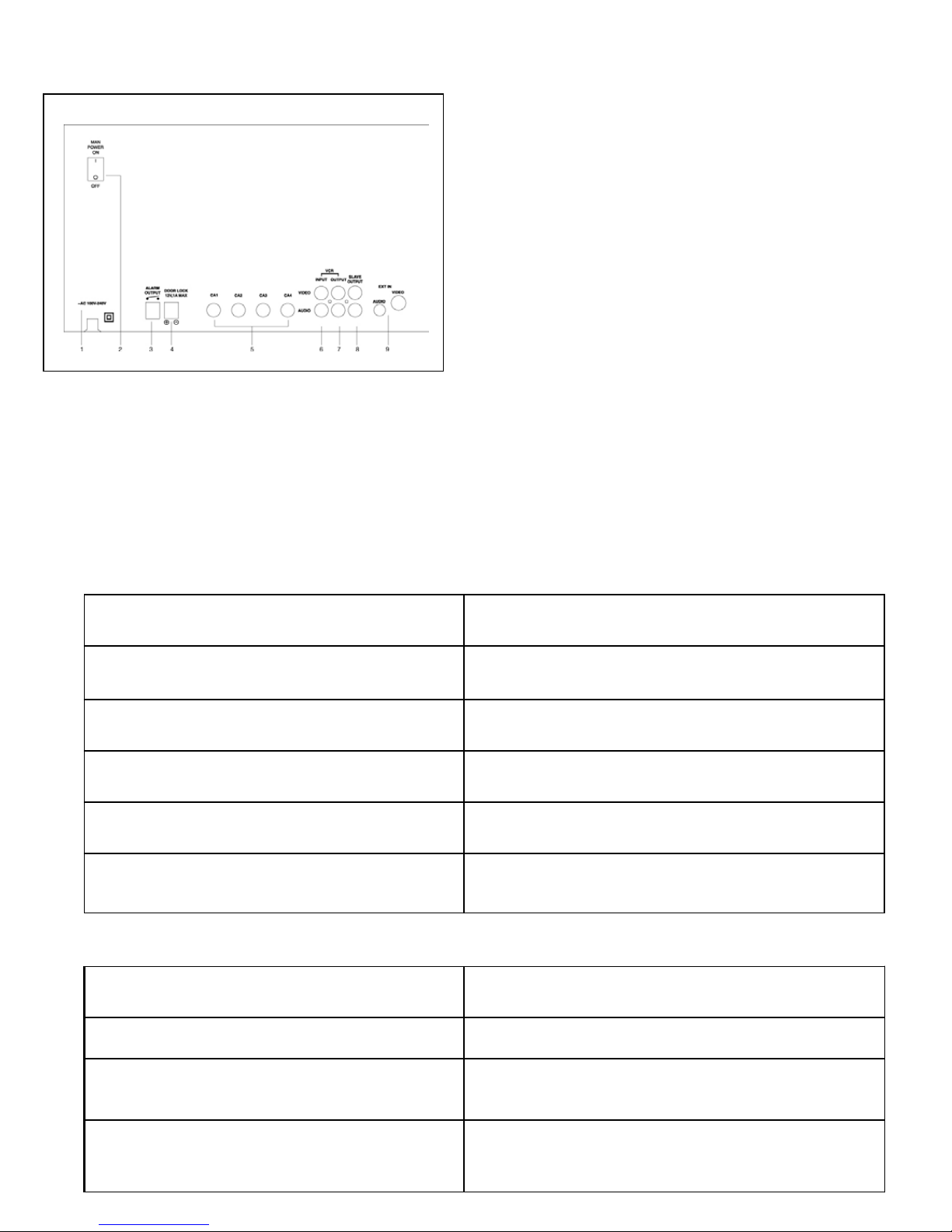
MONITOR CONTROLS - BACK PANEL
1. AC Input - This Cord is used to connect the supplied power cord from the monitor to an
electrical outlet. AC 100V ~ 240V, 50/60Hz.
2. Power Switch(main power switch) - This button controls power to the entire unit.
Depress the side with the ‘I’, to turn power ON. Depress the ‘O’ side to turn the unit OFF.
3. Alarm Output - To use the VCR, connect Alarm Output with Trigger-In & Ground of VCR.
When sensor is detected, the picture will be automatically recorded on the VCR.
4. Door Lock - Connect Door Lock to this terminal with normal wires (not supplied).
5. 6 Pin Din Camera Inputs - Channel 1-4 camera inputs (for camera switch 6 pin din camera
Inputs)
6. VCR Audio/Video In - Use with A/V cables (not supplied) to receive audio & Video from
an V.C.R
7. Audio/Video Out - Use with A/V cables (not supplied) to transmit audio & Video from
the monitor.
8. Slave Audio/Video Output – Use with A/V cables (not supplied) for use with a slave
monitor
9. Extra Audio/Video In – Connect Extra camera video signal to BNC plug and audio signal
to RCA plug.
-9-
Page 13

REMOTE CONTROL
Listed below are the features of the Remote Control. For more details on specific remote
control features, refer to the Monitor feature section.
FUNCTION DESCRIPTIONKEY
ST/BY
VCR
ALRE
Turns monitor ON / OFF
Sets monitor to VCR Mode
Sets OFF the alarm or sets it
ON.
EXT
Select extra camera
DOOR Unlock a door
AUTO
Auto sequence.
Allows the user to Change
Helps to increase or reduce the
channels
volume
-10-
Page 14

STANDARD B&W
Camera Lens - Delivers high quality image by using a 1/3’’ CCD Image Sensor
Microphone - Picks up sound around the camera
Camera Inputs - Connects cable to monitor
Speaker - Delivers sound from the monitor to the camera
Bracket - Metal bracket connects to camera for mounting to walls, ceilings or table
PIR Sensor - Detects movement / motion.
Sensor Input - Connects PIR Sensor to cameras
External Speaker Jack - Allows user to connect external speaker to camera
INSTALLATION
A. Camera Unit
Permanent installation using metal camera bracket
IMPORTANT NOTE:
Keep camera installed away from direct sunlight. Also avoid places where humidity
is high or unable to protect rain. The mounting bracket must be attached to a structural
device such as wall stud or ceiling rafter using suitable fastener.
-11-
Page 15
MONITOR CONNECTIONS
1. Camera 1 input
Connect one end of the supplied 65ft cable to
the first wired camera and the other end to the
camera 1 input
2. Camera 2 input
Connect one end of the supplied 65ft cable to
the first wired camera, the other end to camera
2 input
3. Camera 3 input
Connect one end of the supplied 65ft cable to
the second wired camera, the other end to
camera 3 input
4. Camera 4 input
Connect one end of the supplied 65ft cable to
the third wired camera, the other end to
camera 4 input
TROUBLE SHOOTING
If the system does not function properly, please check the following points.
MONITOR
PROBLEM REMEDY
Too dark or bright picture Readjust the CONTRAST or BRIGHTNESS controls
NO POWER Check AC connection
Picture but no sound Adjust the VOLUME control
Shrinking picture Check the condition of the POWER source
Poor picture quality Clean the camera lens. Readjust the CONTRAST
or BRIGHTNESS controls
CAMERA
Picture Flickering or Over Exposed
Motion sensor not working
REMEDYPROBLEM
Check the cable for any lose connectionNo Picture
Make sure the camera is not facing any direct light
or Sunlight
Check the connections from the PIR to the camera
-12-
Page 16

TECHNICAL SPECIFICATIONS
MONITOR
Picture Tube 12” B&W
Horizontal resolution 600 lines
Camera Capable Up to four (4 DIN)
Camera Input 4 6 pin DIN
Control power, seq, Talk, VCR, brightness,
Contrast,volume,time,alarm set.
Input signal 1 V p-p at 75 ohms terminated
Power Source Multi-voltage (AC100V – 240 V)
Power Consumption 40 watts
Operating Temperature 32ºF 104°F (0° C – 40°C)
Color White – Metal cabinet
STANDARD CAMERA
Image Device 1/3” CCD image sensor
Resolution 380 TV Lines
Shutter control Auto 1/60 - 1/100,000
Power requirement Powered from monitor via cable
Operating Temperature 14°F – 122°F (-10°C to 50°C)
Weight: 12 oz (340 Grams)
Dimensions: 2.76” (W) x 3.35”(D) x 2.90”(H)
(7.0cm (W) x 8.5cm (D) x 5.3cm(H))
Housings: White
Because our product are subject to continuous improvement, SVC reserves the right to modify product design and specifications without
notice and without incurring any obligation. E&OE
-13-
Page 17

OPTIONAL ACCESSORIES
The following accessories are available to add to your existing system.
CABLE TIME LAPSE RECORDER
Extends viewing length from
Camera to monitor. Available
In 65, 100 and 250 ft lengths
NIGHTVISION
24 Hour Real Time or 960 Hour
Time Lapse VCR. Records key
events
ACCESSORY SUNSHADE HOUSING
FOR OBSERVATION SYSTEM CAMERAS
Weatherproof Nightvision
accessory. Allows you to
see in the dark up to 3540ft distance (for use with
Observation system
cameras)
For a complete listing of available
Accessory Sunshade Housing -Protects
camera from weather elements.
Accessories visit
www.strategicvista.com
-14-
Page 18

APPENDIX - A
PIN SPECIFICATION OF CABLE
PIN
1
2
3
4
5
6
7
COLOR
WHITE
BLACK
BLUE
GREEN
RED
YELLOW
‘SHIELD’
DESCRIPTION
VIDEO SIGNAL
AUDIO(monitor to camer)
N.C.
AUDIO B+
AUDIO(monitor to camer)
AUDIO B+
GROUND
TO PIR SENSOR
PROCEDURE
Connection PIR SENSOR to Camera sensor terminal.
NOTE
Ensure correct connections.
-15-
Page 19
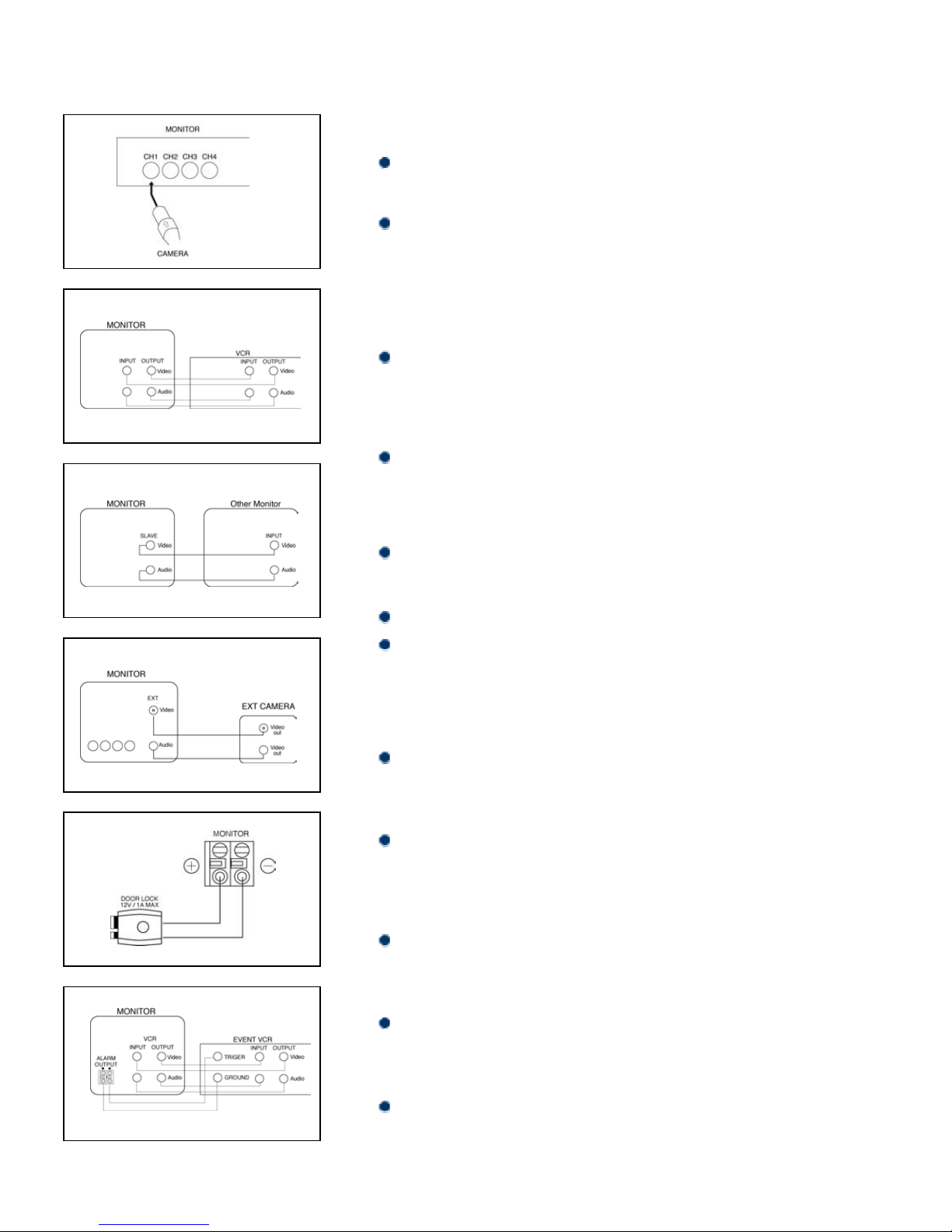
APPENDIX - B
TO CAMERA CONNECTIONS
PROCEDURE
Connect Monitor to Cameras, using 6 pin din cable supplied.
NOTE
Each pin should match. So that the arrow marks are to the top
upside on the Din cable when connecting the cable to Monitor or
Camera terminal.
TO VCR CONNECTION
PROCEDURE
Connect Audio/Video out to VCR (Audio/Video IN PUT
Terminals) and Audio/Video Input to VCR (Audio/Video OUT PUT
Terminal) with RCA cables (not supplied).
NOTE
RCA cables not supplied
TO OTHER MONITOR CONNECTION
PROCEDURE
Connect two Monitor with RCA cable (not supplied).
NOTE
Each monitor should be supplied with separate power sources.
To see same picture through another Monitor, press VCR button on
the other Monitor
EXTRA CAMERA CONNECTION(OPTIONAL)
PROCEDURE
Connect extra Cameras to Monitor terminal with normal wire (not
supplied).
NOTE
In case of Audio built-in, connect Audio line to Monitor terminal with
RCA cables(not supplied).
TO DOOR LOCK
PROCEDURE
Connect Door lock to Monitor terminal with normal wire (not
supplied).
NOTE
Ensure correct polarity.
TO DOOR LOCK
PROCEDURE
Connect Event VCR to Monitor terminal with normal wire (not
supplied).
-16-
Page 20

APPENDIX - C
Connection Diagrams
PROCEDURES
1. Connect VCR & Slave Monitor (optional) to main Monitor with RCA cables (not
supplied).
2. Connect Camera to Monitor with 65ft DIN cable supplied.
(Connect PIR sensor to Camera terminal(optional))
3. Connect Extra Camera optionally with BNC plug (not supplied).
4. Connect Monitor to Door Lock optionally with normal wires (not supplied).
5. Connect Monitor to VCR (Normal VCR or Time lapse VCR) optionally with normal
wires (not supplied).
6. Plug AC Power code to outlet on the wall.
7. Put on Main power switch at the rear of the Monitor unit.
8. Put on Power(ST/BY) button on the front of the Monitor unit.
-17-
Page 21

APPENDIX - D
CONNECTING TO A LOREX TIME LAPSE VCR FOR NORMAL RECORDING
-18-
Page 22

LOREX PRODUCT WARRANTY
LOREX PRODUCT WARRANTY
Lorex warrants, to the original retail purchaser only (the “Purchaser”), that this item (the “Product”) is free from
manufacturing defects in material and workmanship, provided the Product is used in normal conditions and is
installed and used in strict accordance with the instructions contained in the Product’s Owner’s Manual. This
warranty shall be for the following warranty periods (the “Warranty Period”), commencing on the date the
Purchaser buys the Product at retail in an unused condition.
All Other Components: Parts and Labor - 1 Year (Warranted parts do not include
Video Heads: Parts and Labor - 90 days
Lorex’s obligations under this warranty shall be limited to the repair or replacement of any warranted parts found
by Lorex to be defective in the Product, or, in Lorex’s sole discretion, the replacement of the Product found be
Lorex to be defective. Any replacement parts furnished be Lorex in connection with this warranty shall be
warranted to the Purchaser for a period equal to the unexpired portion of Warranty Period for the Product.
Warranty Exclusions
This warranty does not apply to Bulbs, LED’s and Batteries supplied with or forming part of the product.
This warranty is invalidated if other than Lorex accessories are or have been used in or in connection with the
Product or in any modification or repair is made to the Product be other than a service depot authorized by Lorex.
This warranty does not apply to defects or damages arising by use of the Product in other than normal (including
normal atmospheric, moisture and humidity conditions) or by installation or use of the Product other than in strict
accordance with the instructions contained in the Product’s owners Manual.
This warranty does not apply to defects in or damages to the Product caused by (i) negligent use of the Product,
(ii) misuse or abuse of the Product, (iii) electrical short circuits or transients, (iv) Purchaser adjustments that are
not covered in the Owner’s Manual, (v) use of replacement parts not supplied by Lorex (vi) improper Product
maintenance, or (viii) accident, fire, flood or other Acts of God.
Lorex reserves the right to make change in design or to make additions to or improvements in its products without
incurring any obligation to modify any product which has already been manufactured.
This warranty is in lieu of other warranties, express or implied, and Lorex neither assumes nor authorizes any
person to assume for it any other obligation or liability in correction with the sale or service of the Product. In no
event shall Lorex be liable for any special or consequential damages arising from the use of the Product or
arising from the malfunctioning or non-functioning of the Product, or for any delay in the performance of this
warranty due to any cause beyond its control.
This warranty shall not apply to the appearance or accessory items including, but not limited to cabinets, cabinets
parts, knobs etc., and the uncrating, setup, installation or the removal and reinstallation of products after repair.
Lorex does not make any claims or warranties of any kind whatsoever regarding the Product’s potential, ability or
effectiveness to prevent minimize, or in any way affect personal or property damage or injury. Lorex is not
responsible for any personal damage, loss or theft related to the Product or to its use for any harm, whether
physical or mental related thereto. Any and all claims or statements, whether written or verbal, by salespeople,
retailers, dealers or distributors to the contrary are not authorized by Lorex, and do not affect this provision of this
warranty.
The purchaser may have other rights under state, provincial, or federal laws and where the whole or part of any
item of this warranty is prohibited by such laws, it shall be deemed null and void, but the remainder of the
warranty shall remain in effect.
Bulbs, LED’s and Batteries)
Obtaining Service
Should the Product require service under this warranty, the Purchaser must provide Lorex with a copy of his/ her
original, dated bill of sale, receipt or invoice, failing which Lorex will not perform any of its obligations under this
warranty. To claim on this warranty, proceed with the following steps.
1 Pack the Product in a well-padded sturdy carton.
2. i). If the unit was purchased in the United States
Include $US 12.00 for monitors and VCR’s and $8.00 for Cameras for postage and handling (send
check or money order, no cash please), along with a copy of your dated bill of sale, receipt, or
invoice, plus a description of the Product’s apparent malfunction and the telephone number where
you can be reached during the day. Return the unit to:Strategic Vista Corp., 203 Eggert Road,
Buffalo NY 14215
ii). If the unit was purchased in Canada
Include CDN $18.00 for monitors and VCR’s and $12.00 for Cameras for postage and handling
(send cheque or money order, no cash please), along with a copy of your dated bill of sale,
receipt, or invoice, plus a description of the Product’s apparent malfunction and the telephone
number where you can be reached during the day. Return the unit to:Strategic Vista Corp. 300
Alden Road, Markham, Ont. L3R 4C1
proceed as follows:
proceed as follows:
www.strategicvista.com
-19-
Page 23

CARE AND MAINTENANCE
Please follow the following instructions to ensure proper care and maintenance
of this system
Keep your monitor and camera dry. If it gets wet, wipe it dry immediately.
Use and store your unit in normal temperature environment. Extreme
temperatures can shorten the life of the electronic devices.
Handle the monitor carefully. Dropping it can cause serious damage
to the unit.
Occasionally clean the unit with a damp cloth to keep it looking new.
Do not use harsh chemicals, cleaning solvents, or strong detergents
to clean the unit.
Keep the unit away from excessive dirt and dust. It can cause
premature wear of parts.
-20-
 Loading...