

Lorentz PS2-150 Boost, PS2-150, PS2-200, PS2-600, PS2-1800 Manual For Installation And Operation
...
PS2-150 to PS2-4000
Solar Pumping System
Manual for Installation and Operation
Manuel d’installation et de fonctionnement
Manual de Instalación y Operación
EN
FR
The Solar Water Pumping Company
ES


ENGLISH

2
Introduction
Thank you for purchasing a LORENTZ pump system. LORENTZ has set a new standard for quality, efficiency and
durability in solar pumping.
Before you begin: All pump systems are equipped with nameplates, which contain all important data. Check the model
numbers of all the components of your system, verify that they are the items that you ordered and ensure that the packaging
is undamaged and complete. To allow best system performance and to avoid damage read and follow the installation
instructions carefully.
How to use this guide: This manual is for system installation only, follow it closely for a safe and durable installation.
The system layout must be planned beforehand. We advise using the LORENTZ COMPASS software for correct pump system
sizing.
SITES: We highly recommend registering the installation at SITES in LORENTZ partnerNET. SITES provides an easy overview
of all installed pump systems, including serial numbers and installation details. This will be essential information should
problems occur and will simplify trouble shooting and warranty topics to great extent.
Installation Overview
This installation overview is provided to familiarize you with the typical steps that are taken when installing a solar water
pumping system. Your particular installation may require the steps to be done in a different order. You should read the whole
manual before making your first installation.
WARNING – This installation overview does not substitute the detailed instructions given in this
manual. Read and follow the manual carefully to ensure reliable operation and long life of the
product and to avoid danger to health and life.
1. PV and Controller Installation
Please follow manufacturer instructions for PV installation.
Every PV installation must be equipped with a PV disconnect switch. Suitable switches are available from LORENTZ.
Install the controller close to the PV array in a shaded
location to minimize cable length on the input side.
2. Electrical Installation
1. Pump wiring: The ECDrive must be connected to the
terminals L1, L2, L3 and to the earth connector
the pcb. Observe rotation direction.
2. Accessories wiring: Connect a source low protector to
terminals 1 and 2 (required). Remote control switches must
be connected to terminals 3 and 4, water meters to terminals 5 and 6, 4– 20mA sensors to terminals 7 and 8 or 9
and 10, water sensors to 13, 14 and 15 and the SunSensor
module to terminals 16 and 17. Terminals 11 and 12 are
an output relay switch.
3. DC input wiring: Connect the positive terminal of the
PV array to +, the negative terminal to −. Observe max.
input voltage. If the controller is connected to a battery
then battery mode must be activated in PumpScanner.
4. Grounding: A protective earth connection must be
wired to the earth connector below the pcb.
below
Please refer to “DC Disconnect Switch” on page 17 for
more information on the requirements the PV disconnect
must meet.
For detailed information refer to “7.5 Mounting, Space and
Ventilation Requirements” on page 19.
For detailed information refer to “7.6.2 Pump Wiring” on
page 26.
For detailed information refer to “7.6.3 Pump Accessories
Wiring” on page 27.
For detailed information refer to “7.6.4 Input Wiring for
Solar-direct Systems” on page 28.
For detailed information refer to “7.6.6 Grounding” on
page 30.
3. Pump Installation
Submersible pumps: Lower the pump into the water
source with caution, use a safety rope.
Surface pumps: Install the surface pump on an adequate
foundation with sufficient pipe sizing to ensure efficient operation. Fill the pump with clean water prior to starting it.
For detailed information refer to “8.3 Submersible Pumps”
on page 34.
Depending on your pump system, refer to “8.4 CS-F Surface Pumps” on page 39 or “8.3 Submersible Pumps”
on page 34 for detailed information.

4 Contents Contents 5
1 Declaration of Conformity . . . . . . . . . . . . . . . . . . . . . . . . . . . . . . . . . . . . . . 6
2 Receipt, Storage and Handling . . . . . . . . . . . . . . . . . . . . . . . . . . . . . . . . . . . . 6
3 Product Specification . . . . . . . . . . . . . . . . . . . . . . . . . . . . . . . . . . . . . . . . . 7
3.1 General . . . . . . . . . . . . . . . . . . . . . . . . . . . . . . . . . . . . . . . . . . . . . . . . . . . . . 7
3.2 Features . . . . . . . . . . . . . . . . . . . . . . . . . . . . . . . . . . . . . . . . . . . . . . . . . . . .7
3.3 Approvals / Certification . . . . . . . . . . . . . . . . . . . . . . . . . . . . . . . . . . . . . . . . . . . .7
3.4 Naming . . . . . . . . . . . . . . . . . . . . . . . . . . . . . . . . . . . . . . . . . . . . . . . . . . . . . 8
4 Operating Conditions. . . . . . . . . . . . . . . . . . . . . . . . . . . . . . . . . . . . . . . . . 9
5 Safety Instructions . . . . . . . . . . . . . . . . . . . . . . . . . . . . . . . . . . . . . . . . . .10
6 Pump System Sizing & Layout Diagrams . . . . . . . . . . . . . . . . . . . . . . . . . . . . . . .12
6.1 Pump System Sizing . . . . . . . . . . . . . . . . . . . . . . . . . . . . . . . . . . . . . . . . . . . . . . 12
6.2 System Layout: Submersible Pumps . . . . . . . . . . . . . . . . . . . . . . . . . . . . . . . . . . . . . . 13
6.3 System Layout: Surface Pumps . . . . . . . . . . . . . . . . . . . . . . . . . . . . . . . . . . . . . . . . 14
6.4 System Layout: Surface Boost Pumps . . . . . . . . . . . . . . . . . . . . . . . . . . . . . . . . . . . . . 15
7 Controller Installation . . . . . . . . . . . . . . . . . . . . . . . . . . . . . . . . . . . . . . . .16
7.1 General . . . . . . . . . . . . . . . . . . . . . . . . . . . . . . . . . . . . . . . . . . . . . . . . . . . . 16
7.2 Controller Elements . . . . . . . . . . . . . . . . . . . . . . . . . . . . . . . . . . . . . . . . . . . . . . 18
7.3 Technical Data of the Controller . . . . . . . . . . . . . . . . . . . . . . . . . . . . . . . . . . . . . . . . 18
7.4 Controller Placement . . . . . . . . . . . . . . . . . . . . . . . . . . . . . . . . . . . . . . . . . . . . . 19
7.5 Mounting, Space and Ventilation Requirements . . . . . . . . . . . . . . . . . . . . . . . . . . . . . . . . 19
7.6 Wiring the Controller . . . . . . . . . . . . . . . . . . . . . . . . . . . . . . . . . . . . . . . . . . . . . 21
7.6.1 Terminal Descriptions . . . . . . . . . . . . . . . . . . . . . . . . . . . . . . . . . . . . . . . . 22
7.6.2 Pump Wiring . . . . . . . . . . . . . . . . . . . . . . . . . . . . . . . . . . . . . . . . . . . . 26
7.6.3 Pump Accessories Wiring . . . . . . . . . . . . . . . . . . . . . . . . . . . . . . . . . . . . . . 27
7.6.4 Input Wiring for Solar-direct Systems . . . . . . . . . . . . . . . . . . . . . . . . . . . . . . . . 28
7.6.5 Input Wiring for Battery-based Systems . . . . . . . . . . . . . . . . . . . . . . . . . . . . . . . 29
7.6.6 Grounding . . . . . . . . . . . . . . . . . . . . . . . . . . . . . . . . . . . . . . . . . . . . . 30
7.7 PS2 pool pump systems . . . . . . . . . . . . . . . . . . . . . . . . . . . . . . . . . . . . . . . . . . . . 31
7.8 PS2 boost pump systems . . . . . . . . . . . . . . . . . . . . . . . . . . . . . . . . . . . . . . . . . . . 31
8 Pump Installation . . . . . . . . . . . . . . . . . . . . . . . . . . . . . . . . . . . . . . . . . . .32
8.1 General Instructions . . . . . . . . . . . . . . . . . . . . . . . . . . . . . . . . . . . . . . . . . . . . . . 32
8.1.1 Pipe Sizing . . . . . . . . . . . . . . . . . . . . . . . . . . . . . . . . . . . . . . . . . . . . . 32
8.1.2 Cable Splicing . . . . . . . . . . . . . . . . . . . . . . . . . . . . . . . . . . . . . . . . . . . . 33
8.2 Pump System Type . . . . . . . . . . . . . . . . . . . . . . . . . . . . . . . . . . . . . . . . . . . . . . 33
8.3 Submersible Pumps . . . . . . . . . . . . . . . . . . . . . . . . . . . . . . . . . . . . . . . . . . . . . . 34
8.3.1 Wiring the Pump . . . . . . . . . . . . . . . . . . . . . . . . . . . . . . . . . . . . . . . . . . 34
8.3.2 Installation and Handling . . . . . . . . . . . . . . . . . . . . . . . . . . . . . . . . . . . . . . 36
8.3.3 Installation Depth . . . . . . . . . . . . . . . . . . . . . . . . . . . . . . . . . . . . . . . . . . 37
8.3.4 Removal . . . . . . . . . . . . . . . . . . . . . . . . . . . . . . . . . . . . . . . . . . . . . . 37
8.3.5 Additional Features . . . . . . . . . . . . . . . . . . . . . . . . . . . . . . . . . . . . . . . . . 38
8.3.5.1 Safety Rope . . . . . . . . . . . . . . . . . . . . . . . . . . . . . . . . . . . . . . . . 38
8.3.5.2 Plastic Pipes . . . . . . . . . . . . . . . . . . . . . . . . . . . . . . . . . . . . . . . . 38
8.4 CS-F Surface Pumps . . . . . . . . . . . . . . . . . . . . . . . . . . . . . . . . . . . . . . . . . . . . . . 39
8.3.5.3 Stilling Tube . . . . . . . . . . . . . . . . . . . . . . . . . . . . . . . . . . . . . . . . 38
8.4.1 Placement and Foundation . . . . . . . . . . . . . . . . . . . . . . . . . . . . . . . . . . . . . 39
8.4.2 Pump Motor Wiring . . . . . . . . . . . . . . . . . . . . . . . . . . . . . . . . . . . . . . . . . 40
8.4.3 Installation and Handling . . . . . . . . . . . . . . . . . . . . . . . . . . . . . . . . . . . . . . 41

Contents 5
8.4.4 Suction Head . . . . . . . . . . . . . . . . . . . . . . . . . . . . . . . . . . . . . . . . . . . . 42
8.4.5 Initial Start-up . . . . . . . . . . . . . . . . . . . . . . . . . . . . . . . . . . . . . . . . . . . 43
8.4.5.1 Filling Pump with Water . . . . . . . . . . . . . . . . . . . . . . . . . . . . . . . . . . 43
8.4.5.2 Rotary Direction . . . . . . . . . . . . . . . . . . . . . . . . . . . . . . . . . . . . . . 44
8.5 Pool Surface Pumps . . . . . . . . . . . . . . . . . . . . . . . . . . . . . . . . . . . . . . . . . . . . . . 45
8.6 Boost Surface Pumps . . . . . . . . . . . . . . . . . . . . . . . . . . . . . . . . . . . . . . . . . . . . . 52
9 Pump Accessories Installation . . . . . . . . . . . . . . . . . . . . . . . . . . . . . . . . . . . .57
9.1 Well Probe . . . . . . . . . . . . . . . . . . . . . . . . . . . . . . . . . . . . . . . . . . . . . . . . . . 57
9.2 Float Switch (Full Tank Shut-off) . . . . . . . . . . . . . . . . . . . . . . . . . . . . . . . . . . . . . . . . 59
9.3 Water Meter . . . . . . . . . . . . . . . . . . . . . . . . . . . . . . . . . . . . . . . . . . . . . . . . . 60
9.4 Sacrificial Anode . . . . . . . . . . . . . . . . . . . . . . . . . . . . . . . . . . . . . . . . . . . . . . . 60
9.5 Liquid Level Sensor . . . . . . . . . . . . . . . . . . . . . . . . . . . . . . . . . . . . . . . . . . . . . . 61
9.6 Pressure Sensor . . . . . . . . . . . . . . . . . . . . . . . . . . . . . . . . . . . . . . . . . . . . . . . . 61
9.7 Sun Sensor module . . . . . . . . . . . . . . . . . . . . . . . . . . . . . . . . . . . . . . . . . . . . . . 62
9.8 Surge Protector . . . . . . . . . . . . . . . . . . . . . . . . . . . . . . . . . . . . . . . . . . . . . . . . 63
9.9 PV Disconnect with Lightning Surge Protection . . . . . . . . . . . . . . . . . . . . . . . . . . . . . . . . 63
8.4.5.3 Final Check-up . . . . . . . . . . . . . . . . . . . . . . . . . . . . . . . . . . . . . . 44
8.5.1 Placement and Foundation . . . . . . . . . . . . . . . . . . . . . . . . . . . . . . . . . . . . . 45
8.5.2 Pipe Sizing . . . . . . . . . . . . . . . . . . . . . . . . . . . . . . . . . . . . . . . . . . . . . 46
8.5.3 Installation and Handling . . . . . . . . . . . . . . . . . . . . . . . . . . . . . . . . . . . . . . 47
8.5.4 Initial start-up . . . . . . . . . . . . . . . . . . . . . . . . . . . . . . . . . . . . . . . . . . . . 48
8.5.4.1 Filling Pump with Water . . . . . . . . . . . . . . . . . . . . . . . . . . . . . . . . . . 48
8.5.4.2 Rotary Directon . . . . . . . . . . . . . . . . . . . . . . . . . . . . . . . . . . . . . . 49
8.5.4.3 Final Check-up . . . . . . . . . . . . . . . . . . . . . . . . . . . . . . . . . . . . . . 49
8.5.5 Service and Maintenance . . . . . . . . . . . . . . . . . . . . . . . . . . . . . . . . . . . . . . 50
8.5.5.1 General Maintenance . . . . . . . . . . . . . . . . . . . . . . . . . . . . . . . . . . . 50
8.5.5.2 Cleaning the Strainer . . . . . . . . . . . . . . . . . . . . . . . . . . . . . . . . . . . 50
8.5.5.3 Use with salt water or sea water . . . . . . . . . . . . . . . . . . . . . . . . . . . . . 50
8.5.5.4 Replacement of the Mechanical Seal . . . . . . . . . . . . . . . . . . . . . . . . . . . 51
8.6.1 Placement and Foundation . . . . . . . . . . . . . . . . . . . . . . . . . . . . . . . . . . . . . 52
8.6.2 Pump Motor Wiring . . . . . . . . . . . . . . . . . . . . . . . . . . . . . . . . . . . . . . . . . 52
8.6.3 Installation Position . . . . . . . . . . . . . . . . . . . . . . . . . . . . . . . . . . . . . . . . . 53
8.6.4 Filtering . . . . . . . . . . . . . . . . . . . . . . . . . . . . . . . . . . . . . . . . . . . . . . 54
8.6.5 Plumbing Design . . . . . . . . . . . . . . . . . . . . . . . . . . . . . . . . . . . . . . . . . . 55
8.6.6 Freeze Protection . . . . . . . . . . . . . . . . . . . . . . . . . . . . . . . . . . . . . . . . . . 56
10 Operating the Pump . . . . . . . . . . . . . . . . . . . . . . . . . . . . . . . . . . . . . . . . .64
10.1 LED Status . . . . . . . . . . . . . . . . . . . . . . . . . . . . . . . . . . . . . . . . . . . . . . . . . . 65
10.2 Starting the Pump . . . . . . . . . . . . . . . . . . . . . . . . . . . . . . . . . . . . . . . . . . . . . . 68
10.3 Time Delays . . . . . . . . . . . . . . . . . . . . . . . . . . . . . . . . . . . . . . . . . . . . . . . . . . 68
10.4 Parameter Setting . . . . . . . . . . . . . . . . . . . . . . . . . . . . . . . . . . . . . . . . . . . . . . . 69
11 LORENTZ CONNECTED . . . . . . . . . . . . . . . . . . . . . . . . . . . . . . . . . . . . . . . .70
11.1 DataModule . . . . . . . . . . . . . . . . . . . . . . . . . . . . . . . . . . . . . . . . . . . . . . . . . 70
11.2 PumpScanner . . . . . . . . . . . . . . . . . . . . . . . . . . . . . . . . . . . . . . . . . . . . . . . . . 70
11.3 PS Communicator & pumpMANAGER . . . . . . . . . . . . . . . . . . . . . . . . . . . . . . . . . . . . . 71
12 Troubleshooting . . . . . . . . . . . . . . . . . . . . . . . . . . . . . . . . . . . . . . . . . . .72
12.1 Pump does not run . . . . . . . . . . . . . . . . . . . . . . . . . . . . . . . . . . . . . . . . . . . . . . 72
12.2 Pump attempts a Restart every 120 Seconds . . . . . . . . . . . . . . . . . . . . . . . . . . . . . . . . . 72
12.3 Flow Rate is to low . . . . . . . . . . . . . . . . . . . . . . . . . . . . . . . . . . . . . . . . . . . . . . 72
12.4 General checklist . . . . . . . . . . . . . . . . . . . . . . . . . . . . . . . . . . . . . . . . . . . . . . . 73

6 Declaration of Conformity
1 Declaration of Conformity
We, BERNT LORENTZ GmbH & Co. KG Germany, declare
under our sole responsibility that the products
PS2-150 Boost, PS2-150 C, PS2-150 HR, PS2-200 HR,
PS2-600 HR, PS2-600 C, PS2-600 CS-F, PS2-600 Pool
CS-17-1, PS2-1800 HR, PS2-1800 C, PS2-1800 CS-F,
PS2-1800 Pool CS-37-1, PS2-4000 HR, PS2-4000 C,
PS2-4000 CS-F
to which the declaration relates, are in conformity with the
Council Directives on the approximation of the laws of the
EC Member States relating to:
Machinery (2006/42/EC)
Electromagnetic compatibility (2014/30/EU)
Electrical equipment designed for use with certain
voltage limits (2014/35/EU)
BERNT LORENTZ GmbH & Co. KG
Siebenstücken 24
24558 Henstedt-Ulzburg
Germany
1 January 2016
2 Receipt, Storage and Handling
Check upon receipt that the packaging is undamaged and
complete. If any abnormity is found, contact your supplier.
LORENTZ pumps are supplied from the factory in proper
packing in which they should remain until they are to be
installed at the site. Handle the pump with care and avoid
unnecessary impacts and shocks.
Prolonged intermediate storage in an environment of high
humidity and fluctuating temperatures must be avoided.
Moisture condensation may damage metal parts. Non-compliance can void the warranty. It is recommended storing
the parts in a closed and dry room.
The motor, the pump end and controller can be stored (not
used) in the range of –20 °C to +65 °C (–4 °F to +149 °F).
The components should not be exposed to direct sunlight.
Bernt Lorentz, CEO

3 Product Specification
3.1 General
LORENTZ solar submersible and surface pump systems
are designed to efficiently deliver high volumes of water
running exclusively on solar power. They are typically used
in irrigation projects and for wide area drinking water
applications where they reliably meet the most demanding
requirements, economically, without pollution and without a
grid connection or diesel generator.
A typical solar pumping system is composed of a PV generator array, a pump and a solar pump controller. Based on
the design philosophy that it is more efficient to store water
rather than electricity, there is no energy storing device such
as a storage battery in a typical solar pumping system.
The PV generator, an aggregation of PV modules connected
in series and in parallel, absorbs solar irradiation and converts it into electrical energy, providing power for the whole
system. The pump controller controls and adjusts the system
operation and adjusts the output frequency in real-time
according to the variation of sunlight intensity to realize the
maximum power point tracking (MPPT).
Each LORENTZ pump system consists of a pump end,
pump motor and a controller. This modular concept keeps
all electronics above ground even for submersible pumps,
simplifying servicing and lowering cost of ownership.
3.2 Features
LORENTZ pumps have the following features:
Engineered in Germany using high quality non
corrodible materials
IP65/ NEMA 3A corrosion resistant controller housing
Pump control based on power available
ECDRIVE DC Brushless motors, specifically designed for
solar operation with up to 92% efficiency
Monitoring and management including on-board record-
ing of up to 5 years of performance data, smart device
access via PumpScanner Android™ App and integration
to LORENTZ pumpMANAGER remote management
service optionally available.
3.3 Approvals / Certification
LORENTZ PS2 systems are sold in more than 130 countries.
Versions and approvals requirements will vary from country
to country. Please see the actual controller labelling to
confirm exact version and approvals marking. Full approvals
certificates can be found on partnerNET.

8 Product Specification
3.4 Naming
Pump model definition for submersible pumps:
For centrifugal pumps
C
- SJ 60 - 2 - 2
number of small impellers
stages
rated flow (m³/h)
submersible
centrifugal
For helical rotor pumps
HR
- 23 H/HH/L - 1
temperature class
high lift / very high lift /
long rotor
rated flow (cm³/revolution)
Pump model definition for surface pumps:
For CS-F1 to CS-F20 pumps
CS
- F 4 - 3
stages
rated flow (m³/h)
vertical multistage pump
centrifugal surface
For CS-F32 to CS-F85 pumps
CS
- F 32 - 60 - 2
number of small impellers
stages x 10
rated flow (m³/h)
For pool pumps
CS
- 37 - 1
helical rotor pump
number of impellers
rated flow (m³)
centrifugal surface
For boost pumps
Boost
- 330
vertical multistage pump
centrifugal surface
rated flow (GPH)
positive displacement vane
type surface pump
4 Operating Conditions
Ambient requirements: PS2 pump systems can be oper-
ated up to 3000 meters above sea level and at an ambient
temperature of up to 50 °C. When the temperature reaches
the limit the power will be reduced automatically. The PS2
controller is designed for use in environments classified as
pollution degree 3 in accordance with IEC-664-1: Conductive pollution occurs, or dry non-conductive pollution, which
becomes conductive due to condensation, is to be expected.
Fluid: LORENTZ PS2 Helical Rotor (HR) and Centrifugal
pumps can be used for drinking water supply, livestock
watering and irrigation applications not containing solid or
long fibred particles larger than sand grains, with a max.
grain size of 2 mm. The max. permitted sand content is 50
ppm, a higher sand content will reduce the pump life considerably due to wear. The max. salt content is 300-500 ppm
at max. 30°C / 85°F. Defects due to pumping other liquids
are not covered by the warranty.
LORENTZ PS2 Pool pumps can be used in chloride water,
salt water and sea water swimming pools. When used in
salt and sea water pools, the pump must be inspected and
cleaned regularly.
LORENTZ PS2 BOOST pumps can be used for clean
water applications only. The water must not contain any
abrasive particles. It is highly recommended to install an
intake strainer to protect the pump from any dirt ingress.
Please refer to “8.6.4 Filtering” on page 54 for further
information.
Fluid temperature: Depending on the type of your
LORENTZ pump system, different requirements for fluid
temperatures apply:
PS2 centrifugal submersible - The maximum fluid
temperature for centrifugal submersible pumps is +50°C
(122 °F).
PS2 centrifugal surface - The maximum fluid temperature
for centrifugal surface pumps is +70°C (158 °F).
PS2 pool pumps - The maximum fluid temperature for
pool pumps is +60°C (140 °F).
PS2 helical rotor (HR) submersible - Designing and
building helical rotor pumps for a narrow range of fluid
temperature is important to ensure the best possible
efficiency. LORENTZ PS2 helical rotor pumps are available in
five different temperature classes:
Temp. class 0: 0 – +10 °C (32 – 50 °F)
Temp. class 1: +10 – +20 °C (50 – 68 °F)
Temp. class 2: +20 – +30 °C (68 – 86 °F)
Temp. class 3: +30 – +40 °C (86 – 104 °F)
Temp. class 4: +40 – +50 °C (104 – 122 °F)
The pumps have a tolerance range of ±2 °C (±3.6 °F)
regarding the respective temperature ranges, except for the
lowest allowed temperature of 0 °C.
The temperature class is part of the pump units’ name tag,
please refer to chapter”3.4 Naming” on page 8. The
pump system shall only be operated within the temperature
range specified upon ordering.
CAUTION – PS2-200 HR pump ends and
pump units must always be ordered with
the next higher temperature class, to avoid
starting problems in weak irradiation
conditions.
CAUTION – Operating the pump outside of
the specified temperature range can lead
to reduced efficiency and/or damage the
pump and can void the warranty.
INFORMATION – Due to the precise
tolerances within LORENTZ HR pumps
there may be situations where a higher
temperature class pump than the actual
water temperature is recommended.
These recommendations are based on
prior experience of local water impurities
and particulates within the water.
PS2 boost surface - The maximum fluid temperature for
boost pumps is +80°C (176 °F).

10 Safety Instructions
5 Safety Instructions
Safe operation of this product depends on its correct transportation, installation, operation and maintenance. Failure to
follow these instructions can be dangerous to life or health
and/or void the warranty.
READ AND FOLLOW
ALL INSTRUCTIONS!
Explanation of warning symbols
WARNING – Disregard can lead to injury,
death or damage the system.
CAUTION – Recommended to avoid
damage, premature ageing of the pump or
similar negative consequences.
CAUTION – Hot surface. Indicates that the
marked item may be hot and should not
be touched .
Refer to the operating instructions
When installing and using this electrical equipment, basic
safety precautions should always be followed, including the
following:
WARNING – To reduce the risk of injury, do
not permit children to use this product
unless they are closely supervised at all
times.
WARNING – The appliance is not to be
used by persons (including children) with
reduced physical, sensory or mental
capabilities, or lack of experience and
knowledge, unless they are instructed and
closely supervised.
WARNING – To reduce the risk of electric
shock, replace damaged cords
immediately.
WARNING – It must be assured that all
grounding connections are properly made
and that the resistances meet local codes
or requirements.
The manual contains basic instructions which must be
observed during installation, operation and maintenance.
Before installation and start-up, the manual should be
carefully read by the person in charge of the installation. The
manual should also be read by all other technical personnel/
operators and should be available at the installation site at
all times.
Personnel qualifications and training – All per-
sonnel for the operation, maintenance, inspection and
installation must be fully qualified to perform that type
of job. Responsibility, competence and the supervision of
such personnel must be strictly regulated by the operator.
Should the available personnel be lacking the necessary
qualification, they must be trained and instructed accord-
ingly. If necessary, the operator may request the manu-
facturer/supplier to provide such training. Furthermore
the operator/user must make sure that the personnel fully
understand the contents of the manual.
Dangers of ignoring the safety symbols – Ignoring
the safety directions and symbols may pose a danger
to humans as well as to the environment and the
equipment itself. Non-observance may void the warranty.
Non-observance of safety directions and symbols may
for example entail the following: Failure of important
functions of the equipment/plant; failure of prescribed
methods for maintenance and repair; danger to persons
through electrical, mechanical and chemical effects; dan-
ger to the environment because of leakage of hazardous

material; danger of damage to equipment and buildings.
Safety-oriented operation – The safety directions
contained in the manual, existing national regulations for
the prevention of accidents as well as internal guidelines
and safety-regulations for the operator and user must be
observed at all times.
General safety directions for the operator/user –
If hot or cold equipment parts pose a danger then they
must be protected by the operator/user against contact
with people. Protective covers for moving parts (e.g.
couplings) must not be removed when the equipment
is running. Leaks (e.g. at the shaft seal) of hazardous
pumping media (e.g. explosive, toxic, hot liquids) must be
disposed of in such a way that any danger to personnel
and the environment is removed. All government and local regulations must be observed at all times. Any danger
to persons from electrical energy must be eliminated by
using good installation practices and working to local
regulations (e.g. VDE in Germany).
Safety directions for maintenance, inspection
and assembly work – It is the user’s responsibility to
make sure that all maintenance, inspection and assembly
work is performed exclusively by authorized and qualified
experts sufficiently informed through careful study of the
operating instructions. The accident prevention regulations must be observed. All work on the equipment must
be done when it is not operational and ideally electrically
isolated. Ensure all power sources and accessories (e.g.
float switch) are disconnected when working on the
system. Follow all appropriate electrical codes. There are
no user-serviceable parts inside the motor or the controller. The sequence for shutting the equipment down is
described in the manual and must be strictly observed.
Pumps or pump units handling hazardous liquids must
be decontaminated. Immediately upon completion of
the work, all safety and protective equipment must be
restored and activated. Before restarting the equipment,
all points contained in chapter “Initial start-up” must be
observed.
Unauthorized operation – The operational safety of
the equipment delivered is only guaranteed if the equip-
ment is used in accordance with the directions contained
in this manual. Limits stated in the data sheets may not
be exceeded under any circumstances.
RETAIN THESE
INSTRUCTIONS
FOR FUTURE USE!
Authorized changes and manufacturing of spare
parts – Any conversion of or changes to the equipment
may only be undertaken after consulting the manufacturer. Original spare parts and accessories authorized by
the manufacturer guarantee operational safety. Using
non-authorized parts may void any liability on part of the
manufacturer. There are no user-serviceable parts inside
the motor or the controller.

12 Pump System Sizing & Layout Diagrams
6 Pump System Sizing & Layout Diagrams
6.1 Pump System Sizing
To professionally size and install a water pumping system,
depending on the pump type and application various
variables need to be taken into consideration:
Static head - Vertical height from the dynamic water level
to the highest point of water delivery.
Suction head - Vertical height from the water level to the
pump inlet where the water level is below the pump inlet.
Pressure losses - Loss of water pressure due to pipe
length and friction caused by pipe material and additional
pipe line elements like elbows, valves.
For solar water pumping additionally local irradiation
levels are necessary to calculate the available power during
each day and the effect on water output.
To easily manage and consider the different variables,
LORENTZ strongly advises to size pump systems with
LORENTZ COMPASS, the solar pump planning software.
COMPASS is the LORENTZ tool for designing,
planning and specifying solar pump systems. It
is available for download to all LORENTZ partners on
partnerNET.
COMPASS is a PC-based tool to simply specify solar
pumping systems in real time. It is based on NASA weather
data and uses precise algorithms for even the most complex
calculations.
By selecting the location from a list of more than 250,000
cities, entering the total dynamic head (TDH) and the
necessary amount of water per day the software will
automatically show suitable pump systems and the
necessary size of the PV generator.
For more complex situations COMPASS offers features from
suction head calculation to pipe type specific pressure loss
calculation.
NOTE - Always ensure the values used for
sizing with COMPASS match the conditions
on site. Incorrect parameters can lead to a
wrong sizing report.
Figure 1: COMPASS sizing
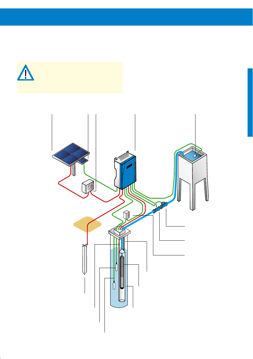
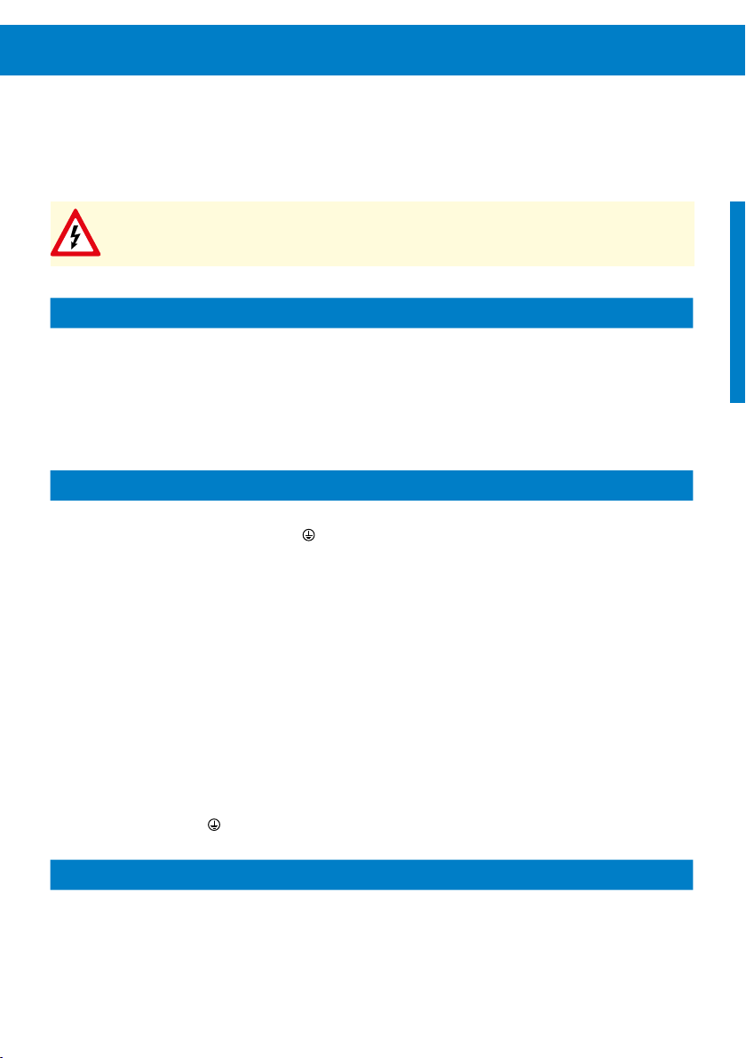
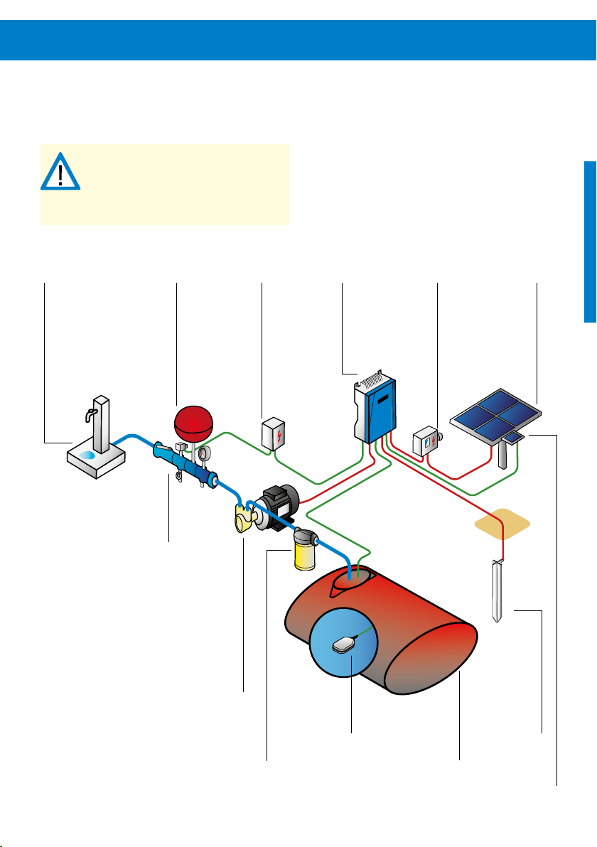
6.2 System Layout: Submersible Pumps
CAUTION - This graphic is an example
pump system layout diagram for ease of
understanding only. For system installation
and wiring read and follow the detailed
instructions given in this manual.
PV generator Sun Sensor
module
grounding rod
PV disconnect PS2 controller float switch
water meter
pressure sensor
surge protector
safety rope
submersible pump
splicing kit
well probe
level sensor
stilling tube
14 Pump System Sizing & Layout Diagrams
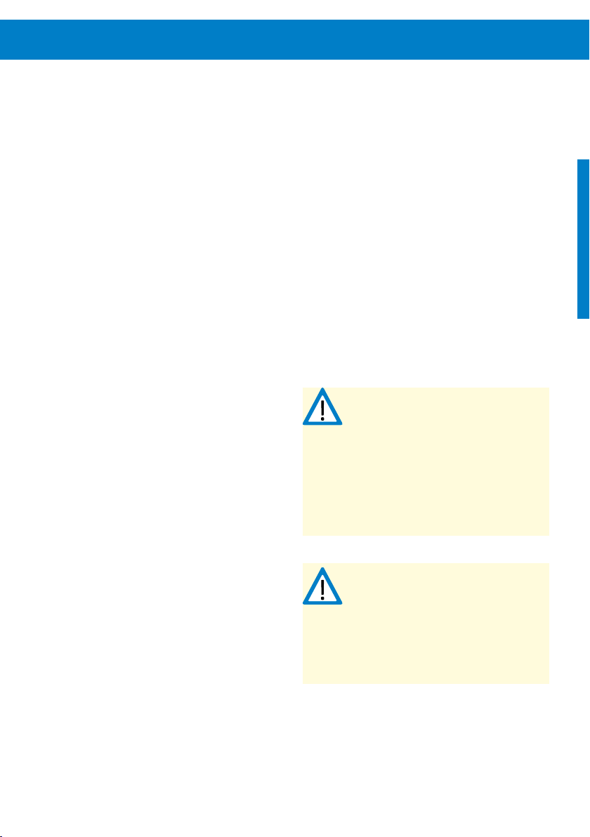
6.3 System Layout: Surface Pumps
CAUTION - This graphic is an example
pump system layout diagram for ease of
understanding only. For system installation
and wiring read and follow the detailed
instructions given in this manual.
PV generator Sun Sensor module PV disconnect PS2 controller float switch
surge protector
well probe
or float switch
nonreturn valve
filter cage
grounding rod
water meter
valve
filler
pressure sensor
surface pump
water sensor
strainer
gate valve
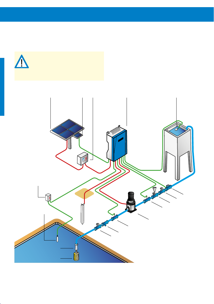
6.4 System Layout: Surface Boost Pumps
CAUTION - This graphic is an example
pump system layout diagram for ease of
understanding only. For system installation
and wiring read and follow the detailed
instructions given in this manual.
pressure tank
PS Boost installation kit
PV generatorPV disconnectPS2 controllersurge protectorwater tap
PS Boost pump
PS Boost inline filter
float switch
grounding rod
underground tank
Sun Sensor module
16 Controller Installation
7 Controller Installation
7.1 General
WARNING – All electrical connections must
be performed by qualified experts only.
WARNING – Do not dismantle the
controller while still connected to the
power supply! Before any installation,
maintenance or inspection activities wait
at least two minutes after the power
supply has been disconnected from the
controller!
CAUTION – To avoid multiple starts of the
pump in twilight conditions, the Sun
Sensor module must be connected and
configured for all PS2-1800 CS-F and all
PS2-4000 pump systems. Operating
without a Sun Sensor module can lead to
increased wear or damage to the pump.
Such damage is excluded from the
warranty.
CAUTION – Never let the pump run dry.
Dry running will damage the pump and
void the warranty. LORENTZ requires a dry
run protection for every pump system.
For more information on mandatory accessories and their
installation, please refer to “7.6.3 Pump Accessories Wiring”
on page 27 and “9 Pump Accessories Installation” on
page 57.
Treat the controller as industrial waste when processing the
discarded controller. It is possible that some components
could produce toxic and harmful gas.
A plug kit is available separately from the controller if plug
connectors shall be used.
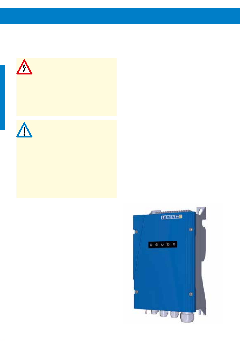
Figure 2: PS2 controller

DC Disconnect Switch
Electrical Conduit
Every solar pump system must be equipped with a properly
sized DC disconnect switch. The switch must be installed
between the PV generator and controller. It must meet the
following requirements:
minimum rating according to “Table 1: Minimum DC
disconnect rating” on page 17
continuous current rating according to maximum
current of the connected PV generator or higher
the switch must be rated for DC current, not AC
A PV disconnect switch matching all requirements above
can be purchased from LORENTZ.
CAUTION – The use of a properly sized
disconnect switch is an important safety
measure and obligatory for a professional
installation of a solar pump system.
Table 1: Minimum DC disconnect rating
Controller Min. DC disconnect switch rating
PS2-150 50V DC
PS2-200 100V DC
PS2-600 150V DC
Electrical conduit is recommended. We recommend the use
of an electrical conduit (pipe) to protect outdoor wiring
from the weather, from human activities and from damage
caused by animals. If you do not use a conduit, use a strong,
high-quality outdoor cable. Where cables enter the junction
box, install sealed strain-relief cable glands.
Wire sizes
For signal cables, the min. wire size should be 1.5 mm²
(16AWG). For power cables, the min. wire size should be 2.5
mm² (14AWG). Compare your wire sizes to the LORENTZ
COMPASS sizing reports. Cables should be shielded to meet
EMC the requirement.
For outdoor use, cables meeting the requirements of 60245
IEC 66 are recommended. For indoor use, the recommended
cable type is defined in 60245 IEC 57. The installer must
always consider the local situation, codes of practice and
regulations and use a cable that meets these requirements.
PS2-1800 200V DC
PS2-4000 375V DC

18 Controller Installation
7.2 Controller Elements
Power on/off switch – The power switch is used to
start or stop the system and as a reset switch. It does not
work as power disconnect switch.
Indicator Lights – The five LED lights on the front
indicate different operational situations. For a detailed
explanation refer to chapter “10 Operating the Pump”
on page 64.
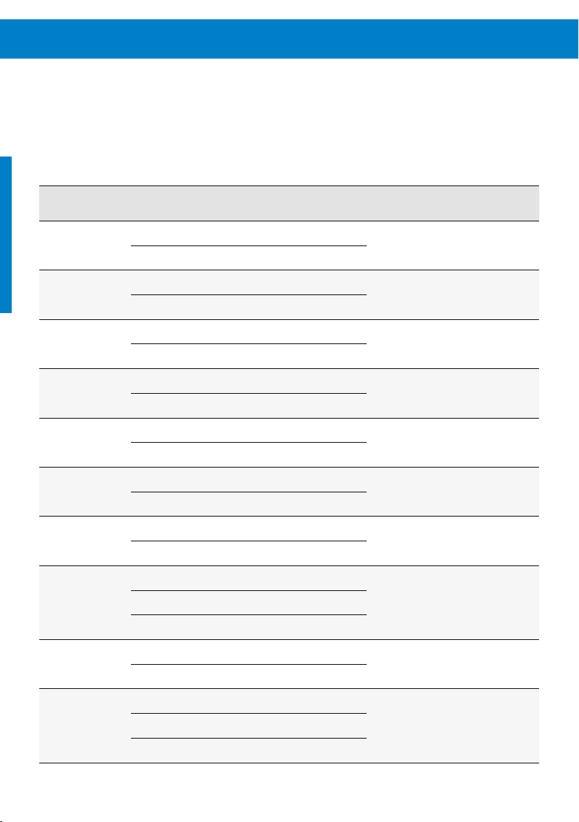
Table 2: Technical data of the PS2 controller
Model Pump motor:
PS2-150
Boost
PS2-150 0.3 ECDRIVE 150-C 50 17 22
rated power
[kW] [V] [V] [A]
0.3 ECDRIVE 150-Boost 50 17 22
Affiliated pump
motor
7.3 Technical Data of the Controller
Refer to “Table 2: Technical data of the PS2 controller” on
page 18 for an overview of the most important technical
specifications of the PS controller.
Max. DC input
voltage
Min. recommended
Vmp
Max.output
current
PS2-200 0.3 ECDRIVE 200-HR 100 34 11
ECDRIVE 600-HR
PS2-600 0.7
PS2-1800 1.7
PS2-4000 4.0
ECDRIVE 600-C
ECDRIVE 600-CS-F
ECDRIVE 1800-HR
ECDRIVE 1800-C
ECDRIVE 1800-CS-F
ECDRIVE 4000-HR
ECDRIVE 4000-C
ECDRIVE 4000-CS-F
150 68 13
200 102 14
375 238 14

7.4 Controller Placement
7.5 Mounting, Space and Ventilation Requirements
The controller must be protected from water, moisture and
animals, so keep the controller box sealed. Place the controller in a dry and sufficiently ventilated environment.
Place the controller close to the solar array, not the pump,
to reduce the risk of lightning damage. The controllers’ input
circuitry is more sensitive to surges than its output. Therefore it is safest to minimize the length of the input wiring.
Electronic devices are most reliable when they are protected
from heat. Mount the controller where it is shaded from
the midday sun. An ideal location is directly under the PV
generator. If no shade is available, cut a piece of sheet metal
and bolt it behind the top of the controller. Bend it over the
controller to provide shade. This is especially important in
extremely hot locations. Extreme heat may trigger a thermal
function in the controller causing it to reduce the power
consumption or turn it off. The controller housing can reach
high temperatures when operating at high ambient temperatures. This is normal and will not reduce the expected
lifetime of the controller or its components.
PS2 controllers can be mounted side by side.
For grounding of the front cover the cover screws must be
tightend to a minimum torque of 2Nm.
All PS2 controllers have a fan-less design; they are cooled
by air convection. It is strictly advised not to install the controller in an additional enclosure. If an additional enclosure
is necessary a sufficient vertical airflow (from bottom to top)
has to be ensured to allow sufficient cooling.
PS2 controllers have a keyhole mounting system to
simplify mounting on appropriate surfaces. For mounting
on poles and similar structures the PS2 is compatible with
the LORENTZ PM accessory brackets for a maximum of
convenience.
When mounting the PS2 controller with the LORENTZ PM
accessory brackets tighten the screws diagonally and evenly.
CAUTION – do not over tighten the
mounting screws on the PS2 housing when
using the PM accessory brackets to avoid
damage to the PS2 controller housing.
CAUTION – When using PM accessory
brackets, for high performance systems
and/or with high ambient temperatures a
backplate must be installed between the
controller and the PM accessory brackets
to preserve the funnel effect of the
cooling fins. Operating without a
backplate can lead to insufficient cooling
which will result in reduced performance.
For controller dimensions, cf. “Table 3: PS2 Controller dimensions for installation” on page 20.

20 Controller Installation
Figure 3: PS2 Controller dimensions for installation
W3
H1
H2
H3
D1W2
W1
Table 3: PS2 Controller dimensions for installation
Dimension in mm [in]
Weight in kg [lbs]W1 W2 W3 H1 H2 H3 D1
207 170 164 352 333 300 124 4.5
[8.15] [6.69] [6.46] [13.86] [13.11] [11.81] [4.88] [9.9]

7.6 Wiring the Controller
WARNING – All electrical connections must
be performed by qualified experts only!
Unqualified handling might lead to shock,
burns, or death.
WARNING – Beware of high voltage.
Never work on a system connected to
power or within two minutes after
disconnection to avoid electric shock
hazard.
Before starting to work on the electrical system make sure
that all components are disconnected from the power
source. Do not work on any components when power is
connected or within two minutes after disconnection. The
controller needs time to discharge.
Switch the system on only when all work is completed.
CAUTION – The controller should only be
connected to power after correct wiring or
the controller might get damaged.
CAUTION – Do not install disconnect
switches in the power wires between the
motor and pump controller. Connecting the
motor wires to a switched-on controller
may cause irreparable damage. Such
damage is excluded from the warranty.
CAUTION – Solar-direct systems only – Do
not connect any electrical load to the PV
generator other than the LORENTZ pump
controller. Connection of a battery charger,
active solar tracker controller, electric
fence charger, or other load simultaneously with LORENTZ PS2 systems may
interfere with the controller and prevent
proper operation.
CAUTION – Measure the voltage before
connecting power to the controller.
Voltage (open circuit) must not exceed the
max. DC input (refer to “Table 2: Technical
data of the PS2 controller” on page 18).

22 Controller Installation
7.6.1 Terminal Descriptions
Open the housing by loosening the four screws on the front
cover. After removing the cover the terminal can be accessed
easily.
For “Power in” and “Motor” open the clamp, insert the
wires and lock the clamps in place. Use caution and keep
hold of the clamp handles as the terminals contain strong
springs. Refer to “Figure 6: “Power in” and “Motor” terminal” on page 23. The length of wire stripping for these
terminals is 12 - 13 mm (0.5 in).
Figure 4: View of open PS2 controller
Solar in +–
For terminals 1 to 17 open the terminal by pushing back
the clamp handle with a screw driver, insert the wire, then
release the handle to lock the wire in place. Refer to “Figure
7: Terminals 1 – 17” on page 23. The length of wire
stripping for these terminals is 5 - 6 mm (0.2 in).
Terminals 1 - 17
Ground
Sensor cable glands
Pump L1 L2 L3
Motor cable glandSolar in cable glands
Outside grounding bolt

Terminal Description PS2
Figure 6: “Power in” and “Motor” terminal Figure 7: Terminals 1 – 17
Figure 5: Terminal PS2
Open
Close
Insert wire
use a flat screwdriver
to push back
Close
Open
Insert wire
1 2 3 4 5 6 7 8 9 10 11 12 13 14 15 16 17
com com com +24V +24V +24V com + –
Well
probe
Remote
switch
Water
meter
Analog 1
4-20mA
Analog 2
4-20mA
Out
Water
sensor
Sun
Sensor
24 Controller Installation
Table 4: Terminal explanation
Socket Terminal Connection Function
Power in
Well probe
(Source low switch)
Remote switch
Water meter
Analog input 1
Analog input 2
Out
Water sensor
+ connect to positive terminal of PV module
– connect to negative terminal of PV module
1 connect to NC
2 connect to COM
3 connect to NC
4 connect to COM
5 connect to Imp
6 connect to COM
7 connect to positive (+)
8 connect to signal
9 connect to positive (+)
10 connect to signal
11
12
13 connect to positive (+)
14 connect to signal
15 connect to COM
Connect the PV array to the controller.
Connect well probe or float switch to
protect the pump system from running
dry.
Connect a float switch, pressure switch
or any other suitable remote switch.
(Factory setting: jumper installed)
Connect a water meter with pulse
output. l/imp must be configured with
PumpScanner.
Connect a 4−20mA signal sensor;
supply voltage +24V load; must be
configured with PumpScanner.
Connect a 4−20mA signal sensor;
supply voltage +24V load; must be
configured with PumpScanner.
Potential-free signal output to control
third party devices; must be configured
with PumpScanner.
Connect a water detection sensor for
surface pumps. (Factory setting: jumper
installed between 14 and 15)
Sun Sensor
Output to motor
16 connect to positive (+)
17 connect to negative (–)
L1 connect to the L1 phase of the motor
L2 connect to the L2 phase of the motor
L3 connect to the L3 phase of the motor
Connect the LORENTZ SunSensor for
irradiation based pump control; must be
configured with PumpScanner.
Connect the power wires of the
LORENTZ pump motor.
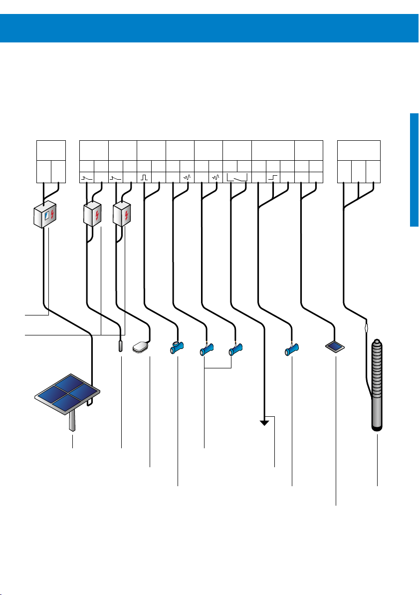
Terminal Wiring Example
Figure 8: Terminal wiring example
SOLAR
IN
+ –
PV disconnect
Surge protector
Well
Remote
probe
1 2 3 4 5 6 7 8 9 10 11 12 13 14 15 16 17
com com com +24V +24V +24V com + –
switch
Water
meter
Analog 1
4-20mA
Analog 2
4-20mA
Out
Water
sensor
Sun
Sensor
Pump
L1 L2 L3
PV generator
Well probe
Remote switch
Analog sensors
Out
Water sensorWater meter
Pump
Sun Sensor

26 Controller Installation
7.6.2 Pump Wiring
The motor cables of the pump have a marking to allow
correct wiring. Connect the wires using this sequence:
1: Motor cable L1
2: Motor cable L2
3: Motor cable L3
: Ground connection
If necessary, interchange any two phases to reverse direction. Refer to chapter “8 Pump Installation” on page 32
for detailed pump installation instructions.
7.6.3 Pump Accessories Wiring
Terminals 1 and 2
To protect the pump from being damaged by dry running
connect a suitable source low protection switch to terminal
1 and 2. Every pump system must be equipped with dry run
protection. If dry run protection is not needed, add a jumper
wire between these two terminals.
CAUTION - Never let the pump run dry.
Dry running will damage the pump and
void the warranty. LORENTZ requires a dry
run protection for every pump system.
Terminals 3 and 4
Connect any kind of external switch for remote control of
the controller. To run the pump the switch must be closed
(NC). If no switch is used the terminals No. 3 and 4 have to
be connected with a jumper cable (factory setting).
Terminals 5 and 6
Install a water meter in the pipeline and connect it to
terminal 5 and 6. The output of the water meter must be
an impulse signal. The time between two impulses must not
exceed 5 minutes. The DataModule can handle up to 10
impulse per second. Select a water meter appropriate for the
expected flow. The flow can be viewed with the LORENTZ
PumpScanner software.
Terminals 7 and 8 / 9 and 10
Any suitable sensor for 24VDC supply voltage, current
(signal) range of 4–20mA and load impedance of 100Ω
can be connected, e.g. LORENTZ pressure sensor, LORENTZ
liquid level sensor. The sensor must then be configured in
PumpScanner.
Terminals 11 and 12
This is a potential-free signal output contact that can be
configured in PumpScanner to control third party devices. It
is rated for: 24VAC, 24VDC, 1A.
Terminals 13, 14 and 15
Connect a water sensor to detect the presence of water, this
is usually installed on the suction side of surface pumps for
dry run protection. If no water sensor is connected a jumper
wire must be installed between terminals 14 and 15 (factory
setting). The maximum allowed current for sensor supply is
20mA.
Terminals 16 and 17
Connect a LORENTZ 1.5Wp Sun Sensor module module.
This PV module is used to measure the solar irradiation and
allows you to set irradiation dependent START / STOP values
for the pump. These settings can only be done via LORENTZ
PumpScanner.
CAUTION – Only connect a suitable sensor
to terminals 7 and 8 / 9 and 10 / 13, 14 and
15. Never create a short circuit. Observe
the polarity of the pressure sensor.
28 Controller Installation
7.6.4 Input Wiring for Solar-direct Systems
WARNING – Beware of high voltage!
Electric shock hazard! Hazardous
electricity may be present and can shock,
burn, or cause death! Authorised, qualified
personnel only!
The PV generator can produce hazardous voltage even under low light exposure. To prevent shock hazard while wiring
the array, leave one or more wires disconnected or cover the
solar array with opaque material.
Table 5: Max. voltage input
Controller
PS2-150 50VDC
PS2-200 100VDC
PS2-600 150VDC
PS2-1800 200VDC
PS2-4000 375VDC
Max. DC input voltage
CAUTION – An input voltage higher than
specified in “Table 5: Max. voltage input”
on page 28 will damage the controller
and void the warranty. Damage may occur
if the solar generator array is wired
incorrectly. Measure the voltage and
confirm the polarity before connecting the
power to the controller.
Connect the positive terminal of the PV modules to + and
the negative terminal of the PV modules to –. Connect the
protective ground wire to an appropriate ground system.
Refer to “7.6.1 Terminal Descriptions” on page 22 for
terminal descriptions and to “7.6.6 Grounding” on page
30 for grounding instructions.

7.6.5 Input Wiring for Battery-based Systems
CAUTION – The PS2-4000 pump system can
not be operated from batteries.
The battery mode for PS2-150 to PS2-1800 controllers
must be activated in PumpScanner. This will deactivate
the MPP-Tracking function and activate the Low Voltage
Disconnect (LVD).
Connect the PS2 controller directly to the battery and NOT
to the load terminals of the charger as the terminals may
not be rated for the starting load current of the pump. The
PS2 controller has a low voltage disconnect function to
protect the battery from being deeply discharged.
Some charge controllers monitor the capacity of the battery
and regulate the charging accordingly. This method does not
work when the PS2 controller is connected to the battery. In
order to provide correct charging the charger should be set
to voltage orientated regulation. This may require a jumper
to be set in the charger. Check the manuals of the charger
manufacturer.
Short circuit protection: Install a fuse or circuit breaker
near the power source. Use a 30 A circuit breaker or a time
delay (slow blow) fuse.
Low-voltage disconnect function: Lead-acid batteries
can be permanently damaged by over-discharge when the
voltage falls below a critical point. To prevent this, the PS2
battery system controller will turn off at low voltage for at
least 20 minutes, and turn back on only after the battery has
recovered significantly.
Battery high run mode: If high run mode is activated in
PumpScanner, the low voltage disconnect points for 12V
batteries are changed to OFF at 12.3VDC, ON at 13VDC.
Set points for low voltage disconnect
Controller Voltage OFF ON
PS2-150
PS2-200
PS2-600 48VDC 44VDC 48VDC
PS2-1800 96VDC 88VDC 96VDC
12VDC 11VDC 12VDC
24VDC 22VDC 24VDC
24VDC 22VDC 24VDC
48VDC 44VDC 48VDC

30 Controller Installation
7.6.6 Grounding
Before starting to work on the electrical system make sure
that all components are disconnected from the power
source. Only switch on the system when you have finished
all work.
Grounding is mandatory to protect the users from potentially fatal electric shocks. It also protects against electric charging or a short circuit inside the device. This is accomplished
through clamping, bolting or other mechanical means to
provide an effective grounding path to the earth to ensure
safe operation at all time.
The grounding is also important to the system for lightning
protection. In general it is meant for indirect lightning strikes
and induced electrical potentials during operation of the
pump system.
Before installation, contact the local code authorities to
determine the necessary grounding requirements.
Insufficient ground source: Where there is an
inadequate ground source you can use a grounding rod.
A grounding profile rod should be located not more than
4 – 5m (13 – 16 ft) from the controller. The cable must not
carry any mechanical loads. The rod must be completely buried in the ground (2.5 m/8 ft below ground level). You must
refer to local standards and requirements. The grounding
cable should be a copper cable with a cross section of not
less than 16 mm2 (AWG 6).
A protective earth connection must be linked to the
controllers earth connector which is located below the pcb
and marked with the protective earthing symbol . The
protective earth wire of the motor must also be connected
to the controllers earth connector.
The protective earth connection can also be linked to the
grounding bolt on the outside of the controller near the
cable glands.
All metallic support structures and electrical enclosures must
be grounded.
For grounding of the front cover the cover screws must be
tightend to a minimum torque of 2Nm.
For grounding of the PV generator, follow manufacturer
instructions.

7.7 PS2 pool pump systems
7.8 PS2 boost pump systems
NOTE – The following chapter is relevant
for PS2 controllers operating pool pumps
only.
WARNING – The use of pumps for
swimming pools and the restricted area
around them is only permitted if pumps
are installed in accordance with DIN/VDE
0100 part 702 or other local standards.
Please consult your licensed electrician!
WARNING – A cord and plug connected
unit shall be provided with a permanently
attached flexible cord of a water-resistant
type, e.g. SEW, SEOW, SJW, SJOW, SJEW,
SJEOW, SJTW, SJTOW, SOW, STW, or STOW.
When the pump is connected by cable, use
extra-hard type (toughened) cable for
connections.
WARNING – When the motor is installed
within 1.5 m/5 ft of the inside walls of a
swimming pool, spa, or hot tub, a
solid-copper bonding-conductor not
smaller than 8.4 mm²/ AWG 8 must be
connected from the accessible wire
connector on the motor to all metal parts
of the swimming pool, spa, or hot tub
structure and to all electrical equipment,
metal conduit, and metal piping within 1.5
m/5 ft of the inside walls of the swimming
pool, spa, or hot tub.
NOTE – The following chapter is relevant
for PS2-150 controllers operating boost
pumps only.
Before start-up of the boost pump system manually set the
system to the correct boost pump end with PumpScanner.
Please refer to the PumpScanner manual on partnerNET.
CAUTION – starting the boost pump
without selecting the correct boost pump
end will damage the pump. Such damage
is excluded from the warranty.
Before start-up of the pool pump system manually configure
the controller to the correct pool pump end with PumpScanner. Please refer to the PumpScanner manual on partnerNET.

32 Pump Installation
8 Pump Installation
8.1 General Instructions
WARNING – All electrical connections
must be performed by qualified experts
only.
WARNING – Before starting any work on
the pump/motor, make sure that the
electricity supply has been switched off
and that it cannot be accidentally
switched on!
CAUTION – Before you start the assembly,
make sure that all parts were delivered
and have not been damaged during
transport.
8.1.1 Pipe Sizing
LORENTZ pump systems are extremely efficient. It is important to keep this efficiency throughout the entire system.
A main reason for loss of efficiency is pipe pressure losses.
Make sure that you have included the pipe pressure losses
during the sizing process of your system.
Consider a smart pipeline design from the beginning.
CAUTION – Consult COMPASS or a pipe
pressure sizing chart to determine the
correct size. Oversize the pipe line to
reduce the pressure drop.
CAUTION – The length of the inlet and of
the outlet pipeline must be considered for
the calculation of the pressure losses
CAUTION – Only run the pump when it is
completely prefilled with water (surface
pumps), submersible pumps must be
completely submerged. This means there
must be no air in the pipes.
CAUTION – For surface pumps, air locks
must be avoided at the inlet pipe line.
Avoid sharp 90° elbows and sharp pipe
size adaptors.

8.2 Pump System Type
8.1.2 Cable Splicing
To connect the motor cable with a cable extension you
should connect the cable ends with a splicing kit.
It is very important that the cable joints are fully sealed otherwise moisture could cause a short circuit. This will damage
the pump system.
For more information about connecting cable ends with a
splicing kit see the “submersible cable splicing” manual in
the package of the splicing kit.
CAUTION – Cable splice failures are a
common source of errors. Check the splice
for proper connections.
CAUTION – Bad cable splicing can damage
the controller and/or the pump. Such
damage is excluded from the warranty.
Depending on your pump system, please refer to the correct
chapter for installation instructions:
Pump type Chapter
Submersible 8.3
Surface CS-F 8.4
Surface Boost 8.3
To determine the type of system you have, please refer to
chapter “3.4 Naming” on page 8.

34 Pump Installation
8.3 Submersible Pumps
For submersible pumps only: The ECDrives are water
lubricated and therefore prefilled with water. If the motor is
stored for more than three months, the water will have been
pressed out; the rotor must be turned by hand before use to
ensure that the rotor is not stuck.
8.3.1 Wiring the Pump
CAUTION - No disconnect switches must
be installed between the motor and the
pump controller. Connecting the motor
wire to the switched-on controller might
irreparably damage it. Such damage is
excluded from the warranty.
CAUTION – If the pump wires are in the
wrong order, the motor will run in reverse
and the pump will not function correctly.
Damage may result. Check the direction
before installing the pump. The proper
direction is counter-clockwise when
viewed from above.
CAUTION – Never let the pump run dry.
Dry running will damage the pump and
void the warranty. LORENTZ requires dry
run protection for every submersible
pump system.
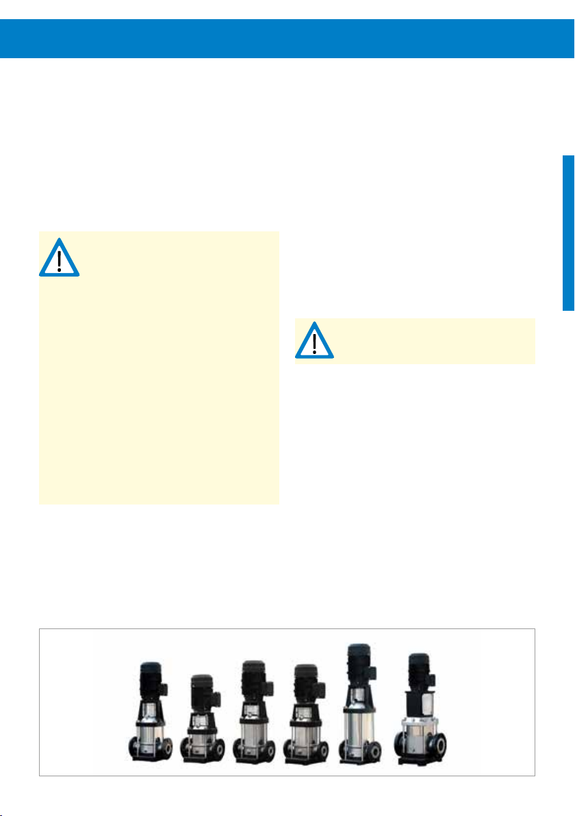
Figure 9: Exemplary LORENTZ submersible pumps
The motor cables of the pump have a marking to allow
correct wiring. Connect the wires using this sequence:
1: Motor cable L1
2: Motor cable L2
3: Motor cable L3
: Ground connector
The submersible pump must be submerged in water before
checking the correct rotational direction. The correct rotation
direction for submersible pumps is counter-clockwise,
viewed from the top. It is also labelled with an arrow on the
pump end.
The testing process for rotational direction depends on
the pump type. Please refer to the next page for detailed
instructions on testing helical rotor (HR) and centrifugal
submersible pumps. To determine which type of pump you
have, please refer to “3.4 Naming” on page 8.

HR Pumps:
Centrifugal Pumps:
The HR pumps are positive displacement pumps and
hence will only deliver flow rate when running with correct
rotation direction. They will be damaged when running in
reverse.
A new pump “out-of-the-box” is shipped from the factory
with a temporary lubrication film on the rotor which allows
a test run of max. 5 seconds in total without submerging
the pump. Once the pump came in contact with water the
temporary lubrication is gone and the pump must not be
operated without being completely submerged! Submerging
only the inlet is not sufficient and will result in damage to
the pump end.
Check the rotational direction as follows:
(1) Connect the pump to the controller and power supply.
(2) Observe the information regarding HR pump testing
above and follow them strictly!
(3) Start the pump and check the rotation direction by
observing the motor shaft at the pump inlet.
(4) Compare to the indicated rotation direction on the
pump end.
(5) In case the direction is wrong, switch off immediately
and change two of the three phase leads.
(6) Start the pump again and check the rotation direction.
Do not exceed 5 seconds of combined testing time.
Check the rotational direction as follows:
(1) Connect the pump to the controller and power supply.
(2) Start the pump and check the delivered flow rate.
(3) Stop the pump, disconnect the power supply and
change two of the three phase leads.
(4) Start the pump again and check the delivered flow.
(5) Stop the pump, disconnect the power supply and com-
pare the flow rates from point 2 and 4. The wiring with
the better flow rate has the right rotational direction.
(7) The pump will only deliver water flow when running
with correct rotation direction.

36 Pump Installation
8.3.2 Installation and Handling
To lower the pumps into the borehole, a crane or hoist is
recommended, depending on the size and weight of your
pump system.
All parts have to be strong enough to withstand the weight
of the pump, the motor, the motor cable and the pipe
system.
It is also helpful to lower a pump dummy into the borehole
before you lower the pump to make sure that the hole
is completely free and the pump can slide into the hole
without obstructions.
WARNING – Never stand under suspended
loads.
WARNING – Always take suitable security
precautions (e.g. a strong safety rope) to
safeguard the pump against slipping into
the well during installation!
CAUTION – Be careful not to bend the
pump, take particular care with centrifugal (C) pumps with a high number of
stages. Make sure that the pump never
stands on the motor cable, that the cable
does not get jammed or damaged by
sharp ledges or that the cable is not
pulled or jerked where it enters the motor.
Round off the edges of a flange to prevent damage to the
cable. Do not fix the cable tightly. Leave space for the pipes
to expand. The cable needs to get fixed every 3 m.
NOTE – Measuring and noting down the
distances between the fixing will help to
lower the pump to the right depth.
Figure 10: Fixing of the motor cable at a joint and a strait
pipe
50
tape
During the process of lowering the pump into the well the
motor cable has to be fixed properly to the pipe, see “Figure
10: Fixing of the motor cable at a joint and a strait pipe” on
page 36. Where a plastic pipe is used, the longitudinal
stretch of the pipe under load has to be considered by
leaving a sufficient gap between the pipe and the cable! The
cable should be fixed with water-resistant tape. It is a good
installation practice to form a loop with the motor cable
near the pump and repeat it about every 40 m / 130 ft along
the riser pipe. This will keep any tensile forces away from the
motor cable.
To extend the motor cable pay attention to chapter “8.1.2
Cable Splicing” on page 33.
77
5050
3 m
77

8.3.3 Installation Depth
8.3.4 Removal
Make sure that the pump unit is suspended properly and is
not in contact with sand and mud from the well bottom. It
is recommended to install the pump above the filter zone
(= water entry zone) of the well to keep the sand content in
the water low and ensure proper cooling of the motor.
CAUTION – The pump must be submerged
completely. Never let the pump run dry.
Dry running will damage the pump and
void the warranty. LORENTZ requires a dry
run protection for every pump system.
CAUTION – If the pump does not hang
above the filter zone a flow sleeve is
necessary.
If you have to remove the pump system it is the same principle as the installation in reverse order. When removing the
pump the pipes will be full of water and will be heavier.
CAUTION – When the pump system is
lifted out of the well the pipes are full of
water. This causes additional weight.
In the table below you can see the additional weight of the
water per meter pipe length.
Table 6: Additional weight per meter pipe length
Pipe diameter Additional weight
[in] [kg/m] [lb/ft]
2 2.0 14.5
2.5 3.2 23.1
3 4.6 33.3
4 8.2 59.3
5 12.7 91.9
6 18.4 133.1

38 Pump Installation
8.3.5 Additional Features
8.3.5.1 Safety Rope
We recommend the use of a safety rope as a loss insurance.
If the pipe breaks because of start-up torques of the motor,
too much weight, pipe corrosion or wrong installation a
safety rope can prevent the total loss of the pump system
and damage to the well.
Choose a safety rope that can handle the weight of the
whole installation and the water inside the pipes. The rope
material must be water-resistant. Near the well head the
rope needs to be UV-resistant or protected from sunlight.
CAUTION - Do not use a nylon rope. Nylon
is known to absorb water over time which
will weaken the rope.
8.3.5.2 Plastic Pipes
When the pipes are strong enough the use of plastic pipes is
possible. If you are not sure about the strength of your pipes
contact the pipe manufacturer.
CAUTION - The pipes must be strong
enough to hold the whole weight of the
pump, the motor, the pipe system and the
water in the pipes. It must also withstand
the water pressure generated by the total
dynamic head.
8.3.5.3 Stilling Tube
For the maximum recommended sand content, before any
significant detrimental effects occur, check chapter “4
Operating Conditions” on page 9.
A higher content will cause excessive wear within the pump
and reduce the pump’s life span considerably. Any pump
that is blocked by sand will not be covered by warranty.
To reduce the amount of particles entering the pump, a
stilling tube can be installed, see “Figure 11: Stilling tube”.
Figure 11: Stilling tube
CAUTION - When using plastic pipes you
should always use a safety rope.
8.4 CS-F Surface Pumps
8.4.1 Placement and Foundation
Rain and weather protection – The pump is equipped
with IPX4-type motor protection. If it is installed outside, the
pump must be protected from rain and direct sunlight. This
will increase the durability of your pump.
CAUTION – CS-F pumps must not be
submerged in water or subjected to rain
or dripping water.
CAUTION – If the pump is installed in a
humid area, effective ventilation and
aeration must be provided in order to
prevent condensation.
CAUTION – When installing in very small
installation spaces the natural cooling
may be insufficient. Carefully consider the
ventilation in order not to exceed the
maximum ambient temperature.
CAUTION – The pump might heat up in
operation. The pump must not be installed
on combustible surfaces. Strong
incombustible surfaces should be used,
e.g. concrete or stone surfaces.
Foundation – An arrow on the pump base shows the
direction of the flow of the fluid through the pump. It is
recommended to install the pump on a concrete foundation.
The foundation must be level and should have min. approx.
1.5 times the weight of the pump to absorb vibration, shock
and strain.
Connecting the pump to the foundation – Fastening
the pump to the foundation should be done exclusively by
means of properly sized bolts or threads (dowels) in order to
avoid any movement of the pump unit.
CAUTION – The pump must be mounted
vertically.
Space – During installation, make sure that there is enough
space available to permit subsequent disassembly of the
motor unit. It is recommended to have at least 1m of free
space above the pump.
Figure 12: Exemplary LORENTZ surface pumps

40 Pump Installation
8.4.2 Pump Motor Wiring
WARNING – The wiring has to be done by
qualified service personnel only.
WARNING – Beware of high voltage!
Electric shock hazard!
The ECDRIVE must be connected to the terminals L1, L2, L3
and the ground connector. The ECDRIVE requires four-conductor (four-wire) cable between the controller and the
motor. The three wires L1, L2 and L3 carry power. The fourth
wire carries ground. Connect the ground wire to the ground
connection below the pcb in the controller. Grounding helps
to prevent shock hazard if there is a fault in the motor.
The correct order of the three motor phases is marked on
the motor cables itself. Prior to splicing the order of the
motor phases should be transferred to the cable. This will
simplify the wiring.
CAUTION – No disconnect switches must
be installed in power wires between
motor and pump controller. Connecting
the motor wires to a switched-on
controller may cause irreparable damage
which is excluded from the warranty.
CAUTION – If the pump wires are in the
wrong order, the motor will run in reverse
and may damage the pump. Never let the
pump run dry, not even for the purpose of
checking the direction of rotation.
Check the correct rotation direction after the pump is filled
with water, see chapter “8.4.5.2 Rotary Direction” on page
44.
8.4.3 Installation and Handling
Handling – When lifting the pump use the eyebolts at the
motor housing. If that is not possible lift the pump at the
motor flange by using a holder or straps.
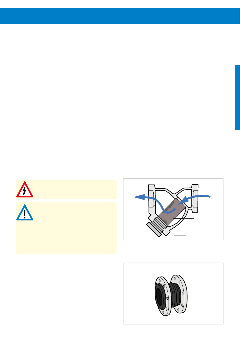
Strainer – If pipelines are welded together metal pieces
might be present in the pipeline. Before pump installation,
the inlet pipeline must be carefully cleaned. It is recommended to install a strainer about 1 m / 3 ft in front of the
pump inlet to avoid pump damage due to any kind of impurities (cp. “Figure 13: Strainer”). The pressure drop of the
strainer must be considered in the suction lift calculation.
Pipe system – We advise that pipe expansion joints are
used close to the pump on both inlet and outlet to reduce
noise and vibration (cp. “Figure 14: Pipe expansion joints”).
It is recommended that you install a gate valve in the
suction and discharge pipeline close to the pump to avoid
draining of the pipe while cleaning (e.g. filters), repairing,
servicing or replacing the pump system.
WARNING – Inlet and outlet pipes must be
mounted to the pump housing free of
tension.
CAUTION – Make sure that the suction
pipe is sealed with no leaks, otherwise the
pump will not prime or will prime
insufficiently.
CAUTION – The pumps are shipped with
plastic covers on the pump inlet and
outlet. Remove them before connecting
the pipes to the pump.
Check valve – A check valve at the inlet pipe is needed
to assure that the pump and its suction pipeline remains
completely water filled during the time the pump is switched
OFF. Always install a check valve with one inch (1”) larger
diameter than the suction pipe in order to avoid too much
suction pressure drop. For example if the suction pipe size is
3”, then a 4” check valve should be installed.
Figure 13: Strainer
filtered
flow
particle accumulation
Figure 14: Pipe expansion joints
unfiltered
flow
filter element

42 Pump Installation
8.4.4 Suction Head
The maximum suction head is limited by the local air pressure, the water temperature of the medium, the pipe losses
and the NPSH value of the pump.
CAUTION – If the suction pressure in the
pump is lower than the vapor pressure of
the fluid, cavitation will occur. Cavitation
creates noise and will damage the pump.
Damage due to cavitation is not subject to
warranty. To avoid cavitation, the pressure
of the fluid must be maintained above its
vapor pressure at all points as it passes
through the pump.
The maximum suction head (H) must be calculated in
advance. The LORENTZ pump sizing software COMPASS can
be used for NPSH calculation.

8.4.5 Initial Start-up
CAUTION – Never start the pump if it is
not filled with water and has not been
vented. The pump and suction pipe must
be fully filled with clean water otherwise
the pump will be damaged
8.4.5.1 Filling Pump with Water
The pump and the whole suction pipe must be fully filled
with clean water.
If the water source level is higher than the pump
inlet:
1. Close the gate valve in the outlet pipe and loosen the
air vent screw.
2. Open the gate valve in the suction pipe slowly.
3. Tighten the air vent screw when water streams out
continuously.
If the water source level is below the pump inlet:
Suction pipeline and pump must be filled with water
manually.
1. Close the gate valve in the outlet pipe and open the
gate valve in the suction pipeline.
2. Loosen the air vent screw and fill clean water into the
pump through the filler pipe.
3. Fasten the air vent screw after the pump and the
suction pipeline are completely filled with water.
WARNING – Do not start the pump until it
has been filled completely with water.
WARNING – Make sure that the installed
shutoff valves in the suction and pressure lines are completely open during
operation, the pump must never run with
shutoff valves closed!
Figure 15: Vent and drain holes
CAUTION – Installing a suitable filler pipe
is highly recommended for proper priming
of the pump system. A pump system which
is not primed completely will likely get
damaged when it is switched on.
CAUTION – A nonreturn valve must be
installed at the start of the inlet pipeline
otherwise it is impossible to prime the
pump successfully.
Air vent hole
Water drain hole

44 Pump Installation
8.4.5.2 Rotary Direction
CAUTION – Never let the pump run dry,
not even for the purpose of checking the
direction of rotation! Dry running will
damage the pump and void the warranty.
Switch on the power supply and look at the rotary direction
by looking at the motor fan. An arrow on the pump unit
indicates the correct direction of the rotation.
Viewed from the top, the pump turns counterclockwise.
8.4.5.3 Final Check-up
Check whether the foundation bolts are fastened, the pump
and suction pipes are completely filled with water, the
voltage of the power supply is correct and that the pump
turns correctly. Make sure all pipelines are connected tightly
and can supply water normally. Make sure there is no closed
valve or other obstruction in the water line.

8.5 Pool Surface Pumps
8.5.1 Placement and Foundation
CAUTION – This pump is for use with
permanently-installed pools. Do not use
with storable/temporary pools.
CAUTION – The drain hole/pipe on the
bottom between pump housing and motor
must never be clogged or sealed. Blocking
the drain hole will result in an internal
build-up of water which will damage the
motor! Ensure that any drainage cannot
cause consequential damage! If necessary
provide a suitable drip pan.
CAUTION – If the pump is installed in a
humid area, effective ventilation and
aeration must be provided, in order to
prevent condensation.
CAUTION – The pump must be mounted in
horizontal position.
WARNING – The pump might heat up in
operation. The pump must not be installed
on combustible surfaces. Strong
incombustible surfaces should be used,
e.g. cement or stone surfaces.
Rain and weather protection – The pump is equipped
with IPX4-type motor protection. If it is installed outside, the
pump must be protected from rain and direct sunlight. This
will increase the durability of your pump.
Foundation – Installing the pump on a concrete foundation is recommended. The foundation must be completely
even and level. Its purpose is to absorb vibration and strain
in addition to preventing stress on pipe flanges.
Connecting the pump to the foundation – Fastening
the pump to the foundation should be done exclusively by
means of M8 bolts or threads (dowels) in order to avoid any
movement of the pump unit.
Figure 16: Pool Pump

46 Pump Installation
8.5.2 Pipe Sizing
Operating noise – Make sure, by applying appropriate
measures, that the local environment will not be impaired by
pump operating noise.
Table 7: Operating noise
Pump system Max. noise level
PS2-600 CS-17-1 65db
PS2-1800 CS-37-1 68db
Space – During installation, make sure that there is enough
space available to permit subsequent disassembly of the
motor unit in the direction of the motor fan (minimum 120
mm / 4.7”) and of the strainer basket above (minimum 140
mm / 5.5”).
When installing in very small spaces the natural cooling may
be insufficient and additional ventilation may be required.
Carefully consider the ventilation in order not to exceed the
maximum ambient temperature.
LORENTZ pump systems are extremely efficient. It is important to keep this efficiency throughout the entire system.
A main reason for loss of efficiency is pipe pressure losses.
Make sure that you have allowed for pipe pressure losses
during the sizing process of your system.
CAUTION – Consult COMPASS or a pipe
pressure sizing chart to determine the
correct pipe size. Oversize the pipe line to
reduce the pressure drop.
CAUTION – The length of the inlet and of
the outlet pipeline must be taken into
consideration when calculating pressure
losses.
CAUTION – Air locks must be avoided at
the inlet pipeline. Avoid sharp 90° elbows
and sharp pipe size adaptors.
Figure 17: Prevent air locks in pipes Figure 18: Avoid 90° elbows and size adaptors

8.5.3 Installation and Handling
CAUTION – The pump unit may be
installed at either a maximum of
3 m / 9’10” below (gravity feed) or above
(suction mode) the water level.
The suction lift may be significantly reduced by flow resistance in the suction line (if the pipes are very long and/or
insufficiently dimensioned). The suction/inlet pipe should be
as short as possible.
NOTE – Inlet and outlet of PS surface
pumps for pools are metric sized. The
pumps are supplied with adaptors which
are compatible with local market
requirements.
When ordering pumps for US/imperial (inch) markets adaptors are provided to connect standard NPS (inch) pipes.
When ordering pumps for metric markets adaptors are provided to allow connection of the next sized up metric pipe.
The table below shows the outer pipeline dimensions for the
pump inlet and outlet pipe using the supplied adaptors.
Table 8: Nominal pipe size (NPS) and outer dimension (OD)
Model US/imperial Metric
CS-17-1
CS-37-1
Adaptor provided to
connect 2.375’’ for
pipe with NPS 2’’
Adaptor provided
to connect 3.5” for
pipe with NPS 3”
50 mm native con-
nection and adaptor
for 63 mm
63 mm native con-
nection and adaptor
for 90 mm
The nominal pipe size (NPS) and the outer dimensions (OD)
values are not equal between 1/8 to 12” sizes. For example,
the OD of an NPS 2” pipe is actually 2.375”. Please pay
attention to the actual dimensions of the pool pipework.
Before joining the pipework to the connecting pieces of the
housing, the adhesive surfaces must be cleaned completely.
Pay attention to the gluing and safety instructions of the
adhesive manufacturer.
Pipe system – We advise that pipe expansion joints are
used on both sides near to the pump to reduce noise and
vibration. It is recommended that you install a gate valve
in the suction and discharge pipeline close to the pump
to avoid draining of the pipe while cleaning (e.g. filters),
repairing, servicing or replacing the pump system.
CAUTION – Inlet and outlet pipes must be
mounted to the pump housing in a way
that is free of tension.
CAUTION – Make sure that the suction
pipe is sealed with no leaks, otherwise the
pump will not prime or will prime
insufficiently.
Check valve – If the pump is installed above water level a
check valve at the bottom of the inlet pipe is needed in order to ensure that the pump and its suction pipeline remain
completely water filled during the time the pump is OFF. In
order to minimize pressure losses, the check valve should
be sized correctly. Always install a check valve which is one
inch (1”) larger than the suction pipe in order to avoid too
much suction pressure drop. For example, with a 3” suction
pipe a 4” check valve should be installed.
Strainer – Never operate the pump without having the
strainer basket in the pump housing. A full or dirty strainer
will impair the flow rate and the filtration. The strainer basket must be regularly emptied and cleaned. Pay attention to
chapter “12.2 Cleaning the strainer”.

48 Pump Installation
8.5.4 Initial start-up
CAUTION – Never start the pump if it is
not filled with water
8.5.4.1 Filling Pump with Water
Where the water level is above the pump inlet:
(1) Close the gate valve of the inlet and outlet pipe.
(2) Loosen the lid above the strainer basket by turning
anticlockwise (i.e. you may use the opening device
included in the delivery). Coat the O-ring seal with
petroleum jelly, close the lid by hand and make sure
that it fits properly (thread is not jammed). Failure to do
this will result in the pump not priming correctly.
(3) Open the gate valve in the inlet and outlet pipe slowly.
(4) Reopen the lid a little to remove the remaining air
below the lid. As soon as water starts to stream out of
the lid, tighten it by hand.
Where the water level is below the pump inlet:
(1) Open the gate valve in the suction pipeline.
(2) Loosen the lid above the strainer basket by turning
anticlockwise (i.e. you may use the opening device
included in the delivery). Slowly fill the pump and the
suction pipeline with water until the pump housing is
completely filled with water. Coat the O-ring seal with
petroleum jelly close the lid by hand and make sure
that it fits properly (i.e. that the thread is not jammed).
Failure to do this will result in the pump not priming
correctly.
CAUTION – A check valve must be
installed at the beginning of the inlet
pipeline.
CAUTION – Do not start the pump until it
has been filled with water completely.

8.5.4.2 Rotary Directon
8.5.4.3 Final Check-up
CAUTION – Make sure the pump turns
freely, especially after extended periods
of down-time. To check this, put a
screwdriver into the slot at the fan end
and turn by hand in the direction of
rotation. If necessary remove fan cover
and turn the fan by hand.
CAUTION – Never let the pump run dry,
not even for the purpose of checking the
direction of rotation!
An arrow on the pump unit indicates the correct direction
of rotation. Switch on the power supply and look at the
rotary direction by looking at the motor fan. If the direction
is wrong, swap over any two of the power wires at the
controller.
Check that the foundation bolts are fastened, the strainer
basket is installed, the pump is fully filled with water, the
voltage of the power supply is correct and that the pump
turns correctly. Make sure all pipelines are connected tightly
and can supply water normally. Recheck the tight fit of the
lid, after the pump has run. Due to suction pressure it might
be necessary to retighten it.
CAUTION – Make sure that the installed
shut-off valves in the suction (inlet) and
pressure (outlet) lines are completely
open during operation. The pump must
never be allowed to run with shut-off
valves closed.

50 Pump Installation
8.5.5 Service and Maintenance
8.5.5.1 General Maintenance
Motor – The motor requires no maintenance. It has no
brushes or other frequently wearing parts.
CAUTION – If ball bearings need replacing,
bearings with C3 air and high-temperature grease (approx. 180 °C / 360 °F) must
be used!
Pump end – The pump mechanism (pump end) is lubricat-
ed only by water and requires no maintenance. It may wear
after some years, especially if there are abrasive solids in the
water. If sand accumulates in the pool or pipes as a result
of normal pumping, it is best to take periodic measurement
of the pump’s performance. A worn pump end can be easily
replaced in the field.
If the pump is running with seawater, the pump end must
be cleaned periodically. The strainer basket must also be
cleaned regularly to avoid excessive salt built-up.
8.5.5.2 Cleaning the Strainer
CAUTION – The strainer basket must be
periodically emptied. A full or dirty
strainer will impair the pump’s flow rate
and the filtration.
(1) Shut down pump
(2) Close shut-off valves
(3) Open lid. If this is not possible by hand, use the
opening device (included in the delivery). Remove the
strainer basket, clean and replace it.
(4) Close lid
(5) Open shut-off valves
(6) Restart pump
8.5.5.3 Use with salt water or sea water
In use, crystallized salt will build up in the pump. The rate of
build-up (crystallization) will depend on the concentration
of the salt and the temperature of the air and water. In
salt water pools, the pump must be inspected and cleaned
regularly by removing the drain plug and filter. When the
salt deposits cannot be easily cleaned the pool professional must disassemble the pump and clean it. See chapter
“8.5.5.4 Replacement of the Mechanical Seal” on page
51 for disassembly instruction.

8.5.5.4 Replacement of the Mechanical Seal
The sealing between the motor and the pump housing
is done by means of a mechanical seal. It is normal for a
few drops of water to seep in once in a while, especially
during the break-in period. Depending on the nature of the
water and the duration of operation, the mechanical seal
may become leaky after some time. If the water penetrates
con-tinuously, replace the complete mechanical seal with a
new one. The seals must be replaced by a competent person.
Dismantling – Switch off the pump and disconnect it from
the power supply. The mechanical seal always has to be
replaced completely. To do so it is not necessary to dismount
the complete pump – only the motor unit has to be removed
from the housing by loosening the hexagonal socket screws.
Remove the fan cover of the motor by loosening the three
screws. Put a screwdriver into the slot of the motor shaft
(fan side), hold it and remove the impeller cap screw and
the O-ring.
CAUTION – The impeller cap screw (with
plastic head) has a left-handed thread.
That means the screw must be turned
clockwise (top view) to remove it.
The impeller is screwed onto the motor shaft (right-handed
thread). Hold the motor shaft with the screw driver (fan
side) and unscrew the impeller.
CAUTION – The impeller is secured by
LOCTITE 480 (similar to Cyanoacrylate
immediate glue).
Assembly – Apply some petroleum jelly at the edges of the
mechanical seal before pressing it in.
Follow these instructions in reverse for reassembly.
CAUTION – Before reassembly clean the
surfaces of the components with alcohol
or with a clean paper tissue.
Carefully lever the mechanical seal out of their fixations with
a screwdriver.

52 Pump Installation
8.6 Boost Surface Pumps
8.6.1 Placement and Foundation
WARNING – PS2 Boost pumps must not be
submerged in or exposed to other sources
of water, e.g. rain.
Operating noises – Make sure, by applying appropriate
measures, that the environment will not be impaired by any
sound produced by the pump.
Space – During installation, make sure that there is enough
space available to permit subsequent disassembly of the
motor unit.
WARNING – The pump might heat up in
operation. It must be installed on a non
flammable surface.
Connecting the pump to the foundation – Fastening
the pump to the foundation should be done exclusively by
using bolts, threads or dowels in order to avoid blocking the
removal of the motor unit.
CAUTION – Inlet- and outlet-pipes must
be attached to the pump free of tension.
8.6.2 Pump Motor Wiring
L1 – L2 – L3 – ECDRIVE requires four-conductor (four-wire)
cable between the controller and the motor. The three wires
L1, L2 and L3 carry power. The fourth wire carries ground. To
reverse direction of rotation reverse any two phases.
CAUTION – No disconnect switches must
be installed between motor and pump
controller. Connecting the motor wire to
the switched-on controller can cause
damage. Such damage is excluded from
the warranty.
CAUTION – starting the boost pump
without setting the controller to boost
mode will damage the pump. Such damage
is excluded from the warranty.
Figure 19: LORENTZ boost pump

8.6.3 Installation Position
The pump may be mounted horizontally or vertically.
CAUTION – When installing the pump
vertically, the pump head must be facing
downwards.
Rigid mounting – is not required in most installations. In
a non battery system, the pump starts gradually and does
not jerk with the start. In a battery system it will jerk slightly, but can be stabilized by mounting it to a small wooden board. The pump may be hung vertically on a rope. Observe the pump to ensure pipes are not overstressed or loosened as it starts.
CAUTION – Do not mount the pump directly to a wall or wood floor in your home.
This will increase the noise.
Changing the pump head position – The pumps’ fit-
tings can be changed to face sideways or downwards. The
pump head may be rotated to a different position by loosening the clamp screws that secure the pump to the motor. Before installing the pump, inject water into the inlet and run
the pump.
The pump may be installed either max. 3m below (gravity feed) or above (suction mode) the water level. Thereby the
geodetic head between liquid level and pump inlet must not
exceed 3m. The suction lift may be significantly reduced by
flow resistance in the suction line (if the pipes are very long
and/or insufficiently dimensioned).

54 Pump Installation
8.6.4 Filtering
CAUTION – Sand, clay, rust or other solids
will cause rapid wear or immediate
damage to the pump.
lf your water is free of any contamination, the LORENTZ
PS Boost inline filter will provide sufficient protection. The
use of the LORENTZ intake strainer is recommended as
third-party solutions may not be sufficient. Since water conditions can be subject to change, the additional use of a filter is recommended.
A 30 inch intake filter/foot valve is necessary for pumps lowered into wells. For other installations an inline filter is best,
installed close to the pumps’ intake. lf filters are expected to
clog often, maintenance may be minimized by plumbing two
or more filters in parallel. The inline filter has a clear bowl so
its condition may be observed.
CAUTION – Have replacement cartridges
ready.
Filter cartridges are available at retailers and local wa-
ter system suppliers. LORENTZ recommends the use of
10-20-micron “spun polypropylene” type filters. Carbon
taste and odor cartridges have less capacity for dirt, more
resistance to flow, and are more expensive to use. Use them
only if you have taste and odor problems.
A filter cartridge may look clean and still be clogged, due
to fine silt embedded in the fibres. If the pump becomes increasingly noisy over time, it is usually due to a clogging filter cartridge. On the other hand a cartridge that looks discoloured may not be clogged. As long as the pump runs quietly, the filter is okay to use. The pump noise is an indicator
for the need to change cartridges.
Iron pipes or fittings will introduce abrasive rust particles
if installed on the intake side of the pump. Dirt is also introduced as pipe joints are assembled, especially in a trench.
CAUTION – Make sure inlet lines and
fittings are flushed clean before attaching
them to the pump.
The inline filter may have a red push button valve to release
pressure for maintenance. If the filter is placed more than a
few feet above the water source (at lowest level) the suction
may open the valve and introduce air. Prevent this by sealing the surrounding area of the push button with silicone
sealant or epoxy, or replace the button with a nut, tightened down.

8.6.5 Plumbing Design
CAUTION – New pumps are covered with
foam plugs to prevent contamination.
Remove the foam plugs before connecting
pipes.
CAUTION – Handle the pump with caution,
never use force on it.
Minimize suction lift – to max. 3 m total pressure loss
(2 m for pumps with flow rate greater than 400 l/h (105 US
Gal)). The less suction lift, the more reliable and quiet the
pump will be. The motor may not be submerged, this will
damage the pump.
Intake pipe – The intake pipe may run any reasonable horizontal distance, although it is best to keep it short.
Use large pipe for the intake (1 to 1 ½” for larger booster
pumps). Slope the intake line from the water source up towards the pump. Avoid humps in the intake line that cause
air pockets which can block the flow.
CAUTION – Avoid leaks in the suction line.
The pump will prime insufficiently or not
at all.
The intake pipe must be sized generously to avoid high
pressure drop at peak flow rate, or the pump will be noisy
and will wear rapidly.
Use pipe reducer fittings to adapt the pumps’ inlet or outlet
to larger pipe size where necessary. Larger pipe sizing does
not have a negative effect.
CAUTION – The intake must not be
restricted by undersized pipe, excessive
suction lift, or a clogged filter.
CAUTION – Excessive suction at the pump
intake causes cavitation, resulting in noise
and rapid pump wear.
CAUTION – Do not use thin wall hose or
soft tubing on the pumps’ intake. It may
collapse under suction and restrict the
flow.
CAUTION – Do not use polyethylene pipe
for the suction side. It is prone to leakage
at the fitting.
Inline filter – Inline filters should be mounted horizontal-
ly and as low as possible. This prevents any air trapped from
blocking the water flow.
Foot valve – The foot valve is a check valve installed at the
water intake. It is required in any situation where the pump
is located higher than the lowest water level of the water source. A high quality spring loaded type is recommended to avoid loss of prime. A check valve allows water to flow
one way only.
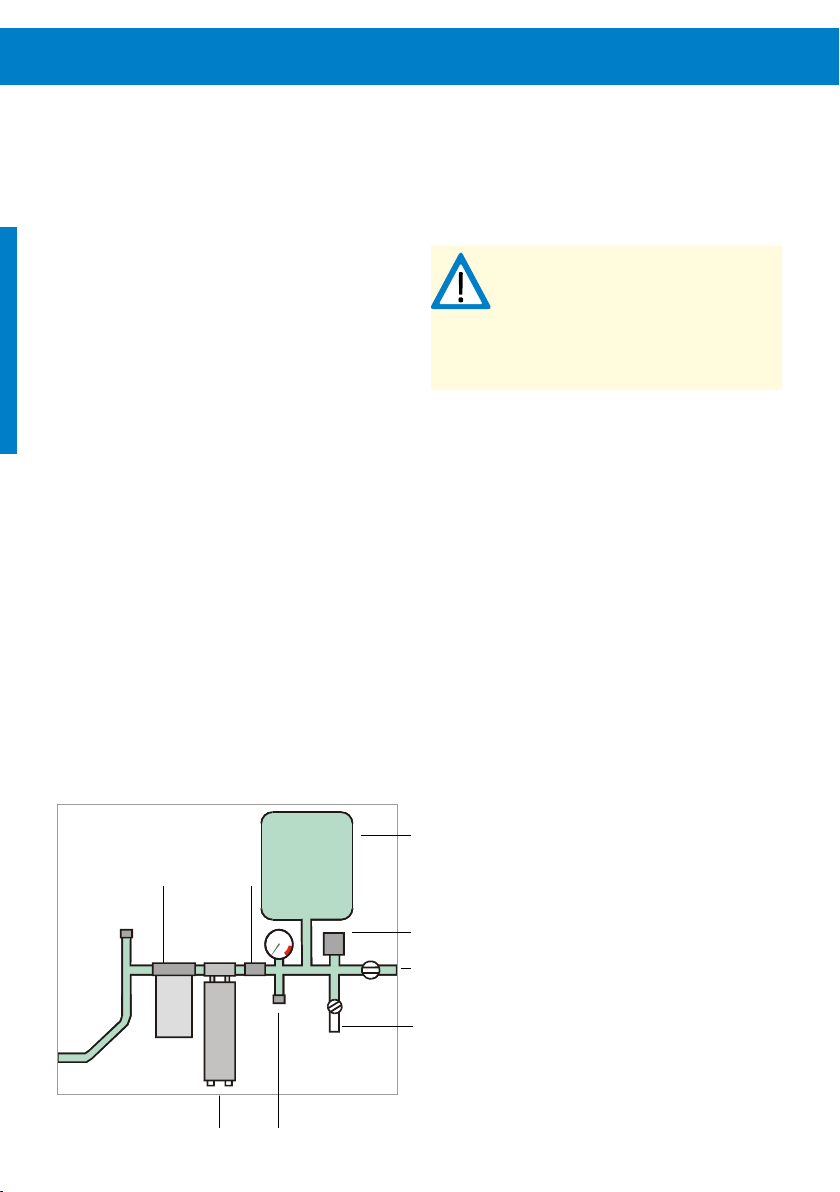
56 Pump Installation
8.6.6 Freeze Protection
Priming the pump – Priming a pump means complete-
ly filling its intake and suction line with water. This must be
done if the pump is mounted higher than the water source.
A removable plug or a valve must be installed at the highest
point in the suction plumbing. Prime the pump and intake
line by pouring water into the opening until it is filled completely. Your foot valve prevents loss of prime by not allowing water to flow back into the water source. The pump will
create sufficient vacuum to self-prime to around 3 m/10 ft
(less at high elevations), but only when it is in new condition
and wet inside. A priming plug is always recommended if
the pump is installed above the water source. Using a good
quality ball valve instead of a plug is recommended, especially if frequent priming is expected.
Check valve at the pump outlet – A check valve at the
pump outlet is required if there is more than a 10 m/30 ft lift
above the pump, or in any pressurizing system. This allows
a more easy start of the pump. It also prevents back flow
when changing filter cartridges.
Pipe unions – If you run rigid piping (copper or PVC) directly to the pump, unions are required. Unions make pump
replacement easy, without the need to cut and re-solder or
re-glue the pipe. “Copper Flex Connectors” commonly used
for water heaters may be used instead.
Figure 20: LORENTZ boost pump installation kit
CAUTION – The pump must be protected
from freezing. Freezing may damage the
pump.
CAUTION – When insulating the pump for
freeze protection the motor must be
excluded to prevent overheating.
pressure tank
inline filter check valve
PS150 Boost
pressure switch
to house plumbing
hose bib
pressure relief valve
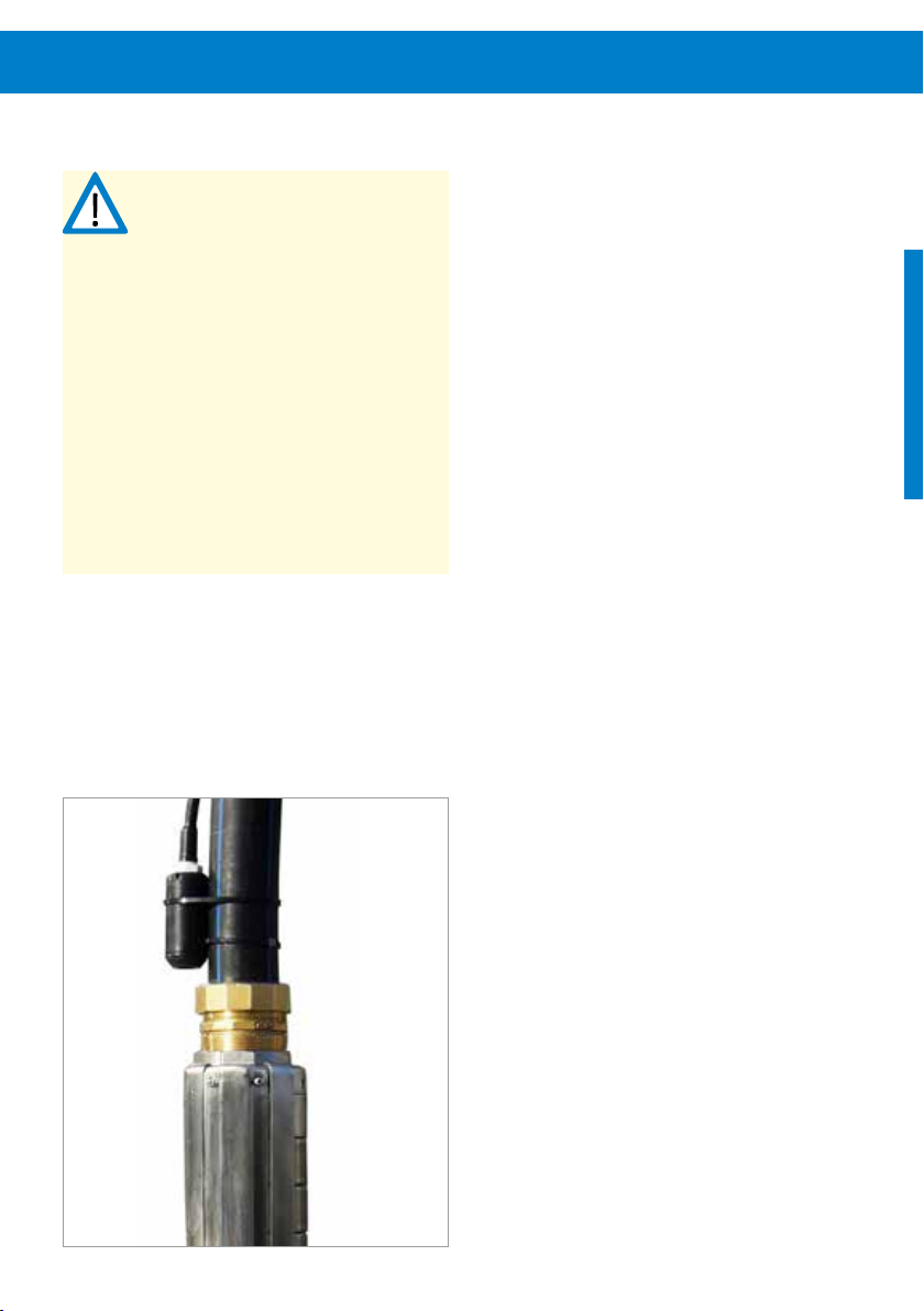
9 Pump Accessories Installation
CAUTION – To avoid multiple starts of the
pump in twilight conditions, the Sun
Sensor module must be installed and
configured for all PS2-1800 CS-F and all
PS2-4000 pump systems. Operating
without a Sun Sensor module can lead to
increased wear or damage to the pump.
Such damage is excluded from the
warranty.
CAUTION – Never let the pump run dry.
Dry running will damage the pump and
void the warranty. LORENTZ requires a dry
run protection for every pump system.
CAUTION – Installing a surge protector at
all switch inputs is recommended,
damaged inputs due to electric surges are
not covered by the warranty.
Figure 21: Well probe fixing
9.1 Well Probe
The well probe contains a mechanical float with a magnet
inside. When the probe is submerged, the float rises, and the
magnet actuates a switch. The switch closes (makes contact)
to indicate the presence of water. If the water level drops
below the probe, the float drops, and the switch opens
(breaks contact): The controller will stop the pump. When
the water level recovers and the switch closes again, the
controller will delay the restart for 15 minutes for the water
level to recover. To force a quick restart, turn the controller
off, then on again. The switch is sealed, so the contacts
never touch the water.
Submersion depth – The maximum submersion depth is
50 meters.
Fixing – Along with the probe two cable ties are provided.
For a pump that is to be installed in a vertical position,
clamp the probe to the pipe just above the pump outlet,
as shown in “Figure 21: Well probe fixing”. Splice the two
wires of the probe using the splice kit components that are
packed with the probe. The assembly procedure is the same
as the main pump splice.
Wiring to the controller – The well probe must be wired
to the controller at terminal 1 and 2, cf. “7.6.3 Pump Accessories Wiring” on page 27.
Potential problems with the well probe in surface
water – The probe has a moving float. It is highly resistant
to deposits and debris. However, the float can become stuck
where algae or water creatures are present in surface water..

58 Pump Accessories Installation
Possible solutions are:
Fix the probe independently of the pump and pipe
(clamped to a weight, but not to the drop pipe). This
way, it can be pulled out for inspection or cleaning
without the need to lift the pump. (This may not be
feasible if the well casing is smaller than 6 in)
Pull the probe out periodically (with the pump, if neces-
sary) for testing and inspection. The pump should stop
a few seconds after the probe leaves the water.
Wrap the probe in a protective screen (fiberglass
window screen, for example).
Use a different type of float switch. You can use any
switch that makes contact on rise (normally open).
Use an encapsulated switch instead of the well probe
if there is enough space for it to operate properly, for
example the LORENTZ float switch.
CAUTION – Never let the pump run dry.
Dry running will damage the pump and
void the warranty. LORENTZ requires a dry
run protection for every pump system.
CAUTION – The well probe must be
positioned vertically, within 10°. If the
pump is not to be installed vertically, find
an alternative way to mount or suspend
the probe, so that it is located higher than
the pump, and in a vertical position.

9.2 Float Switch (Full Tank Shut-off)
We recommend the use of a float switch or other means
to prevent overflow of your tank. This will stop the pump
when the tank is full, then reset when the level drops. This
conserves ground water, prevents overflow, and eliminates
unnecessary pump wear. PS2 controllers allow the use of a
small signal cable to a remote float switch, even if the tank
is a long distance away.
Float switch requirements:
(1) A switch must be used, not wet electrodes.
(2) The preferred system requires a float switch to OPEN
contact on rise to turn the pump OFF. This is called
“normally closed” (N.C.).
Float switch cable requirements:
(3) Two wires are needed.
(4) Minimum wire size 1mm² / AWG 18. This is good for a
distance as far as 600 m / 2,000 ft.
(5) The cable must be suitable for its environment.
(6) If it must run a long distance, use twisted-pair shielded
cable to reduce the chance of damage from light-
ning-induced surge.
Figure 22: Float switch scheme
Grounding shielded float switch cable – If you use
shielded cable, connect the shield to ground at the controller only. Do not ground the shield at the float switch. This
will reduce surges induced by nearby lightning.
Operation of the float switch system – When the
water level is high, the float switch will stop the pump. The
remote switch indicator on the controller will light up. When
the water level drops, the float switch will signal this to the
controller. The indicator light will turn off, and the pump will
restart if sufficient power is available.
Wiring to the controller – The float switch must be
wired to the controller at terminal 3 and 4, cf. “7.6.3 Pump
Accessories Wiring” on page 27.
Manual remote control switch – The float switch circuit
can be used with a manual switch to turn the pump on and
off from a distance. Use any simple on/off switch available
from an electronic supply, electrical supply, or hardware
store (it only carries low voltage, very low current). Wire it
according to the illustration above, for a normally closed
float switch.
sealed
cable clamp
cable
weight
position pump off
pumping
range
position pump on
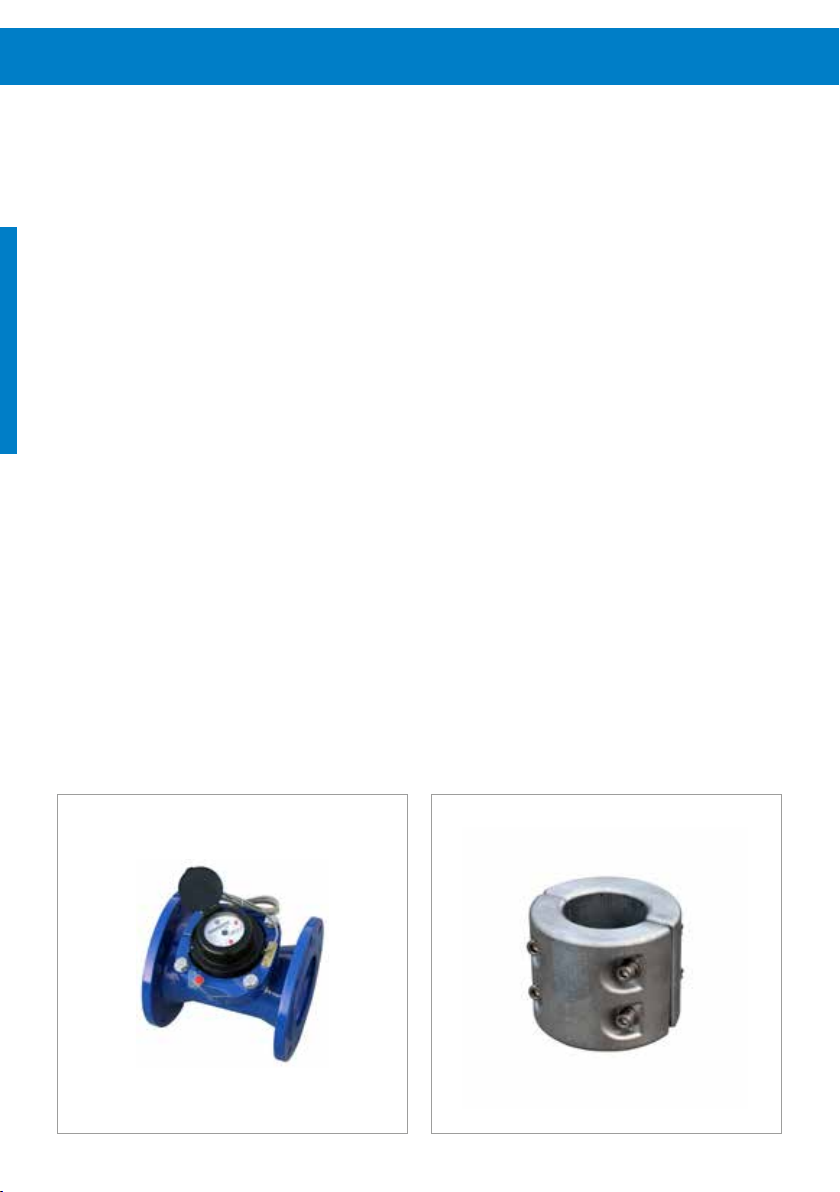
60 Pump Accessories Installation
9.3 Water Meter
For information on the water meter installation, please refer
to the manufactures manual. Pay attention to the installation position, flow direction and the calming section.
Basic rule: The water meter should have 10 nominal
diameters straight pipe ahead of the meter and 5 nominal
straight pipe diameters after to ensure proper flow through
the meter
9.4 Sacrificial Anode
The LORENTZ Sacrificial Anode is designed for use with
LORENTZ pump ends. Where solar pump ends operate in aggressive water conditions acidic water can attacks the passive layer of the high quality-steel pump end. This corrosion
reduces the life time of the product. The LORENTZ Sacrificial
Anode contributes to the protection of the pump system
from this type of corrosion and extends the pumps life.
For further information about the Sacrificial Anode please
refer to the COMPASS datasheet.
Figure 24: LORENTZ Sacrificial AnodeFigure 23: LORENTZ Water Meter
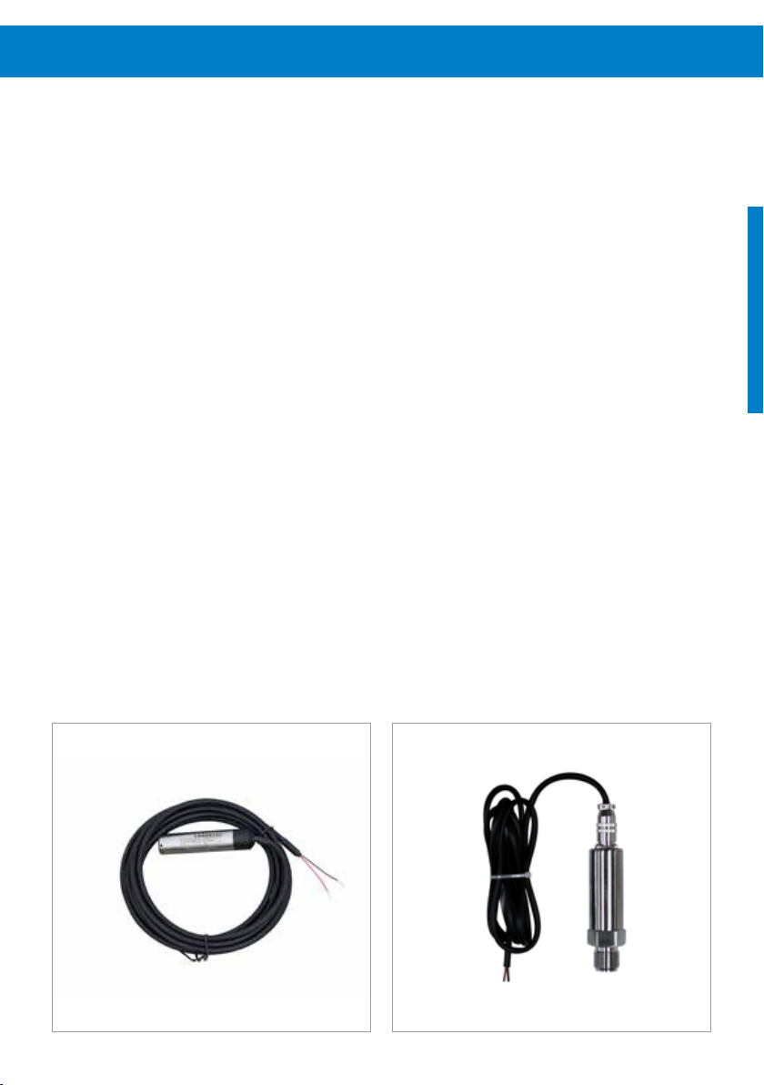
9.5 Liquid Level Sensor
9.6 Pressure Sensor
The LORENTZ range of liquid level sensors use pressure to
measure the level or water in a well or tank. The sensors
can be used for long term water level monitoring and also
for pump control in applications where a well probe cannot
be used.
For further information about the Level sensor please refer
to the COMPASS datasheet.
Figure 25: LORENTZ Liquid Level Sensor Figure 26: LORENTZ Pressure Sensor
The LORENTZ range of liquid pressure sensors are used to
measure the pressure in a pipe. The sensors are commonly
used to measure the pressure at a well head or feeding into
irrigation systems.
For more information about the pressure sensor please refer
to the COMPASS datasheet. Ensure that the pressure sensor
is suitable for your application regarding pressure range and
temperature resistance.

62 Pump Accessories Installation
9.7 Sun Sensor module
CAUTION – To avoid multiple starts of the
pump in twilight conditions, the Sun
Sensor module must be installed and
configured for all PS2-1800 CS-F and all
PS2-4000 pump systems. Operating
without a Sun Sensor module can lead to
increased wear or damage to the pump.
Such damage is excluded from the
warranty.
The LORENTZ Sun Sensor module allows an irradiation level
to be set at which the pump is switched on. This means the
Sun Sensor module will not allow the pump to start until
there is sufficient irradiation to power the pump to the point
of water delivery.
The PS2-1800 and PS2-4000 controllers are supplied with
a special small 1.5 Wp PV module (pre-wired for crimping).
This PV module is used to measure the solar irradiation and
allows you to set irradiation dependent START / STOP values
for the pump.
These settings can only be done via LORENTZ PumpScanner.
(Please check LORENTZ partnerNET and the “PS DataModule and PumpScanner” manual).
Correct Sun Sensor module settings are given in the
COMPASS report, subject to correct parameters. These
settings must be checked on site to make sure that the
parameters entered in COMPASS match the conditions on
site and that the Sun Sensor module is working as intended.
Mount the Sun Sensor module with the same alignment as
the solar array that powers the pump system. For example,
if the solar array is tilted at an angle of 20°, the PV panel
for the Sun Sensor module should be tilted exactly the same.
You can ensure this by mounting the PV module on the
frame of the PV module array.
CAUTION – Do not use any other PV
module than the one available from
LORENTZ or the PS2 controller will be
damaged.
CAUTION – Voltage reversal of the Sun
Sensor module will lead to damage of the
controller.
Figure 27: LORENTZ Sun Sensor module

9.8 Surge Protector
9.9 PV Disconnect with Lightning Surge Protection
CAUTION – Installing a surge protector at
all well probe and remote switch sensor
inputs is recommended, damaged inputs
due to electric surges are not covered by
the warranty.
CAUTION – Surge protectors provide an
extended protection, not a guaranteed
safety. Damages caused by electric surges
are not covered by warranty.
CAUTION – When installing surge
protectors, correct polarity must be
ensured.
Surge protectors are designed to protect electrical devices
from voltage spikes. The surge protectors are to be connected in series to the sensor/input, ideally within the PS
controller case. It can only be used for well probe, remote
switch and water meter terminals. It can not be used for
analog input 1, 2, water sensor and the relay output. For
more information on the surge protector please refer to the
datasheet in COMPASS.
The LORENTZ PV Disconnect series is a PV connection box
with an integrated disconnect switch and optional integrated lightning surge protector. The box is designed to connect
one PV module string (6 strings for the 440-40-6) with the
pump controller by using the terminal clamps located inside
the box. The DC-rated disconnect switch is used as a manual
circuit breaker between the solar array and the load. This
switch is easily accessible by opening the hinged lid at the
bottom spring lock.
The use of a properly sized DC disconnect switch is an
important safety measure and obligatory for a professional
installation of a solar pumping system. The switch must
be installed between the solar generator and the pump
controller. It must meet the electrical requirements of the
connected devices. The PV Disconnect has been designed to
cover the range of PS pump systems PS2-150 to PS2-4000.
Optionally a lightning surge protection device can be
purchased from LORENTZ that fits into a pre-built hole of
the PV Disconnect. It requires proper grounding to fulfil its
protective function. There are a number of different devices
available to suit the voltage level of each controller type.
For more information on installing the PV Disconnect please
refer to the PV Disconnect manual.
Figure 28: Surge Protector
Figure 29: PV Disconnect with surge protection
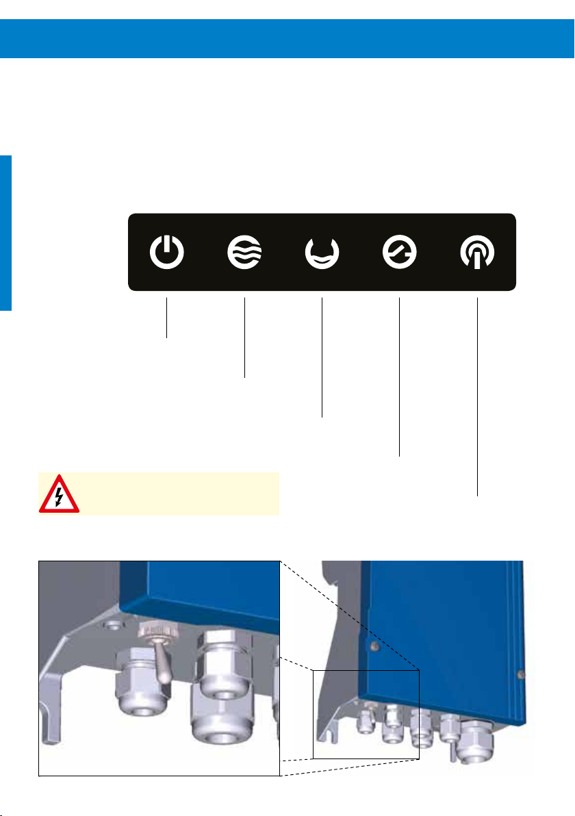
64 Operating the Pump
10 Operating the Pump
This graphic displays the front LED indicators of the PS2
controller. For a detailed description of the LED status
indication please refer to “10.1 LED Status”.
the on/off switch is located at the bottom of the controller.
System status indicator
Pump status indicator
Source low indicator
POWER SWITCH (ON/OFF)
WARNING – The switch only switches
pump operation ON/OFF, it is not a
disconnect switch.
When switched OFF/ON during operation, it resets the
system
Remote switch indicator
Local communication indicator

10.1 LED Status
System status of controller
Pump status indicator
Source low indicator
Remote switch indicator
green light
green light
flashing
no light Insufficient power input
green light Pump is on
green light
flashing
no light Pump is not running
red light Check with PumpScanner
red light
flashing
red light
red light
flashing
no light Water source is okay
red light Remote switch triggered, pump stopped
no light Remote switch not triggered
Power is present, ON/OFF switch is in ON
position
Pump in standby mode due to settings or
ON/OFF switch in OFF position
Flashing frequency indicates pump rpm
Flashing indicates overtemperature of the
controller
Well probe or water sensor has detected a
low water source
Flashing indicates a “source low” incident
since the controller was switched on
Local communication
blue light Bluetooth connection active
blue light
flashing
no light Currently no Bluetooth connection
Update

66 Operating the Pump
Status Description
System (green) – The controller is switched on and
power is available. In low-power conditions, the light
may show even if there is not enough power to run
the pump.
Flashing indicates the pump is not runnung due to
settings, e.g. a timer set up with PumpScanner or the
power switch is in OFF position.
Pump (green) – Pump is running. The sequence of
flashing indicates pump speed (RPM). RPM can be read
off by the flashing sequence of the Pump ON LED:
RPM
LED On > 900
1 flash > 1200
2 flashes > 1600
3 flashes > 2000
4 flashes > 2400
5 flashes > 2800
Pump (red) – An error has occured, please check with
PumpScanner for details.
Flashing indicates that the controller’s thermal protection was triggered due to a too high temperature. The
controller has reduced the motor speed or stopped the
pump. It will automatically speed up or restart after
cooling down.
Source low (red) – The water source has dropped
below the level of the low-water probe or the water
sensor has detected air in the suction pipe. After the
water level recovers or the suction pipe has been refilled with water, the pump will restart after a delay of
15 minutes. Flashing indicates that the controller has
stopped due to a “SOURCE LOW” incident detected
earlier. The number of flashes indicates the number of
incidents (up to three). Toggle the ON/OFF switch to
reset this indicator.
Remote switch (red) – A pump shutdown was trig-
gered by the remote switch wired to terminals 3 and 4.

Controller boot-up sequence
When switching on the power the controller initializes the following LED boot sequence:
Factory reset
After starting the factory reset from PumpScanner all data will be deleted from the controller. This process takes approximately one minute. During that time the controller shows the following LED status and must not be switched off:

68 Operating the Pump
10.2 Starting the Pump
(1) Make sure that an unhindered water flow is possible
and not blocked, e.g. by closed valves.
(2) Switch on the PV generator disconnect switch.
(3) Toggle the power switch on the controller to ON.
A solar-direct pump will now start when sufficient irra-
diation levels are reached and neither the well probe,
remote switch or a PumpScanner setting prevent the
controller from starting the pump.
10.3 Time Delays
Event Time delay
Pump stops due to
insufficient irradiation
Remote switch resets 2 - 3 seconds
Low water well probe
regains contact with water
Shutdown due to
overtemperature
Shutdown due to overload Manual reset of POWER
To force a quick start, the above listed delays can be bypassed by switching the POWER switch OFF/ON. The pump
should now start immediately if sufficient power is present.
120 seconds
15 Minutes
Automatic restart after
cooling down
switch necessary

10.4 Parameter Setting
NOTE – Please always refer to the
PumpScanner documentation available on
partnerNET for the latest developments.
It is highly recommended to make an initial configuration of
the DataModule inside the PS2 controller using LORENTZ
PumpScanner, our Application for Android smartphones.
For optimal performance the pump system must be configured correctly with PumpScanner.
To gain access to the DataModule using PumpScanner,
the installation must be registered online in partnerNET at
“Sites” first. The “License list” within PumpScanner settings
then must be updated.
For detailed instructions on how to set up a “Site”
and how to install and use PumpScanner read the
“PS Datamodule and PumpScanner” manual. It is
available on partnerNET.
NOTE – Always make sure that the latest
version of PumpScanner is installed on
your device. Make sure that the DataModule is equipped with the latest firmware
version. The firmware can be checked and
updated using PumpScanner.
Check whether the latest version of PumpScanner is
installed on your android device. Check the PumpScanner
manual for help.
1. Make sure that the physical installation is completed
and that all connections have been double checked
for correct connection.
2. Connect the power to the PS2 controller but leave the
ON/OFF toggle switch of the PS controller in position
OFF. The pump must not run at this point.
3. Connect to the pump controller using PumpScanner
as per the PumpScanner manual.
4. Check the PS2 controller Firmware version as per
the PumpScanner manual and update it if asked by
PumpScanner to do so.
5. Click on “Pump profile” in PumpScanner to access the
parameter settings for the PS2 controller. Do not forget to scroll to the bottom and SAVE the changes
before leaving the “pump profile” menu.
Controller and pump unit – Use the pull down menu to
select the correct controller and the correct pump unit.
Cable length and cable size – Enter the length and
size of the installed motor cable to allow PumpScanner to
calculate the correct cable losses for the pump system.
Flow meter and pressure sensor – If any Water Meter
or Pressure Sensor is connected to the PS2 controller enter
the characteristics of the sensors as described.
The remaining options are explained in the PumpScanner
manual.
Always click the SAVE Button on the bottom of the pump
profile menu to keep the changes.
The pump profile configuration is done and the pump can
be switched ON.

70 LORENTZ CONNECTED
11 LORENTZ CONNECTED
The LORENTZ CONNECTED portfolio takes water pumping
to the next level. If offers a range of features for monitoring
and managing pumps, even remotely over the internet.
CONNECTED - a new water pumping experience.
11.1 DataModule
The LORENTZ PS DataModule is an integrated data logger
and remote control device for the whole PS2 range of
helical, centrifugal and surface pumps. Together with the
PumpScanner App for Android™, the LORENTZ Communicator and pumpMANAGER, the PS DataModule opens
new opportunities in drinking water supply for people and
livestock, irrigation and swimming pool applications. The PS
DataModule collects performance data from the pump system and stores it for periodic collection. It uses Bluetooth™
to communicate with the LORENTZ PumpScanner Android™
App and via Communicator with the browser based pumpMANAGER service, allowing secure data collection without
physical connections.
The PS DataModule opens up new opportunities to improve
customer service, knowledge and certainty.
11.2 PumpScanner
PumpScanner allows you and your customers to monitor
and manage your PS, PS2 and PSk2 solar pumps from a
smartphone or tablet. This exciting development for the
LORENTZ pump systems is a clear differentiator from the
competitor offerings.
PumpScanner will give you detailed information about the
pumps’ operational status and help you to fault find any
problems more effectively, so saving you money, time and
effort. You can download PumpScanner and see the demo
features today without any additional equipment.
PumpScanner runs on the Android™ operating system
which is found in many smart phones and tablets. More
information is available on LORENTZ partnerNET at
www.lorentz.de/en/partnernet/support/pumpscanner
and at www.lorentz.de/connected.

11.3 PS Communicator & pumpMANAGER
The LORENTZ PS Communicator and pumpMANAGER
service combine to offer customers a cost effective full management and monitoring system for their LORENTZ pump
estate. This is attractive to commercial farms, industrial
processes, government or NGO monitoring and anywhere
that water is critical to people, livestock or crops.
The PS Communicator sends data from each pump across
the cellular (mobile) data network to a secure central
web server application called pumpMANAGER. The
pumpMANAGER application can be accessed from any web
connected device anywhere in the world making access to
information and control of your solar pumps simple and
convenient. As the connection is two way the pumps can
be programmed, speed controlled or switched off, providing
full remote control. The pumpMANAGER application also
monitors the status of your LORENTZ pump systems and will
alert you if there are any unexpected events.
You can login to pumpMANAGER at www.lorentz.de using
your standard partnerNET credentials and see the demo features today without any addtional equipment or investment.
Figure 30: pumpMANAGER view of installation site Figure 31: pumpMANAGER view of system details
72 Troubleshooting
12 Troubleshooting
Please read this section carefully in case you experience any
problems with the pump system and follow the checklists.
Should technical support by LORENTZ become necessary,
always provide the model and serial numbers.
12.1 Pump does not run
Most problems are caused by either wrong cable connections (in a new installation) or failed connections, especially
insufficiently tightened cables that come loose from a terminal. Please check the wiring. The System status light will
indicate that the system is switched on and a power source
is connected to the controller. It indicates that voltage
is present but in a solar-direct system there may not be sufficient power to start the pump. In this case it will attempt a
restart every 120 seconds.
12.2 Pump attempts a Restart every 120 Seconds
The controller will emit a low noise as it tries to start the
pump. The pump will start to turn or only vibrate a little.
(1) There may be insufficient power reaching the controller.
A solar-direct (non-battery) system should start if there
is sufficient sun to cast a slight shadow. A battery
system should start if the supply voltage is higher than
what is listed in “Set points for low voltage disconnect”
on page 29.
(2) If the pump was recently connected (or reconnected)
to the controller, it may be running in reverse direction
due to a wiring error.
(3) If the motor shaft only vibrates but does not turn, it
may have power on only two of the three motor wires.
This will happen if there is a broken connection or if
you accidentally interchanged one of the power wires
with the ground wire.
(4) The pump or pipe may be blocked by mud, clay, sand
or debris
CAUTION – if the pump is blocked, it has
to be cleaned. Repeated starting of a
blocked pump may cause damage to the
motor. This will void the warranty.
12.3 Flow Rate is to low
Check if the pipeline dimensions are correct as pressure
losses will reduce the flow. Ensure that there is no leakage
in the pipeline.

12.4 General checklist
Check the PV generator
Make sure the PV generator is facing the sun and there is no
partial shading of the array. A partial shading of as little as
10% of the arrays’ surface can stop the pump.
Check all wires and connections
Carefully check for improper wiring (especially in a new
installation) and wiring condition. Wires are often damaged
by animals if they are not enclosed in conduit (pipe). Pull on
wires slightly to check for failed connections.
Check the controller
(1) Loosen the screws from the front of the controller to
access the terminal block where the wires connect.
(2) Check for a burnt smell. This will indicate a failure
of the electronics. Look for burnt wires, bits of black
debris, and any other signs of lightning damage.
(3) Inspect the grounding wires and connections. Most
controller failures are caused by an induced surge from
nearby lightning where the system is not effectively
grounded. Ground connections must be properly made
and free of corrosion.

74 Troubleshooting
Check the dry running protection
If the controller indicates “source low” when the pump is
submerged in water or draws from a sufficient water source,
check the dry running protection system. The probe is
mounted on, or near the pump. If inspection is not feasible,
you can measure the well probe for continuity with a
multimeter. The Well Probe should show continouity when it
is submerged in the water.
Check the float switch
If the controller indicates “remote switch” when the storage
tank is not full, inspect the float switch system. If your
system has a float switch, it will be mounted in the tank. If
inspection is not feasible, you can bypass the switch or test
it electrically.
Force a quick start
If you restore a connection or bypass the probe or float
switch, there is no need to wait for the normal time delay.
Manually switch the on/off switch (or the power source) off
and on to reset the system. The pump should start immediately if sufficient power is present.
If the pump responds to the bypass tests but not to the float
switch, the wires may be shorted (touching each other) or
open (broken) or the switch may be stuck with debris, or out
of its correct position.
Quick checklist
Make sure
(1) the pump is suited for the total lift that is required.
(2) the “max. RPM” adjustment in PumpScanner is not the
reason for perceived low pump performance.
(3) the solar array is receiving sufficient sun light without
shading on the modules, the PV generator is oriented
properly and tilted at the correct angle. Inspect and test
the PV generator circuit and the controller output, as
stated. Take notes of your measurements.
(4) all wires and pipe runs are sized adequately for the
respective distance.
(5) there is no leak in the output pipe from the pump.
Could the issue not be resolved, please raise a service
case with LORENTZ including the service support forms
available on partnerNET, model and serial numbers and your
measurements.


FRANÇAIS

2
Introduction
Merci d’avoir acheté un système de pompe LORENTZ. LORENTZ a placé très haut la barre de la qualité, de l’efficacité
et de la durée de vie des pompes solaires.
Avant de commencer: tous les systèmes de pompe sont équipés de plaques signalétiques qui contiennent toutes les
données importantes. Vérifier les numéros de modèle de tous les composants du système pour s’assurer qu’il s’agit des
articles commandés et que l’emballage est intact et non endommagé. Pour des performances optimales du système et pour
éviter tout dommage, lire et suivre attentivement les instructions d’installation.
Mode d’utilisation de ce guide: ce manuel ne couvre que l’installation du système. Suivre attentivement les instructions
pour une installation sécurisée et durable. La disposition du système doit être planifiée par avance. Il est conseillé d’utiliser le
logiciel LORENTZ COMPASS pour bien dimensionner le système de pompe.
SITES: il est vivement conseillé d’enregistrer l’installation dans SITES sur LORENTZ partnerNET. SITES fournit une
présentation rapide de tous les systèmes de pompe installés, incluant les numéros de série et les détails de l’installation.
Ce sont des informations essentielles en cas de problèmes qui simplifieront grandement le dépannage et les thèmes
degarantie.
Présentation de l’installation
Cette présentation de l’installation est fournie pour se familiariser avec les étapes types à suivre au cours de l’installation
d’un système de pompage solaire d’eau. Chaque installation peut demander que les étapes soient exécutées dans un ordre
différent. Il convient de lire la totalité du manuel avant de réaliser la première installation.
ATTENTION – La présentation de cette installation ne remplace pas les instructions détaillées
dansce manuel. Lire et suivre attentivement le manuel pour s’assurer d’un fonctionnement fiable
et d’une longue durée de vie du produit et pour ne pas mettre en danger la santé et la vie des
personnes.

1. Installation PV et du contrôleur
Suivre les instructions du fabricant pour l’installation PV.
Chaque installation PV doit être équipée d’un sectionneur
PV. Des sectionneurs adaptés sont disponibles auprès de
LORENTZ.
Installer le contrôleur à proximité du panneau PV dans un
endroit à l’ombre pour minimiser la longueur du câble du
côté de l’entrée.
2. Installation électrique
1. Câblage de la pompe: l’ECDrive doit être branché
aux bornes L1, L2, L3 et au raccord de mise à la terre
situé sous la carte de circuit imprimé. Observer le sens de
rotation.
2. Câblage des accessoires: raccorder aux bornes
1et2 un dispositif de protection en cas de trop faible
niveau d'eau dans la source (impératif). Des interrupteurs
de contrôle à distance doivent être raccordés aux bornes
3et 4, des compteurs d'eau aux bornes 5 et 6, des capteurs
4–20mA aux bornes 7 et 8 ou 9 et 10, des détecteurs
d'eau aux bornes 13, 14 et 15 et le module Sun Sensor
aux bornes 16 et 17. Les bornes 11 et 12 constituent un
relais-commutateur à contact de sortie.
3. Câblage de l’entrée c.c.: brancher la borne positive
du panneau PV au +, et la borne négative au −. Respecter
la tension d’entrée max. Si le contrôleur est branché sur
une batterie, alors le mode batterie doit être activé dans
PumpScanner.
Se reporter à «Sectionneur CC» page17 pour obtenir
plus d’informations sur les conditions que le sectionneur PV
doit satisfaire.
Pour plus de détails, se reporter à «7.5 Exigences de
montage, d’espace et de ventilation» page19.
Pour plus de détails, se reporter à «7.6.2 Câblage de la
pompe» page26.
Pour plus de détails, se reporter à «7.6.3 Câblage des
accessoires de la pompe» page27.
Pour plus de détails, se reporter à «7.6.4 Câblage d’entrée
pour les systèmes sansbatterie» page28.
4. Mise à la terre: un conducteur de protection doit être
relié au point de mise à la terre situé sous la carte de
circuit imprimé.
3. Installation de la pompe
Pompes immergées: faire descendre avec précaution la
pompe dans la source d’eau, à l’aide d’un filin de sécurité.
Pompes de surface: installer la pompe de surface sur
des fondations adéquates avec un dimensionnement des
tuyaux suffisant pour assurer un fonctionnement efficace.
Remplir la pompe d’eau propre avant de la démarrer.
Pour plus de détails, se reporter à «7.6.6 Mise à la terre»
page30.
Pour plus de détails, se reporter à «8.3 Pompes
immergées» page34.
Selon le système de pompe, se reporter à «8.4 Pompes de
surface CS-F» page39 ou «8.3 Pompes immergées»
page34 pour obtenir des informations détaillées.

4 Contenu Contenu 5
1 Déclaration de conformité . . . . . . . . . . . . . . . . . . . . . . . . . . . . . . . . . . . . . . 6
2 Réception, stockage et manipulation . . . . . . . . . . . . . . . . . . . . . . . . . . . . . . . . 6
3 Spécification des produits . . . . . . . . . . . . . . . . . . . . . . . . . . . . . . . . . . . . . . 7
3.1 Généralités . . . . . . . . . . . . . . . . . . . . . . . . . . . . . . . . . . . . . . . . . . . . . . . . . . . 7
3.2 Caractéristiques . . . . . . . . . . . . . . . . . . . . . . . . . . . . . . . . . . . . . . . . . . . . . . . . . 7
3.3 Accréditations/Certifications . . . . . . . . . . . . . . . . . . . . . . . . . . . . . . . . . . . . . . . . . .7
3.4 Dénomination . . . . . . . . . . . . . . . . . . . . . . . . . . . . . . . . . . . . . . . . . . . . . . . . .8
4 Conditions de fonctionnement . . . . . . . . . . . . . . . . . . . . . . . . . . . . . . . . . . . . 9
5 Instructions de sécurité . . . . . . . . . . . . . . . . . . . . . . . . . . . . . . . . . . . . . . .10
6 Schémas de conception et de dimensionnement d’un système de pompe . . . . . . . . . . . . .12
6.1 Dimensionnement d’un système de pompe . . . . . . . . . . . . . . . . . . . . . . . . . . . . . . . . . . 12
6.2 Conception du système: pompes immergées . . . . . . . . . . . . . . . . . . . . . . . . . . . . . . . . . 13
6.3 Conception du système: pompes de surface . . . . . . . . . . . . . . . . . . . . . . . . . . . . . . . . . 14
6.4 Conception du système: pompes Boost de surface . . . . . . . . . . . . . . . . . . . . . . . . . . . . . . 15
7 Installation du contrôleur . . . . . . . . . . . . . . . . . . . . . . . . . . . . . . . . . . . . . .16
7.1 Généralités . . . . . . . . . . . . . . . . . . . . . . . . . . . . . . . . . . . . . . . . . . . . . . . . . . 16
7.2 Éléments du contrôleur . . . . . . . . . . . . . . . . . . . . . . . . . . . . . . . . . . . . . . . . . . . . 18
7.3 Données techniques du contrôleur . . . . . . . . . . . . . . . . . . . . . . . . . . . . . . . . . . . . . . 18
7.4 Mise en place du contrôleur . . . . . . . . . . . . . . . . . . . . . . . . . . . . . . . . . . . . . . . . . . 19
7.5 Exigences de montage, d’espace et de ventilation . . . . . . . . . . . . . . . . . . . . . . . . . . . . . . . 19
7.6 Câblage du contrôleur . . . . . . . . . . . . . . . . . . . . . . . . . . . . . . . . . . . . . . . . . . . . 21
7.6.1 Description des bornes . . . . . . . . . . . . . . . . . . . . . . . . . . . . . . . . . . . . . . . 22
7.6.2 Câblage de la pompe . . . . . . . . . . . . . . . . . . . . . . . . . . . . . . . . . . . . . . . . 26
7.6.3 Câblage des accessoires de la pompe . . . . . . . . . . . . . . . . . . . . . . . . . . . . . . . . 27
7.6.4 Câblage d’entrée pour les systèmes sansbatterie . . . . . . . . . . . . . . . . . . . . . . . . . . 28
7.6.5 Câblage d’entrée pour les systèmes à batterie . . . . . . . . . . . . . . . . . . . . . . . . . . . . 29
7.6.6 Mise à la terre . . . . . . . . . . . . . . . . . . . . . . . . . . . . . . . . . . . . . . . . . . . 30
7.7 Systèmes de pompage pour piscine PS2 . . . . . . . . . . . . . . . . . . . . . . . . . . . . . . . . . . . . 31
7.8 Systèmes de pompage boost PS2 . . . . . . . . . . . . . . . . . . . . . . . . . . . . . . . . . . . . . . . 31
8 Installation de la pompe . . . . . . . . . . . . . . . . . . . . . . . . . . . . . . . . . . . . . . .32
8.1 Instructions générales . . . . . . . . . . . . . . . . . . . . . . . . . . . . . . . . . . . . . . . . . . . . . 32
8.1.1 Dimensionnement des tuyaux . . . . . . . . . . . . . . . . . . . . . . . . . . . . . . . . . . . . 32
8.1.2 Épissurage des câbles . . . . . . . . . . . . . . . . . . . . . . . . . . . . . . . . . . . . . . . . 33
8.2 Type de système de pompe . . . . . . . . . . . . . . . . . . . . . . . . . . . . . . . . . . . . . . . . . . 33
8.3 Pompes immergées . . . . . . . . . . . . . . . . . . . . . . . . . . . . . . . . . . . . . . . . . . . . . . 34
8.3.1 Câblage de la pompe . . . . . . . . . . . . . . . . . . . . . . . . . . . . . . . . . . . . . . . . 34
8.3.2 Installation et manipulation . . . . . . . . . . . . . . . . . . . . . . . . . . . . . . . . . . . . 36
8.3.3 Profondeur d’installation . . . . . . . . . . . . . . . . . . . . . . . . . . . . . . . . . . . . . . 37
8.3.4 Retrait . . . . . . . . . . . . . . . . . . . . . . . . . . . . . . . . . . . . . . . . . . . . . . 37
8.3.5 Caractéristiques supplémentaires . . . . . . . . . . . . . . . . . . . . . . . . . . . . . . . . . . 38
8.3.5.1 Filin de sécurité . . . . . . . . . . . . . . . . . . . . . . . . . . . . . . . . . . . . . . 38
8.3.5.2 Tuyaux en plastique . . . . . . . . . . . . . . . . . . . . . . . . . . . . . . . . . . . . 38
8.4 Pompes de surface CS-F . . . . . . . . . . . . . . . . . . . . . . . . . . . . . . . . . . . . . . . . . . . . 39
8.3.5.3 Tube de décantation. . . . . . . . . . . . . . . . . . . . . . . . . . . . . . . . . . . . 38
8.4.1 Mise en place et fondations . . . . . . . . . . . . . . . . . . . . . . . . . . . . . . . . . . . . . 39
8.4.2 Câblage du moteur de la pompe . . . . . . . . . . . . . . . . . . . . . . . . . . . . . . . . . . 40
8.4.3 Installation et manipulation . . . . . . . . . . . . . . . . . . . . . . . . . . . . . . . . . . . . . 41

Contenu 5
8.4.4 Hauteur d’aspiration . . . . . . . . . . . . . . . . . . . . . . . . . . . . . . . . . . . . . . . . 42
8.4.5 Démarrage initial . . . . . . . . . . . . . . . . . . . . . . . . . . . . . . . . . . . . . . . . . . 43
8.4.5.1 Remplissage en eau de la pompe . . . . . . . . . . . . . . . . . . . . . . . . . . . . . 43
8.4.5.2 Sens de rotation . . . . . . . . . . . . . . . . . . . . . . . . . . . . . . . . . . . . . . 44
8.5 Pompes Boost pour piscine . . . . . . . . . . . . . . . . . . . . . . . . . . . . . . . . . . . . . . . . . . 45
8.6 Pompes Boost de surface . . . . . . . . . . . . . . . . . . . . . . . . . . . . . . . . . . . . . . . . . . . 52
9 Installation des accessoires de lapompe . . . . . . . . . . . . . . . . . . . . . . . . . . . . . .57
9.1 Sonde de puits . . . . . . . . . . . . . . . . . . . . . . . . . . . . . . . . . . . . . . . . . . . . . . . . 57
9.2 Interrupteur à flotteur (arrêt de réservoir plein) . . . . . . . . . . . . . . . . . . . . . . . . . . . . . . . . 59
9.3 Compteur d’eau . . . . . . . . . . . . . . . . . . . . . . . . . . . . . . . . . . . . . . . . . . . . . . . 60
9.4 Anode sacrificielle . . . . . . . . . . . . . . . . . . . . . . . . . . . . . . . . . . . . . . . . . . . . . . 60
9.5 Capteur de niveau de liquide . . . . . . . . . . . . . . . . . . . . . . . . . . . . . . . . . . . . . . . . . 61
9.6 Capteur de pression. . . . . . . . . . . . . . . . . . . . . . . . . . . . . . . . . . . . . . . . . . . . . . 61
9.7 Module SunSensor . . . . . . . . . . . . . . . . . . . . . . . . . . . . . . . . . . . . . . . . . . . . . . 62
9.8 Dispositif de protection contre les surtensions . . . . . . . . . . . . . . . . . . . . . . . . . . . . . . . . . 63
9.9 Sectionneur PV avec dispositif de protection contre les surtensions dues à la foudre . . . . . . . . . . . . . . 63
8.4.5.3 Vérification finale . . . . . . . . . . . . . . . . . . . . . . . . . . . . . . . . . . . . . 44
8.5.1 Mise en place et fondations . . . . . . . . . . . . . . . . . . . . . . . . . . . . . . . . . . . . . 45
8.5.2 Dimensionnement des tuyaux . . . . . . . . . . . . . . . . . . . . . . . . . . . . . . . . . . . . 46
8.5.3 Installation et manipulation . . . . . . . . . . . . . . . . . . . . . . . . . . . . . . . . . . . . . 47
8.5.4 Démarrage initial . . . . . . . . . . . . . . . . . . . . . . . . . . . . . . . . . . . . . . . . . . 48
8.5.4.1 Remplissage en eau de la pompe . . . . . . . . . . . . . . . . . . . . . . . . . . . . . 48
8.5.4.2 Sens de rotation . . . . . . . . . . . . . . . . . . . . . . . . . . . . . . . . . . . . . . 49
8.5.4.3 Vérification finale . . . . . . . . . . . . . . . . . . . . . . . . . . . . . . . . . . . . . 49
8.5.5 Service et maintenance . . . . . . . . . . . . . . . . . . . . . . . . . . . . . . . . . . . . . . . 50
8.5.5.1 Maintenance générale . . . . . . . . . . . . . . . . . . . . . . . . . . . . . . . . . . . 50
8.5.5.2 Nettoyage du filtre . . . . . . . . . . . . . . . . . . . . . . . . . . . . . . . . . . . . 50
8.5.5.3 Utilisation avec de l’eau salée ou de l’eau de mer . . . . . . . . . . . . . . . . . . . . . 50
8.5.5.4 Remplacement du joint mécanique . . . . . . . . . . . . . . . . . . . . . . . . . . . . 51
8.6.1 Mise en place et fondations . . . . . . . . . . . . . . . . . . . . . . . . . . . . . . . . . . . . . 52
8.6.2 Câblage du moteur de la pompe . . . . . . . . . . . . . . . . . . . . . . . . . . . . . . . . . . 52
8.6.3 Position d’installation . . . . . . . . . . . . . . . . . . . . . . . . . . . . . . . . . . . . . . . . 53
8.6.4 Filtration . . . . . . . . . . . . . . . . . . . . . . . . . . . . . . . . . . . . . . . . . . . . . . 54
8.6.5 Conception de la plomberie . . . . . . . . . . . . . . . . . . . . . . . . . . . . . . . . . . . . . 55
8.6.6 Protection contre le gel . . . . . . . . . . . . . . . . . . . . . . . . . . . . . . . . . . . . . . . 56
10 Fonctionnement de la pompe . . . . . . . . . . . . . . . . . . . . . . . . . . . . . . . . . . . .64
10.1 Voyants d’état . . . . . . . . . . . . . . . . . . . . . . . . . . . . . . . . . . . . . . . . . . . . . . . . 65
10.2 Démarrage de la pompe . . . . . . . . . . . . . . . . . . . . . . . . . . . . . . . . . . . . . . . . . . . 68
10.3 Constantes de temps . . . . . . . . . . . . . . . . . . . . . . . . . . . . . . . . . . . . . . . . . . . . . 68
10.4 Réglage des paramètres. . . . . . . . . . . . . . . . . . . . . . . . . . . . . . . . . . . . . . . . . . . . 69
11 LORENTZ CONNECTED . . . . . . . . . . . . . . . . . . . . . . . . . . . . . . . . . . . . . . . .70
11.1 DataModule . . . . . . . . . . . . . . . . . . . . . . . . . . . . . . . . . . . . . . . . . . . . . . . . . 70
11.2 PumpScanner . . . . . . . . . . . . . . . . . . . . . . . . . . . . . . . . . . . . . . . . . . . . . . . . . 70
11.3 PS Communicator et pumpMANAGER . . . . . . . . . . . . . . . . . . . . . . . . . . . . . . . . . . . . . 71
12 Dépannage . . . . . . . . . . . . . . . . . . . . . . . . . . . . . . . . . . . . . . . . . . . . . .72
12.1 La pompe ne fonctionne pas . . . . . . . . . . . . . . . . . . . . . . . . . . . . . . . . . . . . . . . . . 72
12.2 La pompe tente de redémarrer toutes les 120secondes. . . . . . . . . . . . . . . . . . . . . . . . . . . . . 72
12.3 Débit trop faible . . . . . . . . . . . . . . . . . . . . . . . . . . . . . . . . . . . . . . . . . . . . . . . 72
12.4 Liste de contrôle générale . . . . . . . . . . . . . . . . . . . . . . . . . . . . . . . . . . . . . . . . . . . 73

6 Déclaration de conformité
1 Déclaration de conformité
La société BERNT LORENTZ GmbH & Co. KG Allemagne,
déclare sous son entière responsabilité que les produits
PS2-150 Boost, PS2-150 C, PS2-0 HR, PS2-200 HR,
PS2-600 HR, PS2-600 C, PS2-600 CS-F, PS2-600 Pool
CS-17-1, PS2-1800 HR, PS2-1800 C, PS2-1800 CS-F,
PS2-1800 Pool CS-37-1, PS2-4000 HR, PS2-4000 C,
PS2-4000 CS-F
auxquels la présente déclaration se réfère, sont conformes
aux directives du Conseil concernant le rapprochement des
législations des États membres de l’UE relatives aux:
Machines (2006/42/CE)
Compatibilité électromagnétique (2014/30/EU)
Équipement électrique conçu pour fonctionner avec
certaines limites de tension (2014/35/EU)
BERNT LORENTZ GmbH & Co. KG
Siebenstücken 24
24558 Henstedt-Ulzburg
Allemagne
1er janvier 2016
2 Réception, stockage et
manipulation
Vérifier à la réception que l’emballage est intact et non
endommagé. Pour toute anomalie détectée, contacter le
fournisseur.
Les pompes LORENTZ sont expédiées de l’usine dans un
emballage approprié dans lequel elles doivent rester jusqu’à
leur installation. Manipuler la pompe avec soin et éviter
tout choc et impact inutiles.
Tout stockage intermédiaire prolongé dans un environnement se caractérisant par une forte humidité et des
températures variables doit être évité. L’humidité et la
formation de condensation peuvent endommager les
parties métalliques. Une non-conformité peut annuler la
garantie. Il est recommandé de stocker les pièces dans une
pièce fermée et sèche.
Le moteur, la tête de pompe et le contrôleur peuvent être
stockés (inutilisés) dans une plage de -20°C à +65°C
(-4°F à +149°F). Les composants ne doivent pas être
exposés à la lumière directe du soleil.
Bernt Lorentz, PDG

3 Spécification des produits
3.1 Généralités
Les systèmes de pompe solaires de surface et immergées
LORENTZ sont conçus pour fournir efficacement d’importants volumes d’eau, et ce uniquement avec de l’énergie
solaire. Ils sont habituellement utilisés pour des projets
d’irrigation et pour des applications d’eau potable à grande
échelle où ils répondent de manière sûre aux exigences les
plus pointues, d’un point de vue économique, sans générer
de pollution et sans raccord au réseau ou générateur diesel.
Un système de pompe solaire type est composé d’un générateur pour panneaux PV, d’une pompe et d’un contrôleur
de pompe solaire. Reposant sur le principe qu’il est plus
efficace de stocker de l’eau plutôt que de l’électricité, le
système ne possède aucun dispositif de stockage d’énergie
tel qu’un accumulateur électrique comme dans un système
de pompe solaire standard.
Le générateur PV, accumulation de plusieurs modules PV
raccordés en série et en parallèle, absorbe le rayonnement
solaire et le transforme en énergie électrique, fournissant
de l’énergie à l’ensemble du système. Le contrôleur de la
pompe contrôle et règle le fonctionnement du système; il
paramètre la fréquence de sortie en temps réel en fonction
de la variation de l’intensité d’ensoleillement, afin d’obtenir
une optimisation de puissance (MPPT).
Chaque système de pompe LORENTZ est composé d’une
tête de pompe, d’un moteur de pompe et d’un contrôleur.
Ce concept modulaire garde tous les composants électroniques au-dessus du niveau du sol, même pour les pompes
immergées, afin de faciliter l’entretien et de réduire le coût
d’exploitation.
3.2 Caractéristiques
Caractéristiques des pompes LORENTZ:
Conçues en Allemagne avec des matériaux haute qualité
non corrodables
Boîtier du contrôleur résistant à la corrosion selon la
norme IP65/ NEMA 3A
Contrôle de la pompe basé sur l’énergie disponible
Moteurs CC sans balais ECDRIVE, tout particulièrement
conçus pour une utilisation solaire avec jusqu’à 92%
d’efficacité
Surveillance et gestion incluant un système embarqué
d’enregistrement pour jusqu’à 5ans de données de
performance, un accès intelligent aux appareils via
l’application Android™ PumpScanner et l’intégration
au service de gestion à distance pumpMANAGER de
LORENTZ disponible en option.
3.3 Accréditations/Certifications
Les systèmes LORENTZPS2 sont vendus dans plus de
130pays. Les versions et exigences en matière d'accréditations divergeront d'un pays à l'autre. Se référer à l'étiquette
apposée sur le contrôleur pour s'assurer de la version exacte
et des marquages signalant les accréditations. Les certificats
d'accréditation complets sont disponibles sur PartnerNET.

8 Spécification des produits
3.4 Dénomination
Définition du modèle de pompe pour les
pompesimmergées:
Pour les pompes centrifuges
C
- SJ 60 - 2 - 2
Nombre de petites turbines
Étages
Débit (m³/h)
Immergée
Centrifuge
Pour les pompes à rotor hélicoïdal
HR
- 23 H/HH/L - 1
Classe de température
Élévation importante /
élévation très importante /
long rotor
Débit nominal (cm³/tour)
Pompe à rotor hélicoïdal
Pour les pompes de piscine
CS
- 37 - 1
Définition du modèle de pompe pour les
pompesdesurface:
Pour les pompes CS-F1 à CS-F20
CS
- F 4 - 3
Étages
Débit (m³/h)
Pompe verticale
multi-étagée
Surface centrifuge
Pour les pompes CS-F32 à CS-F85
CS
- F 32 - 60 - 2
Nombre de petites turbines
Étages x 10
Débit (m³/h)
Pompe verticale multi-étagée
Surface centrifuge
Pour les pompes Boost
Boost
- 330
Nombre d’impulseurs
Débit nominal (m³)
Surface centrifuge
Débit nominal (GPH)
Pompe de surface à vanne
à déplacement positif

4 Conditions de fonctionnement
Conditions ambiantes: les systèmes de pompe PS2
peuvent fonctionner jusqu'à une altitude de 3000m
au-dessus du niveau de la mer et à une température
ambiante de 50°C maximum. Si la température atteint la
valeur limite, l'alimentation électrique est automatiquement
réduite. Le contrôleur PS2 a été conçu pour une utilisation
dans des environnements correspondant au degré de
pollution3, conformément à la norme IEC-664-1: Présence
d'une pollution conductrice ou d'une pollution sèche, non
conductrice, qui devient conductrice par suite de la condensation qui peut se produire.
Liquide: les pompes centrifuges et à rotor hélicoïdal (HR)
LORENTZPS2 peuvent être utilisées pour l’approvisionnement en eau potable, les abreuvoirs et les systèmes d’irrigation ne contenant pas de particules solides ou à longues
fibres d’une taille supérieure à celle de grains de sable, d’un
diamètre maximal de 2mm. La teneur en sable maximale
autorisée est de 50ppm; une teneur plus élevéeréduirait
considérablement la durée de vie de la pompe enraison de
l’usure. La teneur en sel maximale est de 300-500ppm à
une température maximale de 30°C/85°F. Les défectuosités
dues au pompage d’autres liquides ne sont pas couvertes
par la garantie.
Les pompes de piscine LORENTZPS2 peuvent être utilisées
dans de l'eau chlorurée, de l'eau de mer et de l'eau salée.
Lorsqu’elle est utilisée dans des piscines à eau salée et
eau de mer, la pompe doit être inspectée et nettoyée
régulièrement.
Les pompes LORENTZPS2BOOST peuvent être utilisées
pour les applications d’eau propre uniquement. L’eau ne
doit contenir aucune particule abrasive. Il est vivement
recommandé d’installer un filtre d’entrée pour protéger la
pompe de toute intrusion de poussière. Se reporter à
«8.6.4 Filtration» page54 pour plus d’informations.
Température du liquide: selon le type de système de
pompe LORENTZ, différentes exigences s’appliquent aux
températures du liquide:
PS2 centrifuge immergée – La température maximale
du liquide pour les pompes centrifuges immergées est de
+50°C (122°F).
PS2 centrifuge de surface – La température maximale
du liquide pour les pompes centrifuges de surface est de
+70°C (158°F).
PS2 centrifuge de piscine – La température maximale du
liquide pour les pompes de piscine est de +60°C (140°F).
PS2Boost de surface – La température maximale du
liquide pour les pompes Boost est de +80°C (176°F).
PS2 à rotor hélicoïdal (HR) immergée – La conception
et la fabrication de pompes à rotor hélicoïdal pour une
petite plage de température de liquide sont importantes
pour assurer la plus grande efficacité possible. Les pompes
hélicoïdales PS2 de LORENTZ sont disponibles dans cinq
classes de températures:
Classe de temp. 0: 0 – +10°C (32 – 50°F)
Classe de temp. 1: +10 – +20°C (50 – 68°F)
Classe de temp. 2: +20 – +30°C (68 – 86°F)
Classe de temp. 3: +30 – +40°C (86 – 104°F)
Classe de temp. 4: +40 – +50°C (104 – 122°F)
Les pompes ont une marge de tolérance de ±2°C (±3,6°F)
pour chacune des plages de température, sauf pour la plus
faible température autorisée de 0°C.
La classe de températures est indiquée dans la
dénomination de l'unité de pompage, se reporter au
chapitre «3.4 Dénomination» page8. Le système
de pompe ne doit fonctionner que dans la plage de
températures spécifiée à la commande.
AVERTISSEMENT – Les têtes de pompe
etles unités de pompage PS2-200HR
doiventtoujours être commandées pour
laclasse de températures immédiatement
supérieure, pour éviter tout problème de
démarrage dans des conditions de
rayonnement faibles.
AVERTISSEMENT – Faire fonctionner la
pompe hors de la plage de températures
spécifiée peut réduire son efficacité et/
oul’endommager, et peut annuler
lagarantie.
INFORMATION – En raison de la précision
des marges de tolérance des pompes
LORENTZHR, il peut être recommandé
d'employer une pompe correspondant
àune classe de température supérieure
àlatempérature réelle de l'eau. Ces
recommandations se basent sur l'expérience accumulée avec des sources d'eau
qui peuvent contenir des impuretés et
desparticules solides en fonction de leur
situation géographique.

10 Instructions de sécurité
5 Instructions de sécurité
Le bon fonctionnement de ce produit dépend de son
transport, son installation, son fonctionnement et sa maintenance adaptés. Le non-respect de ces instructions peut
être dangereux pour la santé et/ou la vie et/ou entraîner
l’annulation de la garantie.
MERCI DE LIRE
ETDE SUIVRE CES
INSTRUCTIONS.
Explication des symboles d’avertissement
ATTENTION – Ne pas respecter ce symbole
peut entraîner des blessures corporelles,
lamort ou des l'endommagement du
système.
AVERTISSEMENT – Recommandé pour
éviter tout endommagement ou vieillissement prématuré de la pompe ou des
conséquences négatives similaires.
AVERTISSEMENT – Surface dont la
température est élevée. Indique que
l'objet en question peut avoir une
température élevée ou ne doit pas
êtretouché.
Reportez-vous aux instructions de
fonctionnement.
Comme pour tout équipement électrique, il est impératif de
prendre les précautions de sécurité de base suivantes:
ATTENTION – Pour réduire le risque de
blessure, ne jamais laisser les enfants
utiliser ce produit sans surveillance.
ATTENTION – L'appareil ne doit pas
êtreutilisé par des personnes (y compris
les enfants) souffrant de déficiences
physiques, sensorielles ou mentales ou
nepossédant pas suffisamment d'expérience ou de connaissances, à moins
qu'elles n'aient bénéficié d'une formation
et utilisent l'appareil sous supervision.
ATTENTION – Pour réduire le risque de
choc électrique, remplacer immédiatement
tout cordon ou câble endommagé.
ATTENTION – Vérifier que tout raccordement à la terre est correctement effectué
et que les résistances satisfont aux
normesou exigences locales.
Le présent manuel contient les instructions fondamentales
devant être observées pour l’installation, l’utilisation et la
maintenance du système. Avant l’installation et le démarrage, la personne chargée de l’installation est tenue de lire
attentivement ce manuel. Ce manuel doit également être
lu par tout technicien ou opérateur et rester disponible en
permanence sur le site d’installation.
Qualifications et formation du personnel – Tout
membre du personnel chargé de l’utilisation, de la
maintenance, de l’inspection et de l’installation doit
présenter les qualifications requises pour procéder à ce
type de tâche. La responsabilité, les compétences et la
supervision de ce personnel doivent faire l’objet d’une
réglementation stricte par l’opérateur. Tout personnel
ne présentant pas les qualifications requises doit être
formé en conséquence. Si nécessaire, l’opérateur peut
demander au fabricant ou au fournisseur d’assurer ladite
formation. En outre, l’opérateur est tenu de s’assurer
quele personnel comprend pleinement le contenu du
présent manuel.

Dangers liés au non-respect des symboles
de sécurité – Le non-respect des consignes et des
symboles de sécurité peut entraîner un danger pour le
personnel ainsi que pour l’environnement et l’équipement, et annuler la garantie. Par exemple, le non-respect
des consignes et des symboles de sécurité peut entraîner
les conséquences suivantes: dysfonctionnement de
fonctions importantes de l’équipement ou des installations; manquements aux procédures de maintenance et
de réparation; mise en danger du personnel en raison
de facteurs électriques, mécaniques et chimiques; mise
en danger de l’environnement par le biais de fuites de
matières dangereuses; risque d’endommagement de
l’équipement et des installations.
S’assurer que toutes les sources d’alimentation et
accessoires (par ex. interrupteur à flotteur) sont déCON-
NECTEDes avant d’effectuer toute tâche sur le système.
Respecter toutes les réglementations électriques en vi-
gueur. Le moteur et le contrôleur ne contiennent aucune
pièce remplaçable par l’utilisateur. La procédure d’arrêt
du système décrite dans le présent manuel doit être
scrupuleusement respectée. Les pompes et dispositifs de
pompage transportant des liquides dangereux doivent
être décontaminés. Tous les équipements de sécurité et
de protection doivent être immédiatement remis en place
et activés une fois le travail terminé. Avant de redémarrer
l’équipement, s’assurer que tous les points présentés au
chapitre de mise en service initiale sont respectés.
Utilisation sûre du système – Les consignes de
sécurité figurant dans le présent manuel, les réglementations nationales en vigueur relatives à la prévention des
accidents ainsi que toute réglementation interne et toute
consigne de sécurité imposée à l’opérateur doivent être
observées en permanence.
Consignes de sécurité générales pour l’opérateur/
utilisateur – Toute pièce dont la température (élevée
ou faible) présente un danger en cas de contact doit
impérativement être protégée. Les protections couvrant
les pièces mobiles (par exemple, les raccords) ne doivent
en aucun cas être retirées lorsque l’équipement est
en fonctionnement. En cas de fuites (par exemple, au
niveau du joint d’arbre) de matériaux dangereux (liquides
explosifs, toxiques, brûlants, etc.), leur élimination ne doit
présenter aucun risque pour le personnel ou l’environnement. L’ensemble des réglementations gouvernementales
et locales doivent être respectées de tout temps. Tout
risque électrique pour les individus doit être éliminé via
l’adoption de pratiques d’installation adaptées et le
respect des réglementations locales (par ex. la VDE en
Allemagne).
Consignes de sécurité pour la maintenance,
l’inspection et le montage – Il relève de la responsabilité de l’utilisateur de s’assurer que l’ensemble des
tâches de maintenance, d’inspection et de montage sont
exclusivement réalisées par des experts qualifiés, autorisés et suffisamment informés via la lecture attentive des
instructions d’utilisation. Les réglementations concernant
la prévention des accidents doivent être respectées. Tous
les travaux effectués sur l’équipement doivent être réalisés lorsque celui-ci est à l’arrêt et qu’il bénéficie d’une
isolation électrique appropriée.
Modification et fabrication autorisées des pièces
de rechange – Toute transformation ou modification de
l’équipement ne doit être entreprise qu’après consulta-
tion du fabricant. Seuls les pièces de rechange et acces-
soires d’origine autorisés par le fabricant garantissent un
fonctionnement sûr. L’utilisation de pièces non autorisées
peut entraîner le dégagement de la responsabilité du
fabricant. Le moteur et le contrôleur ne contiennent
aucune pièce remplaçable par l’utilisateur.
Utilisation non autorisée – La sécurité de fonction-
nement de l’équipement n’est garantie qu’en cas d’utili-
sation du système conformément aux consignes figurant
dans le présent manuel. Les valeurs limites énoncées
dans les fiches techniques ne doivent en aucuncas être
dépassées.
CONSERVER
CESINSTRUCTIONS
POUR RÉFÉRENCE
ULTÉRIEURE.
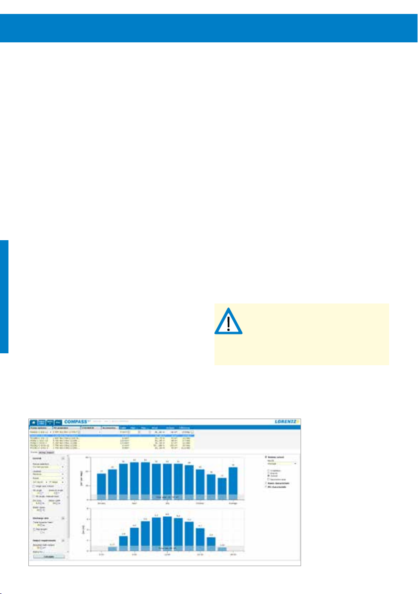
12 Schémas de conception et de dimensionnement d’un système de pompe12
Schémas de conception et de dimensionnement d’un système de pompe
6 Schémas de conception et de dimensionnement d’un système de pompe
6.1 Dimensionnement d’un système de pompe
Pour dimensionner et installer d’une manière professionnelle
un système de pompage d’eau, plusieurs variables
doivent être prises en compte selon le type de pompe et
l’application:
Hauteur statique – Hauteur verticale du niveau dynamique de l’eau jusqu’au plus haut point de livraison.
Hauteur d’aspiration – Hauteur verticale du niveau de
l’eau à l’entrée de la pompe à l’endroit où le niveau de l’eau
est au-dessous de l’entrée de la pompe.
Pertes de pression – Perte de pression de l’eau due à la
longueur du tuyau et au frottement causé par le matériau
du tuyau et les éléments ajoutés à la tuyauterie tels que
coudes, vannes.
Pour un pompage d’eau solaire, il est aussi nécessaire de
connaître le rayonnement local pour calculer la puissance
disponible chaque jour et l’effet sur le débit d’eau.
Pour gérer facilement et prendre en considération les
différentes variables, LORENTZ recommande vivement
de dimensionner des systèmes de pompe avec LORENTZ
COMPASS, le logiciel de planification des pompes solaires.
COMPASS est l’outil de LORENTZ pour concevoir,
planifier et spécifier les systèmes de pompes
solaires. Il peut être téléchargé par tous les partenaires
LORENTZ sur partnerNET.
COMPASS est un outil qui s’utilise sur PC permettant de
spécifier simplement les systèmes de pompes solaires en
temps réel. Il se base sur les données météorologiques de
la NASA et utilise des algorithmes précis pour les calculs
même les plus complexes.
En sélectionnant l’emplacement dans une liste de plus de
250000villes, en saisissant la hauteur manométrique et
le volume d’eau nécessaire par jour, le logiciel indiquera
automatiquement les systèmes de pompes adaptés et la
taille nécessaire du générateur PV.
Pour des situations plus complexes, COMPASS propose des
fonctionnalités telles que le calcul de la hauteur d’aspiration
ou de la perte de pression spécifique au type de tuyau.
REMARQUE – Toujours s’assurer que les
valeurs utilisées pour le dimensionnement
avec COMPASS correspondent bien aux
conditions sur site. Des paramètres
incorrects peuvent entraîner un rapport de
dimensionnement erroné.
Figure1: dimensionnement COMPASS
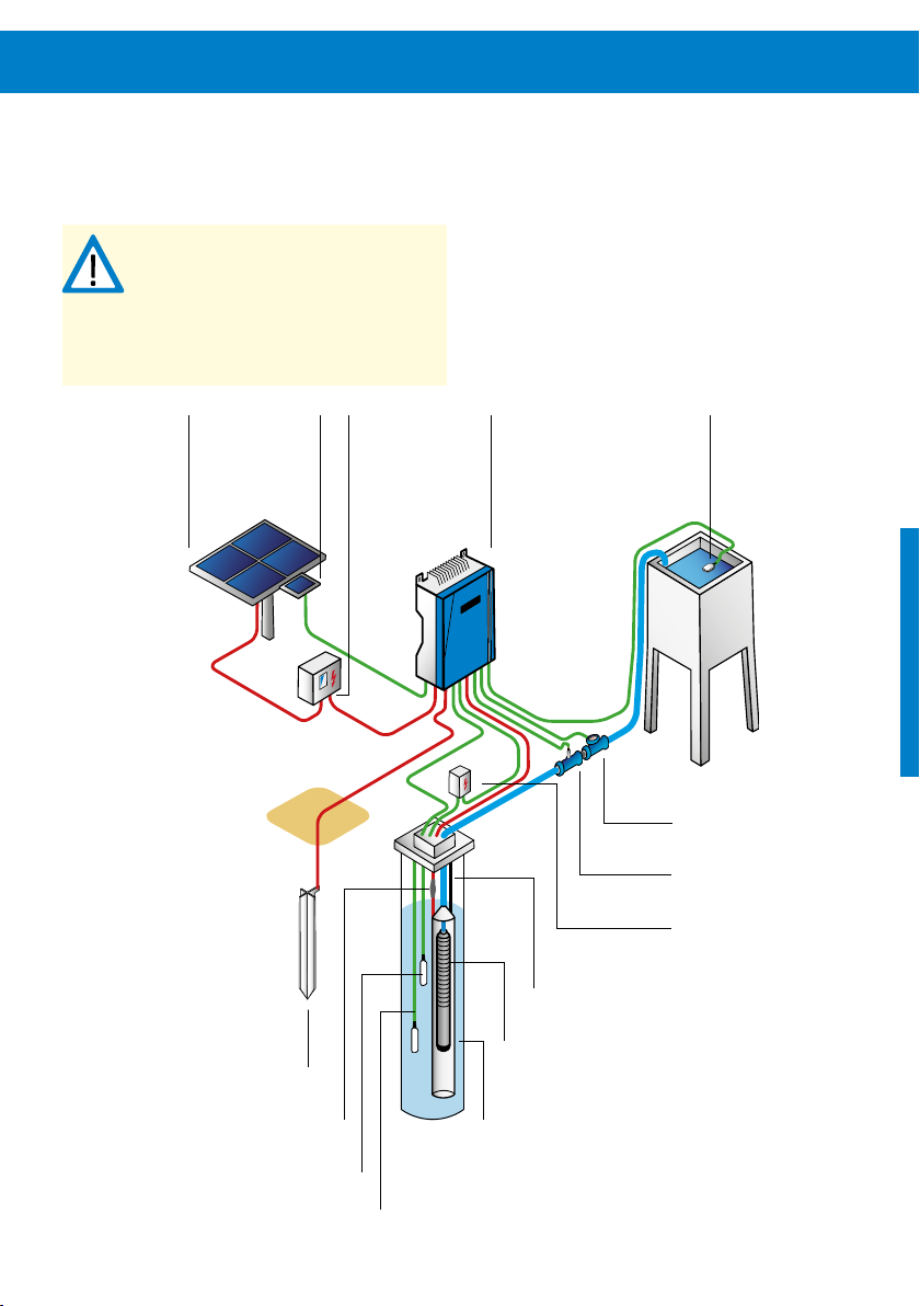
Schémas de conception et de dimensionnement d’un système de pompe
6.2 Conception du système: pompes immergées
AVERTISSEMENT – Ce schéma est un
organigramme type de système de pompe.
Il n’a pour objet que de permettre une
bonne compréhension du sujet. Pour
l’installation et le câblage du système,
lireet suivre les instructions détaillées
dans ce manuel.
13
Générateur
PV
Tige de mise à la terre
Module
SunSensor
Sectionneur
PV
Contrôleur
PS2
Filin de sécurité
Pompe immergée
Interrupteur
à flotteur
Compteur d’eau
Capteur de pression
Dispositif de protection contre
les surtensions
Kit d’épissurage
Sonde de puits
Capteur de niveau
Tube de décantation

14 Schémas de conception et de dimensionnement d’un système de pompe14
Schémas de conception et de dimensionnement d’un système de pompe
6.3 Conception du système: pompes de surface
AVERTISSEMENT – Ce schéma est un
organigramme type de système de pompe.
Il n’a pour objet que de permettre une
bonne compréhension du sujet. Pour
l’installation et le câblage du système,
lireet suivre les instructions détaillées
dans ce manuel.
Générateur
Dispositif de
protection contre
les surtensions
Interrupteur à flotteur
ou sonde de puits
PV
Module
SunSensor
Tige de mise
à la terre
Sectionneur
PV
Contrôleur
PS2
Détecteur d’eau
Filtre
Robinet à vanne
Interrupteur
àflotteur
Compteur d’eau
Vanne
Remplisseur
Capteur de pression
Pompe de surface
Clapet anti-retour
Cage de filtre
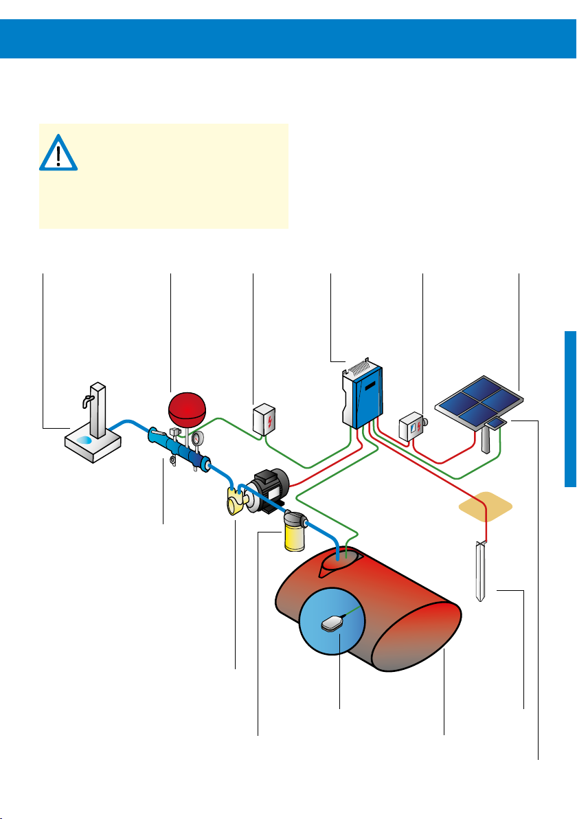
Schémas de conception et de dimensionnement d’un système de pompe
6.4
Conception du système: pompes Boost de surface
AVERTISSEMENT – Ce schéma est un
organigramme type de système de pompe.
Il n’a pour objet que de permettre une
bonne compréhension du sujet. Pour
l’installation et le câblage du système,
lireet suivre les instructions détaillées
dans ce manuel.
15
Robinet
d’eau
Réservoir
sous
pression
Kit d’installation
de PS Boost
Dispositif de
protection
contre les
surtensions
Pompe PS Boost
Contrôleur
PS2
Sectionneur
PV
Générateur
PV
Filtre en ligne
pour PS Boost
Interrupteur
à flotteur
Tige de mise
à la terre
Réservoir enterré
Module SunSensor
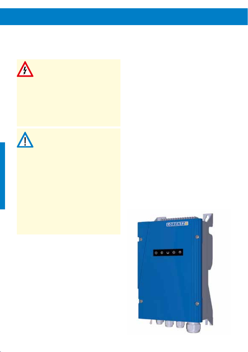
16 Installation du contrôleur
7 Installation du contrôleur
7.1 Généralités
ATTENTION – Tous les raccordements
électriques doivent être effectués par
desspécialistes qualifiés uniquement.
ATTENTION – Ne pas démonter le
contrôleur lorsqu’il est branché à
l’alimentation électrique! Avant toute
installation, maintenance ou inspection,
attendre au moins deux minutes après
avoir débranché le contrôleur de
l’alimentation électrique.
AVERTISSEMENT – Pour éviter des
démarrages à répétition de la pompe
dansdes conditions de luminosité
changeantes, le module SunSensor doit
être raccordé et configuré sur tous les
systèmes de pompage PS2-1800CS-F et
PS2-4000. Son fonctionnement sans
module SunSensor peut entraîner une
usure accrue ou un endommagement de
lapompe. Ce type d'endommagement
n'est pas couvert par la garantie.
AVERTISSEMENT – Ne jamais faire tourner
la pompe à sec. L’utilisation de la pompe
àsec endommagera cette dernière et
annulera la garantie. LORENTZ exige une
protection contre le fonctionnement à
secpour chaque système de pompe.
Pour plus d’informations sur les accessoires obligatoires
et leur installation, se reporter à «7.6.3 Câblage des
accessoires de la pompe» page27 et «9 Installation
des accessoires de lapompe» page57.
Le contrôleur est un déchet industriel qui doit être mis
au rebut en conséquence. Certains composants sont
susceptibles de produire des gaz nocifs et toxiques.
Un kit de prise est disponible séparément du contrôleur
encas d'utilisation de fiches mâles.
Figure2: contrôleur PS2
Sectionneur CC
Conduite électrique
Tout système de pompe solaire doit être équipé d’un
sectionneur CC correctement dimensionné. Le sectionneur
doit être installé entre le générateur PV et le contrôleur.
Ildoit satisfaire aux exigences suivantes:
valeur nominale minimale selon le «Tableau1:
puissance nominale minimale du sectionneur CC»
page17
courant continu nominal selon le courant maximum
dugénérateur PV CONNECTED ou supérieur
sectionneur adapté à du courant CC et non CA.
Un sectionneur PV, satisfaisant à toutes les exigences cidessus, est disponible auprès de LORENTZ.
AVERTISSEMENT – L’utilisation d’un
sectionneur correctement dimensionné
est une mesure de sécurité importante et
obligatoire pour l'installation professionnelle d’un système de pompage solaire.
Tableau1: puissance nominale minimale du sectionneur CC
Contrôleur Puissance nominale min.
dusectionneur CC
PS2-150 50VCC
Il est recommandé d’utiliser une conduite électrique. Nous
recommandons l’utilisation d’une conduite (tuyau) électrique
pour protéger le câblage extérieur des intempéries, des
activités humaines ou des dommages causés par des animaux. En l’absence d’une telle conduite, utiliser des câbles
de qualité élevée pour usage extérieur. Utiliser également
des presse-étoupes d’étanchéité anti-traction au niveau de
l’entrée des câbles dans la boîte de jonction.
Section
Pour les câbles de signaux, la section minimum est de
1,5mm2 (AWG16). Pour les câbles d'alimentation, la
section minimum est de 2,5mm2 (AWG14). Comparer
ses sections de câble aux rapports de dimensionnement
de LORENTZCOMPASS. Les câbles doivent être blindés de
façon à répondre aux exigences en matière de compatibilité
électromagnétique.
Pour un usage à l'extérieur, il est recommandé d'employer
des câbles répondant aux exigences de la norme 60245
IEC66. Pour un usage en intérieur, le type de câble recommandé est défini dans la norme 60245 IEC 57. Le monteur
devra tenir compte des spécificités, réglementations et codes
de bonne pratique locaux et employer un câble qui répond
à ces exigences.
PS2-200 100VCC
PS2-600 150VCC
PS2-1800 200VCC
PS2-4000 375VCC

18 Installation du contrôleur
7.2 Éléments du contrôleur
Interrupteur Arrêt/Marche (Power On/Off) –
L’interrupteur d’arrêt/marche est utilisé pour démarrer ou
arrêter le système et comme interrupteur de réinitialisation. Il ne fonctionne pas comme un sectionneur.
Indicateurs lumineux – Les cinq LED sur le devant
indiquent différentes situations de fonctionnement. Pour
en avoir une explication détaillée, se reporter au chapitre
«10 Fonctionnement de la pompe» page64.
Tableau2: données techniques du contrôleur PS2
Modèle Moteur de
PS2-150
Boost
PS2-150 0,3 ECDRIVE 150-C 50 17 22
pompe:
puissance
nominale
[kW] [V] [V] [A]
0,3 ECDRIVE 150-Boost 50 17 22
Moteur de pompe
apparenté
7.3 Données techniques du contrôleur
Se reporter au «Tableau2: données techniques du
contrôleur PS2» page18 pour une présentation des plus
importantes caractéristiques techniques du contrôleur PS.
Tension
d’entrée c.c.
max.
Vmp minimum
recommandée
Courant de
sortie max.
PS2-200 0,3 ECDRIVE 200-HR 100 34 11
ECDRIVE 600-HR
PS2-600 0,7
PS2-1800 1,7
PS2-4000 4,0
ECDRIVE 600-C
ECDRIVE 600-CS-F
ECDRIVE 1800-HR
ECDRIVE 1800-C
ECDRIVE 1800-CS-F
ECDRIVE 4000-HR
ECDRIVE 4000-C
ECDRIVE 4000-CS-F
150 68 13
200 102 14
375 238 14

7.4 Mise en place du contrôleur
Le contrôleur doit rester protégé de l’eau, de l’humidité et
des animaux. Son boîtier doit donc toujours être étanche.
Positionner le contrôleur dans un endroit sec et suffisamment ventilé.
Placer le contrôleur à proximité du panneau solaire, pas
de la pompe, pour réduire le risque de dommages dus
à la foudre. Les circuits d’entrée du contrôleur sont plus
sensibles aux surtensions que ceux de sortie. Il est ainsi
plussûr de limiter la longueur du câblage d’entrée.
Les équipements électroniques présentent une plus grande
fiabilité lorsqu’ils sont protégés contre la chaleur. Placer
le contrôleur à l’ombre du soleil de midi. La partie sous
le générateur PV constitue un emplacement idéal. En
l’absence d’ombre, boulonner une plaque de métal derrière
le contrôleur et la plier de sorte à former un écran au-dessus
de celui-ci. Cette protection est particulièrement importante
dans les zones climatiques très chaudes. Une température
excessive est susceptible d’activer la protection thermique
du contrôleur, provoquant une réduction de la consommation électrique ou l’arrêt du contrôleur. Le boîtier du
contrôleur peut atteindre des températures élevées lorsqu’il
fonctionne à des températures ambiantes importantes.
C’estnormal et cela ne réduira pas la durée de vie attendue
du contrôleur ou de ses composants.
7.5 Exigences de montage, d’espace et de
ventilation
Les contrôleurs PS2 peuvent être montés côte à côte.
Pour la mise à terre du couvercle frontal, les vis du couvercle
doivent être serrés avec un couple de serrage minimal de
2 Nm.
Les contrôleurs PS2 ne disposent pas de ventilateur; ils sont
refroidis par convection d’air. Il est vivement conseillé de ne
pas installer le contrôleur dans un coffret supplémentaire.
Si un coffret supplémentaire est nécessaire, un débit d’air
vertical suffisant (de bas en haut) doit être garanti pour que
le refroidissement soit suffisant.
Les contrôleurs PS2 ont un système de fixation par des
trous de serrures pour simplifier le montage sur les surfaces
appropriées. Pour le montage aux poteaux et aux structures
similaires le PS2 est compatible avec les accessoires de
supports de fixations LORENTZ pour un maximum de
commodité.
Lorsque vous fixez le contrôleur PS2 avec les accessoires de
supports de fixation LORENTZ, serrez les vis diagonalement
et uniformément.
AVERTISSEMENT – ne serrez pas trop les
vis de montage au boîtier PS2 quand vous
utilisez les accessoires de supports de
fixation pour éviter d’endommager le
boîtier du contrôleur PS2.
AVERTISSEMENT – lorsque vous utilisez les
supports de fixation, pour les systèmes de
haute performance et/ou dans les régions
avec des températures ambiante élevées,
il faut installer une plaque arrière entre le
contrôleur et les supports de fixation pour
empêcher l’effet d’entonnoir des ailettes
de refroidissement. Le fonctionnement
sans plaque arrière peut mener à un
refroidissement insuffisant qui entraînera
une performance réduite.
Pour connaître les dimensions du contrôleur, se reporter au
«Tableau3: dimensions d’installation du contrôleur PS2»
page20.

20 Installation du contrôleur
Figure3: dimensions d’installation du contrôleur PS2
L3
H1
H2
H3
P1L2
L1
Tableau3: dimensions d’installation du contrôleur PS2
Dimensions en mm [in]
Poids en kg [lbs]L1 L2 L3 H1 H2 H3 P1
207 170 164 352 333 300 124 4,5
[8,15] [6,69] [6,46] [13,86] [13,11] [11,81] [4,88] [9,9]

7.6 Câblage du contrôleur
ATTENTION – Tous les raccordements
électriques doivent être effectués par des
spécialistes qualifiés uniquement. Une
manipulation effectuée par une personne
non qualifiée peut entraîner un choc, des
brûlures ou la mort.
ATTENTION – Haute tension.
Ne jamais travailler sur un système sous
tension ou dans les deux minutes suivant
son débranchement afin d’éviter tout
chocélectrique.
Avant de commencer à travailler sur le système électrique,
s’assurer que tous les composants sont débranchés de la
source électrique. Ne pas travailler sur des composants
lorsqu’ils sont sous tension et attendre deux minutes après
les avoir mis hors tension. Le contrôleur a besoin de temps
pour se décharger.
Mettre le système sous tension uniquement lorsque toutes
les tâches sont terminées.
AVERTISSEMENT – Le contrôleur doit
uniquement être mis sous tension après
uncâblage correct, à défaut de quoi il
risquerait d’être endommagé.
AVERTISSEMENT – Ne pas installer de
sectionneur sur les câbles d’alimentation
entre le moteur et le contrôleur de la
pompe. Le fait de brancher les câbles du
moteur à un contrôleur sous tension peut
entraîner des dommages irréparables.
Cetype d'endommagement n'est pas
couvert par la garantie.
AVERTISSEMENT – Systèmes sans batterie
uniquement – Ne pas raccorder d’équipement électrique supplémentaire (hors
contrôleur de pompe LORENTZ) au
générateur PV. L’ajout d’un chargeur de
batteries, d’un contrôleur de suivi de
trajectoire, d’un chargeur de clôture
électrique ou de tout autre appareil
parallèlement aux systèmes LORENTZPS2
est de nature à interférer avec le
fonctionnement du contrôleur et empêcher
son bon fonctionnement.
AVERTISSEMENT – Mesurer la tension
avant de relier l’alimentation au contrôleur. La tension (circuit ouvert) ne doit pas
dépasser l’entrée c.c. max. (se reporter
au«Tableau2: données techniques du
contrôleur PS2» page18).
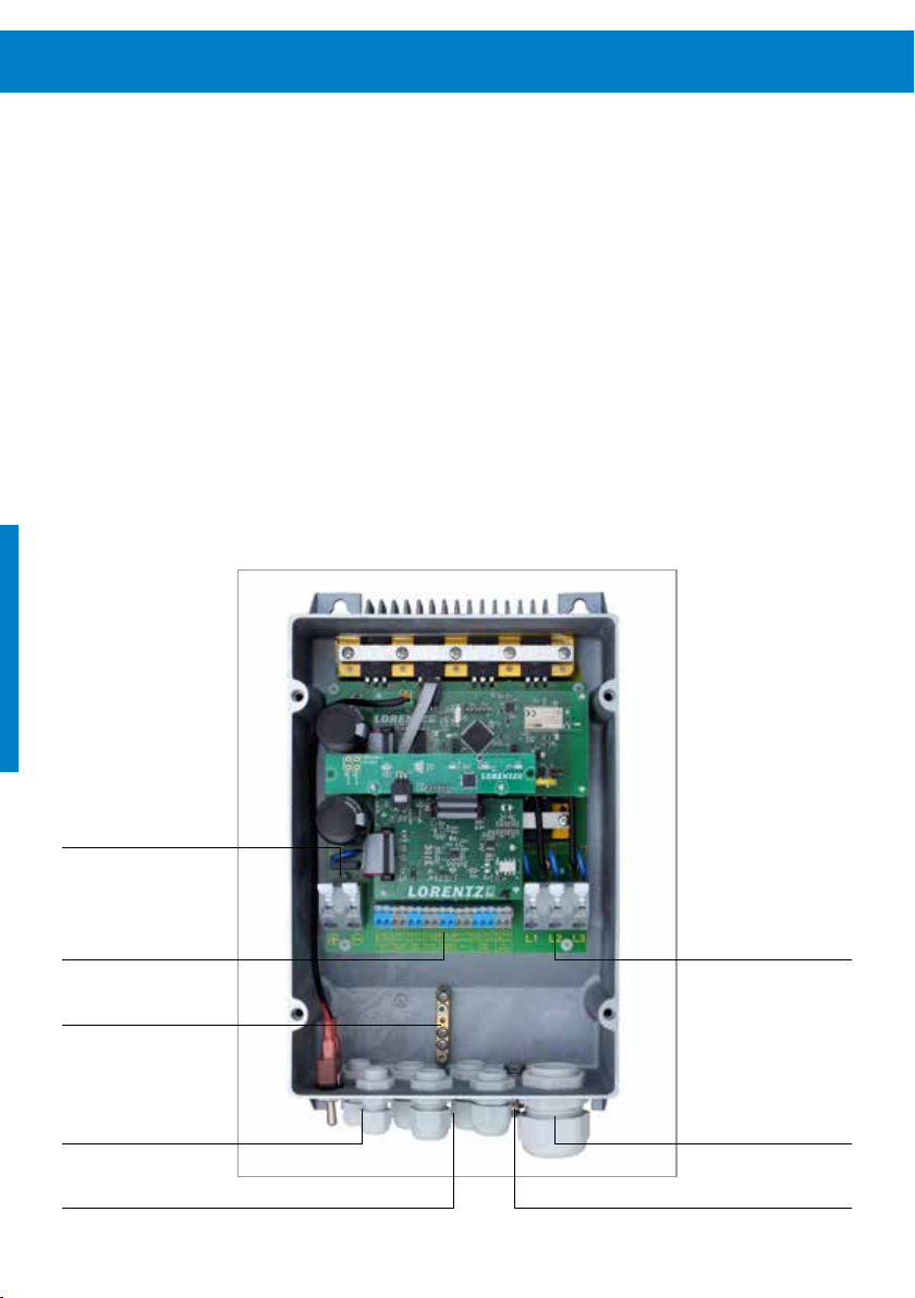
22 Installation du contrôleur
7.6.1 Description des bornes
Le boîtier s'ouvre en dévissant les quatre vis situées sur son
capot frontal. Les bornes sont facilement accessibles une
fois le capot frontal retiré.
Pour les bornes «Power in» et «Motor», ouvrez le
serre-câbles, y insérer le câble et remettre les serre-câbles
en place pour les verrouiller. Procéder avec précaution et
maintenir fermement les leviers des serre-câbles, car les
bornes comportent de puissants ressorts. Se reporter à
«Figure6: bornes «Power in» et «Motor»» page23.
La longueur de dénudage des câbles pour ces bornes est
de12-13mm (0,5in).
Figure4: vue du contrôleur PS2 ouvert
Solaire en +–
Pour les bornes 1 à 17, ouvrir la borne en repoussant le
levier du serre-câbles avec un tournevis, y insérer le câble
puis relâcher le levier pour bloquer le câble. Se reporter à
«Figure7: bornes 1 – 17» page23. La longueur de dénudage des câbles pour ces bornes est de 5-6mm (0,2in).
Bornes 1 – 17
Terre
Presse-étoupe des senseurs
Pompe L1 L2 L3
Presse-étoupe du moteurPresse-étoupe «Solar in»
Boulon de mise à la terre extérieur
 Loading...