

Page 1
LORD USERMANUAL
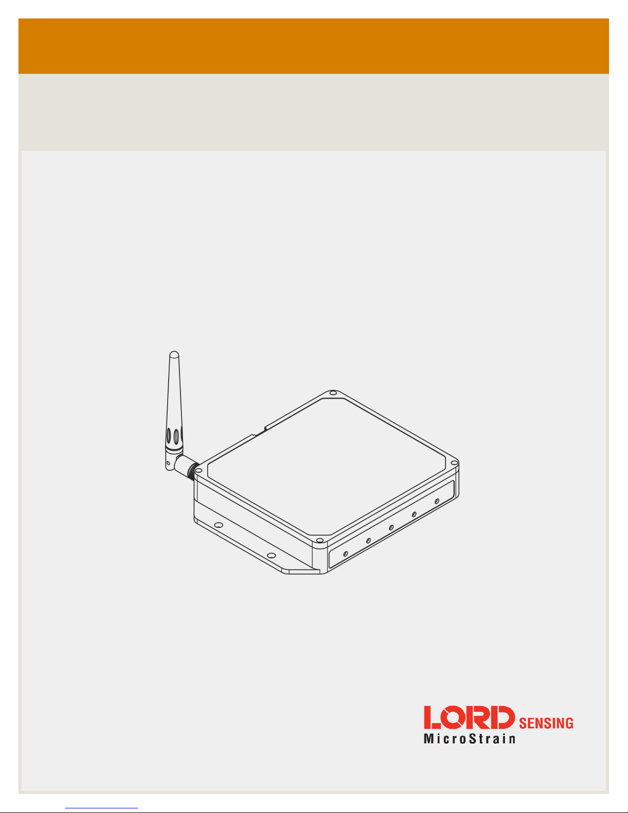
WSDA®-2000
Wireless Sensor Data Aggregator
Page 2

LORD SensingSystems
459HurricaneLane
Suite102
Williston,VT 05495
UnitedStatesof America
Phone: 802-862-6629
Fax: 802-863-4093
9:00AM to 5:00PM (EasternTimeUS& Canada)
http://www.microstrain.com
Document 8500-0090 Revision A
Subjecttochange without notice.
Page 3
WSDA®-2000 User Manual
Table of Contents
1. Wireless Sensor Network Overview
2. Gateway Overview
2.1 GatewayComponents
2.2 GatewayInterface
3. System Operation
3.1 Software Installation
3.2 System Connections
3.3 Gateway Operation
3.4 Gateway Communication
3.5 Gateway Settings
3.5.1 Access WSDA Control Panel 14
3.5.2 Change Transmit Power 16
3.5.3 Change Frequency 16
6
7
8
9
10
10
11
12
12
14
4. Gateway Menu Navigation
4.1 Gateway Information
4.1.1 About the Gateway 18
4.1.2 Node List 20
4.2 Data Options Menu
4.2.1 CAN J1939 Output 22
4.2.2 Data Alias Definitions 29
4.2.3 SensorCloud™ Upload Filter 31
4.2.4 WSDA Data Downloader Calibration Coefficients 32
4.2.5 Clear Stored Data 34
4.3 Gateway Tools Menu
4.3.1 Diagnostics 35
4.3.2 Configuration 36
18
18
21
34
Page 4
WSDA®-2000 User Manual
4.3.3 Time Options 39
4.3.4 Reboot 41
4.3.5 OperatingSystem (OS) Upgrade 42
4.3.6 Change Password 43
5. Remote Connectivity
6. Using the Beacon
6.1 System Bandwidth in Synchronized Sampling
6.2 Synchronized Sampling with Multiple Gateways
7. Sensor Node Access
7.1 Connect to Nodes
7.1.1 Automatic Node Discovery on Same Frequency 49
7.1.2 Automatic Node Discovery on Different Frequency 49
7.1.3 Manually Add Node 51
7.2 Configure Node
7.3 Configure and Start Sampling
8. Viewing Data
8.1 SensorCloud
44
47
48
48
49
49
53
53
58
58
8.1.1 Navigating Menus 58
8.2 SensorConnect
8.2.1 Using Dashboards and Widgets 61
8.2.2 Navigating Graphs 62
8.2.3 Widgets Options 62
8.2.4 Time Series Widget Menu 63
8.2.5 Exporting Data Files 63
8.3 Using the Data Downloader
9. Gateway Installation
9.1 Installation Recommendations
61
64
68
68
Page 5
WSDA®-2000 User Manual
9.1.1 Range Test 70
9.2 Multi-port Connector Interface
10. Troubleshooting
10.1 Troubleshooting Guide
10.2 Communications Ports inWindows®
11. Parts and Configurations
11.1 Standard Models
11.2 Wireless System Equipment
12. Specifications
12.1 Physical Specification
12.2 Operating Specifications
12.3 Radio Specifications
13. Safety Information
13.1 Disposal and Recycling
71
72
72
76
79
79
79
81
81
82
84
85
85
14. References
14.1 Related Documents
15. Glossary
86
86
87
Page 6

WSDA®-2000 User Manual
1. Wireless Sensor Network Overview
The LORD Sensing Wireless Sensor Network is a high-speed, scalable, sensor data acquisition and
sensor networking system. Each system consists of wireless sensor interface nodes, a data collection
gateway, and full-featured user software platforms based on the LORD Sensing Lossless Extended
Range Synchronized (LXRS) and LXRS+ data communications protocols. Bi- directional wireless
communication between the node and gateway enables sensor data collection and configuration.
Gateways can be connected locally to a host computer or remotely via local and mobile networks. Some
gateways also feature analog outputs for porting sensor data directly to stand-alone data acquisition
equipment.
The selection of available nodes allows interface with many types of sensors, including accelerometers,
strain gauges, pressure transducers, load cells, torque and vibration sensors, magnetometers, 4 to 20 mA
sensors, thermocouples, RTD sensors, soil moisture and humidity sensors, inclinometers, and orientation
and displacement sensors. Some nodes come with integrated sensing devices such as accelerometers.
System sampling capabilities include lossless synchronized sampling, continuous and periodic burst
sampling, and data logging. A single gateway can coordinate many nodes of any type, and multiple
gateways can be managed from one computer with the SensorConnect™ and SensorCloud™ software
platforms. Integration to customer systems can be accomplished using OEM versions of the sensor nodes
and leveraging the LORD Sensing data communications protocol.
Common wireless applications of LORD Sensing Sensing Systems are strain sensor measurement,
accelerometer platforms, vibration monitoring, energy monitoring, environmental monitoring, and
temperature monitoring.
6
Page 7

WSDA®-2000 User Manual
2. Gateway Overview
The WSDA -2000 is a data acquisition gateway designed to configure, co-ordinate, and collect sensor
data from LORD Sensing wireless sensor nodes. The gateway supports all data acquisition sessions
between wireless nodes and host computers including: continuous sampling, burst sampling, and
datalogging. The gateway also facilitates precision sampling synchronization between sensor nodes by
transmitting a continuous, system-wide timing reference known as the beacon. Communication between
the nodes and gateway is wireless and uses the LORD Sensing LXRS and LXRS+ data communications
protocols.
The WSDA-2000 utilizes Ethernet and USB interfaces to transfer data from the wireless nodes to a host
computer for viewing, analysis, and storage. It also provides a CAN data ouput.
7
Figure 1 - WSDA-2000
Page 8
WSDA®-2000 User Manual
2.1 GatewayComponents
The WSDA-2000 can be purchased individually or in a starter kit. The kit includes everything required
to operate the WSDA-2000 including a removable external antenna, a power supply, and cables for
interfacing with the host computer or network. For a complete list of available configurations,
accessories, additional system products, and ordering information
page 79
.
see Parts and Configurations on
Ite-
m
A
B
C
D
E
--
WSDA-2000
Antenna
Ethernet cable, 10 ft
Power supply & plug adapter kit
USB cable
SensorConnect download at:
http://www.microstrain.com/software
Description
Figure 2 - Starter Kit Components
8
Page 9
WSDA®-2000 User Manual
2.2 GatewayInterface
The WSDA-2000 interfaces include a power input jack , a power on/off switch, an antenna connector
for attaching the gateway antenna, an Ethernet jack, a multi-use (multi-port) connector, and a USB
port.The indicators on the WSDA-2000 include several device and data status indicators, and a power
indicator. The following table describes basic indicator behavior.For a complete list of all indicator
behaviors
see Device Status Indicators on page 1
.
Figure 3 - Ports and Indicators
Indicator Behavior Node Status
1. PO WER
2. W SDA
3. DATA
4. ACT
5. CLOUD
OFF Gateway is off
ON green Gateway is on
ON green Fully booted & idle
Flashing blue & green
Flashing green Receiving wireless data
Flashing blue Sync sampling beacon enabled
Flashing red
-- (future use)
Flashing blue Uploading data to SensorCloud™
ON green Web upload successful
ON red Web upload error
Sampling and porting data through
SensorConnect™
WARNING: another gateway beacon
isdetected on the same fr equency
Table 1 - Basic Indicator Behaviors
9
Page 10

WSDA®-2000 User Manual
3. System Operation
The WSDA-2000 is an advanced gateway that aggregates LORD Sensing wireless data and interfaces
LORD Sensing wireless networks to SensorCloud™ and data acquisition computers.
LORD Sensing's SensorConnect software program is available for data acquisition from the wireless
sensor network. This is a PC- based software used for configuring gateways and nodes, selecting
sampling modes and parameters, initializing data acquisition, and viewing and saving data.
3.1 Software Installation
Install the SensorConnect software on the host computer before connecting any hardware. Access the
free software download on the LORD Sensing website at:
http://www.microstrain.com/software
SensorCloud is an optional data collection, visualization, analysis, and remote management tool. It is
based on cloud computing technology and is accessed directly from a web connection. For more
information go to: http://www.sensorcloud.com/.
10
Page 11

WSDA®-2000 User Manual
3.2 System Connections
To acquire sensor data the following components are needed: a LORD Sensing wireless sensor node,
a LORD Sensing data gateway, and a host computer with access to the data acquisition software.
The sensor, node, gateway, and software selection are application-dependent, but the basic interfaces
are the same. The WSDA-2000 gateway utilizes Ethernet communications and can be used with
SensorConnect and SensorCloud™, although system configuration is completed using
SensorConnect. For a connections overview using the WSDA - 2000 refer to
Connections
.
Figure 4 - System
11
Figure 4 - System Connections
Page 12

WSDA®-2000 User Manual
3.3 Gateway Operation
The default configuration of Ethernet gateways is for DHCP network connectivity. If no
DHCP network is available, the USB port can be used for most operations, including device
configuration, local data acquisition, and to access the network configuration menu (WSDA
Control Panel). SensorConnect detects USB devices automatically and adds them to the
Deviceslist.
The Ethernet gateway has three primary operating sequences including gateway configuration, node
configuration, and data acquisition, viewing and analysis.
3.4 Gateway Communication
a. Power is applied to the gateway through the power jack on the back of the WSDA-2000. The
Ethernet jack is connected to the network using a CAT5 or better Ethernet cable.
NOTE
b. Open the SensorConnect™ software and select Add Device
c. Select the gateway and confirm the IP address shows in the IP Address field. The IP address can
be entered manually in the IP Address field above the Discovered Gateways section. If the
gateway does not appear, confirm that the host computer and the gateway are connected to the
same Ethernet network.
Figure 5 - Adding A Device
d. Select the green Add Device button.
e. The gateway will appear in the Controller window.
12
Page 13

WSDA®-2000 User Manual
Figure 6 - Gateway Communication
13
Page 14

WSDA®-2000 User Manual
3.5 Gateway Settings
3.5.1 Access WSDA Control Panel
The WSDA Control Panel menu provides access to gateway network settings, time synchronization
options, CAN output configuration, and more. To view the WSDA Control Panel, from the Devices
window, highlight the base station and select the WSDA Control Panel tile.
Figure 7 - Control Panel Access
Log in to the gateway Control Panel with the default credentials:
l Login: wsda
l Password: wsda
A navigation panel on the left shows three menu categories: General, Data, and Tools.
14
Page 15

WSDA®-2000 User Manual
Figure 8 - Control Panel Menus
a. General - This category includes menu selections for information about the gateway's iden-
tity and time settings (About) and the sensor nodes it currently has data for in memory
(Node List).
b. Data - This category includes menu selections that allow users to set which node and chan-
nel data is uploaded to SensorCloud™ (Upload Filter), set which data is pushed out the
CAN J1939 port (J1939), apply calibration coefficients to data downloaded from the gateway internal memory (Calibration), and clear data from the device internal memory (Clear
Data).
c. Tools - This category includes menu selections for troubleshooting the gateway (Dia-
gnostics); configuring communication settings, enabling and disabling operating
sequences, changing the node synchronization beacon state, and changing the gateway
radio frequency (Configuration); configuring system time (Time Options); rebooting the gateway (Reboot); updating the operating system (OS Upgrade); and changing the Control
Panel log-in (Change Password).
15
Page 16

WSDA®-2000 User Manual
3.5.2 Change Transmit Power
From the Base Station, select Configure > Transmit Power for a drop down menu of five power options
ranging from 0 dBm to 20 dBm.
Figure 9 - Transmit Power Setting
3.5.3 Change Frequency
There are 16 available frequency channels between 2.405 and 2.480 GHz. Wireless nodes and the
gateway must be on the same frequency channel to communicate.
To move the gateway to a different frequency, select Base Station and then the Change Frequency
tile. To move the node to the same frequency, select the Nodes on Other Frequencies tile after the
gateway has been changed.
16
Figure 10 - Gateway Frequency
Page 17
WSDA®-2000 User Manual
Setting the transmit frequency using SensorConnect is temporary for Ethernet gateways and
will revert back to the frequency setting selected in the gateway Control Panel when the
gateway is powered off or rebooted (see Gateway Settings on page 14 for how to change the
frequency setting in Control Panel)
NOTE
17
Page 18
WSDA®-2000 User Manual
4. Gateway Menu Navigation
4.1 Gateway Information
The General category provides information about the gateway identity, the wireless nodes it serves,
and its current time settings. These are informational only, and no user adjustments may be made in
these menus.
Table 2 - General Menus
Menu Description
About
Node List
Time Settings
provides a summary of the menus under the General category.
Provides information about the gateway identity
Displays a list of wireless nodes for which the gateway is currently
storing data
Provides time-related information
Table 2 - General Menus
4.1.1 About the Gateway
The About menu provides information about the gateway. Each item is defined below.
Figure 11 - About Menu
Device Name: an alias given to the WSDA - 2000 so that it is more easily recognized in Live
Connect. By default, the device name is not assigned, and Live Connect will use the device serial
number as an identifier. The device name can be changed in the Tool > Configuration menu (
Configuration on page 36
18
see
).
Page 19

WSDA®-2000 User Manual
Serial Number: an alpha-numeric identifier embedded in the WSDA-2000 hardware. The serial
number is assigned when the gateway is manufactured.
MAC Address: an alpha-numeric identifier embedded in the network card of the WSDA-2000
hardware. A MAC (Media Access Control) Address is a unique identifier assigned to all Ethernet
devices to manage communications on the network. The MAC address is assigned when the
gateway is manufactured.
Model Number: an alpha-numeric identifier used to identify the gateway type. The model number is
assigned when the gateway is manufactured.
OS Version: a numeric identifier used to identify the WSDA-2000 OS (Operating System) Version.
The OS is the on-board software that operates the WSDA-2000. All gateways are shipped with the
current OS version. As new features are added, OS updates are available from LORD Sensing
Technical Support (
> OS Upgrade menu (
see Technical Support on page 78
) and installed by the user through the Tools
see OperatingSystem (OS) Upgrade on page 42
).
Flash Card Utilization: the amount of memory currently consumed by data in the gateway internal
memory, and the total memory capacity. Data received from sensor nodes is stored here. When
capacity is reached, the flash card will begin overwriting data on a first-in, first-out basis (older data
is overwritten first).
Connection Type: the type of Ethernet connection the gateway is currently configured for - DHCP
or Static IP. This option and other settings can be changed in the Tools > Configuration menu (
Configuration on page 36
).
see
System Time: the current UTC time on-board the WSDA-2000 system clock. UTC (Coordinated
Universal Time) is the time standard by which the world regulates clocks and time. The system clock
is normally updated from internet time servers every 12 hours. For a more detailed discussion of the
system and real time clocks
see Time Options on page 39
.
Synchronization Status: the WSDA- 2000 is considered to be Synchronized if it has successfully
synchronized to one of its enabled time sources since it was booted, and before any periodic
synchronization has expired. Otherwise is considered to be Not Synchronized. For a more detailed
discussion of the system and real time clocks
see Time Options on page 39
.
Last Synchronized Time: the most recent time when the gateway was synchronized to a time
source
Last Synchronized Source: the source from which the most recent time synchronization occurred
19
Page 20

WSDA®-2000 User Manual
System Up-time: the elapsed time since the gateway was last powered on and booted up. The
system up-time will be zeroed when the gateway power is cycled or it is rebooted from the Tools >
Reboot menu.
System Resets: the number of times the gateway has been reset. System Resets will be
incremented when the gateway power is cycled or it is rebooted from the Tools > Reboot menu.
System Resets are written to non-volatile memory and is preserved through power outages.
4.1.2 Node List
The node list displays all the wireless nodes that have data currently stored in the gateway memory.
The node address is shown along with the sensor channels that were configured to transmit data to
the gateway, the relative timestamp (time since the node sent its first data to the gateway), and the
last timestamp (the time of the most recent node data received by the gateway).
20
Figure 12 - Node List
Page 21
WSDA®-2000 User Manual
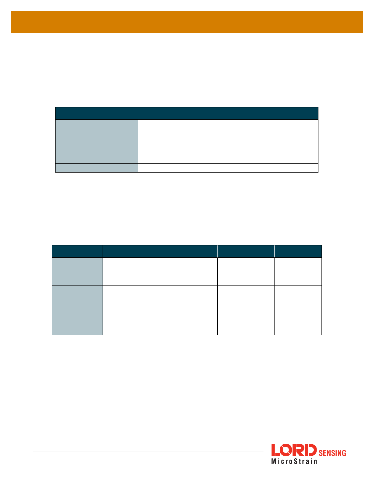
4.2 Data Options Menu
The Data category provides data handling options such as selecting which data is sent to the
CANJ1939 bus, uploaded to SensorCloud™, and downloaded to a host computer. Data can also be
cleared from the WSDA - 2000 internal memory.
menus under the Data category.
Menu Description
J1939
Upload Filter
Calibration
Clear Data
Table 3 - Data Menus
Enable and select what sensor data is sent out in CANJ1939 format
and what method is used
Select which sensor nodes and channels are uploaded to
SensorCloud™
Apply calibration conversions values and select
measurement display units before downloading saved data
Erase data from the gateway flash memory
provides a summary of the
Table 3 - Data Menus
Nomenclature for node address, channel assignments, and other data are used in some of the Data
menus.
assignments. Node information found in the Node List are also annotated this way (
page 20
Table 4 - Data Nomenclature
describes the required naming conventions for these
).
Field Description Nomenclature Examples
Node address assigned when the node is
Address
Channel
Channel List
Payload
manufactured. Provided with the node
and displayed in SensorConnect when
connected
Data and packet value aliases such as for
node address, node channel number,
radio strength, and protocol values. Channel number assignment is handled in
SensorConnect. All other aliases are
fixed (
see Data Alias Definitions on page
29
).
decimal number 31463
lower case text
followed by a number. In a channel
list multiple values
are separated by a
comma or space
ch1
ch1,ch2,ch5,
bin1, rssi
ch2 angleid
see Node List on
Table 4 - Data Nomenclature
21
Page 22

WSDA®-2000 User Manual
4.2.1 CAN J1939 Output
In addition to saving locally or uploading through an Ethernet connection, data acquired from sensor
nodes can also be pushed onto a CAN J1939 bus for reactive command and control of external
devices and other applications. By default the output is disabled. Enable the output in the Tools >
Configuration menu
The J1939 menu includes CAN communication settings (J1939 Bus Configuration) and output
messages configuration (J1939 Broadcast Message Configuration) (
page 22
).
see Configuration on page 36
.
see CAN J1939 Menu on
The bus configuration settings include the Bit Rate, data Source, and data Destination.
The bit rate is set as required by the host CAN bus that the gateway is integrated with. The default is
250 kilobits per second (kbps), which is typical for most applications.
22
Figure 13 - CAN J1939 Menu
Page 23
WSDA®-2000 User Manual
The wireless data transmit rate (between the node and the gateway) directly impacts
the data bandwidth on the CAN bus. If the aggregate transmit rate of the wireless
network (combined bandwidth use of active nodes) is high enough and there are other
devices (besides the gateway) on the CANbus, the bus may be overwhelmed,
resulting in lost data. The gateway settings provide no limitations to how much
data is pushed onto the bus. If there are no other devices on the CAN bus, this is
not an issue, however it is up to the user to determine the amount of data the bus can
handle from each device. Increasing the CAN bus bit rateand adjusting sensor
sampling settings, such as reducing sample rates and period, can be used to alleviate
CANbus bandwidth limitations. Using the broadcast message data distribution method
and reducingthe sensor data that is sent to the bus can also be effective.
The Source setting refers to where the data is coming from, as in, how the WSDA-2000 will be
recognized and addressed on the CAN bus (
l By setting the source to Name, the gateway will acquire an address dynamically by
requesting it in sequential order, within the dynamic address range, until no other device
contests it (
NOTE
Figure 14 - Data Source Setting
Table 5 - WSDA-2000 J1939 Values
).
).
l By setting the source to Address, the user can assign a static address within the gateway
address range (
Table 5 - WSDA-2000 J1939 Values
). This address is typed in the field
next to the Source field, in place of the name.
Figure 14 - Data Source Setting
23
Page 24
WSDA®-2000 User Manual
With either setting, the gateway will be identified by the name assigned to it when manufactured
(which is displayed to the right of the Source selection menu). This name provides the host CAN
bus with information about the device that determines its data priority relative to other devices on the
bus (
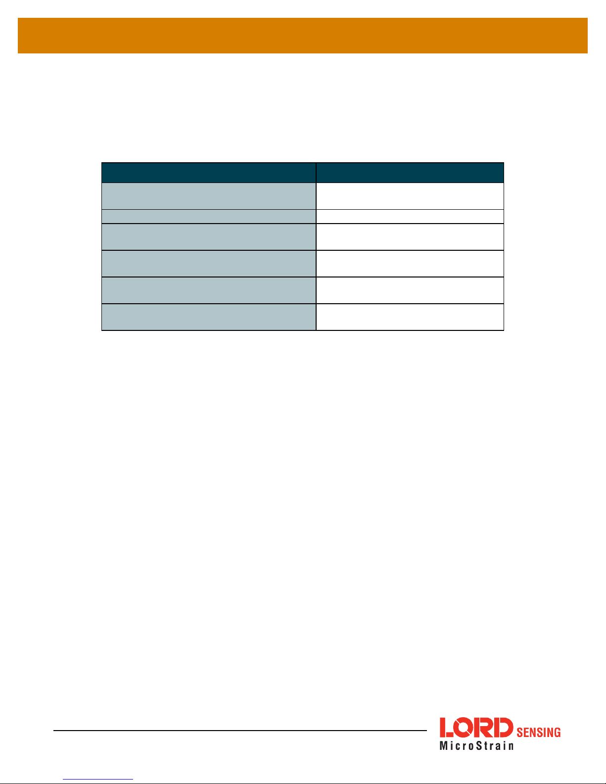
Table 5 - WSDA-2000 J1939 Values
).
Description Range
J1939 name
(assigned when manufactured)
J1939 bus bit rate (user setting)
J1939 dynamic address range
(Source set to Name)
J1939 static address range
(Source set to Address)
Destination specific PGN
(Destination set to Name or Address)
Broadcast message PGN range
(Destination set to None)
0x8000FF0047200000
250 kbps (default), 500 kbps, 1 Mbps
0x80 to 0xCF
0x00 to 0xFF
0xEF00
0xFF00 to 0xFFFF
Table 5 - WSDA-2000 J1939 Values
The Destination setting refers to how the sensor data will be received on the CAN J1939 bus and
the desired method of sensor data distribution. Sensor data can be pushed onto the bus either by
sending all of the sensor messages to one CAN device (destination-specific), or by broadcasting
user-selected messages onto the entire CAN bus (broadcast).
l Destination-specific messages can be sent to either a CAN device Address or device
Name. Set Destination to either Name or Address and then type in the device name or
address (as applicable) into the Source field in hexadecimal format. These are the only
setting required for this type of messaging.
l For broadcast messages, the Destination is set to None and the user-designated
messages are constructed either in J1939 Broadcast Message Configuration window or in
a text file that is uploaded from the menu.
To change any of the settings, select from the drop down menus for each one and then select the
Save button to save the selected settings (
Broadcast Message Configuration
The J1939 Broadcast Message Configuration section provides a form for the user to define J1939
broadcast messages. The user must specify a unique identifier for each packet called the
Parameter Group Name (PGN). This value is up to the user to select but must be within the range
24
Figure 14 - Data Source Setting
).
Page 25
WSDA®-2000 User Manual
allowed (0xFF00 through 0xFFFF). Additionally, the user must also define which data values the
WSDA should forward onto the bus for each given PGN and under which conditions.
To define which data to send for a given PGN, the user must specify the address of the wireless
node producing the data and the name of each data stream from that node which should be
forwarded onto the bus. If the user only wants to forward data when a certain condition is met, the
user may specify which data stream to use for the conditional (e.g. ch1), what condition to use (e.g.
is greater than), and the value for the comparison (e.g. 4.0). Otherwise, these fields may be left
blank. The wireless node must also be capable of producing the specified information and
configured to do so.
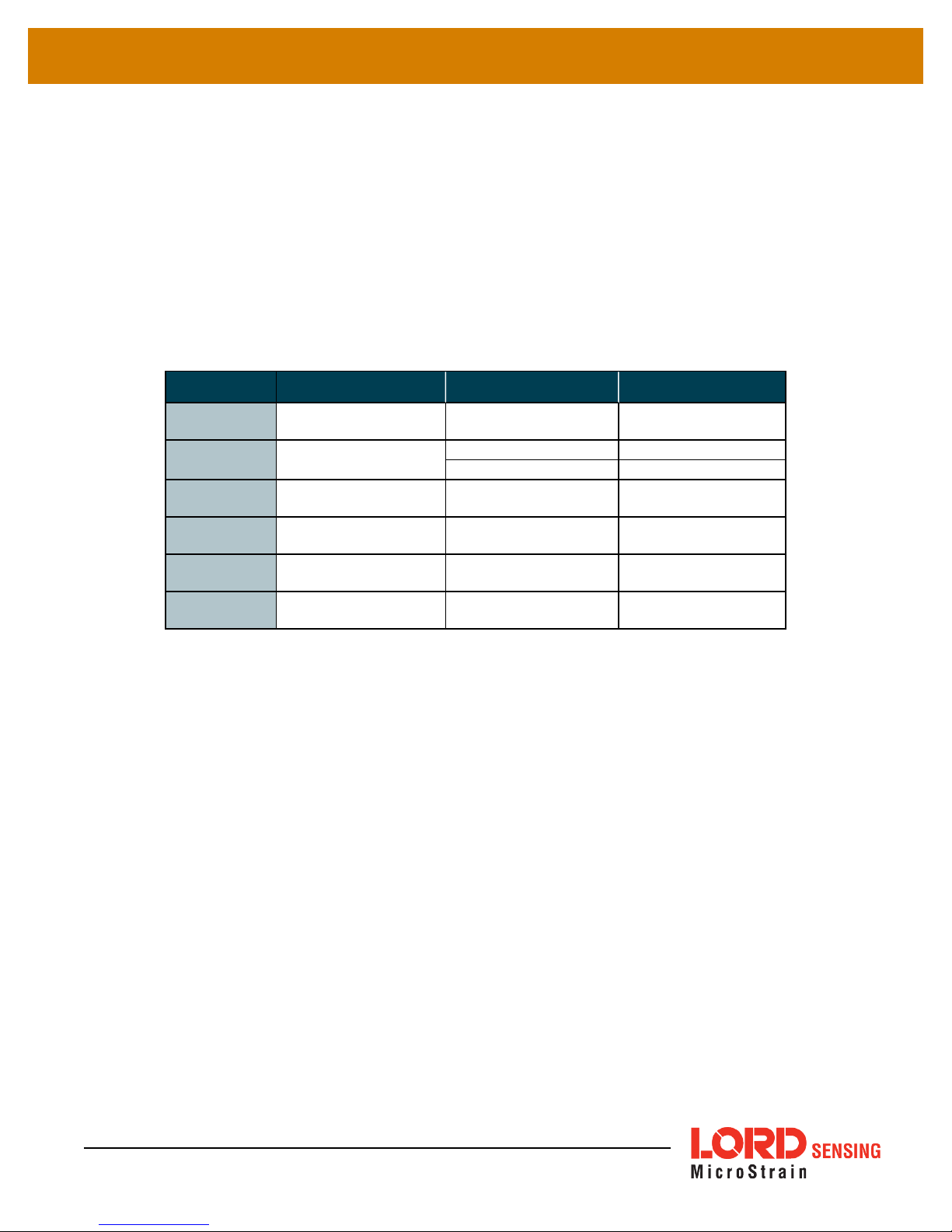
Field Description Format Range
PGN
Address
Payload
Ch Comp
Condition
Value
SAE CAN J1939
header
sensor node address
list of packet alias
values
channel for
conditional formula
condition for
conditional formula
threshold for
conditional formula
hexadecimal 0xFF00 to 0xFFFF
decimal 1 to 65534
hexadecimal 0x0001 to 0xFFFE
text separated by
spaces
text (example:ch1)
mathematical
operator
single precision
floating point
(example:ch1 ch2)
in range*, <, >, =, ≠
decimals within
format constraint
* For the "in range" option, the Value field is two values separated by a comma (ex. 4,5), ordered
fromleastto greatest. The values listed are included in the comparison.
Table 6 - Broadcast Message Configuration Fields
PGN: (Parameter Group Name) unique hexadecimal packet identifier
Address: is the numerical address of the sensor node the data to be sent is from. The node
address is assigned when the node is manufactured. The number is provided with the node
and displayed in SensorConnect when connected.
Payload: Payload are the data values to include in the packet. They are listed by name in the
sequence they will be sent. If the requested value cannot be found (for example, if the
nomenclature is wrong) the defined J1939 packet will not be sent.
on page 29
for the payload nomenclature. The byte counts are defined in the packet
definitions which can be found on Github.
Ch Comp, Condition and Value: Use these fields to create a condition for which packets will
be sent onto the CAN bus. Ch Comp (Channel Compare) is the data source for the condition
formula, and the Condition and Value define what mathematical operation to apply to it.
See Data Alias Definitions
25
Page 26

WSDA®-2000 User Manual
To enter the broadcast messages in the J1939 menu, type in the appropriate field. When the PGN
field is selected, the Payload field will appear. If all values for the message are to be included, leave
the Ch. Comp, Condition and Value fields blank . Select Apply at the end of the row to save the
message designations. Once all designations are entered, click the Submit button to save the
configuration (
a file using the Download button.
Figure 13 - CAN J1939 Menu
). To save the configuration for future use, download to
Figure 15 - Broadcast Message Menu Example
To use a text file, structure the data in the following format. Leave fields blank if all values are to be
included.
[
PGN
]
NodeAddress=
Protocol=
Variant=
value
Payload=
Condition=
EXAMPLE:
value
value
value
channel name:operator:value
Node 31463 was sampled in low duty cycle mode. Sensors are connected to channel 1, channel 2,
and channel 3. For channels 1 and 3 all data measurements will be sent to the CAN bus. For the
sensor on channel 2, only data values over 1.8 will be sent.
[0xFF00]
NodeAddress=31463
Protocol=4
Payload=ch1 ch3
[0xFF01]
NodeAddress=35
Protocol=4
Payload=ch2
Condition=ch2:>:1.8
26
Page 27

WSDA®-2000 User Manual
Once created, save the text file and then upload it to the gateway by clicking the Browse for File
button in the J1939 menu. Navigate to the file, click OK, and then click the Submit button to save the
configuration (
Figure 16 - Upload Configuration File
Figure 16 - Upload Configuration File
).
In the example below, ch1 and the value 1 are used to demonstrate the acceptable values for the
Condition syntax.
In range:
Condition = ch1:in:1,5
Equal to:
Condition= ch1:=:1
Greater than:
Condition = ch1:>:1
Less than:
Condition = ch1:<:1
Not equal to:
Condition = ch1:!=:1
Host Bus Integration
o
Destination Specific Messages:
With this message format, data packets received from the sensor nodes will be passed onto the
J1939 CAN bus as received. An integrity check is made before sending the packet over the bus,
but no other process is applied before wrapping the data in the J1939 protocol. The receiving
CANJ1939 must be capable of responding to Transport Protocal Connection Management
(TP.CM). Only one sensor data packet will be sent in each TP.CM exchange. To parse the data,
the destination will need to understand the LORD Sensing Wireless Sensor Networks Data
Communications Protocol, which is defined online at Github.
27
Page 28

WSDA®-2000 User Manual
o
Broadcast Messages:
With this message format, the receiving system will need to be programmed to understand the
user defined payloads for each PGN sent. Specifically, the user will need to inform the receiving
system which order the data values are stored in the payload and how many bytes each data
value is made up of.
The destination will need to understand the LORD Sensing Wireless Sensor Networks Data
Communications Protocol for Low Duty Cycle (LDC), Synchronized Sampling, and Histogram
packets (
sensor data packets will be broken up into multiple J1939 packets as required. In this scenario 7
bytes of sensor data packets are sent with a 1 byte J1939 sequence number to indicate its
position in the string of sensor data. This is done automatically and will appear seamless on the
receiving end.
see Data Alias Definitions on page 29
). Since J1939 only supports payloads of 8 bytes,
28
Page 29
WSDA®-2000 User Manual
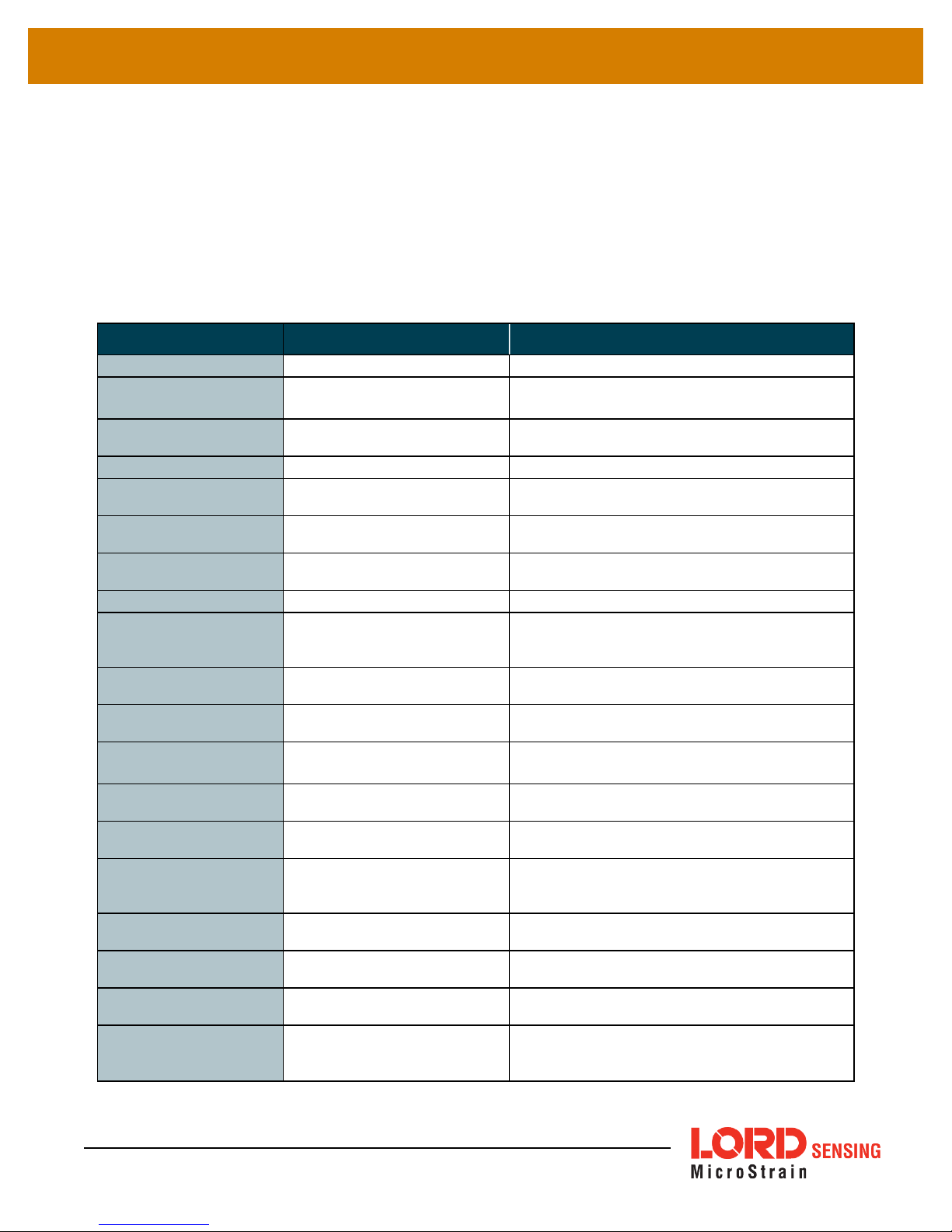
4.2.2 Data Alias Definitions
The names of data the sensor network produces and the WSDA can push onto the CAN bus are
defined below. All data is in big-endian format unless otherwise noted. Some data channels have
fixed sizes or depend on the node settings. Note: The Payload field of the Broadcast Message
Menu will also suggest values based on user-set configurations. To view the full list, select Payload
and hold while pressing the down arrow on the keyboard (
Packet definitions and details on the data included in each packet, go to: Github.
Value Definition Applicable Packet
hist
angle1 through
angle16
ch1 through ch16
dg1 through dg16
angleid
uptime
life
bin1 through bin21
binlowbound
binsize
proc_rate
angStr1 through
angStr16
utcseconds
utcnanoseconds
rms1 through rms16
ptp1 through ptp16
ips1 through ips16
cf1 through cf16
samplerate
See CAN J1939 Output on page 22
Histogram
The angle for which data is
being collected
Raw data channels (ex. ch4, is
the fourth channel of data)
Digital channels Asychronous Digital Only
Angle ID specified in the histogram packet
Uptime as specified in the
histogram packet
Fatigue life used as specified in
the histogram packet
Individual bins of histogram Structural Health (v1,v2)
Low end of stress histogram
starts at as specified in the histogram packet
Size of each bin as specified in
the histogram packet
Sample rate of data behind the
histogram
Strain for an angle
Seconds portion of timestamp
in data packet
Nanoseconds portion of
timestamp in data packet
RMS value of specified channel (ex. rms1 is rms value of
channel 1)
Peak-to-peak value of specified
channel
Velocity of specified channel in
inches per second
Crest factor for specified channel
Speed of data sampling
LDC, Synchronized Sampling (v1, v2)
Structural Health (v1)
Structural Health (v1)
Structural Health (v1,v2)
Structural Health (v1,v2)
Structural Health (v1,v2)
Structural Health (v2)
Raw Angle Strain Specific Angle Mode, Distributed Angle Mode
Synchronized Sampling (v1, v2)
Synchronized Sampling (v1, v2)
Derived LDC Packet (v1), Derived Synchronized
Sampling Packet (v1)
Derived LDC Packet (v1), Derived Synchronized
Sampling Packet (v1)
Derived LDC Packet (v1), Derived Synchronized
Sampling Packet (v1)
Derived LDC Packet (v1), Derived Synchronized
Sampling Packet (v1)
LDC (v1,v2), Syncrhonized Sampling (v1,v2), Strutural Health (v1,v2), Derived LDC (v1),Derived
Syncrhonized Sampling (v1)
). For
29
Page 30
WSDA®-2000 User Manual
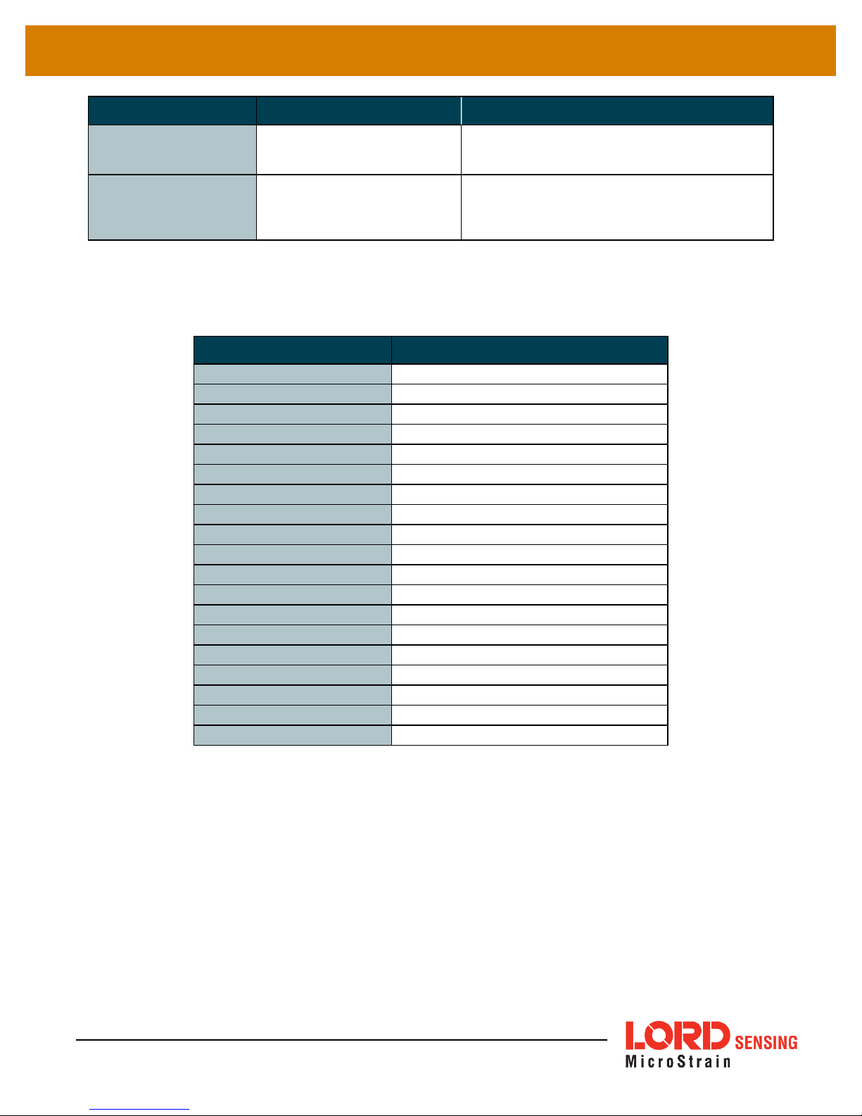
Value Definition Applicable Packet
tick
noderssi
The following table summarizes the Diagnostic Channel definitions.
current_state
idle_time
sleep_time
active_time
inactive_time
reset_counter
lowBatteryFlag
sweepIndex
badSweepCount
totalTx
totalReTx
droppedPackets
bit
eventindex
extPwr
intTmp
syncRtry
syncFail
secSinceSync
LDC (v1,v2), Syncrhonized Sampling (v1,v2),
Packet tick number
RSSI value of node
Derived LDC (v1),Derived Syncrhonized Sampling (v1)
Syncrhonized Sampling (v1,v2),Derived Syncrhonized Sampling (v1), Asynchronous (v1),
Asynchronous Digital and Analog (v1), Structural
Health (v2), Diagnostic (V1)
Table 7 - Data Channel Definitions
Value Definition
Current state of the node
Time the node spends in idle
Time node spends in sleep
Time node spends actively sampling
Time nodes spends inactive
Number of resets
Low battery warning
Current sweep index
Number of bad sweeps (discarded data)
Total transmissions
Total transmission retries
Number of dropped packets
Built in test results
Index for number of events
External power flag
Internal temperature
Number of synchronization retries
Number of synchronization failures
Time since last synchronization
Table 8 - Diagnostic Channel Definitions
30
Page 31
WSDA®-2000 User Manual
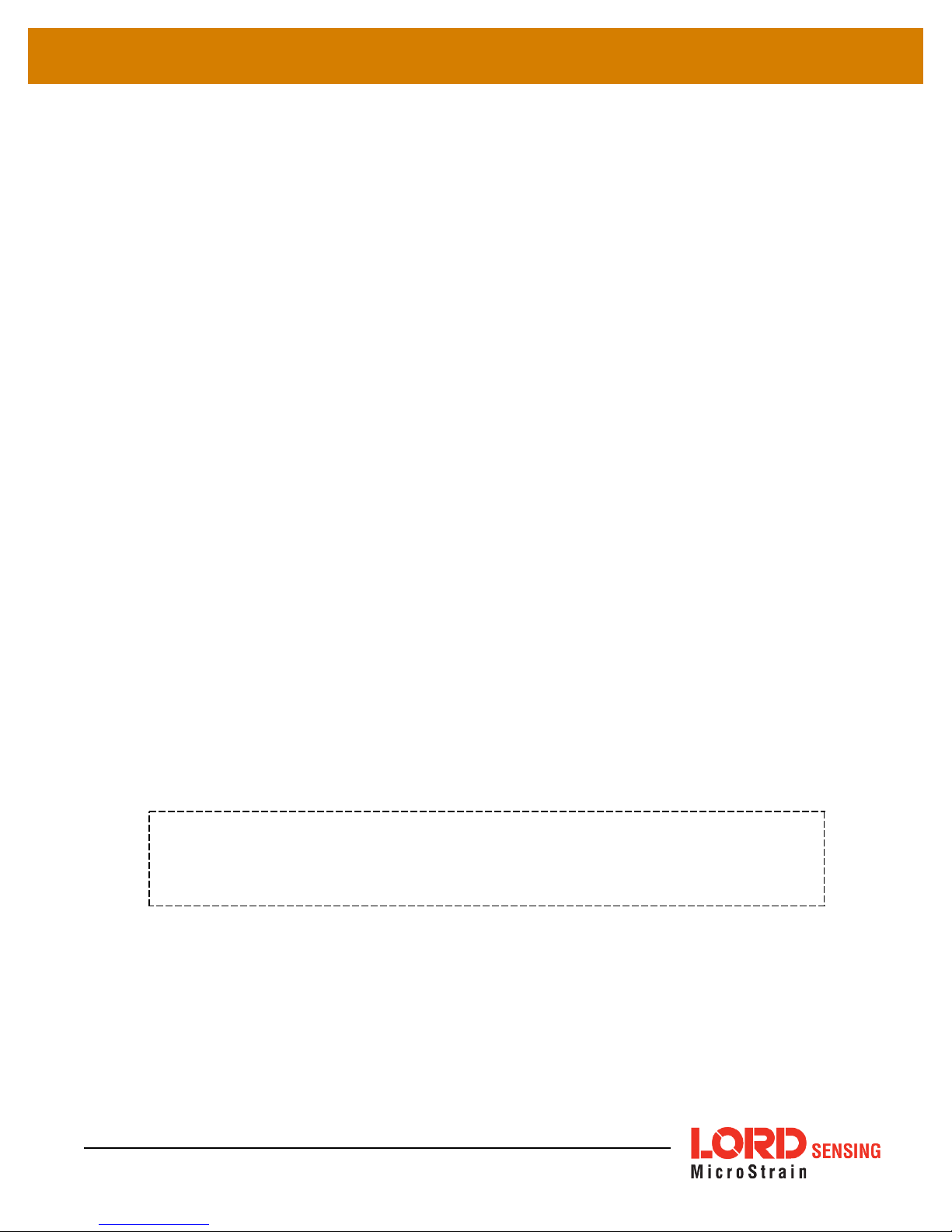
4.2.3 SensorCloud™ Upload Filter
By default, the WSDA - 2000 uploads all sensor data stored in the gateway memory to
SensorCloud™. The Upload Filter function allows the user to select the data to be uploaded.
Figure 17 - Data Upload Filter
The Upload Filter menu describes how to set up a filter. Nodes and node channels can be
collectively set to be included (Only Upload the Listed Channels) or excluded (Do Not Upload the
Listed Channels) by using the Change Filter Type button. For address and channel nomenclature
see Data Options Menu on page 21
. The Upload Filter can be set before or after data upload has
been initiated. If data has already been received from the node, refer to the Node List to verify which
node and channel data has been saved. Use the Clear All button to delete all node filters.
NOTE
The Change Filter Type function affects all nodes in the filter list. When applied, it sets
all nodes in the list and cannot be used for individual nodes.
31
Page 32

WSDA®-2000 User Manual
4.2.4 WSDA Data Downloader Calibration Coefficients
The Calibration feature allows the user to specify coefficients for converting between engineering
units with a linear relationship, and to correct for sensor biases in sensor data saved in the gateway
memory.
The coefficients are applied when data is downloaded from the gateway to a host computer using
the WSDA Data Downloader and are in addition to any conversion values assigned to the sensor
channel during node configuration (
node User Manual). This feature is particularly useful for porting collected data into third party
applications like Microsoft Excel, custom software, or data analytic software when different
coefficients are desired than what was used when the data was acquired.
see Channel Configuration on page 1
as well as the applicable
The data to apply the coefficients to is designated by entering the source node address and channel
numbers. For the nomenclature used for the address and channel
21
. The coefficient values are entered for the designated channels. The values for each are
described below and are also available in the calibration help menus accessible by clicking the +
symbol next to Field Definitions (
the Add button after entering the desired values in each field.
Address: sensor node address
Channel: sensor channel on the designated node
32
Figure 18 - Calibration Menu
Figure 18 - Calibration Menu
see Data Options Menu on page
). To use the Calibration feature, click
Page 33

WSDA®-2000 User Manual
The conversion formula assumes a linear relationship between the original units (such as A/D bits)
and new engineering units (such as ), and it is expressed mathematically as
engineering units at a given point (measurement),mis the slope of the line that represents the linear
ratio,xis the original unit value at a given point, andbis a unit conversion offset (in the case of unit
conversions) or the fixed zero load offset of the sensor (in the case of measurement calibration
coefficients). Negative values may be entered for any coefficient.
Slope: is the linear scaling slope coefficient. The slope is the ratio of original units to new
engineering units (EU), and it is used to convert the sensor measurements. The slope conversion
value will vary depending on the engineering units desired. For example if the original unit is A/D
values (bits), and the desired engineering units are acceleration in g-force, the slope conversion
would describe how many bits equal one unit ofg-force (bits/g). Mathematically, the slope ismin the
formula
Offset: is the linear scaling offset coefficient, and it is typically the starting output value of the sensor
with no load applied (in the original units). Mathematically, the offset isbin
y = mx +b
y=mx+b
, whereyis the
.
y = mx +b
.
Low Limit: optional data threshold value that will generate a data- out- range indicator if
measurement is below the value
High Limit: optional data threshold value that will generate a data- out- of- range indicator if
measurement is above the value
Unit: user defined long name of calibrated unit
Symbol: user defined short name of calibrated unit
EXAMPLE:
Sensor node 34163 is measuring temperature in degrees Celsius on channel 1. Calibrated data is
desired to be in Fahrenheit with indicators if the measurement goes below 0 F or above 100 F. The
conversion for Celsius to Fahrenheit is: F = C*1.8 +32 (y = mx +b)
Address
34163 ch1 1.8 32 0 100 Fahrenheit F
Channel Slope Offset
Low
Limit
High
Limit
Unit Symbol
33
Page 34
WSDA®-2000 User Manual
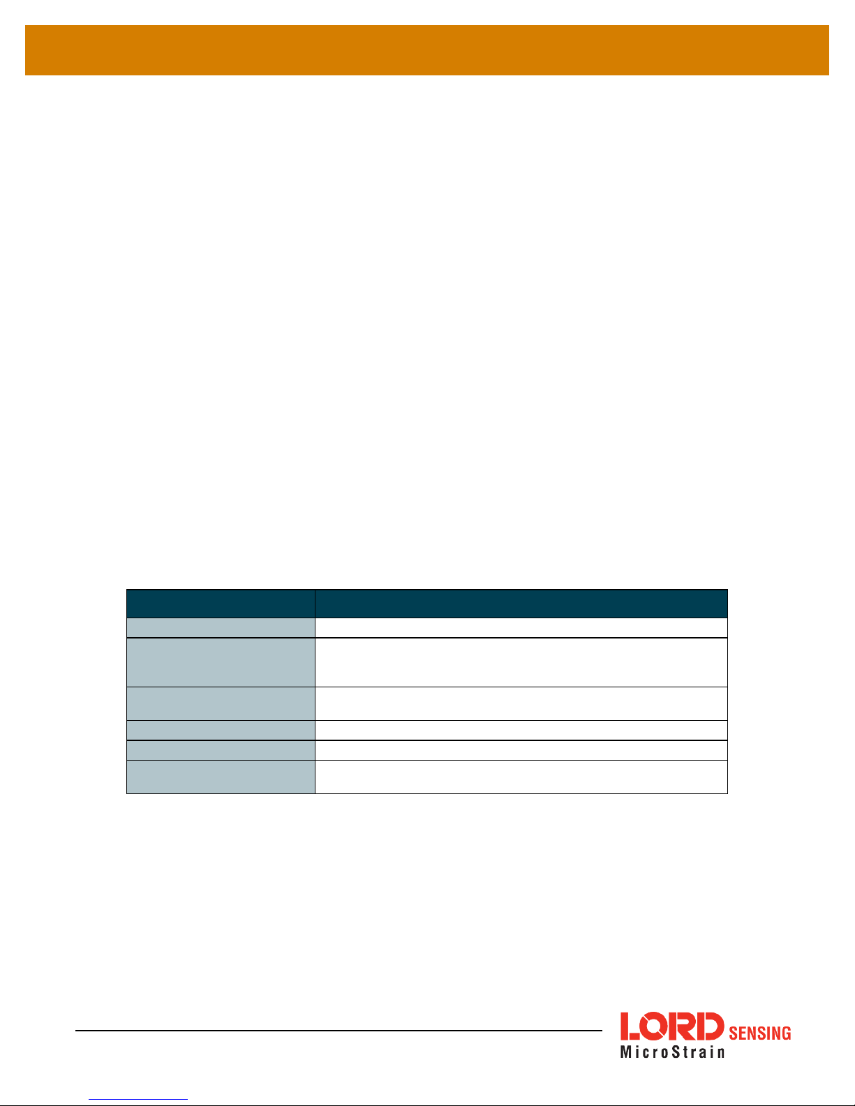
4.2.5 Clear Stored Data
The Clear Data feature is used to erase all sensor node data from the gateway's internal memory.
Before erasing, the user should confirm that all data has been transmitted to SensorCloud™. The
Current Data Size display indicates the amount of data currently stored in the memory. To clear
data, click the Clear All Data button and the data will be erased.
Figure 19 - Clear Data Menu
4.3 Gateway Tools Menu
The Tools menus provide the user a means to configure, troubleshoot, and update the WSDA-2000
settings.
Table 9 - Tools Menus
Menu Description
Diagnostics
Configuration
Time Options
Reboot
OS Upgrade
Change Password
provides a summary of the menus under the Tools category.
Reports results of periodic diagnostic checks
Gateway settings adjustments such as communications configuration, device naming, and enabling and disabling of gateway
features
Configuration options related to how the gateway retrieves and uses
time
Restart and reinitialize the gateway without cycling power
Update the operating system software on the gateway
Change the user name and the password required at log-in to the
gateway Control Panel
Table 9 - Tools Menus
34
Page 35

WSDA®-2000 User Manual
4.3.1 Diagnostics
The diagnostics feature is used to troubleshoot the WSDA-2000. The diagnostics window displays
a report from the gateway internal log file. The log records the diagnostic checks from three possible
sources of error: the timing engine, SensorCloud™ data upload, and the data logger. These
diagnostic checks are performed once at every power up and then periodically as the gateway is in
on. If errors are reported in the Diagnostics menu, contact LORD Sensing Technical Support (
Technical Support on page 78
see
).
35
Figure 20 - Diagnostics Menu
NOTE
If SensorCloud™ Data Upload, J1939, or Data Logging are disabled (in the
Tools > Configuration menu) they will not be checked during the diagnostics
routine.
Page 36

WSDA®-2000 User Manual
4.3.2 Configuration
The Configuration menu allows the user to set parameters associated with WSDA-2000 operation.
The settings include configuring the communication settings, enabling and disabling operating
sequences, changing the node synchronization beacon state, and changing the gateway wireless
node communication frequency. Each setting is described below in detail.
Device Name: The device name in an alias given to the WSDA - 2000, so it is more easily
recognized. By default, the device name is not assigned. To enter a name, type it into the field and
click the Save button.
Local Live Connect: The Local Live Connect setting allows users to disable Live Connect on the
local network. This is important if data security is a concern. Disabling Live Connect prevents other
36
Figure 21 - Configuration Menu
Page 37

WSDA®-2000 User Manual
users on the network from accessing the data stream . If Live Connect is disabled it will not be
available for connecting to SensorConnect unless done remotely through SensorCloud™ (
Remote Connectivity on page 44
Data Logging: Data logging saves acquired data to the gateway internal memory, and also makes it
available to the CAN J1939 Bus, SensorCloud™, and a host computer through Live Connect.
Disabling data logging will prevent data only from being stored in the gateway internal memory and
from being uploaded to SensorCloud™. The data will still be available to SensorConnect through
Live Connect and for the CAN J1939 bus. The default setting is that all data logging is enabled.
When data logging is enabled the gateway waits for time synchronization (
page 39
frequency, and then begins logging data.
WSN Beacon On Startup:The beacon is used to precisely coordinate node data acquisition and
data transmission in the wireless sensor network (WSN) during synchronized sampling.
Network Mode: The network mode determines whether the gateway has a dynamic or a static IP
address, which is used to identify it on the network. A dynamic, or DHCP network, automatically
assigns the gateway an IPaddress. The static IPsetting allows manual assignment of the IP
address. A static IPaddress is required if the network does not have a DHCP server or if the
gateway will be connected directly to a host computer and not used on a network. The default
setting is for a DHCP network.
), sets the node synchronization beacon, sets the gateway wireless node communication
see
). The default is for Live Connect to be enabled.
see Time Options on
If Static IP is selected, additional menu settings will appear (
Figure 22 - Static IPSettings
). The
Static IPAddress is the IPAddress to which the gateway will be assigned. This cannot be the
network address or the broadcast address of the subnet. The Static Subnet Mask defines the
range that the gateway can communicate (on the subnet). For example, if the gateway IP Address
is 192.168.0.100, and the subnet mask is 255.255.255.0 the gateway can communicate with all
addresses between 192.168.0.0 and 192.168.0.255. The Static Gateway option allows users to
define an address the gateway can communicate with outside of its subnet. This requires the
gateway to be able to access the internet on a static network.
Figure 22 - Static IPSettings
37
Page 38

WSDA®-2000 User Manual
To setup the host computer for direct communications with the gateway, the host computer IP
address must be changed so that it has the same subnet as the gateway. The gateway subnet in the
example above is the first three sets of numbers in the IPaddress (192.168.0). The last set of
numbers (100 in the example) will be the unique identifier for each device on the network (the
gateway, computer, and other devices will each have a different number).
To change the IP address on a computer with a Window operating system, try the following steps:
1. Find the active Local Area Connection. Go to the Control Panel, and click on the Network
Connections folder.
2. Right-click on the active Local Area Connection, and select properties.
3. Scroll down, and double-click on Internet Protocol (TCP/IP).
4. In the window select Use the Following IPAddress.
5. Enter the subnet into the field entitled IP Address, and add a fourth number. It can be any
number between 0 and 255, except the number that the gateway or any other device on the
network is using.
6. In the Subnet Mask field, enter 255.255.255.0.
7. Save and exit the menus. Setup is complete.
J1939: The J1939 CAN output allows sensor data to be pushed out to a user-designed J1939 CAN
bus through the WSDA-2000 multi-port connector. For more information
on page 22
. The default setting is for the J1939 output to be enabled.
see CAN J1939 Output
SensorCloud: The SensorCloud™ feature allows enabling and disabling of the transmission of
sensor data from the gateway internal memory to the web-based SensorCloud™ database. It also
allows remote access to the gateway Control Panel through Live Connect (
Connectivity on page 44
). When enabled the gateway will upload newly received data to
see Remote
SensorCloud™ at two minute intervals. In other words, it will transmit new data, wait two minutes,
and then transmit any additional new data. The overall transmission time varies with sampling
settings, quantity of data, and internet connection speeds.
38
Page 39

WSDA®-2000 User Manual
4.3.3 Time Options
The Time Options menu allows configuration options related to how the gateway retrieves and uses
time. TheWSDA-2000 has two on-board clocks: the System Clock and the Real Time Clock (RTC).
The purpose of the System Clock is to provide the operating system with a time source. The
purpose of the Real Time Clock is to provide time updates to the System Clock and to provide a
reference for the node synchronization beaconing function.
During normal operation, the WSDA-2000 synchronizes time from enabled time sources starting
with the most accurate. On boot-up, the WSDA-2000 will try to get a new time. If it is unable to, it will
check to see if it already has a non-expired time from the first source. If not it will move on to the next
source. During boot-up the WSDA-2000 must successfully synchronize time before it can begin
data acquisition. Once synchronization has occurred, the WSDA-2000 will continue to query the
time source every hour, however synchronization is not required to continue data acquisition.
Manually setting time on the WSDA-2000 will immediately override any synchronization attempts
and allow data acquisition to start.
The WSDA-2000 can synchronize its system time from four different time sources: Network Time
Protocol (NTP)time servers, manual user entry, the last known time reference, or from an attached
device with GPS.
l Time servers allows the WSDA-2000 to synchronize with external servers that provide the
NTP service. A list of time servers is provided and can be modified by the user. This option
requires connection to a NTPserver and is the most accurate time source (with the
exception of GPS).
39
Figure 23 - Time Options Menu
Page 40
WSDA®-2000 User Manual
l Manual time synchronization utilizes a time entered by the user. Enter the time in the
System Time field, and select the Set System Time button.
l Last Known synchronizes to the last time recorded on the WSDA-2000. This could be from
the internal Real Time Clock (RTC) or a file on the gateway.
l GPS allows the WSDA-2000 to synchronize with a compatible external GPS device for
extremely accurate time.
Using GPS as a time source is only available in the Time Options menu when a GPS
integrated device, such as a LORD Sensing GPS enabled inertial sensor, is connected
to the WSDA - 2000 customization serial port. For more information refer to see
Recommended Sensors on page 1 or contact LORD Sensing Technical Support (see
Technical Support on page 78).
To select the time source check the Enabled check-box next to the source name in the Time
Sources menu. Each time source also has an accuracy field and an expiration field. Accuracy is
fixed and dependent on the source. Expiration represents how long the time synchronization is valid
for, and it is set by the user.
NOTE
System Time displays the current time being used by the gateway. Time can be manually entered
by typing directly into the field and selecting the Set System Time button. This function is normally
used when no other time source (Time Servers, GPS, etc.) is available. If the time is set forward
more than an hour from the host computer, the Control Panel web session will be expired and the
user will have to log in again.
The Time Servers selections allows the user to set which time servers the gateway uses to
synchronize time, and in what order it attempts to do so. The time servers are displayed in a list with
the first server, order 0, being the first server checked. The time server must support NTP for the
gateway to use it. The WSDA-2000 comes pre-configured with some known time servers.
To insert a new time server, fill in the last line Order column with the numerical order to place the
time server in the list. Next enter the host name of the time server in the Hostname column. Click the
Insert button.
To delete a time server locate the time server in the list, and click the Delete button next to it.
To change the order of an existing time server locate the time server on the list, and enter the new
order number in the Order column. Click Apply. Other servers with the same numerical designation
will automatically be moved.
40
Page 41
WSDA®-2000 User Manual
4.3.4 Reboot
The Reboot option allows the user to restart and reinitialize the gateway without cycling power.
To reboot the WSDA-2000, select the Reboot button. A three stage boot-up sequence will start, as
described in
minutes. Once booted, log in into the Control Panel as normal.
Table 10 - Reboot Indicators
Initial Power On
Booting Up
Fully Booted
Stage
. The boot-up process will take between two and three
Indicator Behavior
CLOUD WSDA POWER
ON red ON red ON green
ON red flashing blue ON green
ON green and/or
flashing blue
ON green ON green
Table 10 - Reboot Indicators
41
Page 42

WSDA®-2000 User Manual
4.3.5 OperatingSystem (OS) Upgrade
Periodically, new versions of the WSDA-2000 operating system will be released to add features or
make other updates to the system. On the recommendation of LORD Sensing Technical Support,
gateways can be upgraded to the latest available operating system to take advantage of these new
features or to correct operating issues.Updates may be found on the LORD Sensing website (
Technical Support on page 78
see
).
Figure 24 - OS Upgrade Menu
1. Download the upgrade file from the LORD Sensing website or LORD Sensing Technical
Support.
2. As needed, extract the contents of the zip file into a folder on the computer. Verify there is a
file with a .wsda_os extension.
3. Select the OS Upgrade button in the gateway Control Panel.
4. Select the Browse button, and navigate to the folder containing the update file provided
(example: firmware_v2.3.3.wsda_os).
5. Select the Open button, and then Upload. There are two parts to the upgrade: the upload and
the actual upgrade. Once the upload reaches 100%, the status bar will reset and begin the
upgrade process status. The entire upgrade can take fifteen to twenty minutes.
42
Page 43

WSDA®-2000 User Manual
4.3.6 Change Password
The Change Password feature is used to change the username and the password required at log-in
to the WSDA-2000 Control Panel.
The default username and password are:
a. Login: wsda
b. Password: wsda
Enter the current username and password and then the new password twice and select Submit.
Figure 25 - Change Password Menu
43
Page 44

WSDA®-2000 User Manual
5. Remote Connectivity
Some SensorCloud™ data plans allow remote access to the WSDA-2000 through the SensorCloud™ web
interface. This allows access to the gateway Control Panel (including data downloading) and to Live
Connect and SensorConnect for remote configuration of gateways and nodes. Data downloading from
the gateway memory is also available in this way. Access is obtained through a secure web interface,
although local installations of Live Connect and SensorConnect are required on the host computer to
access the nodes.
To begin, log in to SensorCloud™ (
Access the Control Panel Remotely
1. While in SensorCloud™ open the Devices menu, and select the device Configuration link
(
Figure 26 - Gateway Configuration
2. Select the Control Panel button (
SensorCloud™ account does not include the feature and must be upgraded.
see Data Access on page 1
).
Figure 26 - Gateway Configuration
).
5. Remote Connectivity
). If it is not present, the
3. Log in to the Control Panel when prompted. All Control Panel features are now available
(
see Gateway Menu Navigation on page 18
44
).
Page 45

WSDA®-2000 User Manual
Download Data Remotely
1. Download the WSDA Data Downloader from the WSDA-2000 product page at:
http://www.microstrain.com/wireless/WSDA-1500 >Downloads > Software.
2. Connect to the gateway Control Panel as described above.
3. Copy the URL from the browser address bar when in Control Panel (
Panel URL
).
Figure 27 - Control
4. Open the WSDA Data Downloader program and paste the address into the WSDA URL
field.
5. Enter the log-in credentials for Control Panel, and select Connect to WSDA.
6. Enter SensorCloud™ credentials when prompted, and use WSDA Data Downloader as normal (
see on page 1
).
Figure 27 - Control Panel URL
Access Live Connect Remotely
1. In the device configuration menu, select the Live Connect button (
Connectivity
). If the button is not present, the SensorCloud™ account does not include the
5. Remote
feature and must be upgraded.
2. When the button is selected a file download (info.live_connect) will begin. Open the file
when the download is complete, and Live Connect will open automatically. The device will
appear in the Live Connect window under User Defined WSDA's (
Connect Connection
).
3. Use Live Connect to connect to the gateway control panel (
14
) or to SensorConnect (
see Connecting to Nodes and on page 1
see Gateway Settings on page
Figure 28 - Remote Live
) as normal.
45
Page 46

WSDA®-2000 User Manual
Figure 28 - Remote Live Connect Connection
46
Page 47

WSDA®-2000 User Manual
6. Using the Beacon
In synchronized sampling, the beacon feature is used to coordinate sampling and transmission timing
between multiple nodes. The primary purpose is to avoid data collision, guarantee timing between
samples from different nodes, and to time-stamp the data. The beacon cannot be used in any another
sampling mode.
To acquire tightly synchronized, absolute wireless network times, enable the beacon from the WSN
Beacon On Startup setting in the gateway control panel (
beacon is enabled, the gateway broadcasts a data message once every second containing a
Coordinated Universal Time (UTC) time stamp, and it is used to update each node’s real time clock
(RTC). This continuous synchronization beacon, coupled with the accuracy of the gateway and node
clocks (+/- 3 ppm drift), provides a node- to- node synchronization within ±50 microseconds. The
gateway receives the UTC from the host computer, so the host must be connected to a UTC time
server to achieve that accuracy. There is some lag inherent in the Microsoft Windows distribution of the
UTC. This dictates the overall accuracy of the time-stamp, but the synchronization times between the
gateway and nodes will be consistent because of the accuracy of the embedded RTC clocks.
see Configuration on page 36
.) When the
Nodes must be on the same transmission frequency (channel) as the gateway to receive the beacon
broadcast command. When the beacon is active, the gateway device status indicator will pulse blue
once per second. When the nodes connected to the gateway are in synchronized sampling mode, the
network can be put to sleep by turning off the beacon and then resuming transmitting once the beacon
is enabled. Any node that is actively sampling in synchronized sampling mode on the same frequency
as the gateway will synchronize to it automatically if the beacon is activated.
To avoid interference with other devices it is recommended that the beacon be disabled when not in
use. Do not operate multiple gateways on the same frequency.
To enable and disable the beacon in SensorConnect™, select On or Off from the Toggle Beacon tile. A
green pop up window will appear confirming the successful action. Note: When starting a synchronized
network using SensorConnect™ , it automatically starts the beacon using the host computer's time, not
the gateway's time, which may negatively impact the quality of the synchronized data.
Figure 29 - Synchronized Sampling Beacon
47
Page 48

WSDA®-2000 User Manual
6.1 System Bandwidth in Synchronized Sampling
When using synchronized sampling all nodes in the wireless network are queried and given time
slots of various lengths based on their configuration (# of channels, sample rate, etc.). Nodes will
only transmit data during these time slots, therefore eliminating over-the-air data collisions. The total
time available for node transmissions is defined by the system bandwidth. Because the system
bandwidth is finite, only a fixed number of nodes can be supported when using synchronized
sampling. The number of nodes is largely dependent on node configuration, as each consumes part
of the bandwidth. Use the online network bandwidth calculator to determine the bandwidth capacity
for a particular system configuration: http://www.microstrain.com/configure-your-system
6.2 Synchronized Sampling with Multiple Gateways
If there are multiple gateways in the system, a Global Positioning System (GPS) time source can be
used to synchronize time between the gateways. Only gateways with attached GPS devices, such
as a LORD Sensing GPS or GNSS- enabled inertial sensor, will have this option (
Recommended Sensors on page 1
the GPS time source is on the order of micro-seconds.
see
). The gateway-to-gateway synchronization for systems using
Another option available on the WSDA- 1500 gateway is to use an NTP time reference from the
internet. As there is lag inherent to using the internet to get a NTP time, it is not recommended for
synchronizing multiple gateways. This option would have a gateway-to-gateway synchronization on
the order of 10’s of milliseconds. A good compromise would be to use of a local NTP time reference.
This would reduce the gateway-to-gateway lag to milliseconds. For information on how to adjust the
times settings
see Time Options on page 39
.
48
Page 49

WSDA®-2000 User Manual
7. Sensor Node Access
7.1 Connect to Nodes
Several methods can be used in SensorConnect to establish communication with the nodes: the
automatic node discovery on the same frequency, automatic node discovery on a different frequency,
and add node manually.
7.1.1 Automatic Node Discovery on Same Frequency
If the base and node are on the same operating frequency, the node will populate below the
Base Station listing when powering on the WSDA-2000.
Figure 30 - Node Discovered On Same F requency
7.1.2 Automatic Node Discovery on Different Frequency
If a red circle with a number appears next to the Base Station, the node is operating on a
separate radio channel. Select the Base Station and then select the Nodes on Other
Frequencies tile.
Figure 31 - Node On Other F requency
49
Page 50

WSDA®-2000 User Manual
Highlight the new node being added and select Move Node to Frequency (#).
Figure 32 - Move Node
50
Page 51

WSDA®-2000 User Manual
7.1.3 Manually Add Node
Adding a node manually requires entering the node address and its current frequency setting.
Figure 33 - Add Node By Address
If the node was successfully added, two confirmation messages will appear and it will be
listed under the Base Station.
51
Figure 34 - Add Node Confirmation
Page 52

WSDA®-2000 User Manual
If the node failed to be added, a failure message will appear. This means the node did not
respond to the base station which could indicate the node is not in idle mode or it may be on
another frequency. If "Add Node Anyway" is selected, it will associate that node with the
channel entered but it is likely there will be a communication error. If the node was not in idle,
move the base station to the frequency of the node and issue a "Set to Idle" command.
Figure 35 - Failure to Add Node
52
Page 53

WSDA®-2000 User Manual
7.2 Configure Node
Node settings are stored to non-volatile memory and may be configured using SensorConnect. To
access the node configuration menu,under Devices select the node and then the Configure tile.
The configuration menus show the channels and configuration options available for the type of node
being used.
Figure 36 - Node Configuration
7.3 Configure and Start Sampling
To start a sampling session, nodes can be selected individually by selecting the Node name and then
the Sample tile.
53
Page 54

WSDA®-2000 User Manual
To sample multiple nodes as a group, select the Base Station and then the Sampling Network tile.
As a group, they will all be set to the same sampling mode. When the Base Station is selected, all the
nodes will appear in a list with a check mark to the left, all of the nodes checked off will be included in
the sampling. Uncheck the nodes to be excluded from the sampling.
Figure 37 - Network and Node Configuration Menu
l Synchronized - By selecting Synchronized, all nodes in the network will periodically synchronize
their time clocks to a beacon that is broadcasted by the WSDA gateway. Each beacon contains
a UTC timestamp, allowing nodes to timestamp their collected data within an accuracy of +/- 50
us.
Each node will also buffer data and transmit this data in time-slots allocated prior to sampling.
Using time-slots assures the transmissions will not “collide”, or corrupt each other. It also
provides a means for efficiently scaling the size of the network to allow as much data throughput
as possible.
54
Page 55

WSDA®-2000 User Manual
If Synchronized is deselected, the node will not require a beacon time source and will transmit a
data transmission for each measurement sweep. The user should deselect Synchronized if,
either low latency, or the lowest possible power at slow sample rates, is required.
l Lossless - The user can achieve near lossless data collection in most environments through the
use of data buffering, radio acknowledgments, and retransmissions. Each node buffers collected
data and timestamps to an internal 2 Mbit FIFO buffer. For each transmission, data is pulled from
this buffer. Upon receiving the data packet, an acknowledgment is sent from the WSDA
gateway providing the beacon. The node will retransmit data until this acknowledgment is
received. Inherent overhead in the transmission scheduling protocol assures the node time to
recover from periods of poor radio communication.
This feature allows lossless performance in environments where the node achieves as low as
50% packet error rate. It also allows for operation in situations where the gateway and node
move in and out of range of each other.
NOTE: The Lossless feature is only available when Synchronized is enabled. Disable Lossless if
the application requires consistent latency or can tolerate lost data.
l Node: Indicates the node address beside a box with a check mark. This box is checked by
default to include the node in the sampling. Uncheck the box to exclude the node from the
sampling.
l Channels: Provides a drop-down menu to select the desired sensor channels for the node.
l Sampling: Displays a drop-down menu to select the sample rate. "Continuously" samples
indefinitely, "For" specifies a fixed sampling time-frame, and "Bursting" allows short sampling
durations performed at periodic intervals.
l Data Type: Select the resolution of the data reported by the node. Selecting lower resolution
data will require fewer transmissions and lower power. Selecting "Float" will request the node
send data in the configured calibration unit type.
l Log/Transmit: Select "Log Only" to have the node store all collected data to flash memory for
later download. Select "Transmit Only" to have the node transmit all data while it is collected. Or
select "Log and Transmit" to have the node perform both operations.
l % Total: Indicates the percentage of total over-the-air bandwidth reserved for each node.
l Status: Displays network errors.
l Apply and Start Network: Applies all of the settings, starts the entire network, and starts the
Base Station's beacon.
l Apply and Arm Nodes: This setting allows the user to Arm all of the
nodes without starting the beacon. If the gateway has already enabled
55
Page 56

WSDA®-2000 User Manual
the beacon, this setting will keep the gateway's beacon.
l Apply Only: Saves the settings to memory and not start the network.
56
Page 57

WSDA®-2000 User Manual
4. Stop Sampling
To stop all (or selected) nodes on a network, select the Set Nodes to Idle tile and indicate with a check
mark which nodes are to be set to idle mode. If the Broadcast option is enabled, a signal to all nodes
(including unsolicited nodes) will be sent out to request they return to idle. The nodes must be moved to
the same frequency as well.
Figure 38 - Set to Idle
57
Page 58

WSDA®-2000 User Manual
8. Viewing Data
8.1 SensorCloud
Data acquired through SensorConnect is automatically saved on the host computer. Saved data can
be uploaded to SensorCloud. Ethernet gateways provide the option to automatically port the data to
SensorCloud during data acquisition for near real-time display and aggregation. Ethernet gateways
can also be configured to save data locally to internal memory for future upload to the host computer or
SensorCloud. Basic SensorCloud services are available to all users free of charge at:
http://www.sensorcloud.com/.
SensorCloud is based on cloud computing technology and is designed for long term collecting and
preservation of data. Features include time series and visualization graphing, automated alerts, and
data interpretation tools such as data filtering, statistical analysis, and advanced algorithm
development with the integrated MathEngine®interface. Leveraging the open source API,
SensorCloud can also be used to collect data from other LORD Sensing sensor products or third-party
systems. Basic SensorCloud services are available to all users free of charge at:
http://www.sensorcloud.com/.
58
Figure 39 - SensorCloud Log-in or Register
8.1.1 Navigating Menus
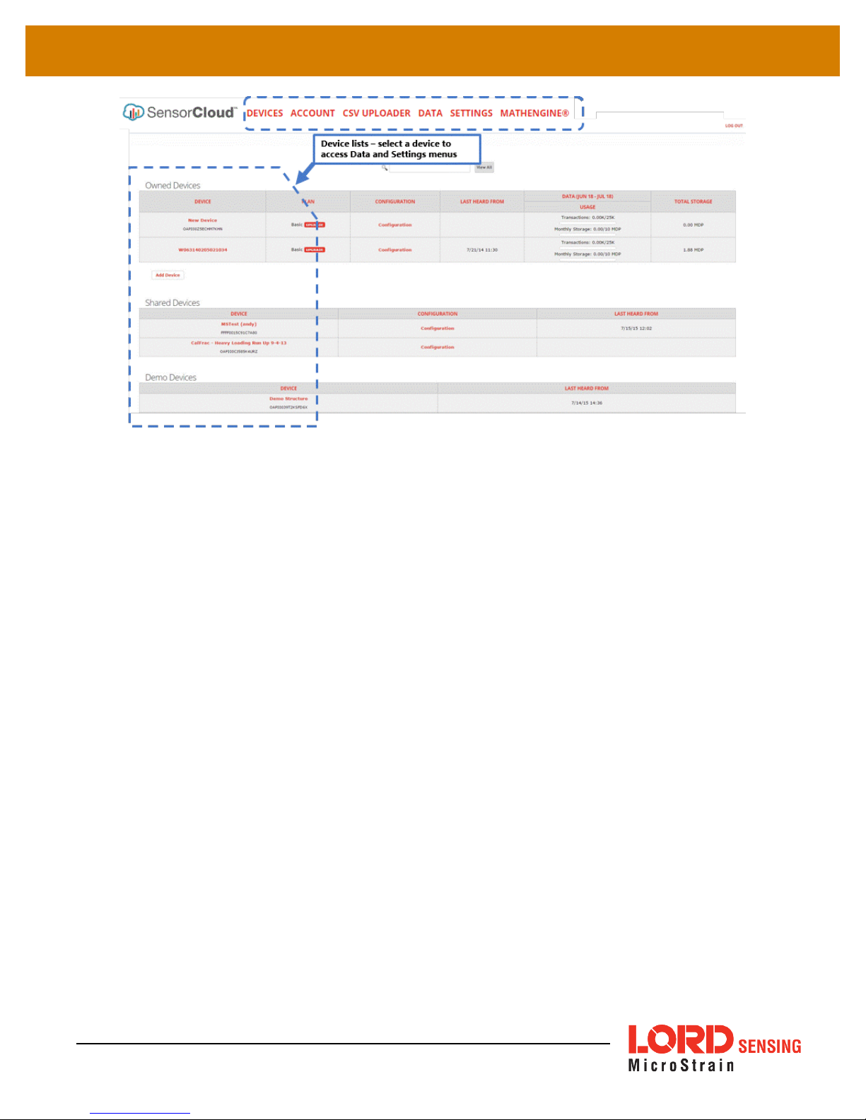
The SensorCloud interface has six main views . When logging in as a registered user, the Device
view is the default. Navigate to other views by clicking the view name at the top of the page (
40 - SensorCloud Menu Views
selected from the device list.
). The Data and Settings views are only available once a device is
Figure
Page 59
WSDA®-2000 User Manual
Figure 40 - SensorCloud Menu Views
Device - The device list shows every Ethernet gateway and API device associated with the
SensorCloud account, including owned, shared, and demo devices. This view provides links to each
device’s SensorCloud subscription plan, configuration options, and a summary of last communications
and data transactions.
Account - The account view is for logistic management of the SensorCloud account, such as changing
the log-in password, accessing user email, and reviewing billing information.
CSVUploader - The data upload feature enables data from any source (such as non-Ethernet LORD
Sensing gateways, or third-party sensor) to be uploaded to the SensorCloud platform. The data must
be in the LORD Sensing CSV format.
Data - This view is only available after a device is selected. It displays data that is collected from sensor
nodes or uploaded from files. Data selections are listed by node channel or a user-defined label and
can be enabled for display in the graph window. The interactive graph has navigational features such
as panning, zooming, and an overview graph for single-click access to data points or ranges. There are
also use and management features such as viewing the meta-data and downloading, embedding, and
tagging data graphs.
59
Page 60

WSDA®-2000 User Manual
Figure 41 - SensorCloud Data View
60
Figure 42 - MathEngine®View
Page 61

WSDA®-2000 User Manual
8.2 SensorConnect
8.2.1 Using Dashboards and Widgets
Collected data is viewed on the Data page through the creation of dashboards and widgets. Think
of dashboards as individual pages and widgets as an illustration on the page. Create multiple data
widgets on each dashboard to display sampled data as a time-series graph, text chart, or a simple
gauge that only displays the most current reading. This format provides an easy way to organize
many sensors and networks, and it allows the information to be displayed in the most appropriate
layout.
Figure 43 - FFT Graph in SensorCloud
61
Figure 44 - Viewing Data
Page 62

WSDA®-2000 User Manual
8.2.2 Navigating Graphs
Use the mouse along with the shift and control keys inside the graph window to adjust the data view.
8.2.3 Widgets Options
The widget configuration menu is different for each type of widget but typically includes sensor or
channel selections and widget settings such as titles and legends.
Control Action
Mouse wheel
Shift + mouse wheel
Mouse double-click
Shift + mouse left-click, drag left/right
Shift + mouse left-click, drag up/down
Ctrl +mouse left-click, drag
Table 11 - Graph View Controls
Zoom in/out onx-axis
Zoom in/out ony-axis
Zoom to extends
Zoom window left/right
Zoom window up/down
Zoom box
After adding a widget, left click to select and configure it in the Channels and Settings left sidebar
menu. Under Channels, the channel(s) for the widget can be enabled and disabled.
62
Figure 45 - Widget Settings Menu
Page 63

WSDA®-2000 User Manual
8.2.4 Time Series Widget Menu
The Time Series Widget menu has two features to help optimize sensor data collection for export to
a .csv file.
larger data sample (
Snap to Latest
captures the most recent data and
see Exporting Data Files on page 63
Figure 46 - Time Series Widget Menu
Zoom
isolates specific events from a
).
8.2.5 Exporting Data Files
To export data to a .csv file, select the Export Data button on the Time Series widget > Export >
name the document > save to the preferred location on the host computer.
Figure 47 - Exporting Data
63
Page 64

WSDA®-2000 User Manual
8.3 Using the Data Downloader
To view data using the Data Downloader, go to:http://www.microstrain.com/wireless/gateways,
select the product > Downloads > WSDA Data Downloader, run the application, and open the
window.
To find the WSDA URL, select the WSDAControl Panel tile from the Devices window in
SensorConnect™.
Figure 48 - Data Downloader Log-in Window
Figure 49 - Access WSDA Control Panel
64
Page 65

WSDA®-2000 User Manual
Figure 50 - WSDA URL
Copy and past the WSDA URL into the Data Downloader, enter WSDA Login and Password (
Gateway Settings on page 14
), and select "Connect to WSDA".
Figure 51 - Data Downloader Log in Window
See
65
Page 66

WSDA®-2000 User Manual
Figure 52 - Data Downloader Menu
The user may select to include all channels, or mark individual channels to include in the data
download, apply the calibration coefficients (
on page 32
), and/or to combine all of the sensors into a single .csv file. "Clear WSDA Data"
See WSDA Data Downloader Calibration Coefficients
permanently deletes all data on the gateway.
Select "Download to CSV" and choose where to save the file on the host computer.
Figure 53 - Save CSV File to Host Computer
66
Page 67

WSDA®-2000 User Manual
A green bar in the data downloader status window shows the progress and completion of the
download process. The saved CSV file is named WSDA_serial number_node address_timestamp
by default.
Figure 54 - Data Download Complete
Upload the CSV file to SensorCloud™ to view the data. For SensorCloud™ log in instructions, see
SensorCloud
under
Viewing Data on page 58
.
67
Page 68

WSDA®-2000 User Manual
9. Gateway Installation
9.1 Installation Recommendations
The WSDA-2000 is rated for indoor use only, unless housed in a ruggedized outdoor enclosure.
The gateway has two mounting tabs with holes for fastening(
be mounted in any orientation, but it is recommended that it is mounted in a way that optimizes the
wireless communications, typically with the antenna pointing upward. For more information
on page 69
.
Figure 55 - Gateway Installation
see NOTE
). It can
68
Figure 55 - Gateway Installation
Page 69
WSDA®-2000 User Manual
In the event of communication difficulties, it may be necessary to disable WIFI on the host
computer, or use a USB extender when collecting data.
The best method for ensuring optimal radio communication is to conduct an RF survey of the
installation site. This is easily accomplished in SensorConnect by using the range test feature to
quantify the radio signal strength (RSSI) in various scenarios.
instructions on using SensorConnect for measuring RSSI. The following are general guidelines for
maximizing communication range:
l Line of Sight (LOS) between the node and gateway.Try to avoid obstructions such as
buildings, terrain, vegetation, or other physical barriers.
l Increase the Mounting Height of the node to allow a clearer LOS path to the
gateway.Height above the ground is also important because reflections off of the ground
can interfere at the receiver. Generally, the higher above the ground the better.
l Minimize Radio Frequency Interference (RFI) from other wireless devices, especially
those operating in the same frequency range. This includes other nodes and 2.4 GHz
WIFI routers. If other wireless devices are required nearby, mount them at different
heights to minimize interference. Additionally, a different radio frequency may be selected
using SensorConnect software.
NOTE
See Range Test on page 70
for
l Minimize Electromagnetic Interference (EMI) such as that which is generated by power
transmission equipment, microwaves, power supplies, and other electromagnetic
sources.
l Metal Objects in close proximity to either antenna, particularly ferrous metals such as
steel and iron, can be problematic for wireless communications. The larger the object, the
greater the influence.
69
Page 70

WSDA®-2000 User Manual
9.1.1 Range Test
After establishing communication between node and gateway, use the range test feature in
SensorConnect to monitor the signal strength and to optimally position the nodes, gateway, and
antennae for installation. Maximum achievable range is determined by the gateway and node
power settings (found in the device Configure menu) and is highly dependent on the physical
environment surrounding the devices.
1. Select the node name > Range Test
Figure 56 - Range Test Menu
2. RSSI isa measure of signal strength between the node and the base station. A higher
RSSI value (closer to zero), will result in better node to base station communication.
Reliable communication can be achieved with a signal strength greater than -75 dBm, in
the absence of radiofrequency interference. Position the node and gateway antennas
where the best RSSI value is observed.
Figure 57 - Range Test Statistics
70
Page 71
WSDA®-2000 User Manual
9.2 Multi-port Connector Interface
The WSDA-2000 multi-port connector is currently only used for CAN J1939 output connections and
customized RS232 options, such as for use with LORD Sensing inertial sensors. The remaining are
used during manufacturing, or are reserved for future use. For mating connector information and premade cable assemblies
see Ethernet Gateway Accessories on page 1
.
Pin
Number
1
2
3
4
5
6
7
8
9
10
11
12
13
Signal
(future use)
(reserved)
+5V
(reserved)
GND
(future use)
(future use)
(not used)
(future use)
GND
(future use)
(future use)
+5V
Pin
Number
14
15
16
17
18
19
20
21
22
23
24
25
26
Table 12 - Multi-port Pin Designations
Signal
(future use)
+5V
(future use)
Tx
+5V
Rx
GND
1 PPS Out
1 PPS In
CAN High
CAN Low
(future use)
(future use)
71
Page 72

WSDA®-2000 User Manual
10. Troubleshooting
10.1 Troubleshooting Guide
72
Page 73
WSDA®-2000 User Manual
1. POWER
gateway or node does
not turn on
2. COMMUNICATION
no communication to the
gateway or node
Possible cause and recommended solution
1.1 node or gateway power is off
The status indicator LED on the device may be off. Turn the
device on, and the status indicator LED should illuminate.
1.2 external power is off or miswired
Verify the device power source is connected correctly and
powered on.
1.3 wrong power supply or voltage
Using a power supply other than the one specified for the
device (or an external supply that is outside of the device
operating range) could result in permanent damage to the
device or cause it to not work properly.
1.4 node battery is dead
If the node will not power on, the node battery may need to be
replaced.
1.5 node or gateway is damaged
If all power settings and connections have been verified, and
the node is still unresponsive, contact LORD Sensing Technical
Support (
2.1 node or gateway has no power
Verify the node and gateway have power applied and that
applicable power switches are on. Power is indicated on both
devices by a status indicator LED.
2.2 gateway has no communication with the computer
Verify gateway communication in the software. Check, remove,
and reconnect communications and power cables as
applicable.
2.3 node cannot be configured
Observe the node status indicator LED to determine the
device's state: boot, idle, sample, or sleep. If the node is
sampling or sleeping, it cannot be configured. In
SensorConnect, execute the Set to Idle command to put the
node in idle state, allowing configuration to occur.
If the user inactivity timeout is set very low, the configuration
menu will have to be entered quickly, before the timeout occurs,
putting the node back in a sample or sleep state.
2.4 node is out of range
Perform a bench test with the node in close proximity to the
gateway to verify they are operational. For range test and
installation recommendations . The system has been tested to
operate with the node and gateway up to 2 km apart with clear
line of sight.
2.5 node is not in normal boot mode
See Technical Support on page 78
).
73
Page 74

WSDA®-2000 User Manual
3. DATAACQUISITION
sensor data is missing
or incorrect
Possible cause and recommended solution
If the node status indicator shows the node booting in a mode
other than the normal boot mode, it can be bypassed by cycling
the node power rapidly three times, then leaving it on for normal
power up. In normal boot mode the communication can be
established with automatic node discovery (or manually) once
the boot process is complete and the node is in idle state. Startup mode can then be changed in the software.
2.6 node is sampling
Observe the node status indicator LED to determine the
device's state: boot, idle, active, or sleep. If the node is
sampling, it cannot be configured. In SensorConnect, execute
the Set to Idle command to put the node in idle state, allowing
configuration to occur.
2.7 node is sleeping
Observe the node status indicator LED to determine what state
it is: boot, idle, active, or sleep. If the node is sleeping, it cannot
be configured. In SensorConnect, execute the Set to Idle
command to put the node in idle state, allowing configuration to
occur.
2.8 gateway or node is damaged
Verify all connections, power, and settings. If available, try
installing alternate nodes and gateways one at a time to see if
the faulty device can be identified. If no conclusion can be
determined or to send a device in for repair, contact LORD
Sensing Technical Support (
78
).
3.1 no communication to node or gateway
Verify connections and power to the node and gateway. Verify
they are powered on and communicating with the software.
Enter a configuration menu to verify that the node can be
accessed.
3.2 sampling settings are incorrect
If the sampling mode, rate, or duration are not performing as
expected, enter the node configuration menu, and verify the
sampling settings.
3.3 sampling has not started
If sampling is occurring, the sampling mode will be displayed
next to the node name in SensorConnect. The node device
status indicator will also be flashing the sampling mode code. If
the node is not sampling, activate it in the software or with a
sample on start up boot sequence.
3.4 sensor is not connected correctly
Verify sensors connections and wiring. For non- standard
connections contact LORD Sensing Technical Support (
Technical Support on page 78
See Technical Support on page
See
).
74
Page 75
WSDA®-2000 User Manual
Possible cause and recommended solution
3.5 sensor channel not configured correctly
Verify that the sensor is configured on the correct channel and
has been enabled for data acquisition.
3.6 sensor calibration is invalid
External sensors come with a factory calibration value that is
entered during configuration. Internal sensors are factory
calibrated and should not need adjustment. The calibration data
is provided with the sensor when purchased.
75
Page 76

WSDA®-2000 User Manual
10.2 Communications Ports inWindows
®
Serial gateways (including USB gateways) have either a standard serial or virtual communications port
in Windows®. Windows®Device Manage can be used to determine what communication port the
gateway is connected to.
1. Click on the Windows®Start icon, and select Control Panel.
2. Navigate to the System menu, and select Device Manger. The menus may appear different
depending on the version of Windows and the View settings.
76
Figure 58 - Windows
®
System Menu
Page 77

WSDA®-2000 User Manual
3. In Device Manager, expand the view for Ports (COM and LPT). Active COM ports will appear
on this list with the COM port number. If no port is listed, the port is not recognized by the
computer, and no gateway communication can be established.
Figure 59 - Windows®Device Manger Menu
77
Page 78

WSDA®-2000 User Manual
There are many resources for product support found on the LORD Sensing website, including
technical notes, FAQs, and product manuals.
For further assistance our technical support engineers are available to help with technical and
applications questions.
Technical Support
http://www.microstrain.com/support/documentation
Technical Support
Phone: 802-862-6629
Fax: 802-863-4093
9:00AM to 5:00PM (EasternTimeUS& Canada)
SKYPE: microstrain.wireless.support
LiveChatisavailablefromthewebsiteduringbusiness hours:
9:00AM to 5:00PM (EasternTimeUS& Canada)
78
Page 79
WSDA®-2000 User Manual
11. Parts and Configurations
11.1 Standard Models
For the most current standard, custom, and OEM product options, refer to the LORD Sensing website
or contact the LORD Sensing Sales Department.
Model Number Description
WSDA-2000
Wireless Sensor Data Aggregator
Configuration Options (specify at time of order)
l LORD Sensing inertial sensor capable: a different operating system is installed on the
gateway to enable this feature, and to add GPS as an option in the time synchronization
menu.
11.2 Wireless System Equipment
Model Description
-- SensorConnect Software
--
-- Replacement USB cable
WSDA-1500 Ethernet Data Gateway
WSDA-BASE-104 USB Gateway
WSDA-BASE-102 RS232 Serial Output Gateway
WSDA-BASE-101 Analog Output Gateway
G-Link-200 Wireless Accelerometer Node
G-Link-LXRS Wireless Accelerometer Node
SG-Link-LXRS
SG-Link-OEM
V-Link-200
V-Link-LXRS
TC-Link-LXRS Wireless Thermocouple Node
DVRT-Link-LXRS Wireless Displacement Sensor Node
IEPE-Link -LXRS Wireless IEPEAccelerometer Node
SensorCloud Software Subscription
(contact LORD Sensing Sales)
Wireless 2-Channel Analog Input Sensor
Wireless 2-Channel Analog Input Sensor
Wireless 8 Channel Analog Input Sensor
Wireless 7-Channel Analog Input Sensor
Node
Node
Node
Node
LORD Sensing
Part Number
6314-2000
LORD Sensing
Part Number
8220-0023
6600-0001
9022-0029
6314-1500
6307-1040
6307-1020
6307-1010
various models
various models
various models
various models
various models
various models
various models
various models
various models
79
Table 13 - Wireless System Equipment
Product Ordering
Page 80

WSDA®-2000 User Manual
Products can be ordered directly from the LORD Sensing website by navigating to the product page
and using the Buy feature.
For further assistance, our sales team is available to help with product selection, ordering options, and
questions.
http://www.microstrain.com/wireless
Sales Support
Phone: 802-862-6629
Fax: 802-863-4093
9:00AM to 5:00PM (EasternTimeUS& Canada)
80
Page 81

WSDA®-2000 User Manual
12. Specifications
12.1 Physical Specification
Enclosure Environmental Rating: General purpose indoor
81
Dimensions: 147 mm x 110 mm x 23 mm without antenna
Weight: 346 grams
Page 82
WSDA®-2000 User Manual
12.2 Operating Specifications
Parameter Specifications
General
Processor ARM®Cortex™A8, 1 GHz
Oper ating system Linux
Ethernet IEEE 802.3 10/100 Mbps, IEEE 802.15.4 and
Connectivity
Internet standards HTTP, HTTPS,TCP/IP, UPnP,UDP
IP as signment IPV4 Static or DHCP
Data storage memory 4 G bytes Micro SD (optionalupgrade to 8 or 16 GB)
Time synchronization
CANJ 1939 Output
J1939 Bit Rate 250 K bps, 500 K bps, 1 M bps
J1939 Source Static or dynamic viaSAE Name
J1939 Destination Staticor SAE Name
J1939 Modes
Standard bus termination 120 Ω
Sampli ng
Supported node sampling modes
Sync hronization beac on interval
Sync hronization beac on
stabi lity
Network capacity
Oper ating Parameters
Wireless communication range
Radio frequency (RF)
trans ceiver c arrier
RF communic ation protocol IEEE 802.15.4 and Proprietary
RF transmit power
Power source
Power consumption 2850 mW (max), 2400 mW ( typ) @ 15 V
Oper ating temper ature -40 °C to +85 °C
Phys ical Speci fic ations
Dimensions 147 mm x 110 mm x 23 mm without antenna
Weight 343 grams
Enclosure material Blackanodized aluminum
Integrati on
Connectors USB, RJ45 jack,26 pin multi-port, 2.1mm power jack
Communi cations cable USB, Ether net (CAT6 cable included in starter kit)
Compatible nodes All LORD Sensing LXRS®and LXRS+ nodes
Proprietary wireless, J1939 CAN (output only), and USB
2.0 virtual Ethernet port
Network time protocol(NTP), Realtime clock(RTC), last
used, manualentry
Tunnel data to destination using PGN 0xEF00, or
broadcast data values using PGNs 0xFF00 – 0xFFFF
Synchronized, low duty cycle, continuous, periodic burst,
event-triggered, and datalogging
1 Hzbeacon provides ± 50 μsec node-to-node
synchronization
± 5 ppm
Up to 2000 nodes per RF channel (& per gateway)
depending on number of active channels and sampling
settings.See system bandwidth calculator:
http://www.microstrain.com/configure-your-system
Typical* Ideal**
LXRS 1 km 2 k m
LXRS+ 400 m 1 km
License-free 2.405 to 2.480 GHz with 16 channels
User-adjustable from 0 dBm to 20 dBm. Power output
restricted regionally to operate within legal requirements
9.0 to 30.0 V dc (universal 15 V dc, 1.3 A AC/DC
converter included in starter kit)
82
Page 83
WSDA®-2000 User Manual
Parameter Specifications
Firmware Firmware and OS upgradeable thr ough web interface
Software
Regulatory c ompli ance TBD
*Actualrange varies with conditions
**Measured with antennas elevated, no obstruct ions, no RF interferers.
SensorCloud SensorConnect™ 8.3 or newer, Windows 7,
8 & 10 compatible
83
Page 84

WSDA®-2000 User Manual
12.3 Radio Specifications
The WSDA- 2000 employs a 2.4GHz IEEE 802.15.4- compliant radio transceiver for wireless
communication. The radio is a direct-sequence spread spectrum radio and can be configured to
operate on 16 separate frequencies ranging from 2.405 GHz to 2.480 GHz. Following the 802.15.4
standard, these frequencies are aliased as channels 11 through 26. For all newly manufactured
nodes, the default setting is 2.425 GHz (channel 15).
This device complies with Part 15 of the United States FCC Rules, and Industry Canada’s
license-exempt RSSs. Operation is subject to the following two conditions: 1) This device may
not cause interference, and 2) This device must accept any interference, including
interference that may cause undesired operation of the device. Changes or modifications,
including antenna changes not expressly approved by LORD Corporation could void the
user’sauthority to operate the equipment.
Contains LORD Sensing 200 Series Radio Module
FCC ID: XJQMSLINK0007
IC ID: 8505A-MSLINK0007
Cet appareil est conforme à la Partie 15 des Règles de la FCC des États-Unis et aux RSSS
exempts de licence d'Industrie Canada. Le fonctionnement est soumis aux deux conditions
suivantes: 1) Cet appareil ne doit pas causer d'interférences et 2) Cet appareil doit accepter
toute interférence, y compris les interférences pouvant entraîner un fonctionnement
indésirable de l'appareil. Les changements ou modifications, y compris les changements
d'antenne non expressément approuvés par LORD Corporation, pourraient annuler
l'autorisation de l'utilisateur d'utiliser l'équipement.
84
Page 85
WSDA®-2000 User Manual
13. Safety Information
This section provides a summary of general safety precautions that must be understood and applied
during operation and maintenance of components in the LORD Sensing Wireless Sensor Network.
13.1 Disposal and Recycling
The WSDA®- 2000 contains printed circuit boards and
electronic components.These items are known to contain toxic
chemicals and heavy metals that are harmful to humans health
and the environment. Disposal is subject to federal and local
laws. Do not discard the device in the trash. Follow proper
electronic and battery waste disposal protocol, as dictated by
federal and local authorities. Some states have programs for
extracting reusable parts for recycling.
85
Page 86
WSDA®-2000 User Manual
14. References
14.1 Related Documents
Many references are available on the LORD Sensing website including product user manuals,
technical notes, and quick start guides. These documents are continuously updated, and new
applications are added. They may provide more accurate information than printed or file copies.
Online Wireless Network Calculator
Product Datasheets
Product Manuals and Technical Notes
Product Application Notes
NIST Calibration Procedures
ASTM Testing Procedures
Document Where to find it
http://sensorcloud.com/?onlyCalc=true
http://www.microstrain.com/wireless/sensors
http://www.microstrain.com/support/documentation
http://www.microstrain.com/applications
http://www.nist.gov/calibrations/
http://www.astm.org/Standard/standards-and-
publications.html
Table 14 - Related Documents
86
Page 87

WSDA®-2000 User Manual
15. Glossary
These terms are in common use throughout the manual:
A/D Value: the digital representation of the analog voltages in an analog-to-digital (A/D) conversion.
The accuracy of the conversion is dependent on the resolution of the system electronics; higher
resolution produces a more accurate conversion. Also referred to as "bits".
Base Station: The base station is the transceiver that attaches to the host computer and provides
communication between the software and the node(s). It is also referred to as a gateway.
Burst Sampling: a mode of operation in which the node is sampled for a fixed window of time (burst)
and then repeats that window at set intervals. The burst duration and time between bursts is
configurable. Also referred to as periodic burst sampling.
Calibration: to standardize a measurement by determining the deviation standard and applying a
correction (or calibration) factor
Configuration: a general term applied to the node indicating how it is set up for data acquisition. It
includes settings such as sampling mode/rate, number of active channels, channel measurement
settings, offsets, hardware gain, and calibration values.
Continuous Sampling: a mode of operation in which the node is sampled continuously until stopped or
sampled continuously for a fixed amount of time
Coordinated Universal Time (UTC): the primary time standard for world clocks and time. It is similar
to Greenwich Mean Time (GMT).
Cycle Power: a command transmitted to the node to reboot it either through a hardware or software
switch
Data Acquisition: the process of collecting data from sensors and other devices
Data Logging: the process of saving acquired data to the system memory, either locally on the node or
remotely on the host computer
DHCP (network): Dynamic Host Configuration Protocol is the standardized networking protocol used
on Internet Protocol (IP) networks, which automatically configures devices that are attached to it by
assigning and configuring the device IP address.
EMI: Electromagnetic Interference is an inductive or radiated disturbance that can create signal
degradation on electrical signals, including loss of data.
87
Page 88

WSDA®-2000 User Manual
ESD: Electrostatic Discharge is the sudden flow of electricity that can occur between two charged
objects of different potential that come in contact or in close proximity of each other. Static electricity is a
common source of ESD.
Event-Based Sampling: a mode of operation in which the node sampling is started when a sensor
measurement value (threshold) is achieved
Firmware: the code that is programmed onto a microcontroller or similar device in an embedded
system. It includes device operation commands, conditions, memory allocation, and many other tasks.
Gateway: The gateway is a transceiver that attaches to the host computer and provides
communication between the software and the node(s). It is also known as a base station.
Host (computer): The host computer is the computer that orchestrates command and control of the
attached devices or networks.
LED: Light Emitting Diode is an indicator light that is used in electronic equipment.
LOS (Line of Sight): is used in radio communications to describe the ideal condition between
transmitting and receiving antennas in a radio network. As stated it means the antennae are in view of
each other with no obstructions.
LXRS: Lossless Extended Range Synchronized is the proprietary LORD Sensing data
communications protocol used in the wireless sensor network.
Node: The node is the wireless transceiver to which the sensor (s) is connected, providing
communication with the gateway. The G-Link®-LXRS®, V-Link®-LXRS®, and SG-Link®-LXRS®are
examples of nodes manufactured by LORD MicroStrain®.
Node Tester Board: The node tester board is a device designed by LORD MicroStrain®that can be
plugged into nodes to test their functionality.
Offset: When describing a mathematically-linear relationship, the offset is the value where the line that
represents the relationship in a graph crosses they-axis. The equation of a straight line is:
y = mx+b
wherexis the x-axis coordinate,yis the y-axis coordinate,mis the slope andbis the offset.
Oversampling: In signal processing, oversampling is a technique used to achieve increased signal
resolution and better noise immunity by recording readings at a higher frequency than the output of the
device being measured. In analog-to-digital conversion, the higher the oversampling rate, the better
the recreated analog signal.
,
Packet: unit of sampled data
88
Page 89

WSDA®-2000 User Manual
Periodic Burst Sampling: a mode of operation in which the node is sampled for a fixed window of
time (burst) and then repeats that window at set intervals. The burst duration and time between bursts
is configurable. Also referred to as burst sampling.
Ping: a byte transmitted by the gateway to the node. The node responds by echoing the byte,
indicating communication exists between the node and gateway.
Range Test: a continuous string of pings used to validate communication between the gateway and
the node over distance and obstruction
Real Time Clock (RTC): a computer clock that keeps track of the current time
RFI: Radio Frequency Interference is a disturbance in an electrical circuit due to electromagnetic
induction or radiation.
RSSI: Received Signal Strength Indication is a measurement of the transmission power in a radio
signal. It is measured in decibels with reference to 1 milliWatt (dBm).
RS232: a serial data communications protocol
Sensor: a device that physically or chemically reacts to environmental forces and conditions, producing
a predictable electrical signal
Sleep: a command transmitted to the node to put it into sleep configuration
Sampling: the process of taking measurements from a sensor or device
Sampling Mode: the type of sampling that is being utilized, such as event-triggered, continuous, or
periodic. The nodes have several sampling modes that employ these types of sampling.
Sampling Rate: the frequency of sampling
Slope: When describing a mathematically linear relationship, the slope is the steepness of the line that
represents that relationship on a graph. The equation of a straight line is:
y = mx+b
, wherexis the x-
axis coordinate,yis the y-axis coordinate,mis the slope, andbis the offset.
Streaming: Streaming is a sampling mode in which all active channels (and the sensors attached to
them) are measured, and the acquired data is transmitted to the gateway and software. The data is not
written to non-volatile memory during streaming. Streaming can either be finite (have a user defined
start and end time) or continuous (continued until the power is cycled on the node).
Synchronized Sampling: a sampling mode that automatically coordinates all incoming node data to a
particular gateway. This mode is designed to ensure data arrival and sequence.
89
Page 90

WSDA®-2000 User Manual
Transmission rate: the number of data packets per transmission window, measured in seconds.
Depending on the sampling mode and settings it will be between 1 and 64 packets/second.
Transmission window: the time allowed for one data transmission at the automatically determined
transmission rate
USB: Universal Serial Bus is a serial data communications protocol
WSN: Wireless Sensor Network describes a distribution of sensors and data acquisition equipment
that autonomously monitors environmental characteristics, such as temperature, pressure, and strain.
90
 Loading...