

Page 1
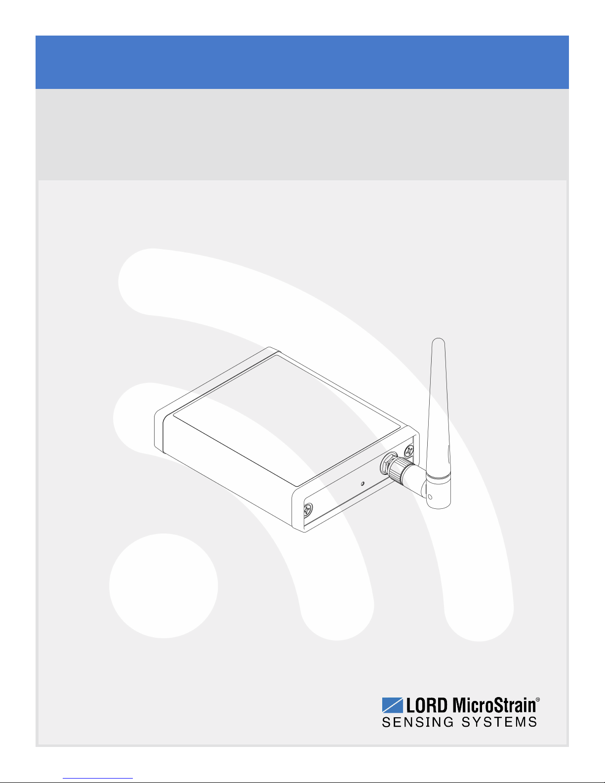
LORD USERMANUAL
WSDA®-Base-104
Wireless USBBase Station
®
Page 2
MicroStrain®Sensing Systems
459 Hurricane Lane
Suite 102
Williston, VT 05495
United States of America
Phone: 802-862-6629
Fax: 802-863-4093
http://www.microstrain.com
Copyright © 2015 LORD Corporation
3DM®, 3DM-DH®, 3DM-DH3™, 3DM-GX1®, 3DM-GX2®, 3DM-GX3®, 3DM-GX4-15™, 3DM-GX4-25™, 3DM-GX4-45™,
3DM-GX4™, 3DM-RQ1™, 3DM-GQ4™, AIFP®, AskUs How™, Bolt-Link®, DEMOD-DC®, DVRT®, DVRT-Link™, DEMOD-
DVRT®, EH-Link®, EmbedSense®, ENV-Link™, FAS-A®, G-Link®, G-Link2™, HS-Link®, IEPE-Link™, Inertia-Link®, Little
Sensors, Big Ideas.®, Live Connect™, LXRS®, MathEngine®, MicroStrain®, MVEH™, MXRS®, Node Commander®,
PVEH™, RHT-Link®, RTD-Link™, SensorCloud™, SG-Link®, Shock-Link™, Strain Wizard®, TC-Link®, Torque-Link™, V-
Link®, Watt-Link™, WirelessSimplicity, Hardwired Reliability™, and WSDA®are trademarks of LORD Corpor ation.
Document 8500-0019 Revision B
Subject to change without notice.
Page 3
WSDA®-Base-104®USBBase Station User Manual
Table of Contents
1. Wireless Sensor Network Overview 6
2. Gateway Overview 7
2.1 GatewayComponents 8
2.2 GatewayInterface 9
3. System Operational Overview 10
3.1 Software Installation 11
3.2 System Connections 12
3.3 Gateway USB Communication 13
3.4 Connect to Nodes 14
3.4.1 Adding a Node by Address 14
3.4.2 Using Node Discovery 15
3.5 Channel Configuration 16
3.6 Sampling Settings 18
3.7 Data Acquisition 19
3.8 Data Handling 24
3.8.1 Connecting to SensorCloud™ 25
3.8.2 Sensor Data Files 28
4. Gateway Communication and Settings 29
4.1 Verify Gateway Communication 30
4.2 Gateway Communication Timeout 30
4.3 Removing a Gateway 31
4.4 Gateway Information 31
4.5 Transmit Power 32
4.6 Transmit Frequency 33
Page 4
WSDA®-Base-104®USBBase Station User Manual
4.7 Monitor Mode 34
4.8 Network Broadcast 35
4.9 Using the Beacon 36
4.9.1 System Bandwidth in Synchronized Sampling 37
4.9.2 Synchronized Sampling with Multiple Gateways 37
4.10 Node Configuration and Other Settings 37
5. Gateway Installation 38
5.1 Installation Recommendations 38
5.2 Optimizing the Radio Link 39
5.2.1 Range Test 40
6. Troubleshooting 41
6.1 Troubleshooting Guide 41
6.2 Communications Ports inWindows® 46
6.3 Technical Support 48
7. Maintenance 49
8. Parts and Configurations 50
8.1 Standard Models 50
8.2 Gateway Accessories 50
8.3 Wireless System Equipment 51
8.4 Product Ordering 52
9. Specifications 53
9.1 Physical Specification 53
9.2 Operating Specifications 54
9.3 Radio Specifications 55
10. Safety Information 56
Page 5
WSDA®-Base-104®USBBase Station User Manual
10.1 ESD Sensitivity 56
10.2 Disposal and Recycling 56
11. References 57
11.1 Reference Information 57
11.2 Glossary 58
Page 6
WSDA®-Base-104®USBBase Station User Manual
1. Wireless Sensor Network Overview
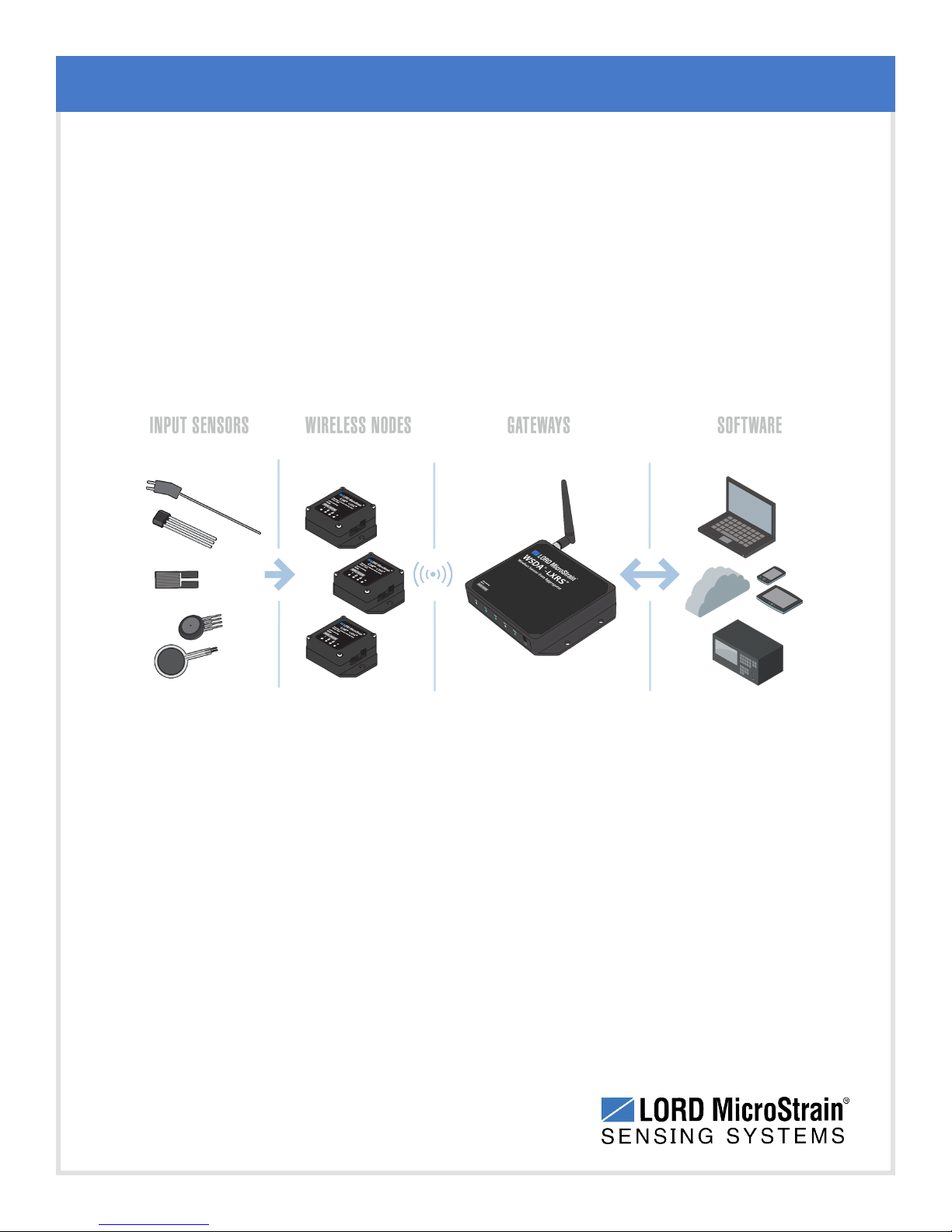
The LORD MicroStrain®Wireless Sensor Network is a high- speed, scalable, sensor data
acquisition and sensor networking system. Each system consists of wireless sensor interface
nodes, a data collection gateway, and full-featured user software platforms based on the LORD
MicroStrain®Lossless Extended Range Synchronized (LXRS®) data communications protocol.
Bidirectional wireless communication between the node and gateway enables sensor data
collection and configuration from up to two kilometers away. Gateways can be connected locally to
a host computer or remotely via local and mobile networks. Some gateways also feature analog
outputs for porting sensor data directly to standalone data acquisition equipment.
System Overview
The selection of available nodes allows interface with many types of sensors, including
accelerometers, strain gauges, pressure transducers, load cells, torque and vibration sensors,
magnetometers, 4 to 20mA sensors, thermocouples, RTD sensors, soil moisture and humidity
sensors, inclinometers, and orientation and displacement sensors. Some nodes come with
integrated sensing devices such as accelerometers. System sampling capabilities are IEEE
802.15.4-compliant and include lossless synchronized sampling, continuous and periodic burst
sampling, and data logging. A single gateway can coordinate many nodes of any type, and multiple
gateways can be managed from one computer with the Node Commander®and SensorCloud™
software platforms. Integration to customer systems can be accomplished using OEM versions of
the sensor nodes and leveraging the LORD MicroStrain®data communications protocol.
Common wireless applications of LORD MicroStrain®Sensing Systems are strain sensor
measurement, accelerometer platforms, vibration monitoring, energy monitoring, environmental
monitoring, and temperature monitoring.
6
Page 7
WSDA®-Base-104®USBBase Station User Manual
2. Gateway Overview
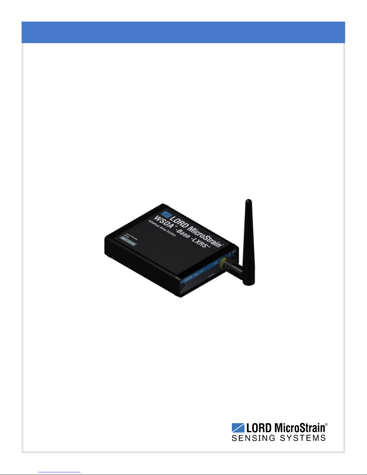
The WSDA®-Base-104®Wireless USBBase Station is a data acquisition gateway designed to
configure, co-ordinate, and collect sensor data from LORD MicroStrain®wireless sensor nodes.
The gateway supports all data acquisition sessions between wireless nodes and host computers
including: continuous sampling, burst sampling, and datalogging. The gateway also facilitates
precision sampling synchronization between sensor nodes by transmitting a continuous, systemwide timing reference known as the beacon.
The WSDA®-Base-104®utilizes a USB interface to transfer data from the wireless nodes to a
host computer for viewing, analysis, and storage.
Gateway Overview
Figure 1 - WSDA
7
®
-Base-104®USBBase Station
Page 8
WSDA®-Base-104®USBBase Station User Manual
2.1 GatewayComponents
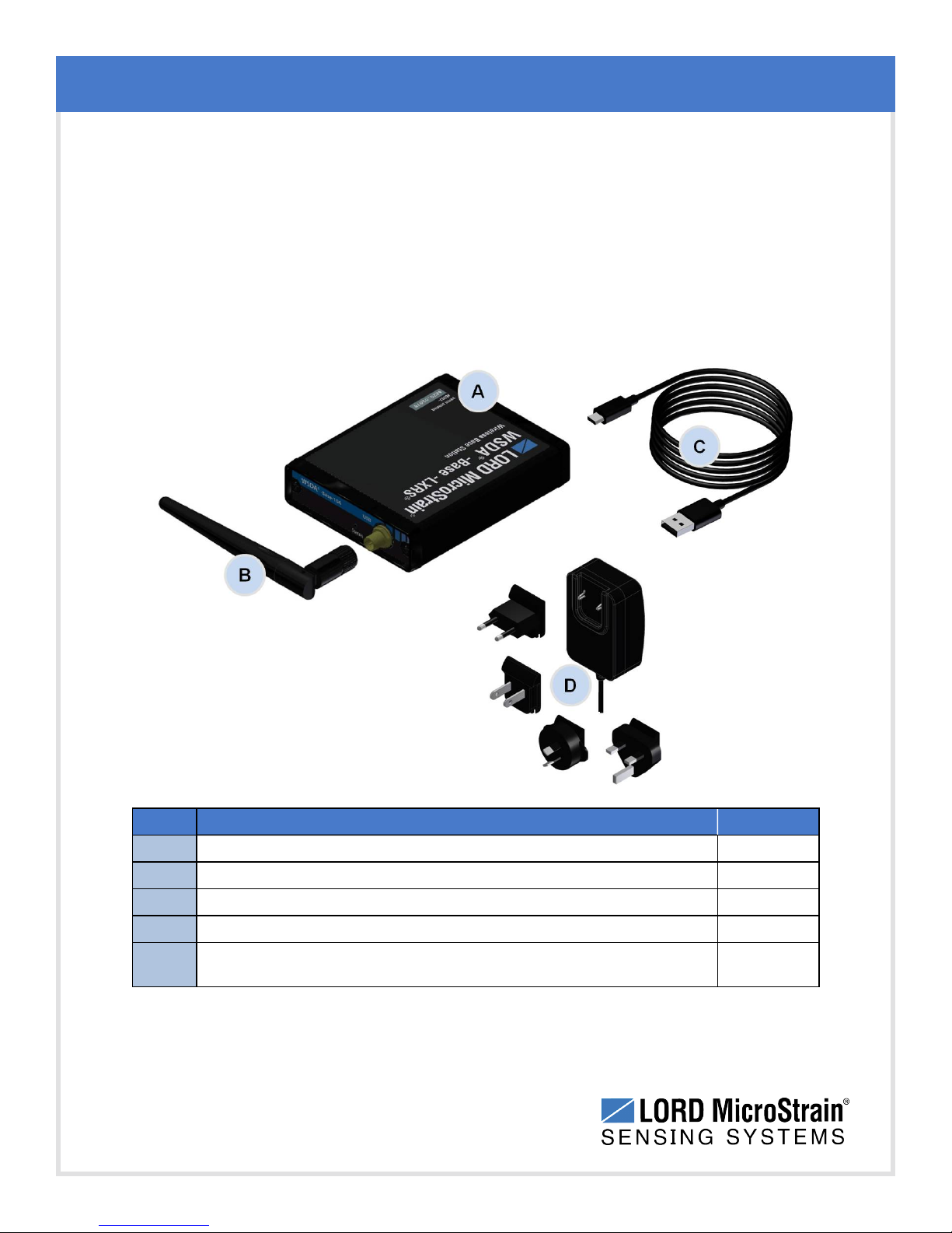
The WSDA®-Base-104®can be purchased individually or as part of a starter kit. The starter kit
includes everything required to operate the WSDA®-Base-104®including an external antenna,
a power supply for charging sensor nodes, and a USB cable for interfacing with the host
computer or network. For a complete list of available configurations, accessories, additional
system products, and ordering information see Parts and Configurations on page 50.
Gateway Overview
Item Description Quantity
A
B
C
D
--
8
WSDA®-Base-104®USBBase Station 1
Standard whip antenna (FCC compliant) 1
USB cable 1
Node power supply and plug adapter kit 1
Node Commander®Software Suite, User Manual, and Quick Start
Guide
1
Table 1 - Starter Kit Components
Page 9
WSDA®-Base-104®USBBase Station User Manual
2.2 GatewayInterface
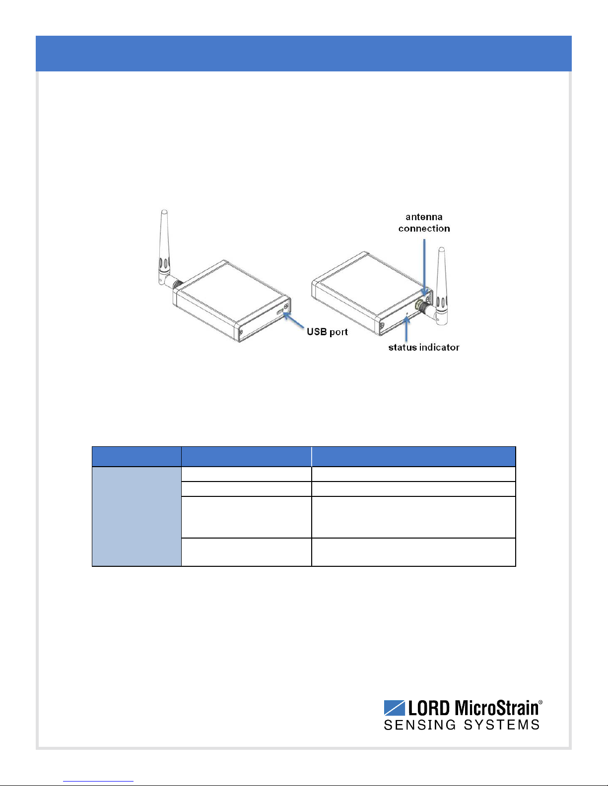
The WSDA®- Base-104®interface includes a USB portand a connector for attaching the
gateway antenna.
There are device status indicators on the front of the WSDA®-Base-104®. The following table
describes indicator behavior.
Gateway Overview
Figure 2 - Ports and Indicators
Indicator Behavior Node Status
OFF Gateway is off
ON green Gateway is powered & idle
Device Status
Indicator
Flashing blue
Flashing red
Sync sampling beacon enabled or
incoming data from other sampling
modes
WARNING: another gateway beacon
is detected on the same frequency
Table 2 - Basic Indicator Behaviors
9
Page 10
WSDA®-Base-104®USBBase Station User Manual
3. System Operational Overview
The gateway is the interface between LORD MicroStrain®sensor nodes and the data acquisition
computer.The gateway co-ordinates the configuration and sampling of the nodes and can handle
many nodes simultaneously. Communication between the nodes and gateway is wireless and
uses the LORD MicroStrain®LXRS®data communications protocol. LXRS®nodes, and many
legacy nodes, will communicate with any LXRS®gateway.
LORD MicroStrain®has two software programs available for data acquisition from the wireless
sensor network: SensorCloud™ and Node Commander®. SensorCloud™ is an optional webbased data collection, visualization, analysis, and remote management platform based on cloud
computing technology.Node Commander®is used for configuring gateways and nodes, selecting
sampling modes and parameters, initializing data acquisition, and viewing and saving data.
The operational overview describes system hardware and software setup, and the basic
navigation of Node Commander®used to configure the node and begin data acquisition. A brief
overview of porting data to SensorCloud™ is also included. This section is included as a quick start
guide and is not a complete demonstration of all system and software capabilities.
System Operational Overview
10
Page 11
WSDA®-Base-104®USBBase Station User Manual
3.1 Software Installation
To install Node Commander®Software Suite on the host computer, run the installer
executable file and follow the on-screen prompts. The software is provided with all gateways
and is available on the LORD MicroStrain®website (see References on page 57).
NOTE
The Node Commander®software includes hardware drivers required for use with
USB gateways. Once installed, the software will automatically detect and configure
any USB gateways that are plugged into the host computer.
The suite includes the following programs:
Node Commander is used for configuring nodes and acquiring, viewing, and
l
saving data.
System Operational Overview
Live Connect™is a TCP/IP-to-serial conversion tool that translates the
l
communications between Node Commander and an Ethernet gateway. This
program is only used with the WSDA®-1500 - LXRS®or other Ethernet gateways.
WSDA®Data Downloader is used to download acquired data from the flash
l
memory card embedded in an applicable gateway, to a host computer. This
program is only used with the WSDA®-1500 - LXRS®or other Ethernet gateways.
SensorCloud™ is an optional data collection, visualization, analysis, and remote
management tool. It is based on cloud computing technology and is accessed directly from a
web connection. Automatic, real- time data collection is available through Ethernet
gateways, such as the WSDA®-1500 - LXRS®. Data files can also be easily uploaded. For
more information see Data Handling on page 24.
Users can also design custom programs with the open source data communications
protocol (see References on page 57).
11
Page 12
WSDA®-Base-104®USBBase Station User Manual
3.2 System Connections
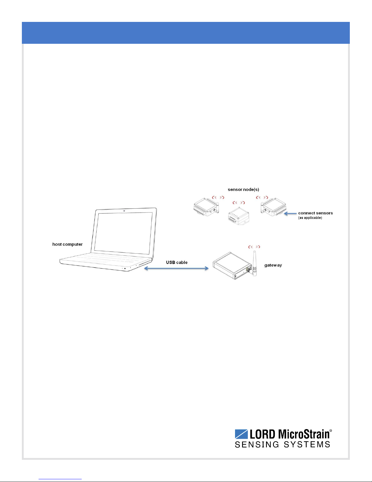
To acquire sensor data the following components are needed: user-supplied external sensors
(as applicable) , a LORD MicroStrain®wireless sensor node, a LORD MicroStrain®data
gateway and a local or networked host computer with access to the data acquisition software
(such as Node Commander®and SensorCloud™). For a connections overview refer to Figure
3 - System Connections .
The sensor, node, gateway, and software selection are application-dependent, but the basic
interfaces are the same. For a connections overview using the WSDA®-Base-104®refer to
Figure 3 - System Connections .
Users can also write custom programs by utilizing the LORD MicroStrain®Wireless Sensors
Network Software Development Kit
System Operational Overview
12
Figure 3 - System Connections
Page 13
WSDA®-Base-104®USBBase Station User Manual
3.3 Gateway USB Communication
Drivers for the USB gateways are included the Node Commander®software installation.With
the software is installed, the USB gateway will be detected automatically whenever the
gateway is plugged in.
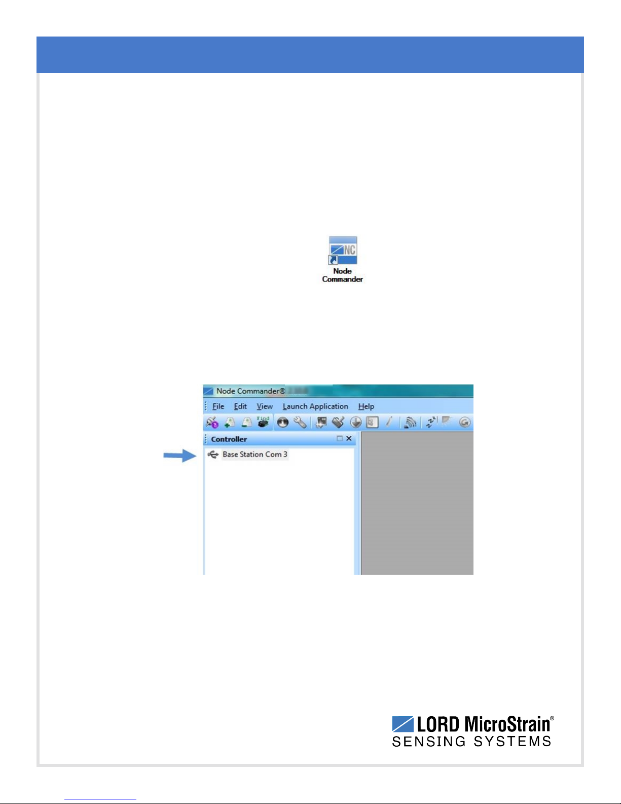
1. Power is applied to the gateway through the USB connection. Verify the gateway
status indicator is illuminated, showing the gateway is connected and on.
Open the Node Commander software.
2.
3. The gateway should appear in the Controller window automatically with a
communication port assignment (Figure 4 - USB Gateway Communication). If it is not
automatically discovered, verify the port is active on the host computer, and then
remove and re-insert the USB connector.
System Operational Overview
13
Figure 4 - USB Gateway Communication
Page 14
WSDA®-Base-104®USBBase Station User Manual
3.4 Connect to Nodes
Several methods can be used in Node Commander®to establish communication with the
nodes. This quick start section covers the two simplest methods; adding a node by address and
by using the node discovery feature.
3.4.1 Adding a Node by Address
Adding a node by address requires the node to be on the same communication frequency
as the gateway. The node address and frequency are indicated in the documentation
included with the node when it is purchased. The gateway's initial frequency setting is
indicated in the documentation that is included when it is purchased. The frequency setting
can also be checked once gateway communication is established with the host computer
(see Transmit Frequency on page 33).
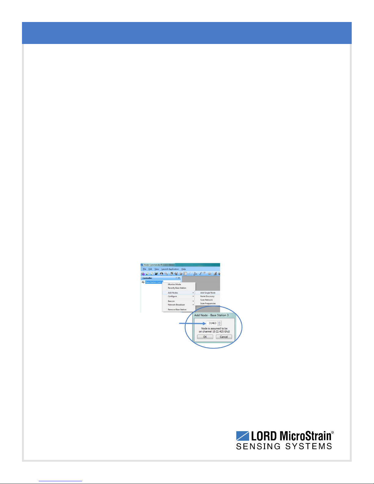
1. To add a node by address, right-click on the gateway name in the Controller window,
and select Add Node > Add Single Node (Figure 5 - Adding a Node by Address).
System Operational Overview
2. The node address and frequency are indicated in the documentation included with
the node. Enter the node address, and select OK. If the node is not found, a message
will appear and provide the option to scan for the node on other frequencies.
Alternately, the Node Discovery feature can be used.
Figure 5 - Adding a Node by Address
14
Page 15
WSDA®-Base-104®USBBase Station User Manual
3.4.2 Using Node Discovery
The Node Discovery feature allows connection between the gateway and node to occur
even if they are on different frequencies. To connect to all available nodes using node
discovery, begin by making sure the node is powered off.
NOTE
Automatic node discovery may not work in some boot-up modes. If the node is
not in normal boot up mode, the assigned one can be bypassed to enable node
discovery. For more information see Troubleshooting Guide on page 41.
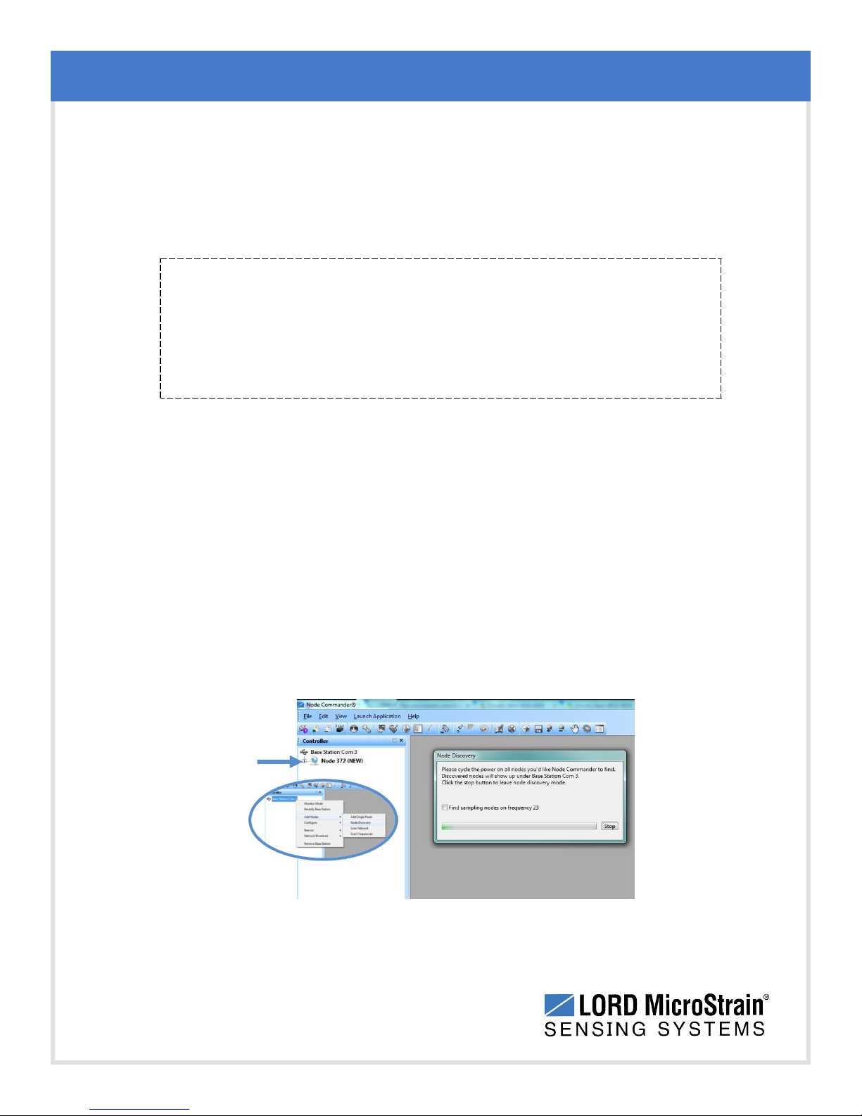
1. Right-click on the gateway name and select Add Node > Node Discovery (Figure 6 -
Using Node Discovery).
System Operational Overview
2. Using the power switch, turn on the node.Within a few seconds, the node will
transmit a message with its operating frequency.
3. When the device status indicator on the node ends the rapid flash sequence and
begins pulsing at one-second intervals, the node has completed the normal boot-up
sequence and is running in idle mode. At this point the node should be listed in the
Controller window; scanning can be stopped by selecting the Stop button in the Node
Discovery window.
15
Figure 6 - Using Node Discovery
Page 16
WSDA®-Base-104®USBBase Station User Manual
3.5 Channel Configuration
The sensor settings are stored in the node memory, and each sensor is assigned a
corresponding channel number. The configuration menus will only show the channels and
configuration options that are available for the type of node being used.
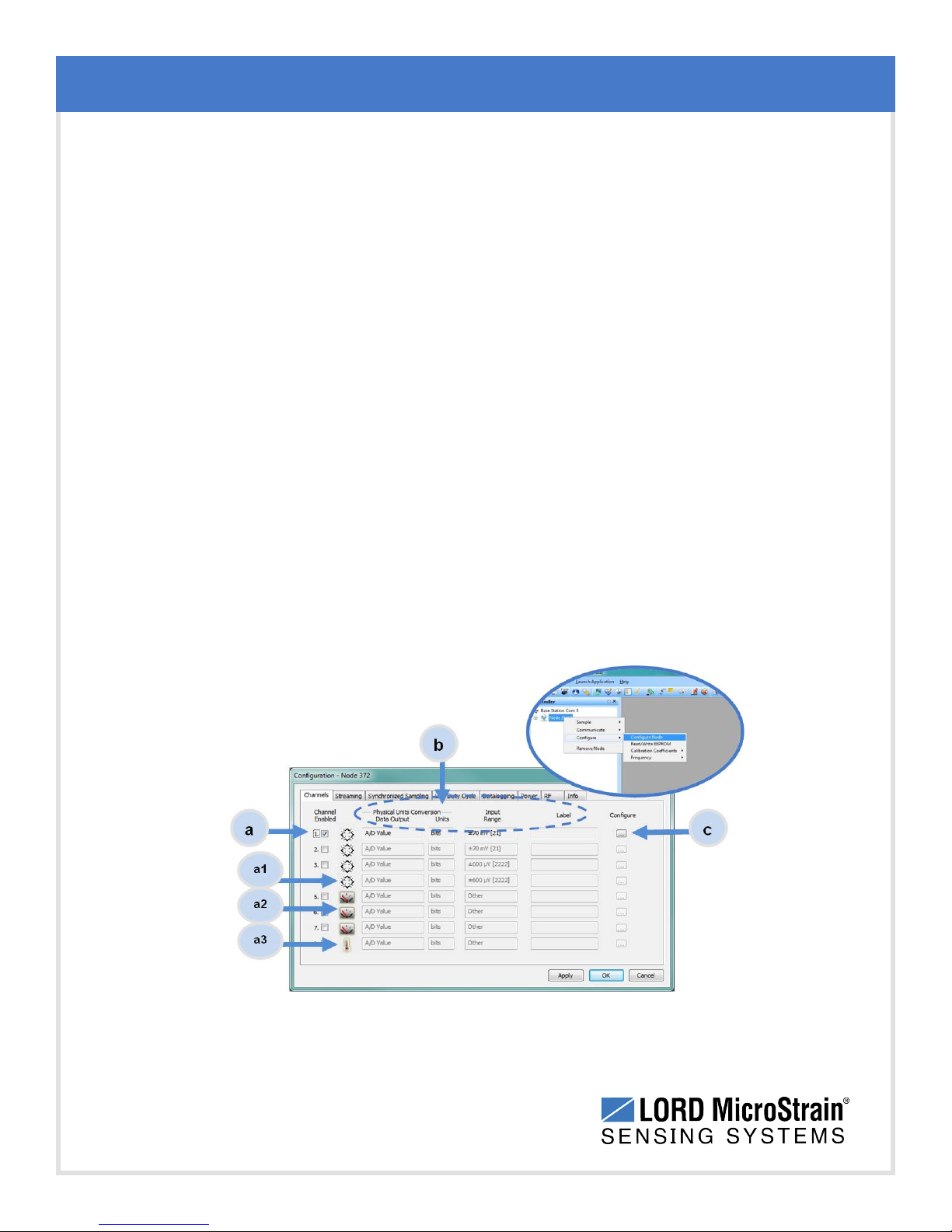
1. To enter the configuration menu, right-click on the node name, and select Configure >
Configure Node. The Channels tab displays channel options available for the node.
Channel Enabled: indicates the sensor channel number. The check box
a.
is used to enable the channel and select it for sampling. The icon next to
the check box describes the channel type inherent to the node being used.
In the following example (Figure 7 - Node Channels Menu) : a1) analog
differential channel icon, a2) analog single ended channel icon, and a3)
temperature channel icon.
Current channel configuration: The Data Output, Units, Input Range,
b.
and Label fields describe how the channel is currently configured.
System Operational Overview
Configure: The Configure button changes the channel parameters, such
c.
as measurement units, gain and offset settings, and calibration
values.The channel must be enabled first by selecting the adjacent check
box.
16
Figure 7 - Node Channels Menu
Page 17
WSDA®-Base-104®USBBase Station User Manual
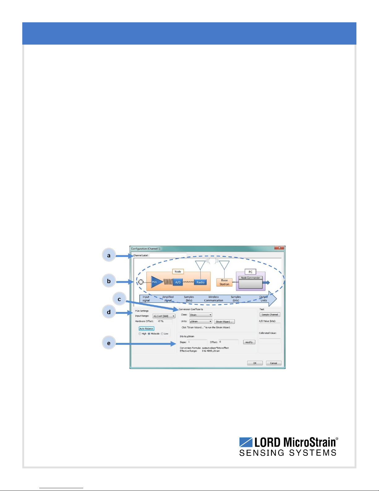
2. To enter the channel configuration menu, select the Configure button as shown in
Figure 7 - Node Channels Menu . The menu options available on the channel
configuration page varies depending on the node and sensor type selected. This is an
example with a V-Link®-LXRS®.
Channel Label: names the channel
a.
Channel diagram: shows channel electronics and data flow
b.
Conversion Coefficients: defines the type and units of the
c.
measurement being made
PGA Settings: These settings determine what gain is applied to the
d.
sensor measurement and set the position of the no- load baseline
measurement for the sensor signal. It is only available for differential input
channels with gain amplifiers.
Calibration values: includes the slope, offset, scale, and formula used to
e.
convert the sensor reading to engineering units. The slope and offset can
be determined from the sensor manufacturer calibration data or through a
calibration process.
System Operational Overview
17
Figure 8 - Channel Setup
Page 18
WSDA®-Base-104®USBBase Station User Manual
3.6 Sampling Settings
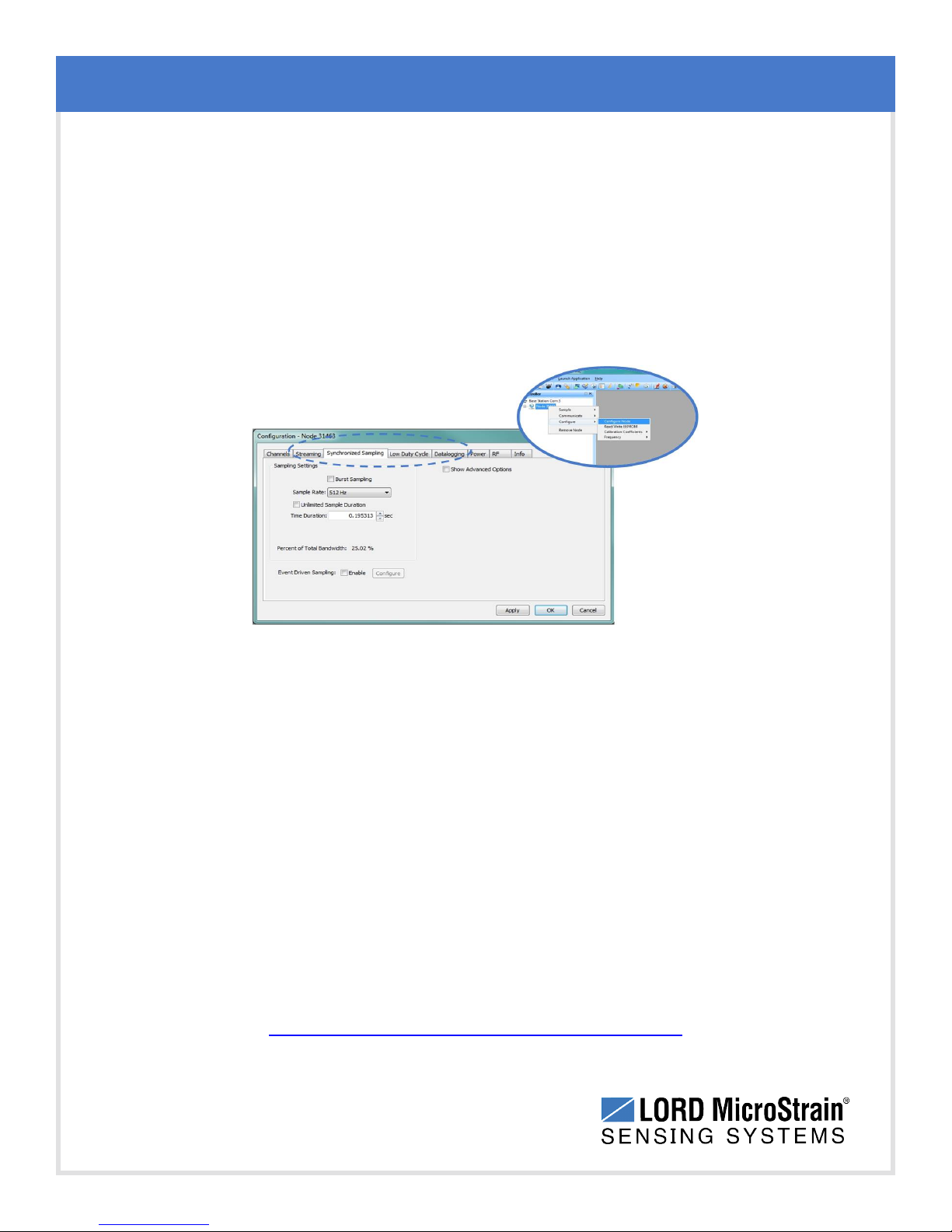
Sampling settings are accessed through the Configure Node menu. There is a tab for each
sampling mode available for the particular node (Figure 9 - Sample Settings Menu).Depending
on the type of node, up to four sampling modes are available: Synchronized Sampling, Low
Duty Cycle, Streaming, and Datalogging. Some modes have user-configurable settings for
sample rate, sample duration, and datalogging. Other settings are automatic, depending on
number of active channels and other variables. For more information on sampling modes, refer
to the Node Commander user manual (see References on page 57).
System Operational Overview
Figure 9 - Sample Settings Menu
In general, when determining what sample mode and rate is most suitable for the application,
refer to the following guidelines;
l Use a sample rate at least twice the value of the target measurement frequency. This is the
minimum sample rate required to produce an accurate digital representation of the
measured signal. The higher the sample rate, the more accurate the digital representation.
l Using the minimum required sample rate will increase battery life and minimize the
allocated network bandwidth.
l Using periodic burst sampling in place of continuous sampling will increase battery life, and
the longer the sample interval, the more power and network bandwidth will be saved.
For synchronized sampling, use the online calculator to evaluate network bandwidth at different
sampling settings :
http://www.microstrain.com/configure-your-system
18
Page 19
WSDA®-Base-104®USBBase Station User Manual
3.7 Data Acquisition
When data acquisition is started, each of the sampling modes has different menu options and
views. Some open a settings menu before data acquisition begins and may include a data list
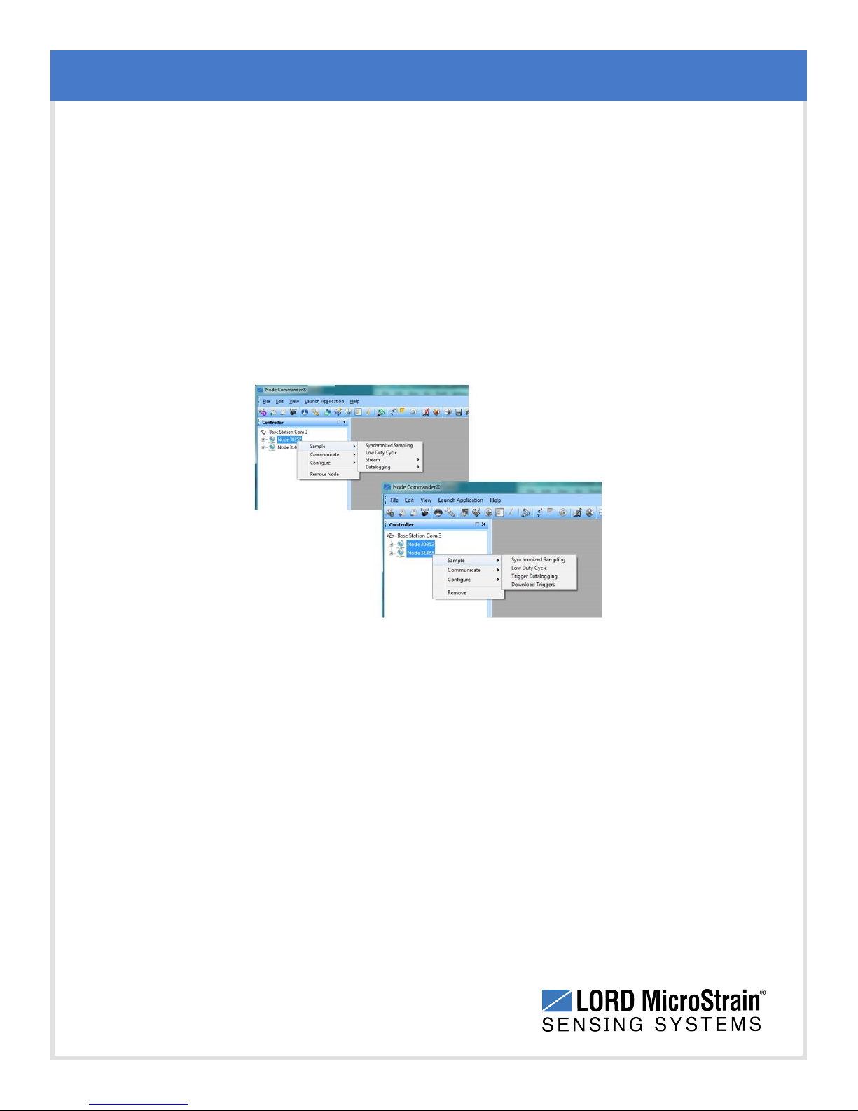
view and/or a graph view. The following is an example of Synchronized Sampling ( Figure 10 -
Starting a Sampling Session). For information on other sampling menus refer to the node user
manual or the LORD MicroStrain®website (see References on page 57).
To start a sampling session, nodes can be selected individually or as a group. When selected
as a group, they will all be set to the same sampling mode. Right-click on the nodes and select
Sample > Synchronized Sampling.
System Operational Overview
Figure 10 - Starting a Sampling Session
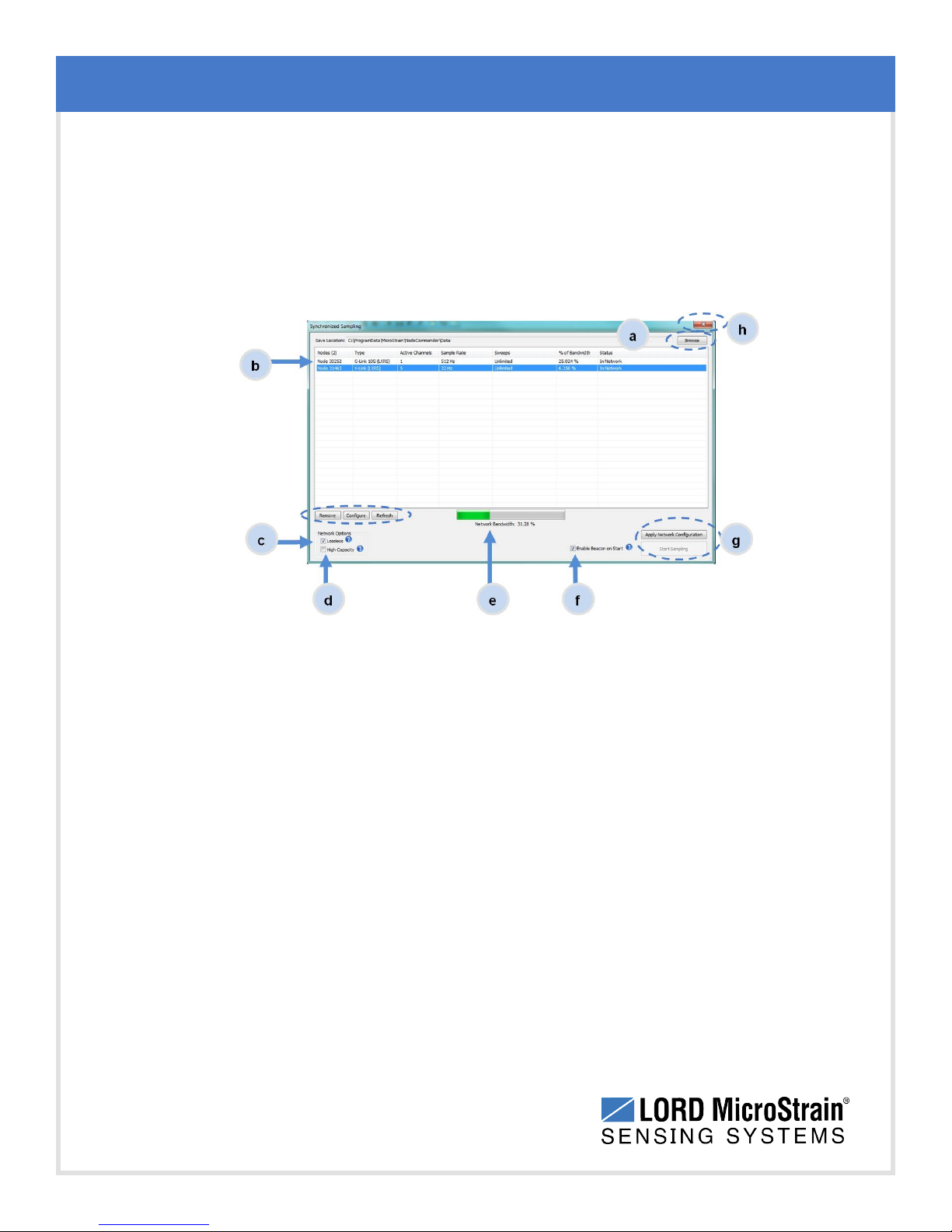
When a synchronized sampling session is started, the sampling menu appears and includes
settings to enable optional sampling features, configure nodes, and to specify where the data
will be saved. The built-in bandwidth calculator displays the total bandwidth used by the nodes
selected for synchronized sampling (Figure 11 - Synchronized Sampling Menu).
Save Location: indicates where the data file will be saved on the host computer.
a.
Use the Browse button to select a location.
Node configuration: includes the node serial number, sampling settings,
b.
bandwidth calculation, and current status. Highlight any node or group of nodes,
and the Remove, Configure, and Refresh buttons become active. The Configure
button opens the node configuration menus to adjust settings as needed and
19
Page 20
WSDA®-Base-104®USBBase Station User Manual
recalculates the node bandwidth. Multiple nodes can be configured together by
using the Shift or Ctrl key to select them.
Lossless: enables the lossless data protocol. The protocol enables buffering and
c.
retransmission of data in order to provide 100% data collection success. Using this
feature may increase data display latency.
System Operational Overview
Figure 11 - Synchronized Sampling Menu
High Capacity: optimizes bandwidth and power use for nodes with slower sample
d.
rates by reducing the transmit rates. May increase data latency.
Network Bandwidth: is the total calculated bandwidth used by all the nodes. The
e.
bandwidth changes as nodes are added, removed. and settings changed.
Enable Beacon on Start: When synchronized sampling is started the nodes wait
f.
for the first beacon transmission to initiate sampling. When this option is selected
(default), the gateway beacon is enabled and will begin transmitting at a fixed
interval when sampling is started. Disabling the beacon on start (unchecking the
box) will set the nodes to wait for the beacon, but it does not actually start the
beacon when sampling is started. This can be used if there is a need for sampling to
be initiated later, or if the beacon is being received from another source than the
gateway. Enabling the beacon in this way is the same as enabling the beacon in the
gateway menu For more information see Using the Beacon on page 36.
20
Page 21
WSDA®-Base-104®USBBase Station User Manual
Apply settings and start sampling: Before acquisition can begin, use the Apply
g.
Network Settings to save the session settings to the node. When completed, select
Start Sampling to begin.
Close sampling window (with the red "X") to exit sampling or, once the sampling
h.
has been started, to view the data window behind it.
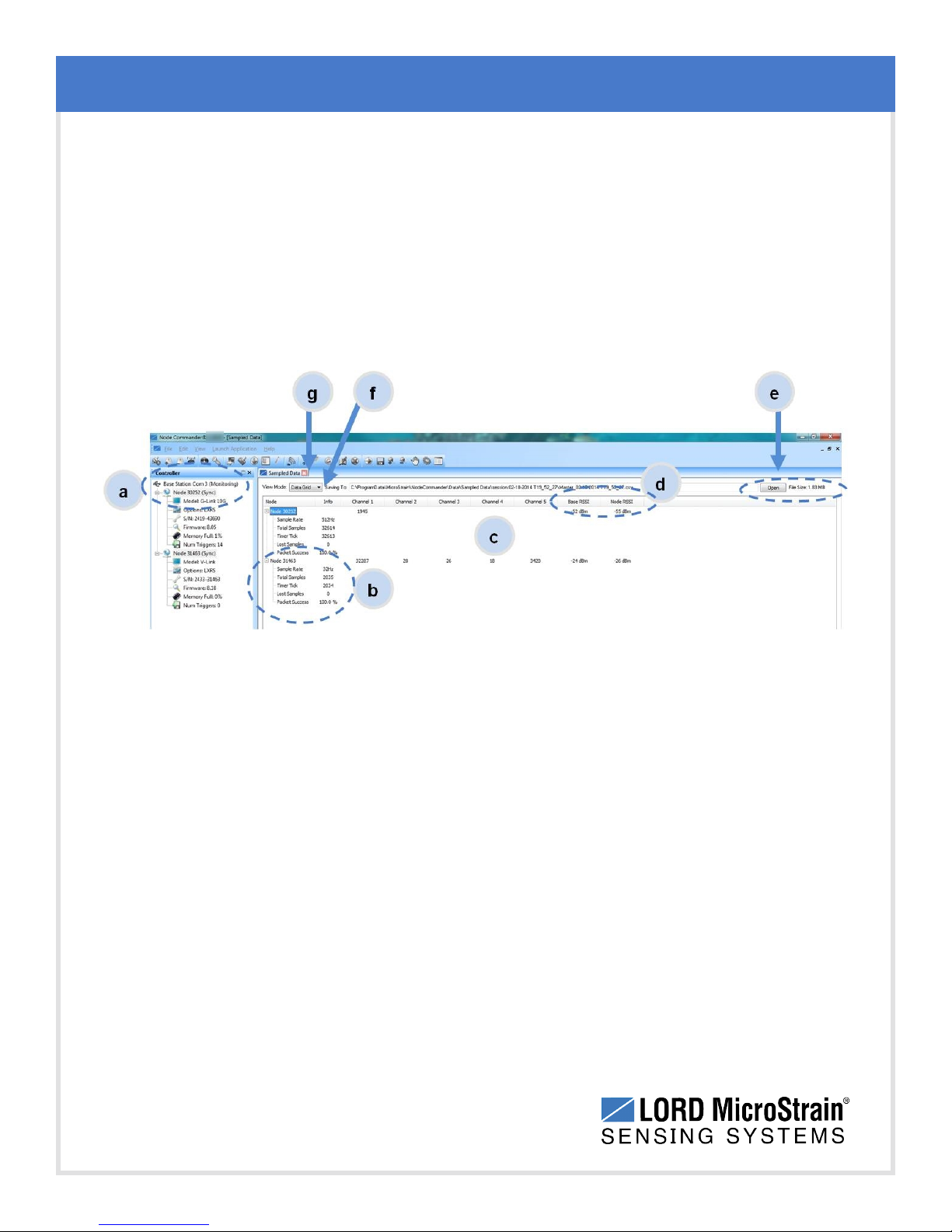
Synchronized sampling features two data views: Grid view and Graph view. Once sampling
has started, the data grid view is the default view (Figure 12 - Synchronized Sampling Data
View).
System Operational Overview
Figure 12 - Synchronized Sampling Data View
Device status: Node sampling mode and gateway status are displayed in
a.
parentheses next to the device name.
Node information: includes node serial number and sampling statistics. Right-
b.
click on the node name for more menu options such as Stop Nodes.
Data: is a display of the sampled data with each channel in its own column.
c.
Radiostrength: indicates the strength of the communication between the gateway
d.
and node. See Range Test on page 40.
Data file: the location and size of the data file, as data is added. View the data in
e.
.CSV format with the Open File button.
View menu: Select between Data Grid and Graph views.
f.
End sampling: The red "X" is used to exit the sampling window and/or end
g.
sampling.
21
Page 22
WSDA®-Base-104®USBBase Station User Manual
NOTE
When synchronized sampling is set to slower sample rates it may take several
seconds after sampling is initiated for the first sample to appear.
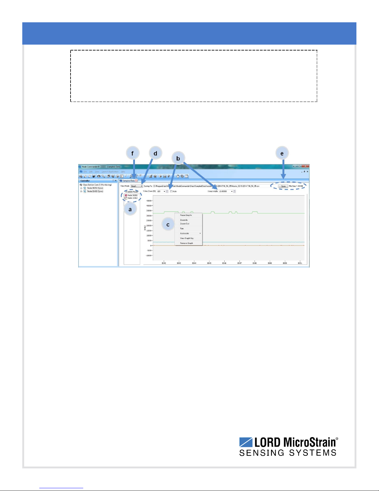
Use the view menu to select the Graph view of the data (see Synchronized Sampling Graph
View on page 22). Click on the node name to view the graph for that node. Click again to hide it.
System Operational Overview
22
Figure 13 - Synchronized Sampling Graph View
Available Nodes: Click on the node to display the graph for that node. Click again
a.
to hide it. Right-click on the node name for more menu options such as Stop Nodes
and Save Stream.
Axis range: Select the x-axis width and y-axis zoom percentage, or use the Auto
b.
check box for automatic scaling.
Graph: The node graph shows the sampled data. Each active channel is displayed
c.
in a different color. The x-axis is time in seconds and the y-axis is the A/D value
(bits). Right-click on the graph for additional menu options such as View Graph Key,
Pan, Zoom, Pause, and Remove Graph.
View menu: Select between Data Grid and Graph views.
d.
Page 23
WSDA®-Base-104®USBBase Station User Manual
Data file: The location and size of the data file as data is added. View the data in
e.
.CSV format with the Open File button.
End sampling: The red "X" is used to exit the sampling window and/or end
f.
sampling.
NOTE
Once sampling has started it will continue as configured without the need to leave
Node Commander®open. However, if the node is powered off and is not configured
to sample on boot- up, data acquisition will end and must be restarted in Node
Commander®. To resume viewing data after the sampling window has been closed,
use Monitor Mode (found in the gateway menu).
System Operational Overview
23
Page 24
WSDA®-Base-104®USBBase Station User Manual
3.8 Data Handling
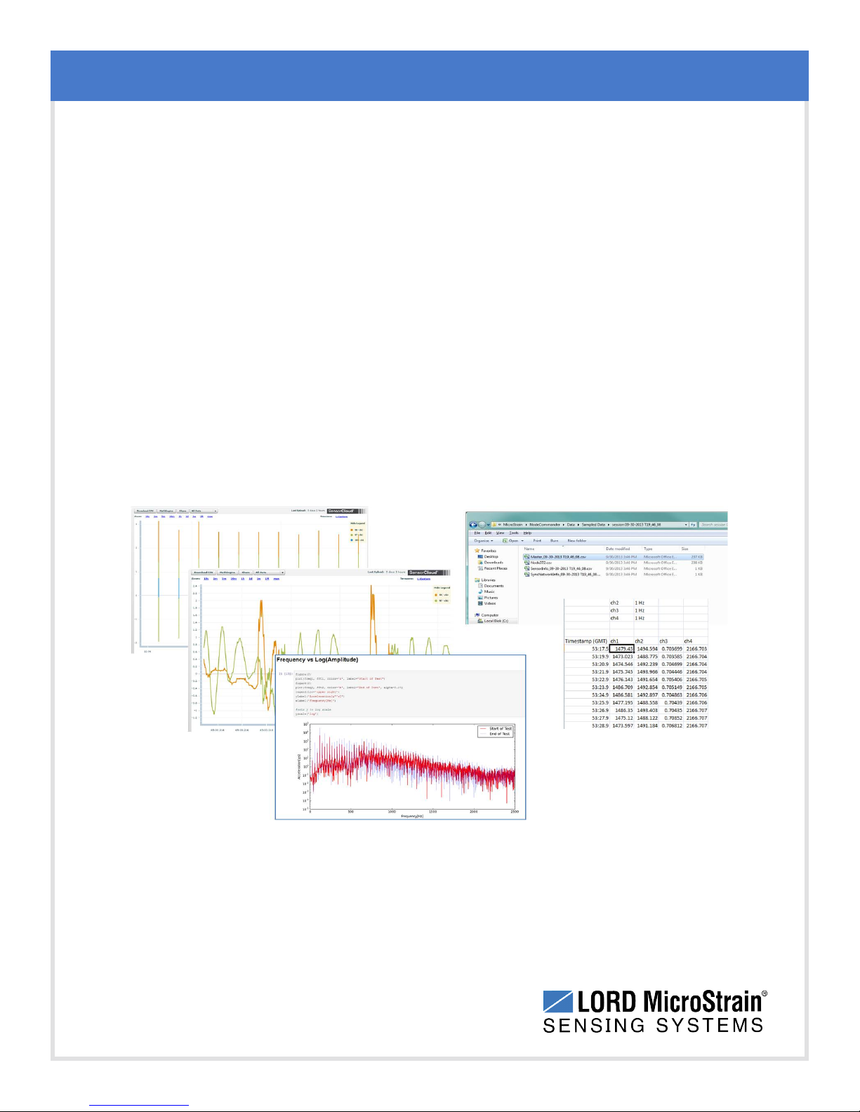
Data acquired through Node Commander®is automatically saved on the host computer (see
Sensor Data Files on page 28 ). Data can also be uploaded to the LORD
MicroStrain®SensorCloud™ web platform for display, monitoring, data storage, and analysis (
3.8 Data Handling).
SensorCloud™ is based on cloud computing technology and is designed for long term
collecting and preservation of data. Features include time series and visualization graphing,
automated alerts, and data interpretation tools such as data filtering, statistical analysis, and
advanced algorithm development with the integrated MathEngine®interface. Leveraging the
open source API, SensorCloud™ can also be used to collect data from other LORD
MicroStrain®sensor products or third- party systems. Basic SensorCloud™ services are
available to all users free of charge (see Connecting to SensorCloud™ on page 25). More
information about SensorCloud™ can be found on the LORD MicroStrain®website (see
References on page 57).
System Operational Overview
Figure 14 - Data Storage, Display and Processing
24
Page 25

WSDA®-Base-104®USBBase Station User Manual
3.8.1 Connecting to SensorCloud™
To connect to SensorCloud go to the SensorCloud website log-in page, and enter the log-in
credentials. Register as a new user if needed.
http://sensorcloud.com/log-in/
Figure 15 - SensorCloud™ Log-in or Register
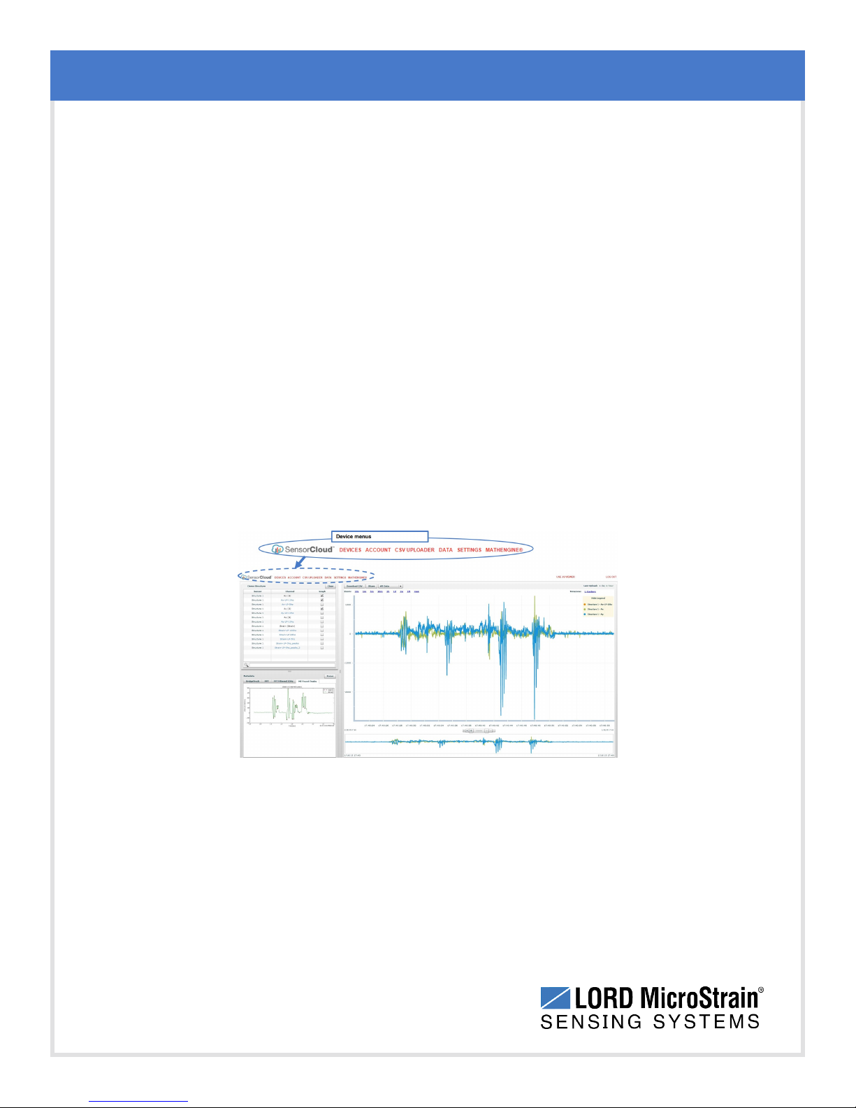
The SensorCloud interface has six main views. When logging in as a registered user, the
Device view is the default. Navigate to other views by clicking the view name at the top of the
page (Figure 16 - SensorCloud™ Menu Views). The Data and Settings views are only
available once a device is selected from the device list.
System Operational Overview
Figure 16 - SensorCloud™ Menu Views
25
Page 26
WSDA®-Base-104®USBBase Station User Manual
Device - The device list shows every Ethernet gateway and API device associated with the
SensorCloud account, including owned, shared, and demo devices. This view provides links to
each device’s SensorCloud subscription plan, configuration options, and a summary of last
communications and data transactions.
Account - The account view is for logistic management of the SensorCloud account, such as
changing the log-in password, accessing user email, and reviewing billing information.
CSVUploader - The data upload feature enables data from any source (such as non-Ethernet
LORD MicroStrain gateways, or third- party sensor) to be uploaded to the SensorCloud
platform. The data must be in the LORD MicroStrain CSV format.
Data - This view is only available after a device is selected. It displays data that is collected
from sensor nodes or uploaded from files. Data selections are listed by node channel or a userdefined label, and can be enabled for display in the graph window. The interactive graph has
navigational features such as panning, zooming, and an overview graph for single-click access
to data points or ranges. There are also use and management features such as viewing the
meta-data and downloading, embedding, and tagging data graphs.
System Operational Overview
Settings - The settings view provides options for adding meta-data, configuring the data
displays for each channel, creating alerts based on data thresholds, setting the data timezone,
and more.
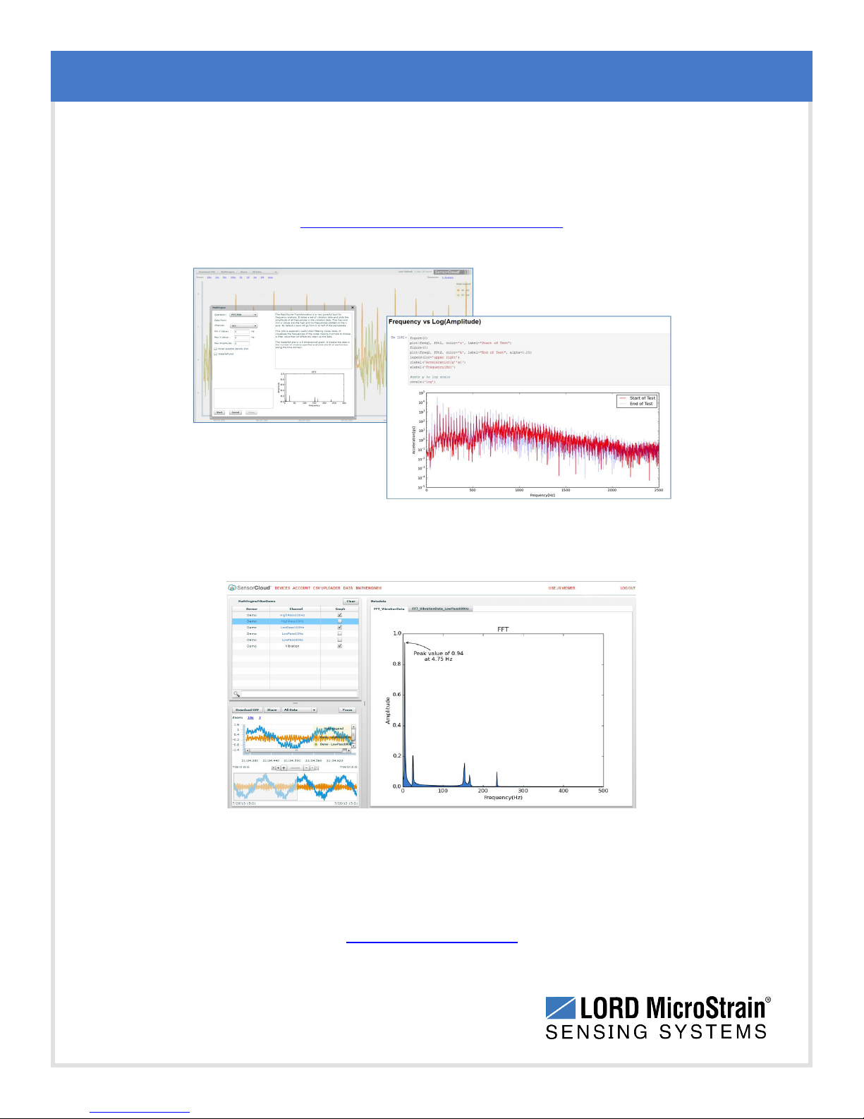
MathEngine®- is used to analyze sensor data. Functions include the ability to filter out
frequencies, smooth out noisy data, perform math operations such as Fast Fourier Transforms
26
Figure 17 - SensorCloud™ Data View
Page 27
WSDA®-Base-104®USBBase Station User Manual
(FFTs), and more ( Figure 18 - MathEngine® View ) . MathEngine®interfaces with the
SensorCloud graphing view for faster processing. Users can write their own algorithms for
custom applications. Refer to the MathEngine®website for more information.
http://sensorcloud.com/mathengine
System Operational Overview
Figure 18 - MathEngine®View
Figure 19 - FFT Graph in SensorCloud™
For more information about SensorCloud features and navigation, refer to the SensorCloud
website or contact LORD MicroStrain Technical Support.
http://sensorcloud.com
27
Page 28
WSDA®-Base-104®USBBase Station User Manual
3.8.2 Sensor Data Files
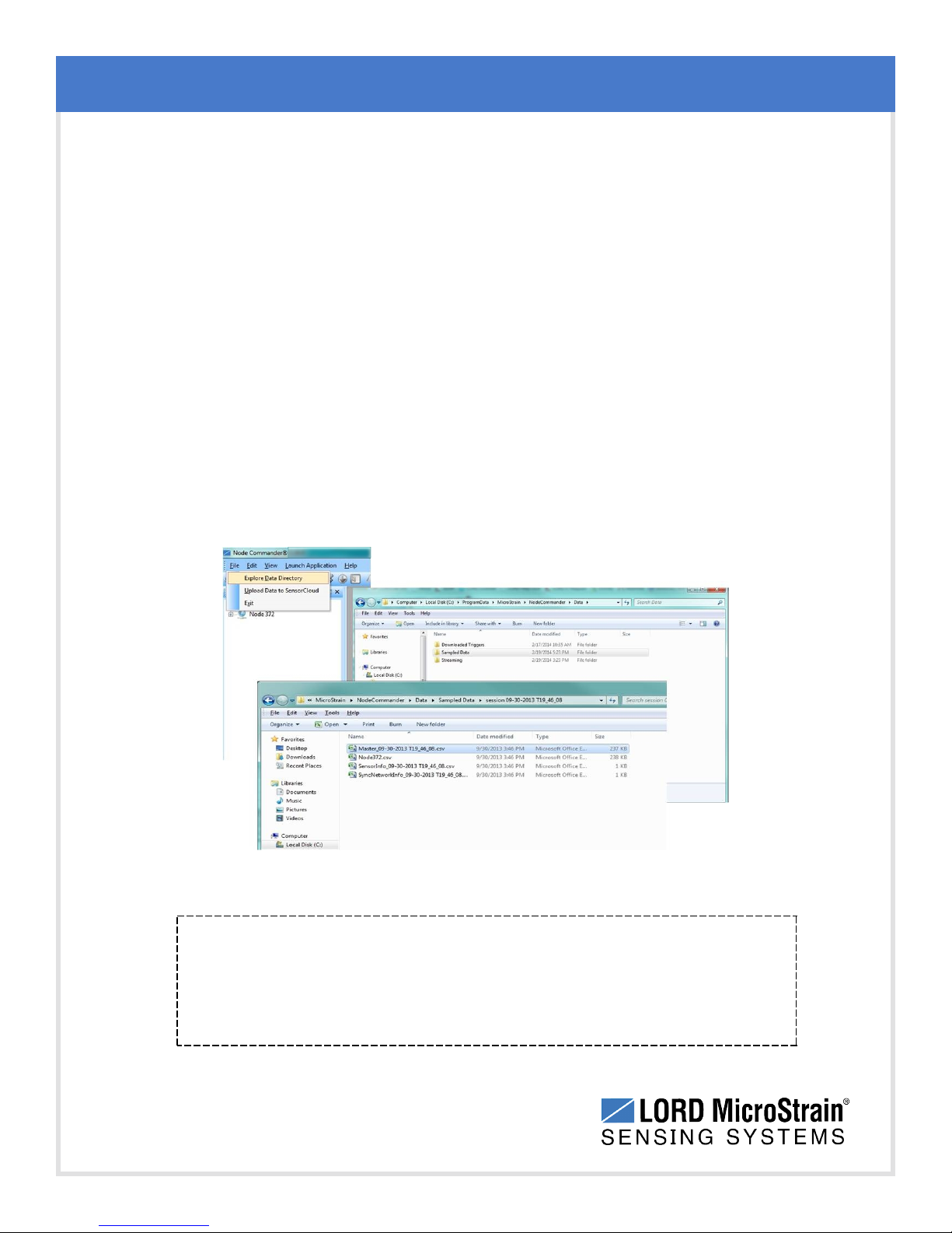
Data acquired in Node Commander is stored in .CSV format and can be opened with
Microsoft Excel, Quattro Pro, Open Office, or another CSV editors/spreadsheet program.
Data in this format is easily uploaded to SensorCloud™ using the CSV Uploader. The data
files can be found on the host computer in the default directory or the location specified at
the beginning of the sampling session (as applicable). The files are organized in separate
folders by mode and then further categorized by date, session, and/or node serial number.
The default directory is: C:\ProgramData\Microstrain\NodeCommander\Data
Synchronized sampling and low duty cycle files are found in the Sampled Data folder,
and streaming data is stored in the Streaming folder. Datalogging files need to be
downloaded from the node to be available for viewing.They are accessed through
datalogging menus as well as the File menu, and are saved in the Downloaded Triggers
folder.
System Operational Overview
The Microsoft Excel the Time data column in the data file may have to be
changed to "m/d/yyyy h:mm:ss:000" format to make it more readable.
28
Figure 20 - Exploring Data
NOTE
Page 29
WSDA®-Base-104®USBBase Station User Manual
4. Gateway Communication and Settings
Node Commander®is used to configure sensors nodes, set sampling parameters, and begin data
acquisition. This section describes how to verify communication with the gateway in Node
Commander®and adjust wireless communication settings. For detailed settings information, refer
to the Node Commander®User Manual (see References on page 57).
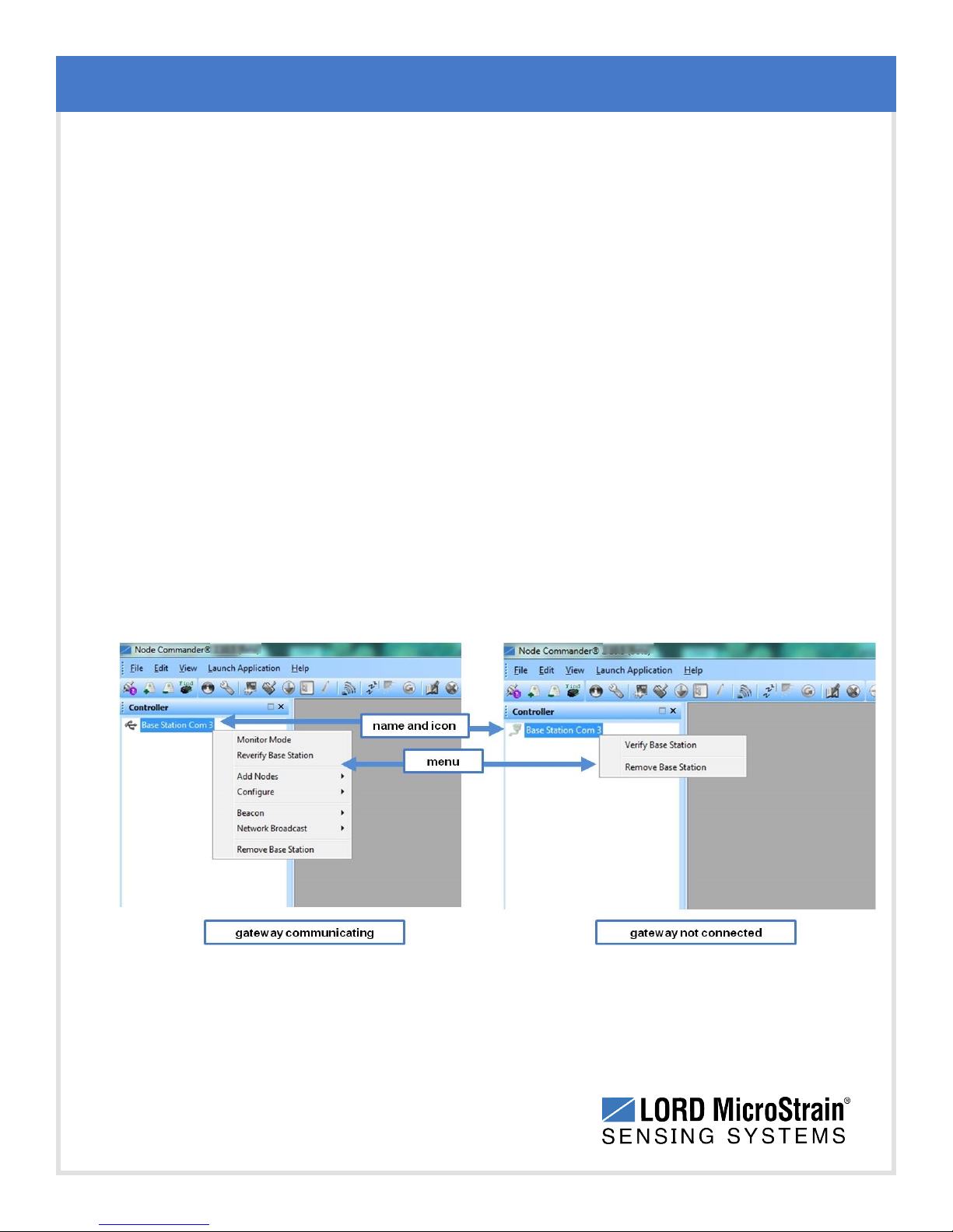
When a gateway is communicating with the host computer in Node Commander®it will appear on
a list in the Controller window with a name that includes the communications port for which it is
configured and an icon symbolizing the type of communication interface.
Node Commander®remembers gateways and nodes that have been communicated with
previously. They will appear on the list when the software is started, however the name and icon
will be grayed out if the device is not currently communicating. To remove a gateway that is no
longer used, select Remove Base Station from the gateway menu.
Right clicking on the gateway name will produce a list of menu options available for the gateway .
Figure 21 - Gateway Communication shows a USB gateway that is communicating on ComPort 3,
with the corresponding menu and a serial gateway that is not connected.
Gateway Communication and Settings
USB gateways connect automatically when plugged into the host computer.
Figure 21 - Gateway Communication
29
Page 30
WSDA®-Base-104®USBBase Station User Manual
4.1 Verify Gateway Communication
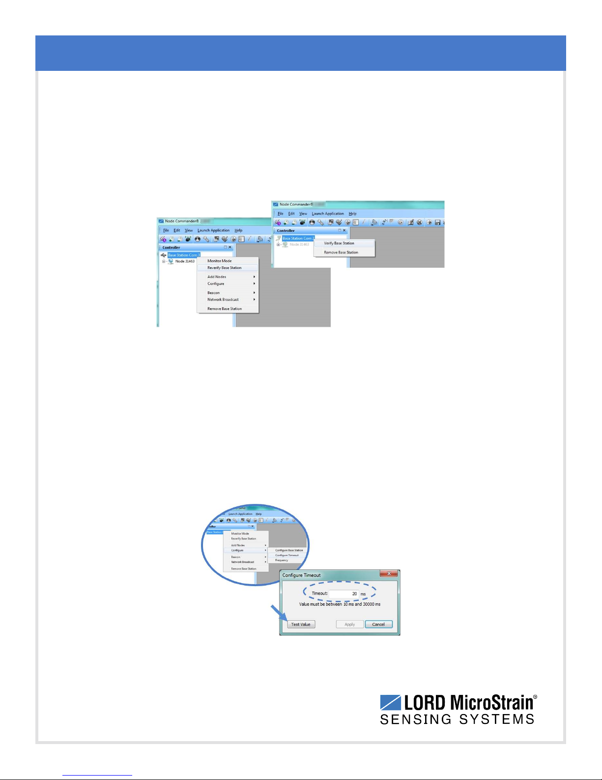
The Verify and Reverify Base Station commands can be used to check the communication
status of the gateway to the host computer. The Verify command is available in the gateway
menu if no communication has been previously established. The Reverify command is in the
gateway menu if communication has already be established, and it is used to check the current
status. Right-click on the gateway name, and select the command.
Gateway Communication and Settings
Figure 22 - Verify Gateway Communication
4.2 Gateway Communication Timeout
Node Commander®will attempt to establish communication with the gateway for the amount of
time set as the communication timeout; the default setting is 20 milliseconds. If communication
cannot be established, try adjusting this value for a longer timeout. Right-click on the gateway
name, and select Configure > Configure Timeout. Adjust the value, and then select the Test
Value button to test the communication to the gateway ( Figure 23 - Communication Timeout).
This feature can also be used if communication to the node is intermittent.
30
Figure 23 - Communication Timeout
Page 31
WSDA®-Base-104®USBBase Station User Manual
4.3 Removing a Gateway
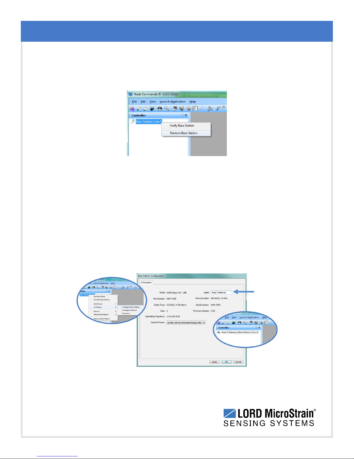
To remove a gateway that is no longer used, right-click on the gateway name in the Controller
window, and select Remove Base Station from the gateway menu .
Figure 24 - Removing Gateways
4.4 Gateway Information
Gateway Communication and Settings
Gateway information (such as the model type, serial number, radio type, operating frequency,
current communications port, and firmware revision) is found in the gateway Information
window. Right-click on the gateway name and select Configure > Configure Base Station.
There is also a Label field to give the gateway a unique name, which is useful when there are
multiple gateways in the system. Gateway transmit power can also be selected in this window.
For additional information see Transmit Power on page 32.
Figure 25 - Gateway Information and Name
31
Page 32
WSDA®-Base-104®USBBase Station User Manual
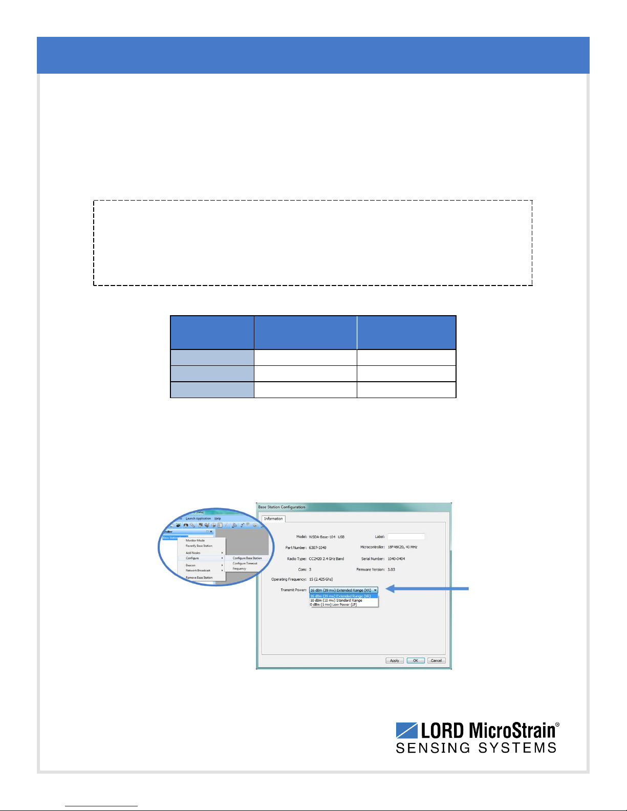
4.5 Transmit Power
The transmit power level may require adjustment if power consumption is a concern or in
regions where there are transmit power restrictions. Lowering the power output reduces power
consumption, but it also reduces the wireless communication range between the gateways and
nodes.
NOTE
Actual range is highly dependent of how the nodes and gateways are installed and the
conditions in the surrounding environment (see Range Test on page 40).
Gateway Communication and Settings
Setting Power Output
Extended
Standard
Low
16 dBm (39mW) 2 km
10dBm (10mW) 1 km
0dBm (1mW) 70 m
Maximum
Range
Table 3 - Transmit Power Settings
The transmit power setting for the gateway is found in the gateway Configure Base Station
menu.
32
Figure 26 - Transmit Power Setting
Page 33
WSDA®-Base-104®USBBase Station User Manual
4.6 Transmit Frequency
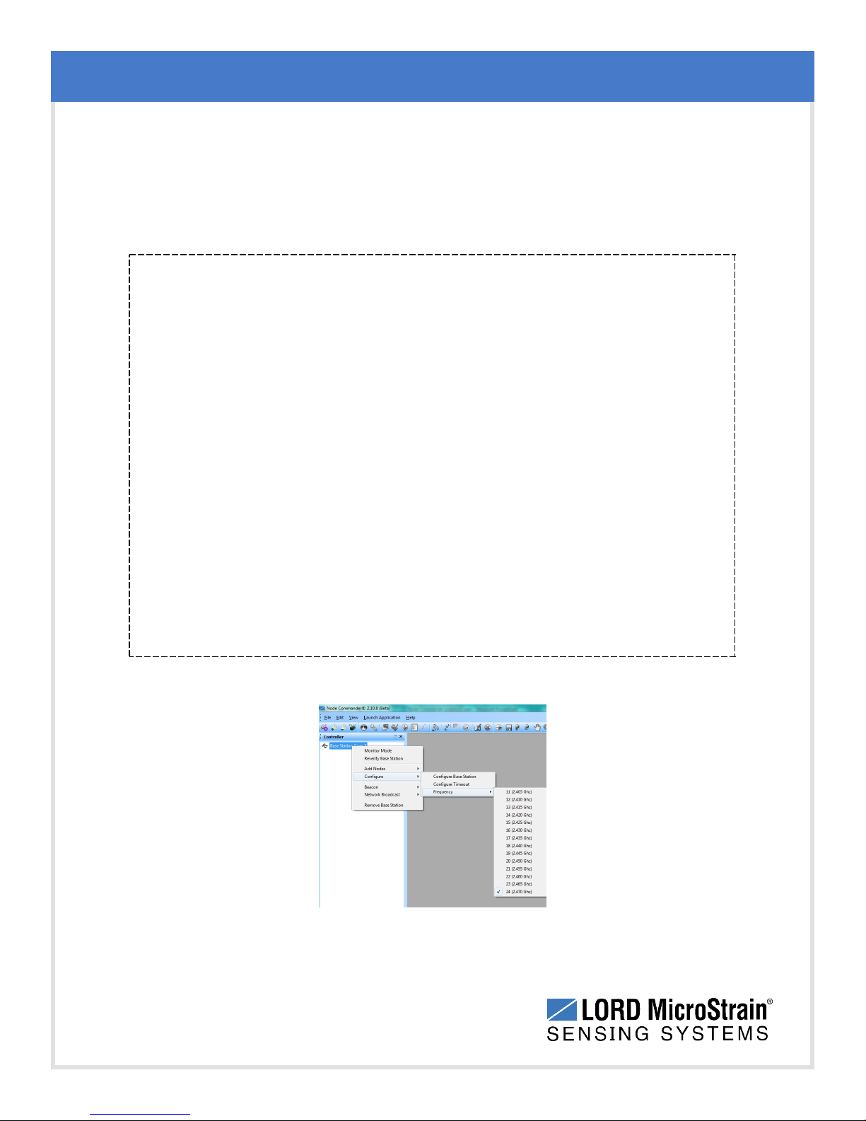
The transmit frequency of the wireless sensor network refers to the communication link
between the gateway and the node. There are 14 available frequency channels between 2.405
and 2.470 GHz.
NOTE
l The gateway can automatically manage nodes operating on different frequencies
by using the Node Discovery feature in Node Commander®. In this routine, the
gateway listens for node broadcasts on the frequency channel to which it is set. If
the node is in normal boot-up mode, it will provide the broadcast when it is initially
powered-on, and it will broadcast on all channels. As long as the node is poweredon after activating the Node Discovery feature, the gateway will link to it and
remember the channel setting for future node queries.
l Manually matching the node and gateway frequency channels is required in some
applications. For example, when sending broadcast messages from the gateway to
multiple nodes (including the synchronized sampling beacon) all nodes must be on
the same channel as the gateway in order to receive the broadcast. Assigning
channels is also a good idea when multiple gateways are attached to one host
computer or when other wireless equipment is nearby and frequency or
transmission interference may occur.
Gateway Communication and Settings
The frequency setting for the gateway can be changed from the Configure menu.
Figure 27 - Gateway Frequency
33
Page 34
WSDA®-Base-104®USBBase Station User Manual
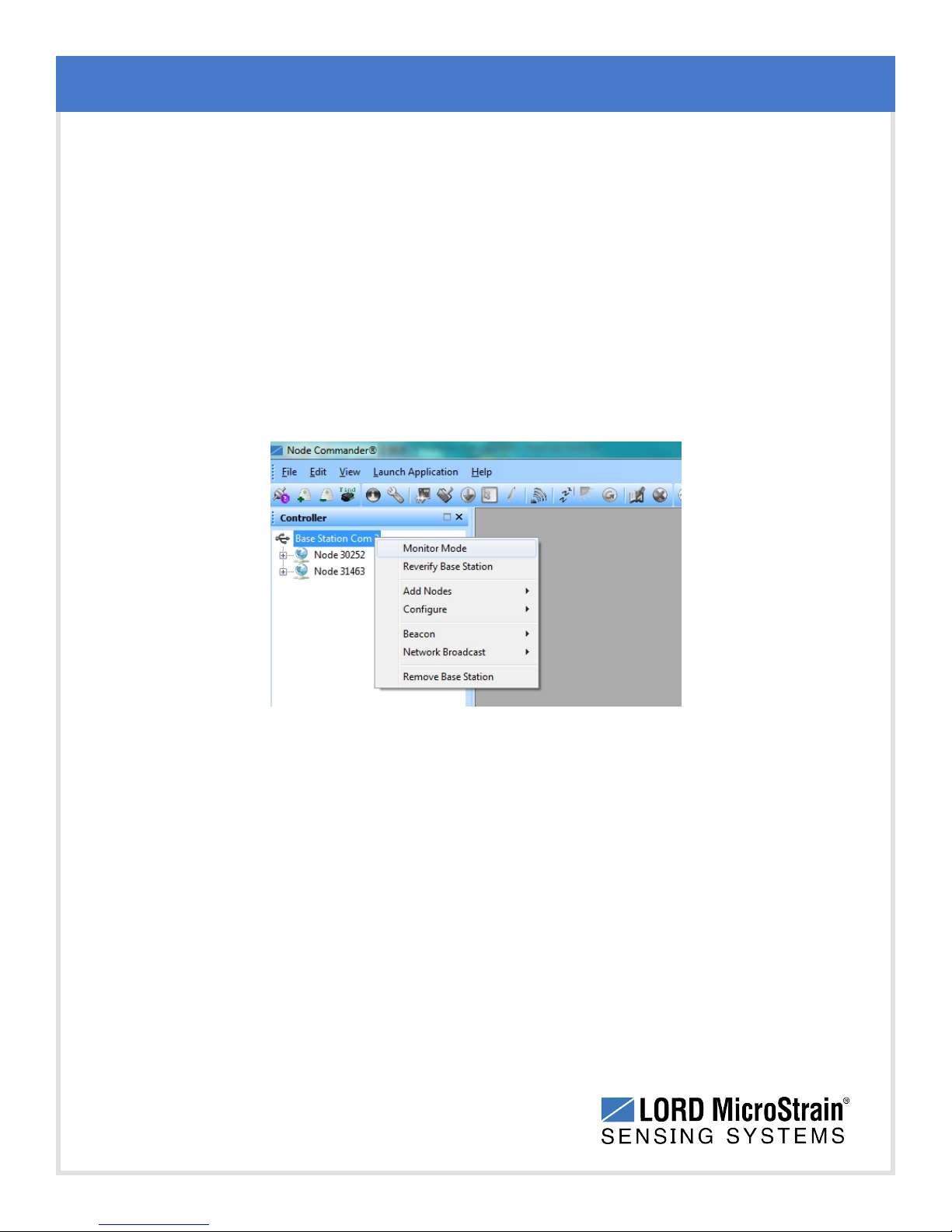
4.7 Monitor Mode
Monitor mode is used to observe any low duty cycle and synchronized sampling activity that is
occurring on nodes connected to a particular gateway. When monitor mode is selected, the
sampling window opens and displays the data. This is useful if the node was configured to start
sampling on boot up or if the data acquisition screen was closed without stopping the node. It is
a way to enter the data and graph view windows after data acquisition has already begun. The
gateway will only monitor nodes that are on the same frequency (channel) that it is on. All
nodes on that frequency will automatically be displayed.
To monitor a node, right click on the gateway name and select Monitor Mode.
Gateway Communication and Settings
34
Figure 28 - Monitor Mode
Page 35
WSDA®-Base-104®USBBase Station User Manual
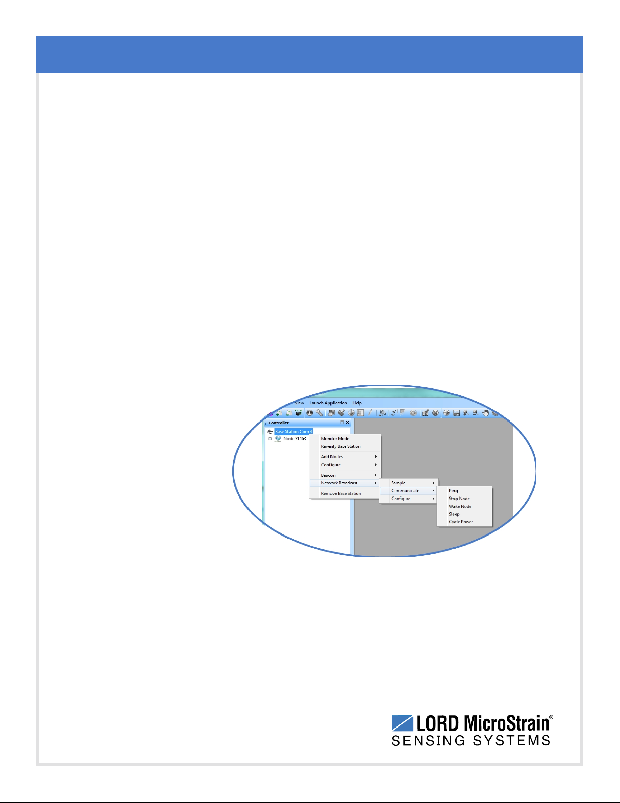
4.8 Network Broadcast
The network broadcast feature is used to send the same command at the same time to multiple
nodes connected to the same gateway. Nodes must be on the same transmission frequency
(channel) as the gateway to receive broadcast commands. Network broadcast functions
include communications, sampling, and configuration commands.
Network broadcast commands are found in the gateway menu. Right click on the gateway
name, and select Network Broadcast. Then select the desired category and command.
Sample
l Synchronized Sampling Start
l Low Duty Cycle Start
l Armed Datalogging
l Trigger Datalogging Session
Gateway Communication and Settings
l Erase
Communicate
l Ping
l Stop Node
l Wake Node
l Sleep
l Cycle Power
Configure
l Read/Write EEPROM
Figure 29 - Network Broadcast Commands
35
Page 36
WSDA®-Base-104®USBBase Station User Manual
4.9 Using the Beacon
In synchronized sampling, the beacon feature is used to coordinate sampling and
transmission timing between multiple nodes. The primary purpose is to avoid data collision,
guarantee timing between samples from different nodes, and to time-stamp the data. The
beacon cannot be used in any another sampling mode.
When the beacon is enabled, the gateway broadcasts a data message once every second
containing a Coordinated Universal Time (UTC) time stamp, and it is used to update each
node’s real time clock (RTC). This continuous synchronization beacon, coupled with the
accuracy of the gateway and node clocks (+/- 3 ppm drift), provides a node- to- node
synchronization within +/-32 microseconds. The gateway receives the UTC from the host
computer, so the host must be connected to a UTC time server to achieve that accuracy.
There is some lag inherent in the Microsoft Windows distribution of the UTC. This dictates
the overall accuracy of the time-stamp, but the synchronization times between the gateway
and nodes will be consistent because of the accuracy of the embedded RTC clocks.
Gateway Communication and Settings
Nodes must be on the same transmission frequency (channel) as the gateway to receive the
beacon broadcast command. When the beacon is active, the gateway device status
indicator will pulse blue once per second. When the nodes connected to the gateway are in
synchronized sampling mode, the network can be put to sleep by turning off the beacon and
then resuming transmitting once the beacon is enabled. Any node that is actively sampling in
synchronized sampling mode on the same frequency as the gateway will synchronize to it
automatically if the beacon is activated.
To avoid interference with other devices it is recommended that the beacon be disabled
when not in use. Do not operate multiple gateways on the same frequency.
To enable and disable the beacon, right click on the gateway name and select the
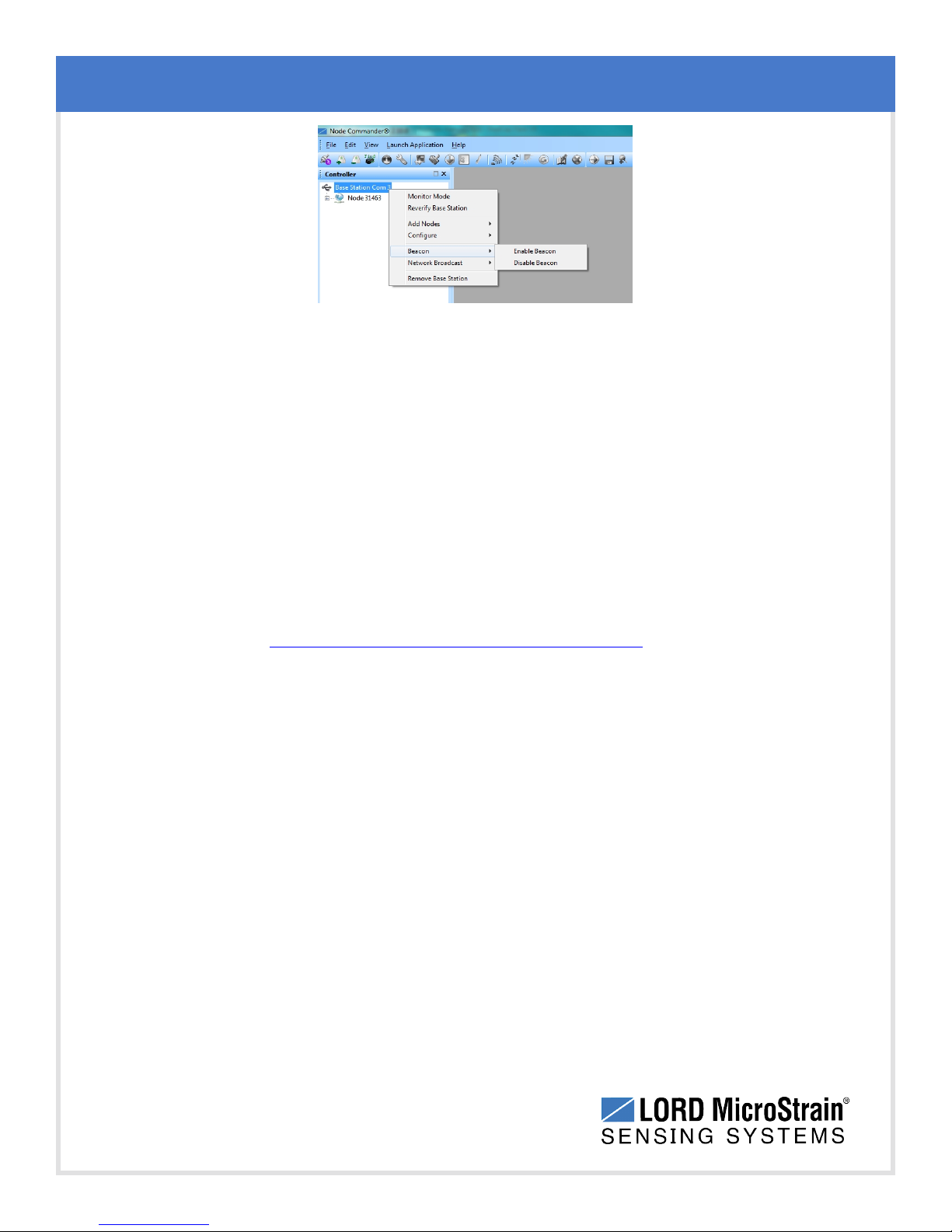
appropriate command ( Figure 30 - Synchronized Sampling Beacon) . Alternately, the
beacon can be activated from the synchronized sampling window when sampling is started,
and stopped with the stop node command which can be executed when sampling is ended
(see Data Acquisition on page 19 and refer to the Node Commander®User Manual for
more information ).
36
Page 37
WSDA®-Base-104®USBBase Station User Manual
Figure 30 - Synchronized Sampling Beacon
4.9.1 System Bandwidth in Synchronized Sampling
When using synchronized sampling all nodes in the wireless network are queried and given
time slots of various lengths based on their configuration (# of channels, sample rate, etc.).
Nodes will only transmit data during these time slots, therefore eliminating over-the-air data
collisions. The total time available for node transmissions is defined by the system
bandwidth. Because the system bandwidth is finite, only a fixed number of nodes can be
supported when using synchronized sampling. The number of nodes is largely dependent
on node configuration, as each consumes part of the bandwidth. Use the online network
bandwidth calculator to determine the bandwidth capacity for a particular system
configuration: http://www.microstrain.com/configure-your-system
Gateway Communication and Settings
4.9.2 Synchronized Sampling with Multiple Gateways
If synchronization is desired between gateways, it is recommended that a WSDA®-1500 LXRS®gateway be used because they can be configured to reference external time
sources and therefore get periodic same time updates. WSDA®- Base - 10x - LXRS
gateways do not have this feature and instead rely on the internal clock (which can vary
between gateways). For more information refer to the WSDA®-1500 - LXRS®User
Manual.
4.10 Node Configuration and Other Settings
Node configuration is completed exclusively in Node Commander®. For an overview of sensor
configuration and menus see Connect to Nodes on page 14.
For additional node configuration and gateway settings not discussed in this manual, refer to
the Node Commander®user manual (see Reference Information on page 57).
37
®
Page 38
WSDA®-Base-104®USBBase Station User Manual
5. Gateway Installation
5.1 Installation Recommendations
The WSDA®-Base-104®is rated for indoor use only, unless housed in a ruggedized outdoor
enclosure (purchased separately).It is designed for desktop use, although it can be mounted in
any orientation as required by the application. It is recommended that it is mounted in a way that
optimizes the wireless communications, typically with the antenna pointing upward. For more
information see Optimizing the Radio Link on page 39.
Gateway Installation
38
Figure 31 - Gateway Installation
Page 39
WSDA®-Base-104®USBBase Station User Manual
5.2 Optimizing the Radio Link
In ideal conditions, the nodes and gateway can communicate up to two kilometers apart. In
order to accomplish this, the node and gateway must be installed in a manner that optimizes the
wireless transmission.The WSDA®-Base-104®operates at a 2.4GHz transmission frequency
and comes standard with a right-angle, ¼-wave rubber whip antenna with an omni-directional
radiation pattern. Using any other antenna than the one that is included with the node will void
FCC compliance.
The best method for ensuring optimal radio communication is to conduct an RF survey of the
installation site. This is easily accomplished in Node Commander®by using the range test
feature to quantify the radio signal strength (RSSI) in various scenarios. See Range Test on
page 40 for instructions on using Node Commander®for measuring RSSI. The following are
general guidelines for maximizing transmission range:
Establish Line of Sight (LOS) between the node and gateway antennas as best
l
as possible. Try to avoid obstructions between the antennas, such as buildings,
terrain, vegetation, or other physical barriers. Increase the mounting height of the
node or antenna to allow a clearer LOS path to the gateway. Height above the
ground is also important because reflections off of the ground can interfere at the
receiver. Generally, the higher above the ground the better.
Gateway Installation
39
Minimize Radio Frequency Interference (RFI) such as other equipment
l
antennas, especially those operating in the same frequency range. This includes
other nodes. If other antennas are required nearby, mount them at different
heights to minimize interference. Additionally, the specific node frequency is
selectable within its operational range using the Node Commander®software. Set
the devices to different transmission frequencies.
Minimize Electromagnetic Interference (EMI) such as that which is generated
l
by power transmission equipment, microwaves, power supplies, and other
electromagnetic sources.
Metal Objects in close proximity to either antenna, particularly ferrous metals
l
such as steel and iron, can be problematic for wireless communications. The
larger the object, the greater the influence.
Page 40
WSDA®-Base-104®USBBase Station User Manual
5.2.1 Range Test
After establishing communication between node and gateway, use the range test feature in
Node Commander®to monitor the signal strength and to optimally position the nodes,
gateway, and antennas for installation. Maximum achievable range is determined by the
gateway and node power settings (found in the device Configure menu) and is highly
dependent on the physical environment surrounding the devices.
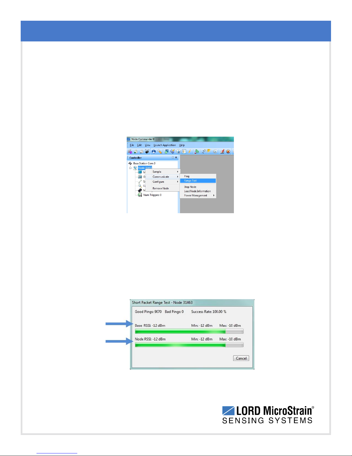
1. Right-click on the node header, and select Communicate > Range Test.
Gateway Installation
Figure 32 - Range Test Menu
2. The total RSSI range for the node and gateway is - 90 to 0dBm. The higher
the value (closer to zero), the better, but reliable communication can be
achieved between - 75 dBm and 0 dBm. The devices is still able to
communicate between -90 dBm and -75 dBm, but it could be intermittent or
result in data loss. Position the node and gateway antennas where the best
RSSI value is observed.
Figure 33 - Range Test Statistics
40
Page 41
WSDA®-Base-104®USBBase Station User Manual
6. Troubleshooting
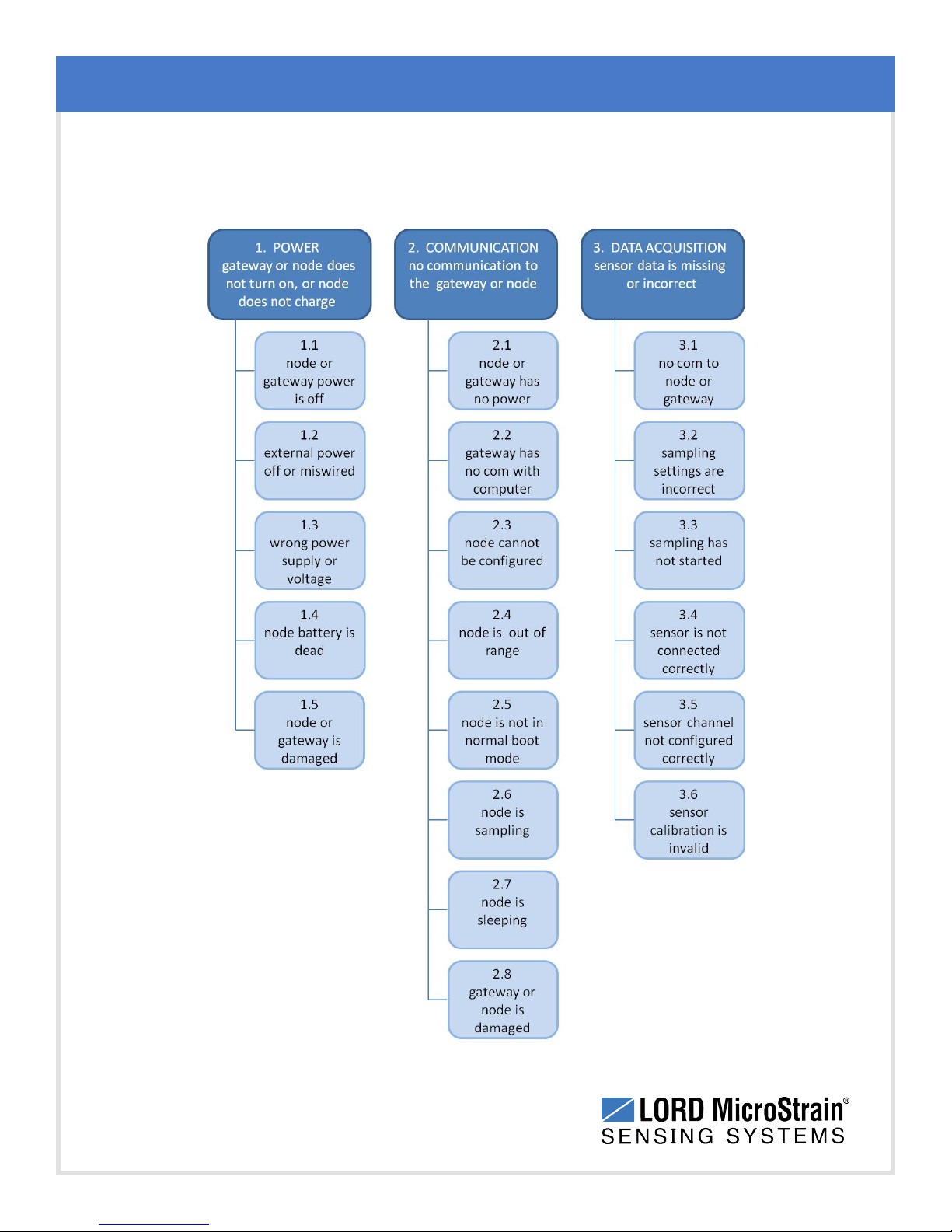
6.1 Troubleshooting Guide
Troubleshooting
41
Page 42
WSDA®-Base-104®USBBase Station User Manual
Problem Possible cause and recommended solution
1.1 node or gateway power is off
Troubleshooting
1. POWER
gateway or node does
not turn on
The status indicator LED on the device may be off. Turn the
device on, and the status indicator LED should illuminate.
1.2 external power is off or miswired
Verify the device power source is connected correctly and
powered on.
1.3 wrong power supply
Using a power supply other than the one specified for the device
(or an external supply that is outside of the device operating
range) could result in permanent damage to the device or cause
it to not work properly.
1.4 node battery is dead
If the node will not power on, the node battery may need to be
replaced. Contact LORD MicroStrain®Technical Support ( See
Technical Support on page 48).
1.5 node or gateway is damaged
If all power settings and connections have been verified, and the
node is still unresponsive, contact LORD MicroStrain
®
Technical Support (See Technical Support on page 48).
2. COMMUNICATION
no communication to
the gateway or node
42
2.1 node or gateway has no power
Verify the node and gateway have power applied and that
applicable power switches are on. Power is indicated on both
devices by a status indicator LED.
2.2 gateway has no communication with the computer
Verify gateway communication in the software. Check, remove,
and reconnect communications and power cables as applicable.
l For serial gateways, verify that the COM port setting.
l For USBgateways, verify that the drivers are installed on the
computer (included with Node Commander®) and that the
software has had sufficient time to detect it.
Page 43
WSDA®-Base-104®USBBase Station User Manual
Problem Possible cause and recommended solution
Troubleshooting
l For Ethernet gateways, use Live Connect
™
to verify
communications on a DHCPnetwork. Check that the
extended timeouts are enabled in the Node Commander
®
Edit > Preferences menu, under Devices. Once
communication has been established, the network
configuration can be changed.
2.3 node cannot be configured
Observe the node status indicator LED to determine the
device's state: boot, idle, sample, or sleep. If the node is
sampling or sleeping, it cannot be configured. In Node
Commander®, execute the Stop Node command to put the
node in idle state, allowing configuration to occur.
If the user inactivity timeout is set very low, the configuration
menu will have to be entered quickly, before the timeout occurs,
putting the node back in a sample or sleep state.
2.4 node is out of range
Perform a bench test with the node in close proximity to the
gateway to verify they are operational. For range test and
installation recommendations see Range Test on page 40. The
system has been tested to operate with the node and gateway
up to 2 km apart with clear line of sight.
43
2.5 node is not in normal boot mode
If the node status indicator shows the node booting in a mode
other than the normal boot mode, it can be bypassed by toggling
the node ON/OFF switch rapidly three times, then leaving it in
the ON position for normal power up. In normal boot mode the
communication can be established with automatic node
discovery (or manually) once the boot process is complete and
the node is in idle state. Start-up mode can then be changed in
the software.
2.6 node is sampling
Observe the node status indicator LED to determine the
device's state: boot, idle, sample, or sleep. If the node is
sampling, it cannot be configured. In Node Commander®,
Page 44
WSDA®-Base-104®USBBase Station User Manual
Problem Possible cause and recommended solution
execute the Stop Node command to put the node in idle state,
allowing configuration to occur.
2.7 node is sleeping
Observe the node status indicator LED to determine what state
it is: boot, idle, sample, or sleep. If the node is sleeping, it cannot
be configured. In Node Commander®, execute the Stop Node
command to put the node in idle state, allowing configuration to
occur.
2.8 gateway or node is damaged
Verify all connections, power, and settings. If available, try
installing alternate nodes and gateways one at a time to see if
the faulty device can be identified. If no conclusion can be
determined or to send a device in for repair, contact LORD
MicroStrain®Technical Support ( See Technical Support on
page 48).
Troubleshooting
3. DATAACQUISITION
sensor data is missing
or incorrect
3.1 no communication to node or gateway
Verify connections and power to the node and gateway. Verify
they are powered on and communicating with the software.
Enter a configuration menu to verify that the node can be
accessed.
3.2 sampling settings are incorrect
If the sampling mode, rate, or duration are not performing as
expected, enter the node configuration menu, and verify the
sampling settings.
3.3 sampling has not started
If sampling is occurring, the sampling mode will be displayed
next to the node name in Node Commander®. The node device
status indicator will also be flashing the sampling mode code. If
the node is not sampling, activate it in the software or with a
sample on start up boot sequence.
3.4 sensor channel not configured correctly
Verify that the sensor is configured on the correct channel and
has been enabled for data acquisition.
44
Page 45
WSDA®-Base-104®USBBase Station User Manual
Problem Possible cause and recommended solution
3. sensor calibration is invalid
External sensors come with a factory calibration value that is
entered during configuration. Internal sensors are factory
calibrated and should not need adjustment. The calibration data
is provided with the sensor when purchased.If possible, perform
a field verification of the sensors by applying known loads and
comparing the measured values. In the channel configuration
settings, verify that the calibration calculations are correct.
Verify that the gain and offset range are correct and that the
baseline offset is set with Auto Balance, as applicable. Verify
that the calibration values (slope and offset) are correct. Verify
that the sensor channel units are selected correctly. Verify that
all parameters were written to the node channel. Recalibrate as
needed.
Troubleshooting
45
Page 46
WSDA®-Base-104®USBBase Station User Manual
Troubleshooting
6.2 Communications Ports inWindows
®
Serial gateways (including USB gateways) have either a standard serial or virtual
communications port in Windows®. Windows®Device Manage can be used to determine what
communication port the gateway is connected to.
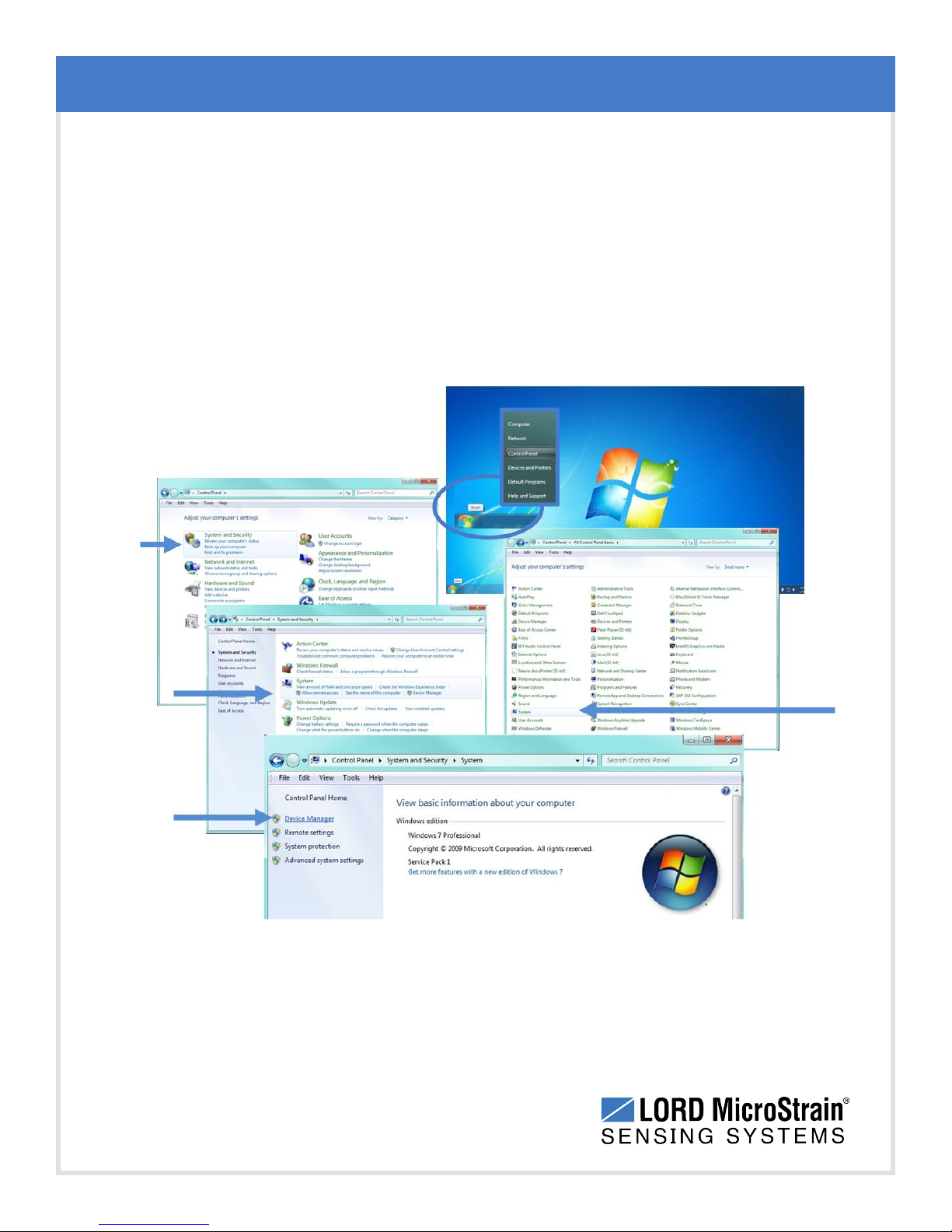
1. Click on the Windows®Start icon, and select Control Panel.
2. Navigate to the System menu, and select Device Manger. The menus may appear
different depending on the version of Windows and the View settings.
46
Figure 34 - Windows
®
System Menu
Page 47
WSDA®-Base-104®USBBase Station User Manual
3. In Device Manager, expand the view for Ports (COM and LPT). Active COM ports will
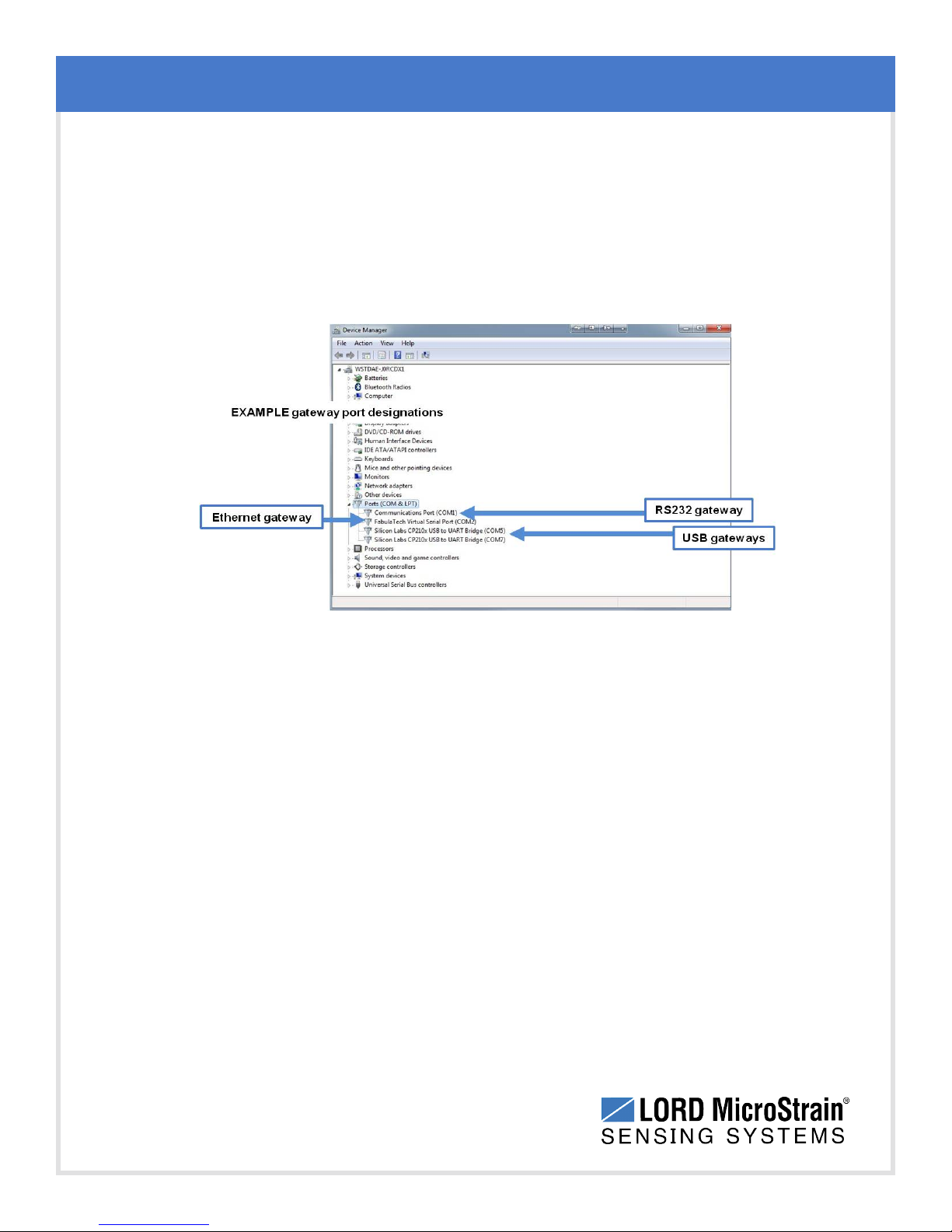
appear on this list with the COM port number. A USB gateway will be displayed as
USB to UART Bridge (COM X ). A serial gateway will be attached to the
Communications Port (COMX). An Ethernet gateway will be connected to a Virtual
Serial port (COMX). If no port is listed, the port is not recognized by the computer, and
no gateway communication can be established.
Troubleshooting
Figure 35 - Windows®Device Manger Menu
47
Page 48
WSDA®-Base-104®USBBase Station User Manual
6.3 Technical Support
There are many resources for product support found on the LORD MicroStrain®website,
including technical notes, FAQs, and product manuals.
http://www.microstrain.com/support_overview.aspx
For further assistance our technical support engineers are available to help with technical and
applications questions.
Technical Support
Phone: 802-862-6629
Fax: 802-863-4093
SKYPE: microstrain.wireless.support
Troubleshooting
Live Chat is available from the website during business hours:
9:00 AM to 5:00 PM (Eastern Time US & Canada)
48
Page 49
WSDA®-Base-104®USBBase Station User Manual
7. Maintenance
There are no user-serviceable parts on the WSDA®-Base-104®. For device service and repair
contact LORD MicroStrain®Technical Support (see Technical Support on page 48). Opening the
device will void the product warranty.
Maintenance
49
Page 50
WSDA®-Base-104®USBBase Station User Manual
8. Parts and Configurations
8.1 Standard Models
For the most current standard, custom, and OEM product options, refer to the LORD
MicroStrain®website or contact the LORD MicroStrain®Sales Department.
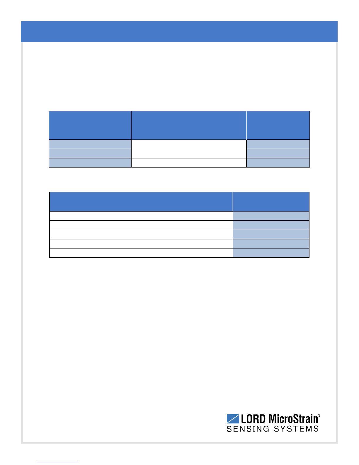
Model Number Description
WSDA-Base-104-LXRS
WSDA-Base-102-LXRS
WSDA-Base-101-LXRS
8.2 Gateway Accessories
Wireless USB Base Station
Wireless RS232 Base Station
Wireless Analog Base Station
Parts and Configurations
LORD
MicroStrain
®
Part Number
6307-1040
6307-1020
6307-1010
Description
Standard whip antenna (FCC compliant)
USB cable, Micro-B, 1 meter long
Node charging power supply
Node power supply international plug adapters
Node Commander®software flash drive
Table 4 - Gateway Accessories
LORD MicroStrain
Part Number
9010-0049
9022-0029
9011-0024
9011-0009
8200-0021
®
50
Page 51
WSDA®-Base-104®USBBase Station User Manual
8.3 Wireless System Equipment
The following system parts are available for use with the WSDA®-Base-104®. For the most
current standard, custom, and OEM product options, refer to the LORD MicroStrain®website
or contact the LORD MicroStrain®Sales Department. See Product Ordering on page 52.
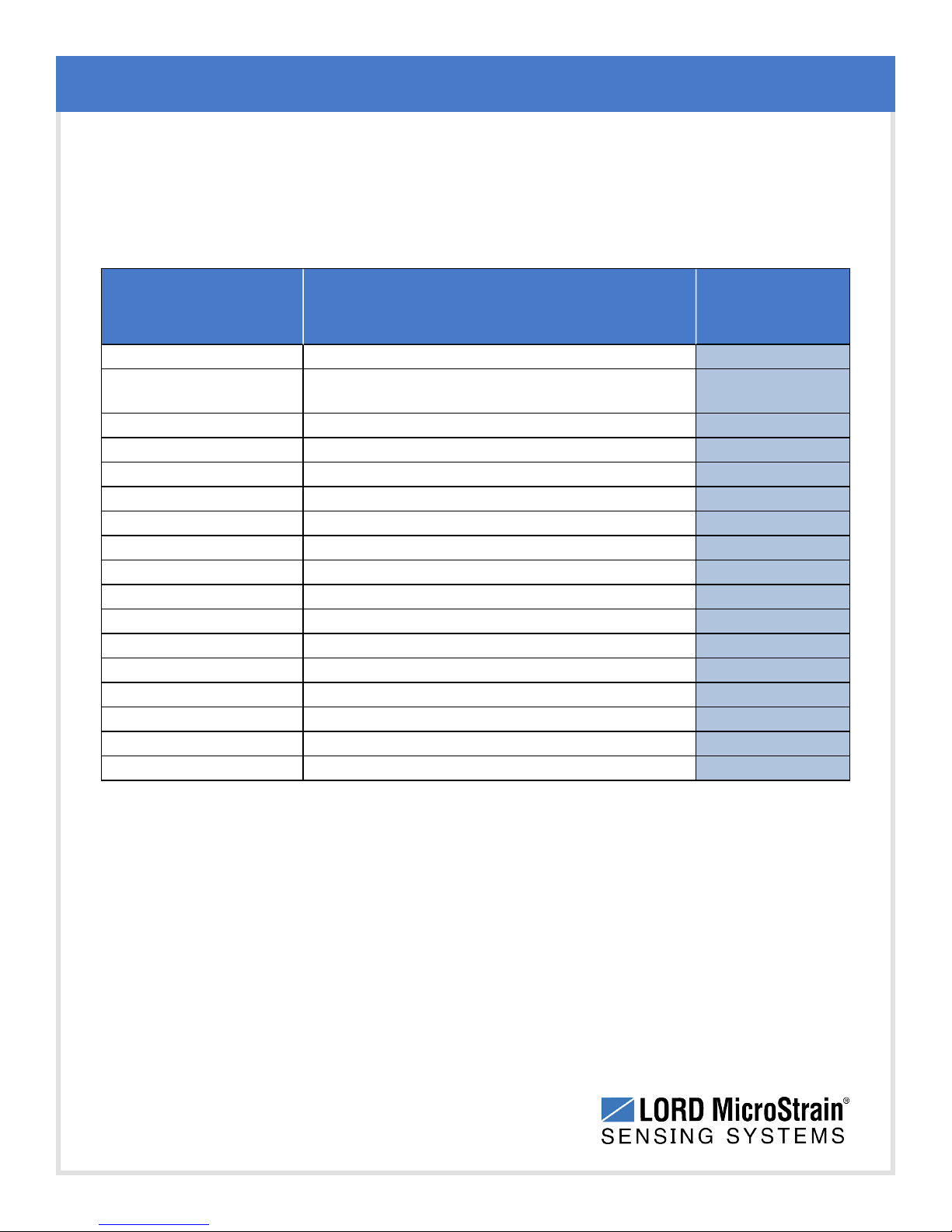
Model Description
-- Node Commander®Software
--
WSDA-1500 Ethernet Data Gateway
WSDA-BASE-102 RS232 Serial Output Gateway
WSDA-BASE-101 Analog Output Gateway
G-Link-LXRS Wireless Accelerometer Node
G-Link2-LXRS Wireless Accelerometer Node
SG-Link-LXRS Wireless 2-Channel Analog Input Sensor Node
SG-Link-OEM Wireless 2-Channel Analog Input Sensor Node
SG-Link-RGD Ruggedized Wireless Analog Sensor Input Node
V-Link-LXRS Wireless 7-Channel Analog Input Sensor Node
TC-Link-LXRS Wireless Thermocouple Node
DVRT-Link-LXRS Wireless Displacement Sensor Node
ENV-Link-Pro Wireless Environmental Sensor Node
Watt-Link-LXRS Wireless Energy Monitoring Sensor Node
RTD-Link-LXRS Wireless RTD Sensor Node
IEPE-Link -LXRS Wireless IEPEAccelerometer Node
SensorCloud™ Software Subscription
(contact LORD MicroStrain®Sales)
Parts and Configurations
LORD
MicroStrain
®
Part Number
6301-0300
--
6314-1500
6307-1020
6307-1010
various models
various models
various models
various models
various models
various models
various models
various models
various models
various models
various models
various models
51
Table 5 - Wireless System Equipment
Page 52
WSDA®-Base-104®USBBase Station User Manual
8.4 Product Ordering
Products can be ordered directly from the LORD MicroStrain®website by navigating to the
product page and using the Buy feature.
http://www.microstrain.com/wireless
For further assistance, our sales team is available to help with product selection, ordering
options, and questions.
Sales Support
Phone: 802-862-6629
Fax: 802-863-4093
9:00 AM to 5:00 PM (Eastern Time US & Canada)
Parts and Configurations
52
Page 53
WSDA®-Base-104®USBBase Station User Manual
9. Specifications
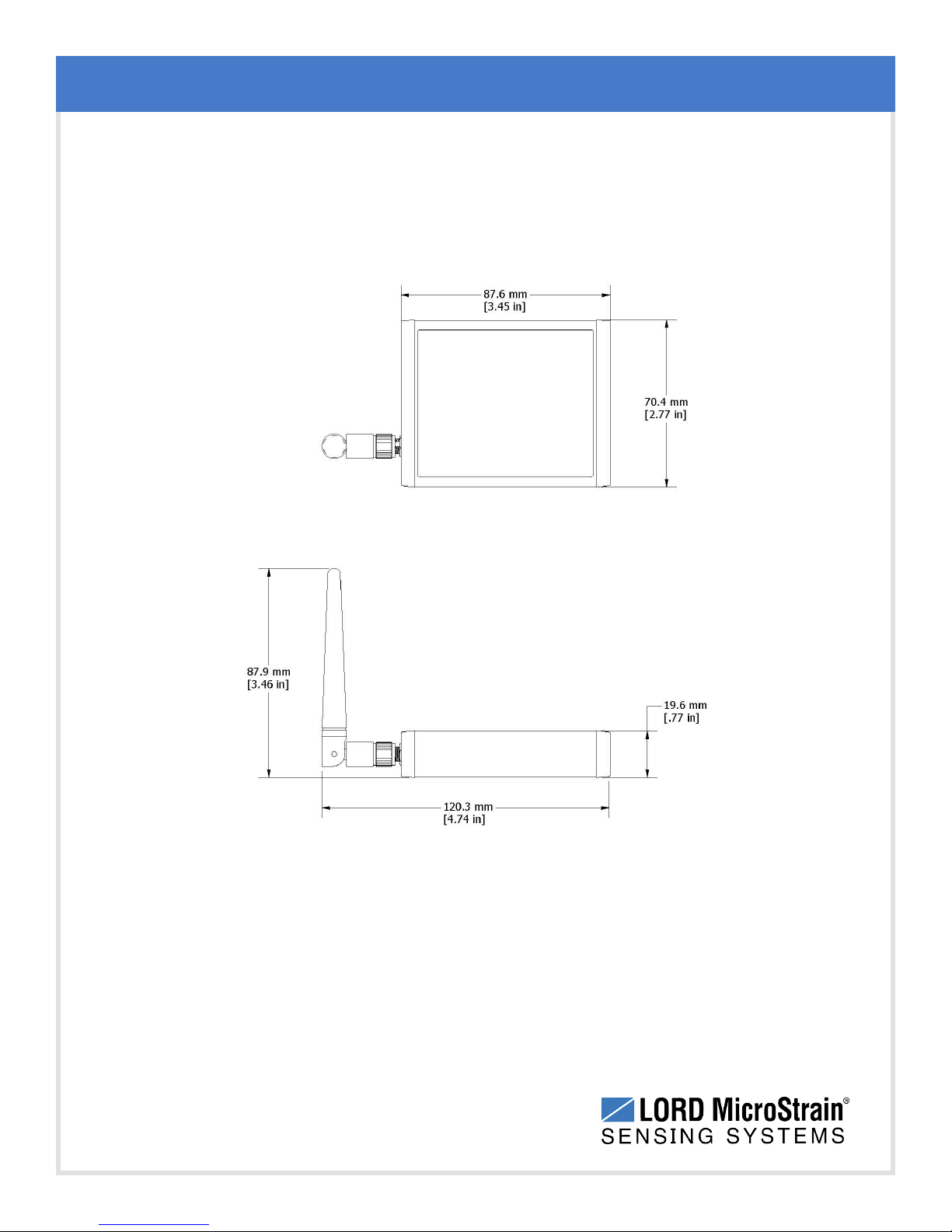
9.1 Physical Specification
Specifications
Enclosure Environmental Rating:
53
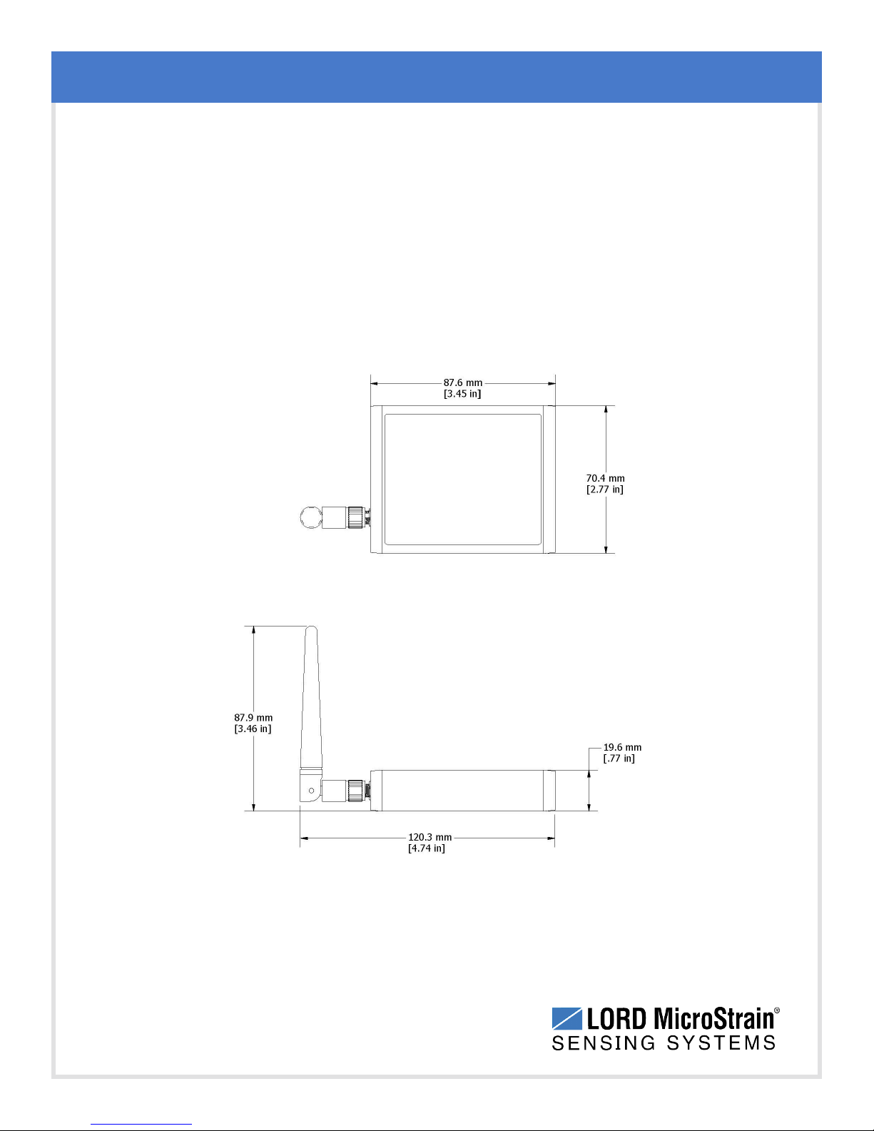
Dimensions:
Weight:
120.3 mm x 70.4 mm x 87.9 mm
123 grams
General purpose indoor
Page 54
WSDA®-Base-104®USBBase Station User Manual
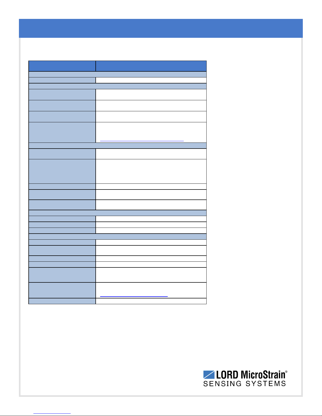
9.2 Operating Specifications
Parameter Specifications
General
Conn ectivity
Supported node sampling
modes
Synchronizatio n beacon
interval
Synchronizatio n beacon
stability
Network capacity
Wireless communi cation r ange
Radio frequency (RF)
transceiver carrier
RF communication protocol
Power consumption
Operating temperature
Dimensions
Weight
Enclosure material
Conn ectors
Communications cable
Compatible sensor nodes
Firmware
Software
Software development kit (SDK)
Regulatory compli ance
USB 2.0 virtual serial c ommunication @ 921,600 bps
Sampling
Synchronized, low duty cycle, continuous, periodic burst,
event-triggered, and datalogging
1 H z beacon provides ± 32 μsec node-to-node sy nchronization
± 3 ppm
Up to 2000 nodes per RF channel (and per gateway) depending
on the number of active channels and sampling settings.
Refer to the system bandwidth calculator:
http:/ /www.microstrain.com/configure-your-system
Operating Parameters
Outdoor/line-of-sight: 2 km(ideal)*, 800 m (typical)**
Indoor/obstructions: 50 m (typical)**
2.405 t o 2.470 GHz direct sequence s pread spectrum over 14
channels, license-free worldwide, radiated power
programmable f rom 0 dBm (1 mW) to 16 dBm (39 mW); (low
power option available for use outside the U.S.A.- limit ed t o 10
dBm (10 mW)
IEEE 802.15.4
Idle: 45.7 mA; Eight active node channels operating at 256 Hz
low duty cycle: 65.6 mA
-40 °C to + 85 °C (electronics)
-30 °C to +70 °C (enclosure/antenna)
Physical Specifications
88 mm x 70 mm x 20 mm without antenna
123 grams
Black anodized aluminum
Integration
Micro-USB
USB s tandard to USB micro-B
(3 f oot cable included in starter kit)
All LXRS®sensor nodes, all legacy 2.4 GHz nodes
Firmware upgradeable through software interface
SensorCloud™,SensorConnect™, Node Commander®,
WSDA®Data Downloader, Live C onnect™, Windows
XP/Vista/7 compatible
Data communications protocol availablewith EEPROM maps
and sample code (OS and computing platform independent)
http:/ /www.microstrain.com/wireless/sdk
FCC (U.S.), IC(Canada), CE, ROHS
Specifications
*Measured with antennas elevated, no o bstructions, and no R F in terferers.
**Actual range varies dependi ng on cond itio ns such as obstru ctions, RF interference, antenna height, & antenna ori entation.
54
Page 55
WSDA®-Base-104®USBBase Station User Manual
9.3 Radio Specifications
The WSDA®-Base-104®USBBase Station employs a 2.4GHz IEEE 802.15.4 compliant radio
transceiver for wireless communication.The radio is a direct-sequence spread spectrum radio
and can be configured to operate on 14 separate frequencies ranging from 2.405 GHz to 2.470
GHz.Following the 802.15.4 standard, these frequencies are aliased as channels 11 through
24.For all newly manufactured nodes, the default setting is 2.425 GHz (channel 15).
For standard models, radiated transmit power is programmable from 0 dBm (1 mW) to 16 dBm
(39 mW). A low-transmit power option is available (for use in Europe and elsewhere) and is
limited to 10 dBm (10 mW).
The radio complies with FCC Part 15 (USA) and IC (Canada) regulations.The radio is licensefree worldwide. Using antennas and transmission equipment other than what is provided may
void FCC compliance.
Specifications
55
Page 56
WSDA®-Base-104®USBBase Station User Manual
10. Safety Information
This section provides a summary of general safety precautions that must be understood and
applied during operation and maintenance of components in the LORD MicroStrain®Wireless
Sensor Network.
10.1 ESD Sensitivity
The WSDA®-Base-104®is susceptible to damage and/or disruption of normal operation from
Electrostatic Discharge (ESD), particularly during data acquisition.
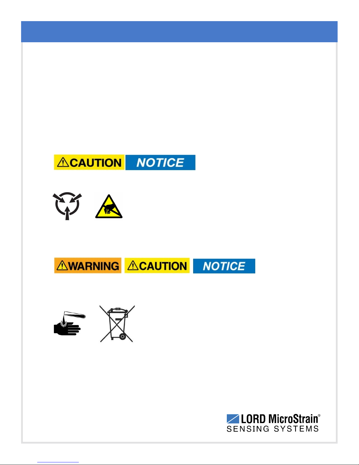
ESD damage can occur when the device is touched,
especially at the device interfaces such as the antenna and
connectors. Use proper grounding techniques when
handling. If an ESD event occurs, and operation has been
interrupted, reset the device by cycling power to it and/or
restarting the operational mode in the system software.
Safety Information
10.2 Disposal and Recycling
The WSDA®- Base- 104®contains internal batteries,
printed circuit boards, and electronic components.These
items are known to contain toxic chemicals and heavy
metals that are harmful to humans health and the
environment. Disposal is subject to federal and local
laws.Do not discard the device or batteries in the trash.
Follow proper electronic and battery waste disposal
protocol, as dictated by federal and local authorities.
Some states also have programs for extracting reusable
parts for recycling.
56
Page 57
WSDA®-Base-104®USBBase Station User Manual
11. References
11.1 Reference Information
Many references are available on the LORD MicroStrain®website including product user
manuals, technical notes, and quick start guides.These documents are continuously updated,
and new applications are added. They may provide more accurate information than printed or
file copies.
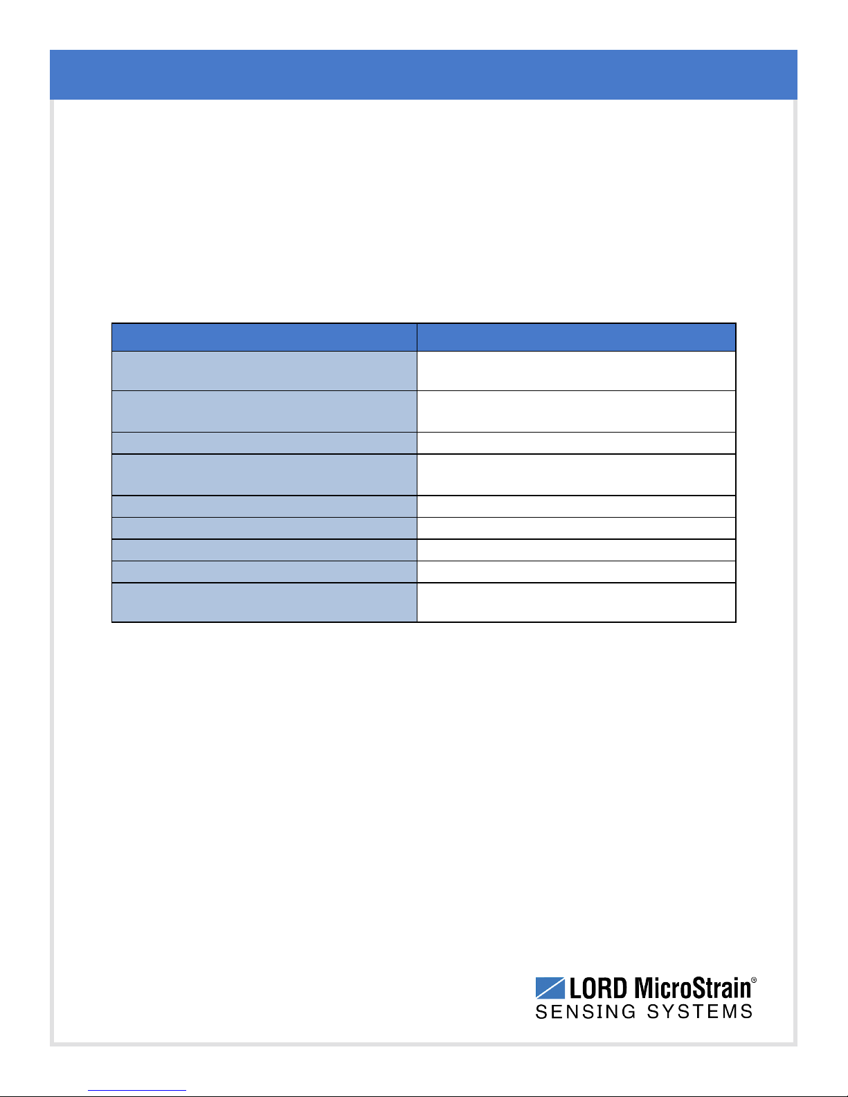
Document Where to find it
References
Online Wireless Network Calculator
SensorCloud™
Overview
MathEngine®Overview
LORD MicroStrain®Wireless Sensors
Network Software Development Kit
Product Datasheets
Product Manuals and Technical Notes
Product Application Notes
NIST Calibration Procedures
ASTM Testing Procedures
Table 6 - Related Documents
http://www.microstrain.com/configure-your-
system
http://www.sensorcloud.com/system-
overview
http://www.sensorcloud.com/mathengine
http://www.microstrain.com/wireless/sdk
http://www.microstrain.com/wireless/sensors
http://www.microstrain.com/support/docs
http://www.microstrain.com/applications
http://www.nist.gov/calibrations/
http://www.astm.org/Standard/standards-
and-publications.html
57
Page 58
WSDA®-Base-104®USBBase Station User Manual
11.2 Glossary
These terms are in common use throughout the manual:
A/D Value: the digital representation of the analog voltages in an analog-to- digital (A/D)
conversion. The accuracy of the conversion is dependent on the resolution of the system
electronics; higher resolution produces a more accurate conversion. Also referred to as "bits".
Base Station: The base station is the transceiver that attaches to the host computer and
provides communication between the software and the node(s). It is also referred to as a
“gateway”.
Burst Sampling: a mode of operation in which the node is sampled for a fixed window of time
(burst), and then repeats that window at set intervals. The burst duration and time between
bursts is configurable. Same as periodic burst sampling.
Calibration: to standardize a measurement by determining the deviation standard and
applying a correction (or calibration) factor
References
Configuration: a general term applied to the node indicating how it is set up for data
acquisition. It includes settings such as sampling mode and rate, number of active channels,
channel measurement settings, offsets, hardware gain, and calibration values.
Continuous Sampling: a mode of operation in which the node is sampled continuously until
stopped, or continuously for a fixed amount of time.
Coordinated Universal Time (UTC): the primary time standard for world clocks and time. It
is similar to Greenwich Mean Time (GMT).
Cycle Power: a command transmitted to the node to reboot it, either through a hardware or
software switch
Data Acquisition: the process of collecting data from sensors and other devices
Data Logging: the process of saving acquired data to the system memory, either locally on
the node or remotely on the host computer
DHCP (network): Dynamic Host Configuration Protocol is the standardized networking
protocol used on Internet Protocol (IP) networks, which automatically configures devices that
are attached to it by assigning and configuring the device IP address.
58
Page 59
WSDA®-Base-104®USBBase Station User Manual
EMI: Electromagnetic Interference is an inductive or radiated disturbance that can create
signal degradation on electrical signals, including loss of data.
ESD: Electrostatic Discharge is the sudden flow of electricity that can occur between two
charged objects of different potential that come in contact or in close proximity of each other.
Static electricity is a common source of ESD.
Event-Based Sampling: a mode of operation in which the node sampling is started when a
sensor measurement value (threshold) is achieved.
Firmware: the code that is programmed onto a microcontroller or similar device in an
embedded system. It includes device operation commands, conditions, memory allocation, and
many other tasks.
Gateway: The gateway is a transceiver that attaches to the host computer and provides
communication between the software and the node(s). It is also known as a “base station”.
Host (computer): The host computer is the computer that orchestrates command and control
of the attached devices or networks.
References
LED: Light Emitting Diode is an indicator light that is used in electronic equipment.
LOS (Line of Sight): is used in radio communications to describe the ideal condition between
transmitting and receiving antennas in a radio network.As stated, it means the antennas are in
view of each other with no obstructions.
LXRS®:Lossless Extended Range Synchronized is the proprietary LORD MicroStrain®data
communications protocol used in the wireless sensor network.
Node: The node is the wireless transceiver that the sensor(s) is connected to, providing
communication with the gateway. The G-Link®-LXRS®, V-Link®-LXRS®, and SG-Link®LXRS®are examples of nodes manufactured by LORD MicroStrain®.
Node Tester board: The Node Tester board is a device designed by LORD MicroStrain®that
can be plugged into nodes to test their functionality.
Offset: When describing a mathematically-linear relationship, the offset is the value where the
line that represents the relationship in a graph crosses the y-axis. The equation of a straight
line is: y = mx+b, where x is the x-axis coordinate, y is the y-axis coordinate, m is the slope and
b is the offset.
59
Page 60

WSDA®-Base-104®USBBase Station User Manual
Oversampling: In signal processing, oversampling is a technique used to achieve increased
signal resolution and better noise immunity by recording readings at a higher frequency than
the output of the device being measured. In analog-to- digital conversion, the higher the
oversampling rate, the better the recreated analog signal.
Packet: unit of sampled data
Periodic Burst Sampling: a mode of operation in which the node is sampled for a fixed
window of time (burst), and then repeats that window at set intervals. The burst duration and
time between bursts is configurable. Same as burst sampling.
Ping: a byte transmitted by the gateway to the node. The node responds by echoing the byte,
indicating communication exists between the node and gateway.
Range Test: a continuous string of pings used to validate communication between the
gateway and the node over distance and obstruction
Real Time Clock (RTC): a computer clock that keeps track of the current time
References
RFI: Radio Frequency Interference is a disturbance in an electrical circuit due to
electromagnetic induction or radiation.
RSSI: Received Signal Strength Indication is a measurement of the transmission power in a
radio signal. It is measured in decibels with reference to 1 milliWatt (dBm).
RS232: a serial data communications protocol
Sensor: a device that physically or chemically reacts to environmental forces and conditions,
producing a predictable electrical signal
Sleep: a command transmitted to the node to put it into sleep configuration
Sampling: the process of taking measurements from a sensor or device
Sampling Mode: the type of sampling that is being utilized, such as event-triggered,
continuous, or periodic.The nodes have several sampling modes that employ these types of
sampling.
Sampling Rate: the frequency of sampling
60
Page 61
WSDA®-Base-104®USBBase Station User Manual
Slope: When describing a mathematically linear relationship, the slope is the steepness of the
line that represents that relationship on a graph. The equation of a straight line is: y = mx+b,
where x is the x-axis coordinate, y is the y-axis coordinate, m is the slope, and b is the offset.
Streaming: Streaming is a sampling mode in which all active channels (and the sensors
attached to them) are measured, and the acquired data is transmitted to the gateway and
software. The data is not written to non- volatile memory during streaming. Streaming can
either be finite (have a user defined start and end time) or continuous (continued until the power
is cycled on the node).
Synchronized Sampling: a sampling mode that automatically coordinates all incoming node
data to a particular gateway. This mode is designed to ensure data arrival and sequence.
Transmission rate: the number of data packets per transmission window, measured in
seconds. Depending on the sampling mode and settings it will be between 1 and 64
packets/second.
Transmission window: the time allowed for one data transmission at the automatically
determined transmission rate
References
USB: Universal Serial Bus, a serial data communications protocol
WSN: Wireless Sensor Network describes a distribution of sensors and data acquisition
equipment that autonomously monitors environmental characteristics, such as temperature,
pressure, and strain.
61
 Loading...